EP1431850A1 - ULTRA−PRECISION MACHINING METHOD AND DEVICE FOR HETEROGENEOUS MATERIAL - Google Patents
ULTRA−PRECISION MACHINING METHOD AND DEVICE FOR HETEROGENEOUS MATERIAL Download PDFInfo
- Publication number
- EP1431850A1 EP1431850A1 EP02760631A EP02760631A EP1431850A1 EP 1431850 A1 EP1431850 A1 EP 1431850A1 EP 02760631 A EP02760631 A EP 02760631A EP 02760631 A EP02760631 A EP 02760631A EP 1431850 A1 EP1431850 A1 EP 1431850A1
- Authority
- EP
- European Patent Office
- Prior art keywords
- processing
- data
- ultra
- simulation
- boundary
- Prior art date
- Legal status (The legal status is an assumption and is not a legal conclusion. Google has not performed a legal analysis and makes no representation as to the accuracy of the status listed.)
- Granted
Links
Images


Classifications
-
- G—PHYSICS
- G05—CONTROLLING; REGULATING
- G05B—CONTROL OR REGULATING SYSTEMS IN GENERAL; FUNCTIONAL ELEMENTS OF SUCH SYSTEMS; MONITORING OR TESTING ARRANGEMENTS FOR SUCH SYSTEMS OR ELEMENTS
- G05B19/00—Program-control systems
- G05B19/02—Program-control systems electric
- G05B19/18—Numerical control [NC], i.e. automatically operating machines, in particular machine tools, e.g. in a manufacturing environment, so as to execute positioning, movement or co-ordinated operations by means of program data in numerical form
- G05B19/4097—Numerical control [NC], i.e. automatically operating machines, in particular machine tools, e.g. in a manufacturing environment, so as to execute positioning, movement or co-ordinated operations by means of program data in numerical form characterised by using design data to control NC machines, e.g. CAD/CAM
-
- G—PHYSICS
- G05—CONTROLLING; REGULATING
- G05B—CONTROL OR REGULATING SYSTEMS IN GENERAL; FUNCTIONAL ELEMENTS OF SUCH SYSTEMS; MONITORING OR TESTING ARRANGEMENTS FOR SUCH SYSTEMS OR ELEMENTS
- G05B19/00—Program-control systems
- G05B19/02—Program-control systems electric
- G05B19/18—Numerical control [NC], i.e. automatically operating machines, in particular machine tools, e.g. in a manufacturing environment, so as to execute positioning, movement or co-ordinated operations by means of program data in numerical form
- G05B19/406—Numerical control [NC], i.e. automatically operating machines, in particular machine tools, e.g. in a manufacturing environment, so as to execute positioning, movement or co-ordinated operations by means of program data in numerical form characterised by monitoring or safety
- G05B19/4069—Simulating machining process on screen
-
- G—PHYSICS
- G05—CONTROLLING; REGULATING
- G05B—CONTROL OR REGULATING SYSTEMS IN GENERAL; FUNCTIONAL ELEMENTS OF SUCH SYSTEMS; MONITORING OR TESTING ARRANGEMENTS FOR SUCH SYSTEMS OR ELEMENTS
- G05B2219/00—Program-control systems
- G05B2219/30—Nc systems
- G05B2219/36—Nc in input of data, input key till input tape
- G05B2219/36063—During machining, compare simulated with detected profile, correct, modify program
-
- Y—GENERAL TAGGING OF NEW TECHNOLOGICAL DEVELOPMENTS; GENERAL TAGGING OF CROSS-SECTIONAL TECHNOLOGIES SPANNING OVER SEVERAL SECTIONS OF THE IPC; TECHNICAL SUBJECTS COVERED BY FORMER USPC CROSS-REFERENCE ART COLLECTIONS [XRACs] AND DIGESTS
- Y02—TECHNOLOGIES OR APPLICATIONS FOR MITIGATION OR ADAPTATION AGAINST CLIMATE CHANGE
- Y02P—CLIMATE CHANGE MITIGATION TECHNOLOGIES IN THE PRODUCTION OR PROCESSING OF GOODS
- Y02P90/00—Enabling technologies with a potential contribution to greenhouse gas [GHG] emissions mitigation
- Y02P90/02—Total factory control, e.g. smart factories, flexible manufacturing systems [FMS] or integrated manufacturing systems [IMS]
-
- Y—GENERAL TAGGING OF NEW TECHNOLOGICAL DEVELOPMENTS; GENERAL TAGGING OF CROSS-SECTIONAL TECHNOLOGIES SPANNING OVER SEVERAL SECTIONS OF THE IPC; TECHNICAL SUBJECTS COVERED BY FORMER USPC CROSS-REFERENCE ART COLLECTIONS [XRACs] AND DIGESTS
- Y10—TECHNICAL SUBJECTS COVERED BY FORMER USPC
- Y10T—TECHNICAL SUBJECTS COVERED BY FORMER US CLASSIFICATION
- Y10T409/00—Gear cutting, milling, or planing
- Y10T409/30—Milling
- Y10T409/30084—Milling with regulation of operation by templet, card, or other replaceable information supply
- Y10T409/300896—Milling with regulation of operation by templet, card, or other replaceable information supply with sensing of numerical information and regulation without mechanical connection between sensing means and regulated means [i.e., numerical control]
Definitions
- the present invention relates to an ultra-precise processing method and apparatus for an inhomogeneous material, which can perform ultra-precise processing even when a workpiece or a tool has low rigidity and an inconstant deformation quantity.
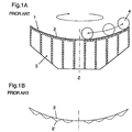
- FIG. 1A is a type drawing showing a processing step of a large-diameter lightweight mirror for a large reflecting telescope used in the outer space.
- This large-diameter lightweight mirror 1 includes a thin reflecting plate 2 (for example, a thickness of 3 to 5 mm) supported by a honey-comb body 3 in order to reduce the weight.
- this large-diameter lightweight mirror has a large diameter of, e.g., 300 to 700 mm, its weight is restricted to less than 150 kg.
- a processing tool 4 for example, a cylindrical grinding stone
- a predetermined curve for example, a parabola
- the reflecting plate 2 is just partially supported by the honey-comb body 3, and the rigidity of the reflecting plate 2 at a part not supported by the honey-comb body 3 is low. Therefore, during the grinding process using the processing tool, a contact arc length between the processing tool and the reflecting plate 2 (workpiece) largely varies depending on a processing position, and the processing resistance also greatly fluctuates. Therefore, the deformation of the workpiece itself partially differs, and deformation as indicated by a thin line 2' in FIG. 1B is generated, for example.
- the present invention has been contrived in order to solve the above-described problems. That is, it is an object of the present invention to provide an ultra-precise processing method and apparatus for an inhomogeneous material, which enable ultra-precise processing even when a workpiece or a tool has low rigidity and an inconstant quantity of deformation.
- This method of storing entity data divides external data consisting of boundary data of an object into rectangular parallelepiped internal cells and boundary cells having boundary planes orthogonal to each other in accordance with octree (oct-tree) division, and stores various physical properties in accordance with the respective cells.
- octree oct-tree
- a shape, a structure, physical information and history of an object can be managed in an integrated fashion, data concerning a series of processes such as design, processing, assembling, test, evaluation and others can be managed with the same data, and CAD and simulation can be integrated.
- V-CAD data the entity data combining the shape and the physical property
- an ultra-precise processing method for an inhomogeneous material comprising the steps of: (A) preparing V-CAD data obtained by dividing external data consisting of boundary data of an object (1) into rectangular parallelepiped cells (13) having boundary planes orthogonal to each other in accordance with octree division, and separating the respective divided cells into internal cells (13a) positioned on the inner side of the object and boundary cells (13b) including a boundary face; and (B) generating an NC program by using the V-CAD data and subjecting the object to NC processing by the NC program.
- a processed surface shape of the object after NC processing is predicted by simulation using the V-CAD data
- D the processed surface shape of the object after NC processing is measured
- E processing correction data is obtained from a difference between processed surface shapes acquired by the simulation and the measurement, and the NC program is corrected based on the processing correction data.
- the V-CAD data is stored, which is obtained by dividing the external data of the object (1) into rectangular parallelepiped cells (13) having boundary planes orthogonal to each other in accordance with octree division, and separating the respective divided cells into the internal cells (13a) positioned on the inner side of the object and the boundary cells (13b) including the boundary face, the external data can be stored by using a small storage capacity as a hierarchy of the cells.
- the processed surface shape after NC processing is predicted by simulation by using the V-CAD data, accurate simulation can be performed taking physical properties of respective portions into consideration even if the object is an inhomogeneous material and has low rigidity and an inconstant quantity of deformation.
- the object is actually subjected to NC processing by a predetermined NC program, the processed surface shape after this processing is measured, the processing correction data is obtained from a difference between the processed surface shapes acquired by the simulation and the measurement, and the NC program is corrected based on the processing correction data. Therefore, the processing characteristics which cannot be predicted by the simulation can be also taken into consideration for the next NC program.
- a stress when attaching the object, a load and a quantity of deformation due to heat generation/vibrations during processing, roughness, a transmittance, and quantities of deformation of a processing tool and a processing system are simulated, and prediction data of a quantity of deformation, roughness and a transmittance of each portion of the object is thereby generated.
- the simulation is carried out by using a finite element method by mesh generation based on the V-CAD data of the object.
- the simulation is carried out by using the finite element method through modeling and mesh generation of the processing tool and the processing system.
- measurement data of a shape, a dimension error, roughness and a transmittance at each part of the object after NC processing is generated.
- the accuracy of the measurement can be increased by using these measurement means.
- the NC processing includes cutting processing, grinding processing or a composite process thereof. Further, the grinding processing uses electrolytic dressing utilizing a metal bonded grinding stone.
- the high-precision and high-quality ultra-precise processing is enabled by using the above-described processing means.
- FIG. 2 is an entire structural view of an ultra-precise processing apparatus according to the present invention.
- the ultra-precise processing apparatus according to the present invention includes a storage device 24 which stores V-CAD data 14, a simulation program 20 and data correction program 22, an NC processing device 26, and a measurement device 28.
- a workpiece (object 1) may be a large-diameter lightweight mirror shown in FIGS. 1A and 1B or any other inhomogeneous material having low rigidity and an inconstant quantity of deformation. Furthermore, the present invention is not restricted to such a material, and it can be likewise applied to a homogeneous material having high rigidity.
- the NC processing device 26 includes a rotary table 26a which rotates and drives a processed object, i.e., a workpiece (object 1) around its vertical center axis Z.
- the NC processing device 26 includes a processing tool 26b used to process the workpiece 1.
- the cylindrical processing tool 26b is moved along a predetermined curve (for example, a parabola) by the NC control while rotating the workpiece 1 around its center axis Z to process the surface of the workpiece 1 by the processing tool 26b.
- the processing tool 26b has, e.g., a cylindrical shape, a spherical shape or a planar shape.
- the NC processing is not restricted to grinding processing using a grinding stone, and it may be cutting processing, polishing processing or a composite process combining such processing.
- the high-precision and high-quality ultra-precise processing can be highly efficiently performed by using the electrolytic dressing utilizing a metal bonded grinding stone.
- the measurement device 28 is, e.g., a laser type non-contact probe and measures the processed surface shape of the workpiece 1 on the NC processing device 26 after NC processing. It is to be noted that the present invention is not restricted to the laser type, and a contact type probe with a low contact pressure or a non-contact type probe using the atomic force may be used or measurement of a transmittance may be optically performed. Moreover, in addition to the measurement of the processed surface shape, it is desirable to also measure a shape dimension error or shape roughness in each portion of the object after NC processing, a transmittance of an optical element and others.
- the V-CAD data 14 is obtained by dividing external data consisting of boundary data of the object 1 into rectangular parallelepiped cells 13 having boundary plans orthogonal to each other in accordance with octree division, and separating the respective divided cells into internal cells 13a positioned on the inner side of the object and boundary cells 13b including a boundary face.
- simulation program 20 is designed to predict a processed surface shape after NC processing by simulation using the V-CAD data 14.
- the data correction program 22 is designed to obtain processing correction data from a difference between the processed surface shapes acquired (predicted) by simulation and the processed surface shape acquired by the measurement, and correct the NC program based on the processing correction data.
- FIG. 3 is an explanatory view of a data structure in an ultra-precise processing according to the present invention.
- the modified octree space division is performed.
- the octree expression namely, the space division based on octree divides a standard rectangular solid 13 which includes a target solid (object) into eight parts as shown in (A) of the drawing, and recursively repeats the eight-part division processing until the solid is completely included in or excluded from each area as shown in (B), (C) and (D) of the drawing.
- the cell is a rectangular parallelepiped having boundary planes orthogonal to each other.
- the areas occupying in the space are represented by a hierarchical structure based on the cells, the division number or a resolution. As a result, the object in the entire space is represented as superimposition of the cells having the different sizes.
- the boundary and the inside physical property are converted into the following entity data 14 (V-CAD data) from the external data.
- the boundary data approximates exactly (for example, in case of a flat plane, it can be exactly reconfigured at three points included therein) or in a specified limit deviation tolerance (a position, a tangent line, a normal line and a curvature, and threshold values specified for the connectivity of them with the neighboring areas).
- a special case of an interpolation curve is a Marching Cube.
- subdivision is necessarily performed until expression at cut points on an edge line becomes possible and until the normal line or a main curvature and the continuity are satisfied.
- the surface of the second (quadratic) or lower order is exactly expressed, and a free-form surface is approximated by the surface in the cell based on the flat surface or the surface of the second order, thereby saving only a geometric inherent quantity.
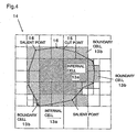
- FIG. 4 is a type drawing two-dimensionally showing the division method according to the present invention.
- the respective divided cells 13 are separated into internal cells 13a positioned on the inner side of the object and boundary cells 13b including a boundary face.
- the modified octree is used in order to express the boundary cell 13b, cells which are completely included inside are constituted by the internal cells 13a (rectangular parallelepiped) having the maximum size, and cells including boundary information from the external data are constituted as the boundary cells 13b.
- Each boundary cell 13b is exactly or approximately replaced with cut points 15 (indicated by the white circle in the drawing) on 12 edge lines in the three-dimensional expression or four edge lines in the two-dimensional expression.
- the boundary cell 13b is subjected to octree division until the sufficient cut points 15 can be obtained, with which boundary shape elements constituting the boundaries included in the external data can be reconfigured (exactly with respect to analytic surfaces such as a flat surface or a quadric surface, and approximately with respect to boundary shape elements which can be expressed by a free-form surface or a discrete point group).
- the space is hierarchically divided into eight parts until two points on one line segment become cut points 15 on the edge line of the cell in case of one line segment, until three points become the cut points in case of a flat surface, until three points become cut points in case of a quadratic curve, until four points become cut points in case of a quadratic surface, and until necessary and sufficient points and edge lines of the cell can be found in a defined range in cases where the expression of the external data is known with respect to each of a polynomial surface and a rational expression surface.
- division is carried out until a position to be subjected to subdivision satisfies a specified resolution at a boundary (surface) part or until a rate of change of a value of an analysis result (a stress, a distortion, a pressure, a flow velocity or the like) becomes equal to or lower than a specified threshold value.
- the boundary therein can be indirectly expressed as an intersecting line of the boundary expressed by the cut point 15 held by an adjacent boundary cell (which has the cut points sufficient for reconfiguration and is divided until the boundary elements completely come across), and hence subdivision is not carried out more than needs.
- the V-CAD data 14 becomes, as information concerning the shapes stored inside the cell, an index indicating a position of the cell, the division number or a resolution indicating a degree of detail in the hierarchy, a pointer indicating an adjacent cell, the number of cut points, and coordinate values of cut points. Further, depending on use application, the V-CAD data 14 can become a normal line, a curvature, or the like.
- node information or values of the result are held in the form of Euler in the lowermost layer.
- a threshold value limit deviation tolerance
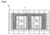
- FIG. 5 is a type drawing showing the workpiece 1 (object) in the form of the V-CAD data.
- the V-CAD data of the workpiece 1 is first prepared. That is, as shown in FIG. 5, the workpiece 1 is separated into the internal cells 13a and the boundary cells 13b in the V-CAD data.
- this V-CAD data 14 design data, measurement data acquired by a digitizer or voxel data is converted and used, and new V-CAD data is reconfigured every time simulation or measurement is carried out.
- the V-CAD data 14 is then used and a processed surface shape after NC processing is predicted by simulation.
- the object 1 is subjected to NC processing by a predetermined NC program, and a processed surface shape after NC processing is measured.
- processing correction data is obtained from a difference between the processed surface shape acquired by the simulation and the processed surface shape acquired by the measurement, and the NC program is corrected based on the processing correction data.
- simulation it is desirable to simulate a stress when attaching the object, a load and a quantity of deformation due to heat generation/vibrations during processing, roughness, a transmittance and a quantity of deformation of a processing tool and a processing system, and thereby generate prediction data or the like of a quantity of deformation, roughness and a transmittance in each portion of the object.
- simulation is carried out by mesh generation based on the V-CAD data of the object, by a finite element method, and modeling and mesh generation of the processing tool and the processing system in simulation are also performed by using the finite element method.
- the V-CAD data 14 is stored, which is obtained by dividing the external data of the object 1 into rectangular parallelepiped cells 13 having boundary planes orthogonal to each other in accordance with the octree division, and separating the respective divided cells into the internal cells 13a positioned on the inner side of the object and the boundary cells 13b including the boundary face, the external data can be stored with a small storage capacity as a hierarchy of the cells.
- the processed surface shape after NC processing is predicted by simulation, the accurate simulation can be performed by taking a physical property of each portion into consideration even if the object is an inhomogeneous material and has the low rigidity and an inconstant quantity of deformation.
- the object is actually subjected to NC processing by using a predetermined NC program, a processed surface shape of the object on the NC processing device after processing is measured, processing correction data is obtained from a difference between the processed surface shape acquired by the simulation and the processed surface shape acquired by the measurement, and the NC program is corrected based on the processing correction data. Therefore, errors of simulation itself or the processing characteristics which cannot be predicted by simulation can be modified and taken into consideration for the next NC program.
- the ultra-precise processing method and apparatus for an inhomogeneous material according to the present invention have the excellent advantages, for example, enabling the ultra-precise processing even if the workpiece or the tool has the low rigidity and an inconstant quantity of deformation.
Landscapes
- Engineering & Computer Science (AREA)
- Human Computer Interaction (AREA)
- Manufacturing & Machinery (AREA)
- Physics & Mathematics (AREA)
- General Physics & Mathematics (AREA)
- Automation & Control Theory (AREA)
- Numerical Control (AREA)
Abstract
Description
Claims (10)
- An ultra-precise processing method for an inhomogeneous material, comprising the steps of:(A) preparing V-CAD data obtained by dividing external data consisting of boundary data of an object (1) into rectangular parallelepiped cells (13) having boundary planes orthogonal to each other in accordance with octree division, and separating the respective divided cells into internal cells (13a) positioned on the inner side of the object and boundary cells (13b) including a boundary face; and(B) generating an NC program by using the V-CAD data and subjecting the object to NC processing by using the NC program.
- The ultra-precise processing method for an inhomogeneous material according to claim 1, further comprising:(C) predicting a processed surface shape of the object after NC processing by simulation using the V-CAD data;(D) measuring a processed surface shape of the object after NC processing; and(E) obtaining processing correction data from a difference between the processed surface shapes acquired by the simulation and the measurement, and correcting the NC program based on the processing correction data.
- The ultra-precise processing method for an inhomogeneous material according to claim 2, wherein a stress at the time of attaching the object, a load and a quantity of deformation due to heat generation/vibrations during processing, roughness, a transmittance, and quantities of deformation of a processing tool and a processing system are simulated in the simulation, and prediction data of a quantity of deformation, roughness and a transmittance in each portion of the object is thereby generated.
- The ultra-precise processing method for an inhomogeneous material according to claim 2, wherein the simulation is carried out by mesh generation based on the V-CAD data of the object by using a finite element method.
- The ultra-precise processing method for an inhomogeneous material according to claim 2, wherein the simulation is carried out by a finite element method through modeling and mesh generation of the processing tool and the processing system.
- The ultra-precise processing method for an inhomogeneous material according to claim 2, wherein measurement data of a shape, a dimension error, roughness and a transmittance in each portion of the object after NC processing is generated in the measurement.
- The ultra-precise processing method for an inhomogeneous material according to claim 2, wherein the measurement performs surface measurement using a contact type probe having a low contact pressure, a laser or a non-contact type probe using the atomic force, and optical measurement of a transmittance.
- The ultra-precise processing method for an inhomogeneous material according to claim 1, wherein the NC processing includes cutting processing, grinding processing, or a composite process thereof.
- The ultra-precise processing method for an inhomogeneous material according to claim 8, wherein the grinding processing uses electrolytic dressing using a metal bonded grinding stone.
- An ultra-precise processing apparatus for an inhomogeneous material, comprising:wherein processing correction data is obtained from a difference between the processed surface shapes acquired by simulation and measurement, and the NC program is corrected based on the processing correction data.a storage device (24) which stores V-CAD data (14) obtained by dividing external data consisting of boundary data of an object (1) into rectangular parallelepiped cells (13) having boundary planes orthogonal to each other in accordance with octree division and separating the respective divided cells into internal cells (13a) positioned on the inner side of the object and boundary cells (13b) including a boundary face, the storage device further storing a simulation program (20) used to predict a processed surface shape after NC processing by simulation using the V-CAD data, and a data correction program (22) used to correct the NC program;an NC processing device (26) which subjects the object to NC processing by a predetermined NC program; anda measurement device (28) which measures a processed surface shape of the object on the NC processing device after NC processing,
Applications Claiming Priority (3)
| Application Number | Priority Date | Filing Date | Title |
|---|---|---|---|
| JP2001246951 | 2001-08-16 | ||
| JP2001246951 | 2001-08-16 | ||
| PCT/JP2002/008269 WO2003017017A1 (en) | 2001-08-16 | 2002-08-14 | Ultra-precision machining method and device for heterogeneous material |
Publications (3)
| Publication Number | Publication Date |
|---|---|
| EP1431850A1 true EP1431850A1 (en) | 2004-06-23 |
| EP1431850A4 EP1431850A4 (en) | 2007-10-31 |
| EP1431850B1 EP1431850B1 (en) | 2010-07-14 |
Family
ID=19076388
Family Applications (1)
| Application Number | Title | Priority Date | Filing Date |
|---|---|---|---|
| EP02760631A Expired - Lifetime EP1431850B1 (en) | 2001-08-16 | 2002-08-14 | Ultra-precision machining method and device for heterogeneous material |
Country Status (5)
| Country | Link |
|---|---|
| US (1) | US7174236B2 (en) |
| EP (1) | EP1431850B1 (en) |
| JP (1) | JP4325931B2 (en) |
| DE (1) | DE60237020D1 (en) |
| WO (1) | WO2003017017A1 (en) |
Cited By (1)
| Publication number | Priority date | Publication date | Assignee | Title |
|---|---|---|---|---|
| EP2148258A4 (en) * | 2007-05-17 | 2010-07-28 | Masaki Sato | Simulation or modeling method of cutting, program of that method, and medium recording that program |
Families Citing this family (13)
| Publication number | Priority date | Publication date | Assignee | Title |
|---|---|---|---|---|
| DE10341778A1 (en) * | 2003-09-10 | 2005-05-25 | P & L Gmbh & Co. Kg | Workpiece machining method in which online error correction is carried out in a second machining stage by calculation of normal surface vectors at tool contact points and the tool is moved a correction amount along the vector |
| JP4582067B2 (en) * | 2006-08-02 | 2010-11-17 | トヨタ自動車株式会社 | Shape prediction apparatus, shape prediction method, and computer program therefor |
| WO2008023433A1 (en) * | 2006-08-25 | 2008-02-28 | Pioneer Corporation | Lens drive device and method of producing lens drive device |
| JP2008076100A (en) * | 2006-09-19 | 2008-04-03 | Ricoh Co Ltd | Method for measuring surface charge distribution or surface potential distribution, measuring apparatus, and image forming apparatus |
| US7948489B1 (en) * | 2007-05-30 | 2011-05-24 | Adobe Systems Incorporated | Minimizing tessellation of surfaces |
| US8217936B1 (en) | 2007-05-30 | 2012-07-10 | Adobe Systems Incorporated | Minimizing tessellation of surfaces |
| JP5176456B2 (en) * | 2007-09-28 | 2013-04-03 | 富士通株式会社 | Ultrasonic horn design support device, ultrasonic horn design support method and program for the device |
| JP5278758B2 (en) * | 2009-05-15 | 2013-09-04 | 本田技研工業株式会社 | Cam drive device and processing method |
| GB201223303D0 (en) * | 2012-12-21 | 2013-02-06 | Hexcel Composites Sarl | Method of producing a shaped component |
| CN112218738B (en) | 2018-06-01 | 2023-06-23 | 巴斯夫欧洲公司 | Method for determining the geometry of blank parts formed in a hydroerosive grinding process to form finished parts |
| JP7362468B2 (en) * | 2019-12-20 | 2023-10-17 | 日立Geニュークリア・エナジー株式会社 | Machined surface shape prediction device and method |
| WO2023017560A1 (en) * | 2021-08-10 | 2023-02-16 | ファナック株式会社 | Evaluation system and evaluation program for evaluating machined surface quality |
| WO2026078297A1 (en) * | 2024-10-08 | 2026-04-16 | Finn-Power Oy | Method for producing processing instructions for machine tool system in relation to workpiece, computer program product, computer system, and machine tool system |
Family Cites Families (20)
| Publication number | Priority date | Publication date | Assignee | Title |
|---|---|---|---|---|
| US4694404A (en) | 1984-01-12 | 1987-09-15 | Key Bank N.A. | High-speed image generation of complex solid objects using octree encoding |
| US5197013A (en) | 1987-07-28 | 1993-03-23 | David M. Dundorf | Method of forming a carved sign using an axially rotating carving tool |
| JP2920195B2 (en) | 1989-03-10 | 1999-07-19 | 株式会社日立製作所 | Shape conversion method and device |
| US5014207A (en) | 1989-04-21 | 1991-05-07 | E. I. Du Pont De Nemours And Company | Solid imaging system |
| JPH0741514B2 (en) | 1990-07-17 | 1995-05-10 | 日立精機株式会社 | Tool selection method for interactive numerical control system |
| US5517602A (en) | 1992-12-03 | 1996-05-14 | Hewlett-Packard Company | Method and apparatus for generating a topologically consistent visual representation of a three dimensional surface |
| JPH06315849A (en) * | 1993-03-04 | 1994-11-15 | Nikon Corp | Formation of polishing program and forming device therewith |
| JPH07334541A (en) | 1994-06-08 | 1995-12-22 | Hitachi Ltd | Numerical analysis element creation system |
| US6075538A (en) | 1996-07-25 | 2000-06-13 | Institute Of High Performance Computing | Time and space efficient data structure and method and apparatus for using the same for surface rendering |
| JPH1063873A (en) | 1996-08-23 | 1998-03-06 | Atr Tsushin Syst Kenkyusho:Kk | Octal tree generating method |
| JP3344558B2 (en) * | 1998-02-26 | 2002-11-11 | 理化学研究所 | Electric dressing grinding method and apparatus |
| JP3388203B2 (en) | 1999-05-28 | 2003-03-17 | 株式会社半導体先端テクノロジーズ | Shape simulation method, apparatus and recording medium |
| US6214279B1 (en) | 1999-10-02 | 2001-04-10 | Nanotek Instruments, Inc. | Apparatus and process for freeform fabrication of composite reinforcement preforms |
| US6627835B1 (en) | 2000-02-02 | 2003-09-30 | Purdue Research Foundation | Three dimensional object fabrication techniques |
| US6606528B1 (en) | 2000-06-21 | 2003-08-12 | The Boeing Company | Method for creating computer-aided design (CAD) solid models from numerically controlled (NC) machine instructions |
| US6471800B2 (en) | 2000-11-29 | 2002-10-29 | Nanotek Instruments, Inc. | Layer-additive method and apparatus for freeform fabrication of 3-D objects |
| JP3468464B2 (en) | 2001-02-01 | 2003-11-17 | 理化学研究所 | Volume data generation method integrating shape and physical properties |
| JP2004521423A (en) | 2001-03-12 | 2004-07-15 | コーニンクレッカ フィリップス エレクトロニクス エヌ ヴィ | Generation of 3D representation from many images using octree |
| DE60224285T2 (en) * | 2001-08-16 | 2009-01-02 | Riken, Wako | CHIP PROCESSING AND INSTALLATION BY V-CAD DATA |
| US7406361B2 (en) * | 2001-08-16 | 2008-07-29 | Riken | Rapid prototyping method and apparatus using V-CAD data |
-
2002
- 2002-08-14 US US10/486,654 patent/US7174236B2/en not_active Expired - Fee Related
- 2002-08-14 WO PCT/JP2002/008269 patent/WO2003017017A1/en not_active Ceased
- 2002-08-14 EP EP02760631A patent/EP1431850B1/en not_active Expired - Lifetime
- 2002-08-14 DE DE60237020T patent/DE60237020D1/en not_active Expired - Lifetime
- 2002-08-14 JP JP2003521460A patent/JP4325931B2/en not_active Expired - Fee Related
Cited By (1)
| Publication number | Priority date | Publication date | Assignee | Title |
|---|---|---|---|---|
| EP2148258A4 (en) * | 2007-05-17 | 2010-07-28 | Masaki Sato | Simulation or modeling method of cutting, program of that method, and medium recording that program |
Also Published As
| Publication number | Publication date |
|---|---|
| US20050033471A1 (en) | 2005-02-10 |
| WO2003017017A1 (en) | 2003-02-27 |
| JPWO2003017017A1 (en) | 2004-12-09 |
| JP4325931B2 (en) | 2009-09-02 |
| EP1431850B1 (en) | 2010-07-14 |
| DE60237020D1 (en) | 2010-08-26 |
| EP1431850A4 (en) | 2007-10-31 |
| US7174236B2 (en) | 2007-02-06 |
Similar Documents
| Publication | Publication Date | Title |
|---|---|---|
| US7174236B2 (en) | Ultra-precise processing method and apparatus for inhomogeneous material | |
| Das et al. | Optimum part build orientation in additive manufacturing for minimizing part errors and support structures | |
| EP1229463A2 (en) | Storage method of substantial data integrating shape and physical properties | |
| US7840367B2 (en) | Multi-modality inspection system | |
| Heinze et al. | A parametric model for probabilistic analysis of turbine blades considering real geometric effects | |
| US12115584B2 (en) | 3D printing of high stiffness-to-weight reflective optics | |
| Lazarević et al. | Optical inspection of cutting parts by 3D scanning | |
| Wang et al. | A novel 3D surface topography prediction algorithm for complex ruled surface milling and partition process optimization | |
| Liu et al. | High precision measurement of blade profile curve using iterative normal vector approximation | |
| CN114782315B (en) | Method, device, equipment and storage medium for detecting shaft-hole assembly posture accuracy | |
| Mahboubkhah et al. | An investigation on measurement accuracy of digitizing methods in turbine blade reverse engineering | |
| Li et al. | Section curve reconstruction and mean-camber curve extraction of a point-sampled blade surface | |
| CN121143199A (en) | A method and related equipment for compensating machining errors of CNC machine tool parts | |
| Lai et al. | Machining error inspection of T-spline surface by on-machine measurement | |
| CN119984095A (en) | A measuring device for processing hyperbolic aluminum plates | |
| US7110852B2 (en) | Die machining method and device by V-CAD data | |
| Chen et al. | Design for manufacturing: Geometric manufacturability evaluation for five-axis milling | |
| Tao et al. | An optimized single-point offset method for reducing the theoretical error of S-shaped test piece | |
| Kelkar et al. | Geometric algorithms for rapidly reconfigurable mold manufacturing of free-form objects | |
| CN109035238A (en) | A kind of machining allowance off-line analysis method towards Free-form Surface Parts | |
| Van Gestel | Determining measurement uncertainties of feature measurements on CMMs | |
| US20190204571A1 (en) | Method and Device for Producing an Optical Component Having at Least Three Monolithically Arranged Optical Functional Surfaces and Optical Component | |
| CN121540087B (en) | A method and system for calibrating the degrees of freedom of a multi-set line structured optical probe. | |
| D Souza | Design for inspection: Optimizing medical device designs for manufacturing and inspection through case studies using geometric dimensioning and tolerancing (GD&T) in accordance with ASME Y14. 5 2018 standards | |
| Yunyong et al. | Geometric analysis of investment casting turbine blades based on digital measurement data. |
Legal Events
| Date | Code | Title | Description |
|---|---|---|---|
| PUAI | Public reference made under article 153(3) epc to a published international application that has entered the european phase |
Free format text: ORIGINAL CODE: 0009012 |
|
| 17P | Request for examination filed |
Effective date: 20040216 |
|
| AK | Designated contracting states |
Kind code of ref document: A1 Designated state(s): AT BE BG CH CY CZ DE DK EE ES FI FR GB GR IE IT LI LU MC NL PT SE SK TR |
|
| A4 | Supplementary search report drawn up and despatched |
Effective date: 20070927 |
|
| 17Q | First examination report despatched |
Effective date: 20071214 |
|
| RTI1 | Title (correction) |
Free format text: ULTRA-PRECISION MACHINING METHOD AND DEVICE FOR HETEROGENEOUS MATERIAL |
|
| GRAP | Despatch of communication of intention to grant a patent |
Free format text: ORIGINAL CODE: EPIDOSNIGR1 |
|
| RBV | Designated contracting states (corrected) |
Designated state(s): DE GB |
|
| GRAS | Grant fee paid |
Free format text: ORIGINAL CODE: EPIDOSNIGR3 |
|
| GRAA | (expected) grant |
Free format text: ORIGINAL CODE: 0009210 |
|
| AK | Designated contracting states |
Kind code of ref document: B1 Designated state(s): DE GB |
|
| REG | Reference to a national code |
Ref country code: GB Ref legal event code: FG4D |
|
| REF | Corresponds to: |
Ref document number: 60237020 Country of ref document: DE Date of ref document: 20100826 Kind code of ref document: P |
|
| PGFP | Annual fee paid to national office [announced via postgrant information from national office to epo] |
Ref country code: DE Payment date: 20100929 Year of fee payment: 9 |
|
| PLBE | No opposition filed within time limit |
Free format text: ORIGINAL CODE: 0009261 |
|
| STAA | Information on the status of an ep patent application or granted ep patent |
Free format text: STATUS: NO OPPOSITION FILED WITHIN TIME LIMIT |
|
| 26N | No opposition filed |
Effective date: 20110415 |
|
| REG | Reference to a national code |
Ref country code: DE Ref legal event code: R097 Ref document number: 60237020 Country of ref document: DE Effective date: 20110415 |
|
| PGFP | Annual fee paid to national office [announced via postgrant information from national office to epo] |
Ref country code: GB Payment date: 20110830 Year of fee payment: 10 |
|
| GBPC | Gb: european patent ceased through non-payment of renewal fee |
Effective date: 20120814 |
|
| PG25 | Lapsed in a contracting state [announced via postgrant information from national office to epo] |
Ref country code: GB Free format text: LAPSE BECAUSE OF NON-PAYMENT OF DUE FEES Effective date: 20120814 Ref country code: DE Free format text: LAPSE BECAUSE OF NON-PAYMENT OF DUE FEES Effective date: 20130301 |
|
| REG | Reference to a national code |
Ref country code: DE Ref legal event code: R119 Ref document number: 60237020 Country of ref document: DE Effective date: 20130301 |