EP1431783B1 - Light transmitting material, structure connecting light transmitting material and optical device, and method for manufacturing light transmitting material - Google Patents
Light transmitting material, structure connecting light transmitting material and optical device, and method for manufacturing light transmitting material Download PDFInfo
- Publication number
- EP1431783B1 EP1431783B1 EP20020762857 EP02762857A EP1431783B1 EP 1431783 B1 EP1431783 B1 EP 1431783B1 EP 20020762857 EP20020762857 EP 20020762857 EP 02762857 A EP02762857 A EP 02762857A EP 1431783 B1 EP1431783 B1 EP 1431783B1
- Authority
- EP
- European Patent Office
- Prior art keywords
- light transmitting
- transmitting material
- light
- core material
- reactivity
- Prior art date
- Legal status (The legal status is an assumption and is not a legal conclusion. Google has not performed a legal analysis and makes no representation as to the accuracy of the status listed.)
- Expired - Lifetime
Links
- 239000000463 material Substances 0.000 title claims abstract description 406
- 230000003287 optical effect Effects 0.000 title claims description 87
- 238000000034 method Methods 0.000 title claims description 30
- 238000004519 manufacturing process Methods 0.000 title claims description 28
- 239000011162 core material Substances 0.000 claims abstract description 142
- 150000001875 compounds Chemical class 0.000 claims abstract description 73
- 125000002887 hydroxy group Chemical group [H]O* 0.000 claims abstract description 66
- 230000009257 reactivity Effects 0.000 claims abstract description 66
- 229920000642 polymer Polymers 0.000 claims abstract description 65
- 229920005862 polyol Polymers 0.000 claims abstract description 56
- 150000003077 polyols Chemical class 0.000 claims abstract description 56
- 239000002245 particle Substances 0.000 claims description 49
- -1 polyoxypropylene Polymers 0.000 claims description 39
- 239000000203 mixture Substances 0.000 claims description 34
- 229920001451 polypropylene glycol Polymers 0.000 claims description 31
- 239000012530 fluid Substances 0.000 claims description 21
- IQPQWNKOIGAROB-UHFFFAOYSA-N isocyanate group Chemical group [N-]=C=O IQPQWNKOIGAROB-UHFFFAOYSA-N 0.000 claims description 12
- 125000000524 functional group Chemical group 0.000 claims description 11
- 239000004615 ingredient Substances 0.000 claims description 11
- 239000000178 monomer Substances 0.000 abstract 1
- 230000000052 comparative effect Effects 0.000 description 41
- 230000005540 biological transmission Effects 0.000 description 36
- XLYOFNOQVPJJNP-UHFFFAOYSA-N water Substances O XLYOFNOQVPJJNP-UHFFFAOYSA-N 0.000 description 27
- 238000000149 argon plasma sintering Methods 0.000 description 26
- 229920003229 poly(methyl methacrylate) Polymers 0.000 description 25
- 239000004926 polymethyl methacrylate Substances 0.000 description 25
- 230000014759 maintenance of location Effects 0.000 description 20
- 230000003679 aging effect Effects 0.000 description 17
- 239000007788 liquid Substances 0.000 description 17
- XSTXAVWGXDQKEL-UHFFFAOYSA-N Trichloroethylene Chemical compound ClC=C(Cl)Cl XSTXAVWGXDQKEL-UHFFFAOYSA-N 0.000 description 16
- 231100000989 no adverse effect Toxicity 0.000 description 16
- 229920003023 plastic Polymers 0.000 description 16
- 239000004033 plastic Substances 0.000 description 16
- 229920001577 copolymer Polymers 0.000 description 14
- 239000011521 glass Substances 0.000 description 13
- 229920005573 silicon-containing polymer Polymers 0.000 description 13
- 150000002009 diols Chemical class 0.000 description 12
- 230000002411 adverse Effects 0.000 description 11
- 230000000694 effects Effects 0.000 description 11
- KPUWHANPEXNPJT-UHFFFAOYSA-N disiloxane Chemical class [SiH3]O[SiH3] KPUWHANPEXNPJT-UHFFFAOYSA-N 0.000 description 10
- 230000009975 flexible effect Effects 0.000 description 10
- 239000004814 polyurethane Substances 0.000 description 10
- 229920002635 polyurethane Polymers 0.000 description 10
- 229920002313 fluoropolymer Polymers 0.000 description 8
- 239000000853 adhesive Substances 0.000 description 7
- 230000001070 adhesive effect Effects 0.000 description 7
- 239000011324 bead Substances 0.000 description 7
- 239000013307 optical fiber Substances 0.000 description 7
- 125000002723 alicyclic group Chemical group 0.000 description 6
- 238000005452 bending Methods 0.000 description 6
- 238000005498 polishing Methods 0.000 description 6
- 239000005056 polyisocyanate Substances 0.000 description 6
- 229920001228 polyisocyanate Polymers 0.000 description 6
- 239000005057 Hexamethylene diisocyanate Substances 0.000 description 5
- 229920009638 Tetrafluoroethylene-Hexafluoropropylene-Vinylidenefluoride Copolymer Polymers 0.000 description 5
- 238000006243 chemical reaction Methods 0.000 description 5
- RRAMGCGOFNQTLD-UHFFFAOYSA-N hexamethylene diisocyanate Chemical compound O=C=NCCCCCCN=C=O RRAMGCGOFNQTLD-UHFFFAOYSA-N 0.000 description 5
- 229920013653 perfluoroalkoxyethylene Polymers 0.000 description 5
- 239000011347 resin Substances 0.000 description 5
- 229920005989 resin Polymers 0.000 description 5
- VTYYLEPIZMXCLO-UHFFFAOYSA-L Calcium carbonate Chemical compound [Ca+2].[O-]C([O-])=O VTYYLEPIZMXCLO-UHFFFAOYSA-L 0.000 description 4
- BVKZGUZCCUSVTD-UHFFFAOYSA-L Carbonate Chemical compound [O-]C([O-])=O BVKZGUZCCUSVTD-UHFFFAOYSA-L 0.000 description 4
- VYPSYNLAJGMNEJ-UHFFFAOYSA-N Silicium dioxide Chemical compound O=[Si]=O VYPSYNLAJGMNEJ-UHFFFAOYSA-N 0.000 description 4
- 229920000840 ethylene tetrafluoroethylene copolymer Polymers 0.000 description 4
- 238000002474 experimental method Methods 0.000 description 4
- 238000001125 extrusion Methods 0.000 description 4
- NBVXSUQYWXRMNV-UHFFFAOYSA-N fluoromethane Chemical compound FC NBVXSUQYWXRMNV-UHFFFAOYSA-N 0.000 description 4
- 238000005259 measurement Methods 0.000 description 4
- 229920002493 poly(chlorotrifluoroethylene) Polymers 0.000 description 4
- 239000005023 polychlorotrifluoroethylene (PCTFE) polymer Substances 0.000 description 4
- 229920001296 polysiloxane Polymers 0.000 description 4
- 229920001343 polytetrafluoroethylene Polymers 0.000 description 4
- 239000004721 Polyphenylene oxide Substances 0.000 description 3
- GWEVSGVZZGPLCZ-UHFFFAOYSA-N Titan oxide Chemical compound O=[Ti]=O GWEVSGVZZGPLCZ-UHFFFAOYSA-N 0.000 description 3
- QYKIQEUNHZKYBP-UHFFFAOYSA-N Vinyl ether Chemical compound C=COC=C QYKIQEUNHZKYBP-UHFFFAOYSA-N 0.000 description 3
- 230000006378 damage Effects 0.000 description 3
- 150000002334 glycols Chemical class 0.000 description 3
- 238000002156 mixing Methods 0.000 description 3
- 229920000570 polyether Polymers 0.000 description 3
- 238000007789 sealing Methods 0.000 description 3
- 230000008054 signal transmission Effects 0.000 description 3
- 239000000126 substance Substances 0.000 description 3
- 229920002725 thermoplastic elastomer Polymers 0.000 description 3
- 230000000007 visual effect Effects 0.000 description 3
- 239000002033 PVDF binder Substances 0.000 description 2
- 239000004952 Polyamide Substances 0.000 description 2
- QAOWNCQODCNURD-UHFFFAOYSA-L Sulfate Chemical compound [O-]S([O-])(=O)=O QAOWNCQODCNURD-UHFFFAOYSA-L 0.000 description 2
- 229920006172 Tetrafluoroethylene propylene Polymers 0.000 description 2
- 125000001931 aliphatic group Chemical group 0.000 description 2
- QVQLCTNNEUAWMS-UHFFFAOYSA-N barium oxide Chemical compound [Ba]=O QVQLCTNNEUAWMS-UHFFFAOYSA-N 0.000 description 2
- TZCXTZWJZNENPQ-UHFFFAOYSA-L barium sulfate Chemical compound [Ba+2].[O-]S([O-])(=O)=O TZCXTZWJZNENPQ-UHFFFAOYSA-L 0.000 description 2
- 229910000019 calcium carbonate Inorganic materials 0.000 description 2
- 125000005442 diisocyanate group Chemical group 0.000 description 2
- 238000005516 engineering process Methods 0.000 description 2
- 238000005243 fluidization Methods 0.000 description 2
- 230000005484 gravity Effects 0.000 description 2
- 239000012948 isocyanate Substances 0.000 description 2
- 150000002513 isocyanates Chemical class 0.000 description 2
- 229910052751 metal Inorganic materials 0.000 description 2
- 239000002184 metal Substances 0.000 description 2
- 229910044991 metal oxide Inorganic materials 0.000 description 2
- 150000004706 metal oxides Chemical class 0.000 description 2
- JFNLZVQOOSMTJK-KNVOCYPGSA-N norbornene Chemical compound C1[C@@H]2CC[C@H]1C=C2 JFNLZVQOOSMTJK-KNVOCYPGSA-N 0.000 description 2
- 229920002647 polyamide Polymers 0.000 description 2
- 239000004417 polycarbonate Substances 0.000 description 2
- 229920000515 polycarbonate Polymers 0.000 description 2
- 229920005668 polycarbonate resin Polymers 0.000 description 2
- 239000004431 polycarbonate resin Substances 0.000 description 2
- 229920002981 polyvinylidene fluoride Polymers 0.000 description 2
- 229920002050 silicone resin Polymers 0.000 description 2
- 239000011343 solid material Substances 0.000 description 2
- BFKJFAAPBSQJPD-UHFFFAOYSA-N tetrafluoroethene Chemical group FC(F)=C(F)F BFKJFAAPBSQJPD-UHFFFAOYSA-N 0.000 description 2
- 229920001169 thermoplastic Polymers 0.000 description 2
- 239000004416 thermosoftening plastic Substances 0.000 description 2
- 239000012780 transparent material Substances 0.000 description 2
- CDMDQYCEEKCBGR-UHFFFAOYSA-N 1,4-diisocyanatocyclohexane Chemical compound O=C=NC1CCC(N=C=O)CC1 CDMDQYCEEKCBGR-UHFFFAOYSA-N 0.000 description 1
- 239000004970 Chain extender Substances 0.000 description 1
- 206010014357 Electric shock Diseases 0.000 description 1
- JOYRKODLDBILNP-UHFFFAOYSA-N Ethyl urethane Chemical compound CCOC(N)=O JOYRKODLDBILNP-UHFFFAOYSA-N 0.000 description 1
- 244000043261 Hevea brasiliensis Species 0.000 description 1
- VVQNEPGJFQJSBK-UHFFFAOYSA-N Methyl methacrylate Chemical compound COC(=O)C(C)=C VVQNEPGJFQJSBK-UHFFFAOYSA-N 0.000 description 1
- 239000004698 Polyethylene Substances 0.000 description 1
- 239000002202 Polyethylene glycol Substances 0.000 description 1
- 239000004642 Polyimide Substances 0.000 description 1
- 239000004793 Polystyrene Substances 0.000 description 1
- PPBRXRYQALVLMV-UHFFFAOYSA-N Styrene Chemical compound C=CC1=CC=CC=C1 PPBRXRYQALVLMV-UHFFFAOYSA-N 0.000 description 1
- 230000002159 abnormal effect Effects 0.000 description 1
- PNEYBMLMFCGWSK-UHFFFAOYSA-N aluminium oxide Inorganic materials [O-2].[O-2].[O-2].[Al+3].[Al+3] PNEYBMLMFCGWSK-UHFFFAOYSA-N 0.000 description 1
- AYJRCSIUFZENHW-UHFFFAOYSA-L barium carbonate Inorganic materials [Ba+2].[O-]C([O-])=O AYJRCSIUFZENHW-UHFFFAOYSA-L 0.000 description 1
- 238000004364 calculation method Methods 0.000 description 1
- 238000005266 casting Methods 0.000 description 1
- 229910052681 coesite Inorganic materials 0.000 description 1
- 229910052593 corundum Inorganic materials 0.000 description 1
- 229910052906 cristobalite Inorganic materials 0.000 description 1
- 238000005520 cutting process Methods 0.000 description 1
- 238000005553 drilling Methods 0.000 description 1
- 229920001971 elastomer Polymers 0.000 description 1
- 239000000806 elastomer Substances 0.000 description 1
- 230000004927 fusion Effects 0.000 description 1
- 238000005286 illumination Methods 0.000 description 1
- 238000002347 injection Methods 0.000 description 1
- 239000007924 injection Substances 0.000 description 1
- 229910010272 inorganic material Inorganic materials 0.000 description 1
- 239000011147 inorganic material Substances 0.000 description 1
- ZFSLODLOARCGLH-UHFFFAOYSA-N isocyanuric acid Chemical compound OC1=NC(O)=NC(O)=N1 ZFSLODLOARCGLH-UHFFFAOYSA-N 0.000 description 1
- 150000003951 lactams Chemical class 0.000 description 1
- 239000011344 liquid material Substances 0.000 description 1
- 239000000395 magnesium oxide Substances 0.000 description 1
- CPLXHLVBOLITMK-UHFFFAOYSA-N magnesium oxide Inorganic materials [Mg]=O CPLXHLVBOLITMK-UHFFFAOYSA-N 0.000 description 1
- AXZKOIWUVFPNLO-UHFFFAOYSA-N magnesium;oxygen(2-) Chemical compound [O-2].[Mg+2] AXZKOIWUVFPNLO-UHFFFAOYSA-N 0.000 description 1
- 239000003094 microcapsule Substances 0.000 description 1
- 229920003052 natural elastomer Polymers 0.000 description 1
- 229920001194 natural rubber Polymers 0.000 description 1
- 229910052754 neon Inorganic materials 0.000 description 1
- GKAOGPIIYCISHV-UHFFFAOYSA-N neon atom Chemical compound [Ne] GKAOGPIIYCISHV-UHFFFAOYSA-N 0.000 description 1
- 239000011368 organic material Substances 0.000 description 1
- 229920000620 organic polymer Polymers 0.000 description 1
- TWNQGVIAIRXVLR-UHFFFAOYSA-N oxo(oxoalumanyloxy)alumane Chemical compound O=[Al]O[Al]=O TWNQGVIAIRXVLR-UHFFFAOYSA-N 0.000 description 1
- 229920000058 polyacrylate Polymers 0.000 description 1
- 229920000573 polyethylene Polymers 0.000 description 1
- 229920001223 polyethylene glycol Polymers 0.000 description 1
- 229920001721 polyimide Polymers 0.000 description 1
- 229920000098 polyolefin Polymers 0.000 description 1
- 229920002223 polystyrene Polymers 0.000 description 1
- 229920005990 polystyrene resin Polymers 0.000 description 1
- 229920000909 polytetrahydrofuran Polymers 0.000 description 1
- 239000004800 polyvinyl chloride Substances 0.000 description 1
- 229920000915 polyvinyl chloride Polymers 0.000 description 1
- 239000000377 silicon dioxide Substances 0.000 description 1
- 229920002379 silicone rubber Polymers 0.000 description 1
- 239000004945 silicone rubber Substances 0.000 description 1
- 229910052682 stishovite Inorganic materials 0.000 description 1
- OGIDPMRJRNCKJF-UHFFFAOYSA-N titanium oxide Inorganic materials [Ti]=O OGIDPMRJRNCKJF-UHFFFAOYSA-N 0.000 description 1
- 229910052905 tridymite Inorganic materials 0.000 description 1
- 238000003466 welding Methods 0.000 description 1
- 229910001845 yogo sapphire Inorganic materials 0.000 description 1
Images




Classifications
-
- G—PHYSICS
- G02—OPTICS
- G02B—OPTICAL ELEMENTS, SYSTEMS OR APPARATUS
- G02B6/00—Light guides; Structural details of arrangements comprising light guides and other optical elements, e.g. couplings
- G02B6/24—Coupling light guides
-
- G—PHYSICS
- G02—OPTICS
- G02B—OPTICAL ELEMENTS, SYSTEMS OR APPARATUS
- G02B1/00—Optical elements characterised by the material of which they are made; Optical coatings for optical elements
- G02B1/04—Optical elements characterised by the material of which they are made; Optical coatings for optical elements made of organic materials, e.g. plastics
- G02B1/045—Light guides
- G02B1/046—Light guides characterised by the core material
-
- G—PHYSICS
- G02—OPTICS
- G02B—OPTICAL ELEMENTS, SYSTEMS OR APPARATUS
- G02B6/00—Light guides; Structural details of arrangements comprising light guides and other optical elements, e.g. couplings
- G02B6/02—Optical fibres with cladding with or without a coating
- G02B6/02033—Core or cladding made from organic material, e.g. polymeric material
-
- Y—GENERAL TAGGING OF NEW TECHNOLOGICAL DEVELOPMENTS; GENERAL TAGGING OF CROSS-SECTIONAL TECHNOLOGIES SPANNING OVER SEVERAL SECTIONS OF THE IPC; TECHNICAL SUBJECTS COVERED BY FORMER USPC CROSS-REFERENCE ART COLLECTIONS [XRACs] AND DIGESTS
- Y10—TECHNICAL SUBJECTS COVERED BY FORMER USPC
- Y10T—TECHNICAL SUBJECTS COVERED BY FORMER US CLASSIFICATION
- Y10T428/00—Stock material or miscellaneous articles
- Y10T428/13—Hollow or container type article [e.g., tube, vase, etc.]
- Y10T428/1352—Polymer or resin containing [i.e., natural or synthetic]
- Y10T428/139—Open-ended, self-supporting conduit, cylinder, or tube-type article
-
- Y—GENERAL TAGGING OF NEW TECHNOLOGICAL DEVELOPMENTS; GENERAL TAGGING OF CROSS-SECTIONAL TECHNOLOGIES SPANNING OVER SEVERAL SECTIONS OF THE IPC; TECHNICAL SUBJECTS COVERED BY FORMER USPC CROSS-REFERENCE ART COLLECTIONS [XRACs] AND DIGESTS
- Y10—TECHNICAL SUBJECTS COVERED BY FORMER USPC
- Y10T—TECHNICAL SUBJECTS COVERED BY FORMER US CLASSIFICATION
- Y10T428/00—Stock material or miscellaneous articles
- Y10T428/13—Hollow or container type article [e.g., tube, vase, etc.]
- Y10T428/1352—Polymer or resin containing [i.e., natural or synthetic]
- Y10T428/139—Open-ended, self-supporting conduit, cylinder, or tube-type article
- Y10T428/1393—Multilayer [continuous layer]
-
- Y—GENERAL TAGGING OF NEW TECHNOLOGICAL DEVELOPMENTS; GENERAL TAGGING OF CROSS-SECTIONAL TECHNOLOGIES SPANNING OVER SEVERAL SECTIONS OF THE IPC; TECHNICAL SUBJECTS COVERED BY FORMER USPC CROSS-REFERENCE ART COLLECTIONS [XRACs] AND DIGESTS
- Y10—TECHNICAL SUBJECTS COVERED BY FORMER USPC
- Y10T—TECHNICAL SUBJECTS COVERED BY FORMER US CLASSIFICATION
- Y10T428/00—Stock material or miscellaneous articles
- Y10T428/31504—Composite [nonstructural laminate]
- Y10T428/31551—Of polyamidoester [polyurethane, polyisocyanate, polycarbamate, etc.]
Definitions
- the present invention relates to a light transmitting material suitable for, light signal transmission such as for in-vehicle wiring, mobile wiring and FA device wiring, optical sensors such as liquid surface level sensors or pressure sensors, image guides such as for endoscopes, light guides such as for decorative displays, home electric appliances, optical devices, outdoor signages, etc.
- the present invention relates to the light transmitting material, characterized by having almost no adverse effect of decrease of light volume or increase of transmission loss value when being bent, having almost no adverse effect of decrease of light volume or increase of transmission loss value under high temperature and high humidity or in the warm water, being free from deformation when exposed in high temperature in a moment, and being capable of stably maintaining an excellent light transmitting property for a long period of time, having sufficient flexibility even if the diameter is increased.
- the present invention also relates to a method for manufacturing such a light transmitting material at a lower production cost.
- the present invention also relates to a light transmitting material (light scattering material), characterized by easy and arbitrary forming to be placed at any position because of the soft and flexible property even if the diameter is increased, having no risk of being damaged because of the good impact resistance, having almost no adverse effect of decrease of side face light emission volume under high temperature and high humidity or in the warm water, and being capable of stably maintaining an excellent side face light emission property for a long period of time.
- the present invention also relates to a method for manufacturing such a light transmitting material (light scattering material) at a lower production cost.
- the present invention also relates to a structure connecting light transmitting material and optical device. More particularly, the present invention relates to such a structure, characterized by having small adverse effect of decrease of light volume or increase of transmission loss value at the connecting part, having practically sufficient connecting strength, and having almost no adverse effect of decrease of light volume or increase of transmission loss value under high temperature and high humidity or in the warm water.
- light transmitting materials capable of being used e.g. for light signal transmission such as for in-vehicle wiring; mobile wiring and FA device wiring, optical sensors such as liquid surface level sensors or pressure sensors, image guides such as for endoscopes, light guides such as for decorative displays, home electric appliances, optical devices, outdoor signages, etc.
- optical sensors such as liquid surface level sensors or pressure sensors
- image guides such as for endoscopes
- light guides such as for decorative displays, home electric appliances, optical devices, outdoor signages, etc.
- core material and clad material are both composed of inorganic glass material such as silica glass or multicomponent glass.
- core material and clad material are both composed of PMMA (polymethyl methacrylate) plastic material.
- tubular clad material having small refractive index such as silicone polymer or fluorocarbon polymer
- plastic material such as organo-polysiloxane having higher refractive index than that of the tubular clad material and serving as a core material, is filled and hardened in that tubular clad material.
- tubular clad material having small refractive index such as silicone polymer or fluorocarbon polymer
- a liquid or fluid transparent material having higher refractive index than that of the tubular clad material and serving as a core material is filled and sealed in that tubular clad material
- the reference is made to a light transmitting material of which core material and clad material are both composed of PMMA plastic material.
- the transmission loss value is good (about 0.2 dB/m).
- the wiring workability is poor due to insufficient flexibility, and when being bent and used, the material would present a considerable adverse effect of decrease of light volume and increase of transmission loss value, and accordingly, the using purpose of this material is considerably limited.
- this light transmitting material is very hard, and when the end faces are merely cut, the material would present a considerable adverse effect of decrease of light volume and increase of transmission loss value, and accordingly it is necessary to polish the both end faces, which would result in higher production cost.
- the reference is made to a light transmitting material wherein a plastic material such as organo-polysiloxane, serving as a core material, is filled and hardened in a tubular clad material.
- This light transmitting material has the transmission loss value at about 1.0 dB/m, and in normal state, this type of material has the good light transmission property with almost no adverse effect of decrease of light volume or increase of transmission loss value.
- the material would become clouded under high temperature and high humidity or in the warm water, and would present a considerable adverse effect of decrease of light volume and increase of transmission loss value.
- modified polyorgano siloxane causing no adverse effect of decrease of light volume or increase of transmission loss value, under high temperature and high humidity or in the warm water, is used as a core material.
- the modified polyorgano siloxane is a special and very expensive material, the cost of light transmitting material would become considerably high.
- the transmission loss value is about 1.0 dB/m.
- Japanese Unexamined Patent Publication No. 2000-275448 it is necessary to be provided with a double-layer structure of clad material, which would result in a higher production cost.
- neon tubes or fluorescent tubes are used as a light source for decorative displays, home electric appliances, outdoor signages and various illumination devices.
- these devices would require high voltage, and therefore, if they are used in the water or in any water-affected place such as being exposed in the rain, there would be a risk of electric shock or electric leakage.
- these tubes are made of glass and may be broken easily, which would also result in a very limited using purpose.
- the alternative material there have been provided a various type of side-emitting optical fibers, wherein, the light is incident in at least any one end of the optical fiber, comprising a core and a clad, in the longitudinal direction, and the light is emitted in the circumferential direction (from the side face) of the core and the clad.
- a light transmitting tube comprising a transparent core material, and a clad material having smaller refractive index than that of the core material, wherein scattering particles, e.g. organic polymer particles such as silicone resin particles or polystyrene resin particles, metal oxide particles such as Al 2 O 3 , TiO 2 , SiO 2 , sulfate particles such as BaSO 4 , and carbonate particles such as CaCO 3 , is dispersed in the core material.
- scattering particles e.g. organic polymer particles such as silicone resin particles or polystyrene resin particles, metal oxide particles such as Al 2 O 3 , TiO 2 , SiO 2 , sulfate particles such as BaSO 4 , and carbonate particles such as CaCO 3
- (meth)-acrylic polymer such as methylmethacrylate (MMA)
- fluorocarbon polymer such as tetrafluoroethylene - hexafluoropropylene copolymer (FEP), as preferable materials.
- an optical fiber comprising a core material made of resin, and a clad material made of resin and having smaller refractive index than that of the core material, wherein the core material is mixed with particles, of which refractive index is different from that of the core material, and of which specific gravity is between 70% and 130% of that of the core material.
- optical fiber in regard to the core material, there has been disclosed silicone rubber, in regard to the clad material, there has been disclosed fluorocarbon resin such as tetrafluoroethylene - hexafluoropropylene copolymer (FEP), and in regard to the particles, there has been disclosed microcapsules which will be expanded when the heat is applied thereto, as preferable materials.
- fluorocarbon resin such as tetrafluoroethylene - hexafluoropropylene copolymer (FEP)
- FEP tetrafluoroethylene - hexafluoropropylene copolymer
- this optical fiber has a good flexibility and it is possible to place in an arbitrary form even if the diameter becomes larger. Further, in normal state, this optical fiber has a good side face light emission property, because there is almost no decrease of side face light emission volume. However, when used under high temperature and high humidity or in the warm water,the material would become clouded, which would result in considerable decrease of the side face light emission volume. To cope with this problem, for example with reference to Japanese Patent No.
- modified polyorgano siloxane causing no adverse effect of decrease of side face light emission volume, under high temperature and high humidity or in the warm water, is used as a core material.
- the modified polyorgano siloxane is a special and very expensive material, the cost of light transmitting material would become considerably high.
- light transmitting material When light transmitting material is used, the technology to connect the light transmitting material with optical device is required for the purpose of improving the convenience, and various technologies have been investigated.
- light transmitting material and optical device there have been investigated those comprising PMMA plastic material, or those comprising silicone polymer, etc.
- the conventional connecting structure discussed as above have the following problems.
- the contact face between the core material of the light transmitting material and the core material of the optical device is not covered by the clad material of the light transmitting material, in other words, the core material and the clad material are positioned on the same plane at the contact face.
- the contact area would become smaller, thus it is difficult to obtain the sufficient connecting strength.
- the sufficient flexibility is not provided for any of the light transmitting material or the optical device, or for both of them, when any force such as warping is applied thereto, it will be impossible to absorb such a warping force,etc.by any flexible part, which might-cause-the destruction of contact face. Consequently, it will be difficult to simply obtain practically sufficient connecting strength, and the destruction might occur easily, which would pose the problem of difficulty for practical application.
- one of the light transmitting material and the optical device is made of, or the both of them are made of silicone polymer
- silicone polymer when one of them has become in contact with the other before the hardening reaction of silicone polymer, they will be connected with each other, because of the silicone polymer serving as adhesive by hardening reaction itself.
- This connecting structure has flexibility, thus it is possible to obtain practically sufficient connecting strength.
- silicone polymer when silicone polymer is used, there would be the problem of becoming clouded under high temperature and high humidity or in the warm water, which would cause the adverse effect of decrease of light volume or increase of transmission loss value, and it will be impossible to carry out the function as light transmitting material or optical device.
- US-A-4909597 discloses an optical waveguide having a high degree of flexibility.
- the optical waveguide comprises a core comprising a flexible thermoplastic aliphatic segmented polyurethane; and a clad comprising a flexible material which adheres to the core and which possesses a lower refractive index than the core.
- the flexible thermoplastic aliphatic-segmented polyurethane is formed from reactions between glycols, diisocyanates, and chain extenders. Examples of preferred glycols comprise poly(oxypropyleneoxyethylene)-glycols and poly(oxybutyleneoxyethylene)glycols.
- diisocyanates examples include compounds having an aliphatic and/or cycloaliphatic structure, such as polymethylene diisocyanates, or cyclohexane-1,4-diisocyanate.
- preferred clad materials include polysiloxanes.
- the present invention provides a light transmitting material comprising, a tubular clad material, and an amorphous core material incorporated in said tubular clad material and having higher refractive index than that of said tubular clad material, characterized in that, said amorphous core material has an ingredient of at least a polymer comprising a polymer polyol and a polyfunctional compound having reactivity with a hydroxyl group, said polyfunctional compound having reactivity with said hydroxyl group having a functional group derived from isocyanate group.
- the invention further provides a structure connecting said light transmitting material and an optical device, and said optical device being provided with at least a core material having higher refractive index than that of said tubular clad material of said light transmitting material, characterized in that:
- the invention provides a method for manufacturing light transmitting material, comprising steps of.
- the invention further provides a method for manufacturing light transmitting material, comprising steps of
- the material may be polyethylene, polyamide, polyvinyl chloride, silicone resin, natural rubber, fluorocarbon polymer such as polytetrafluroethylene (PTFE), tetrafluoroethylene - hexafluoropropylene copolymer (FEP), tetrafluoroethylene - perfluoroalkoxyethylene (PFA), polychlorotrifluoroethylene (PCTFE), tetrafluoroethylene - ethylene copolymer (ETFE), polyvinylidenefluoride, vinylidenefluoride - hexafluoropropylene copolymer, tetrafluoroethylene propylene rubber, tetrafluoroethylene - hexafluoropropylene - vinylidenefluor
- FEP fluoroethylene
- PFA vinylidenefluoride - hexafluoropropylene copolymer
- THV polyperfluoro butenil vinyl ether
- TFE perfluoro dimethyl dioxolane copolymer
- fluorocarbon thermoplastic elastomer because of their good transparency and mechanical property.
- these materials are formed to be a tubular shape by known extrusion method, serving as a tubular clad material.
- the core material must be made of any material of which refractive index is higher than that of the tubular clad material as discussed above.
- polymer of a polymer polyol with a polyfunctional compound having reactivity with a hydroxyl group is used as one of the ingredients.
- polymer polyol the example may be, polyoxypropylene polyol, polyethylene glycol, polyoxyalkylene polyol such as polytetramethylene ether glycol, modified polyoxyalkylene polyol such as urethane modified polyether polyol or silicone modified polyether polyol, polyether ester copolymer polyol, polycarbonate polyol, or the copolymer or mixture thereof.
- polyoxypropylene polyol because of the good light transmission property under high temperature and high humidity or in the warm water.
- compound having functional group derived from isocyanate group is used.
- compound having functional group derived from isocyanate group the example may be, blocked isocyanate in which isocyanate has been blocked by known art such as lactam, or compound having isocyanurate in which isocyanate group has been multiplied by known art. They may be used solely, or by blending two or more materials.
- a compound having functional group derived from isocyanate group is used because of the good light transmission property under high temperature and high humidity or in the warm water.
- compound having functional group derived from isocyanate group it is more preferable to use that having isocyanurate bond.
- light transmitting material is manufactured by using the tubular clad material and the core material as discussed above, in the following method.
- At least the polymer of a fluid polymer polyol with a polyfunctional compound having reactivity with a hydroxyl group has been filled inside the tubular clad material.
- the term "at least” means that it is sufficient to have the polymer of the polymer polyol with the polyfunctional compound having reactivity with the hydroxyl group as one of the ingredients, and it is of course assumed that any third ingredient may be included.
- the method for filling the mixture of the fluid polymer polyol with the polyfunctional compound having reactivity with the hydroxyl group inside the tubular clad material it is possible, for example, to use vacuum pump or tube pump.
- the fluid polymer polyol and the polyfunctional compound having reactivity with the hydroxyl group are reacted, for example by heat, to be non-fluidized state.
- non-fluidized includes the case of solid material and the case of partially incorporating gel material.
- at least partially incorporating gel material includes three cases, i.e. the case of gel and solid materials, the case of gel and liquid materials, and the case of entirely gel material. When the part of gel material is incorporated, the transparency and flexibility will improve.
- the example may be, glass particles such as silica glass or multicomponent glass, metal oxide particles such as aluminum oxide, titanium oxide, magnesium oxide, sulfate particles such as barium oxide, and carbonate particles such as calcium carbonate.
- the example may be, polymethyl methacrylate (PMMA) particles, polystyrene particles, polycarbonate particles, or particles of fluorocarbon polymer such as polytetrafluroethylene (PTFE), tetrafluoroethylene - hexafluoropropylene copolymer (FEP), tetrafluoroethylene perfluoroalkoxyethylene (PFA), polychlorotrifluoroethylene (PCTFE), tetrafluoroethylene - ethylene copolymer (ETFE), polyvinylidenefluoride, vinylidenefluoride - hexafluoropropylene copolymer, tetrafluoroethylene propylene rubber, tetrafluoroethylene hexafluoropropylene - vinylidenefluoride copolymer (THV), polyperfluoro butenil vinyl ether, TFE - perfluoro dimethyl dioxolane copolymer, fluorocarbon poly
- the material may be selected appropriately, by considering the structural material or non fluidization condition of the used core material, the length of light transmitting material (light scattering material) obtained by the present invention, the side face light emission volume, the used condition, or by considering the absolute specific gravity, shape, particle diameter, density or refractive index of the particles. For example, when the particle diameter is not more than 50 ⁇ m, it is possible to maintain uniform dispersed state of particles during non fluidization, which is preferable from the viewpoint of being able to obtain the evenness of side face light emission volume. The most important point for the selection of material is to carefully check the condition in which the uniform dispersed state of particles may be maintained.
- the light transmitting material is manufactured by using the above structural material, in the following method. First, at least the polymer of the fluid polymer polyol with the polyfunctional compound having reactivity with the hydroxyl group, and the particles have been mixed, and the mixture is then filled inside the tubular clad material.
- the term "at least” means that it is sufficient to have mixture of the polymer of the polymer polyol with the polyfunctional compound having reactivity with the hydroxyl group and the particles as one of the ingredients, and it is of course assumed that any third ingredient may be included.
- the polymer polyol and the polyfunctional compound having reactivity with the hydroxyl group are reacted, for example by heat, to be non-fluidized state, by maintaining the dispersed state of particles.
- the method for filling the mixture of the fluid polymer polyol with the polyfunctional compound having reactivity with the hydroxyl group inside the tubular clad material it is possible, for example, to use vacuum pump or tube pump.
- An optical device used for the present invention, has a light transmitting property, and is at least provided with a core material, and is a structural member connected to a light transmitting material.
- the core material of the optical device is not limited, as long as the refractive index thereof is higher than the refractive index of the tubular clad material of the light transmitting material, and the difference in the refractive index from the core material of the light transmitting material is not more than +/- 0.1, and not being the fluid state at normal temperature.
- the substantially same material as that of the core material of light transmitting material as discussed above, PMMA polymer, styrol polymer, carbonate polymer polyolefin polymer, polyamide polymer, polyimide polymer, fluorocarbon polymer may be used. They may be used solely, or by blending two or more materials. Among these materials, it is preferable to use the substantially same material as that of the core material of light transmitting material, PMMA polymer and carbonate polymer, because of their good transparency and cost-effectiveness.
- the difference in the refractive index between the core material of the light transmitting material and the core material of the optical device is more than +/- 0.1, when the light is incident in the contact face, the light may go out of the tubular clad material easily, which would cause adverse effect of decrease of light volume or increase of transmission loss value.
- the difference in refractive index of materials between the core material of light transmitting material and the core material of optical device must be within +/- 0.1.
- a light scattering function may be applied to the optical device, by dispersing the particles as discussed above.
- the shape of optical device may be, for example, rod shape, cap shape, or branch or connect shape such as Y-letter shape.
- the manufacturing method for this optical device may be, for example, forming by casting, injection, cutting or extrusion. It is also possible to use the light transmitting material discussed above, as the optical device.
- a recessed part is formed by partially or wholly drilling the core material of light transmitting material, into which a liquid core material serving as an adhesive is poured.
- a liquid core material serving as an adhesive is poured.
- the liquid core material is hardened by e.g. heat, so that the light transmitting material may be connected with the optical device.
- the cylindrical shape of optical device has been inserted in advance, and thereafter, the mixture of the fluid polymer polyol with the polyfunctional compound having reactivity with the hydroxyl group is reacted to be hardened by e.g. heat, whereby the connecting structure may be obtained, in which the mixture of the fluid polymer polyol with the polyfunctional compound having reactivity with the hydroxyl group serves as an adhesive.
- the contact face between the core material of the light transmitting material and the core material of the optical device is covered by the clad material of the light transmitting material.
- the contact face between the light transmitting material and the optical device has been covered by the tubular clad material of the light transmitting material, with reference to the contact face on which the scatter of light would easily occur, even when the scatter of light occurs at the contact face of the core material, as long as the contact face of the tubular clad material is not on the same plane as that of the contact face of the core material, it is possible to prevent the scattering light at the contact face of the core material from being reflected by the tubular clad material, and further prevent the scattering light from going out of the clad material, whereby further scattering of light at the tubular clad part may be minimized, thus it is possible to prevent any adverse effect such as decrease of light volume and increase of transmission loss value.
- the contact face between the light transmitting material and the optical device is covered by the clad material of the light transmitting material, as compared with the case in which the contact face of the clad material is positioned on the same plane as the contact face of the core material, the contact area may become larger, thus it is possible to obtain the sufficient connecting strength. Further, if the sufficient flexibility is provided for any of the light transmitting material or the optical device, or for both of them, when any force such as warping is applied thereto, it is possible to absorb such a warping force, etc. by any flexible part, whereby the destruction of contact face may be prevented.
- the structure connecting light transmitting material and optical device as discussed above, using the tubular clad material and the core material, has several merits, such as the less adverse effect of decrease of light volume or increase of transmission loss value at the connecting part, the practically sufficient contact strength, and almost no adverse effect of decrease of light volume or increase of transmission loss value, under high temperature and high humidity, or in the warm water.
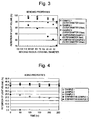
- FIG. 1 A first embodiment of the present invention will be explained with reference to Figs. 1 through 4 .
- the first embodiment will be shown by "Example 1", “Example 2" and “Example 3" as discussed below.
- the light transmitting material 1 is comprising a tubular clad material 3, and a core material 5 which has been incorporated and placed inside the tubular clad material 3.
- the reference examples are not in accordance with the invention.
- polymer polyol serving as the core material 5 10 g of polyoxypropylene triol and 10 g of polyoxypropylene diol were used, and as a polyfunctional compound having reactivity with a hydroxyl group, 20 g of hexamethylene diisocyanate was used. Further, as a tube serving as the tubular clad material 3, an FEP tube of which outer diameter was 3.6 mm and of which length was 1.3 m was used. The mixture of the above core material 5 was filled in the above tubular clad material 3, and hardened by heat at 90°C, and thereafter, the both ends were cut, whereby the light transmitting material 1, having the length of 1 m, could be obtained.
- a polymer polyol serving as the core material 5 10 g of polyoxypropylene triol and 10 g of polyoxypropylene diol were used, and as a polyfunctional compound having reactivity with a hydroxyl group having isocyanurate bond, 20 g of Coronate HX (manufactured by Nippon Polyurethane Industry Co., Ltd.) was used. Further, as a tube serving as the tubular clad material 3, an FEP tube of which outer diameter was 3.6 mm and of which length was 1.3 m was used. The mixture of the above core material 5 was filled in the above tubular clad material 3, and hardened by heat at 90°C, and thereafter, the both ends were cut, whereby the light transmitting material 1, having the length of 1 m, could be obtained.
- a polymer polyol serving as the core material 5 20 g of polyoxypropylene triol was used, and as a polyfunctional compound having reactivity with a hydroxyl group having isocyanurate bond, 20 g of Coronate HX (manufactured by Nippon Polyurethane Industry Co., Ltd.) was used. Further, as a tube serving as the tubular clad material 3, an FEP tube of which outer diameter was 3.6 mm and of which length was 1.3 m was used. The mixture of the above core material 5 was filled in the above tubular clad material 3, and hardened by heat at 90°C, and thereafter, the both ends were cut, whereby the light transmitting material 1, having the length of 1 m, could be obtained.
- a commercial light transmitting material of which core material and tubular clad material were both made of PMMA plastic material, and of which outer diameter was 3 mm and of which length was 1.3 m, was provided, and the both ends were cut, whereby the commercial light transmitting material, having the length of 1 m, could be obtained.
- a core material As a core material, a commercial two liquid mixture type of polyorgano siloxane was used, and as a tube serving as the tubular clad material, an FEP tube of which outer diameter was 3.6 mm and of which length was 1.3 m was used.
- the above core material was filled in the above tubular clad material, and hardened by heat, and thereafter, the both ends were cut, whereby the light transmitting material having the length of 1 m could be obtained.
- the retention of light volume of each sample was measured, by placing each sample linearly.
- the retention of light volume was calculated by using the following formula, after measuring the light volume emitting out of a white LED, and also measuring the light volume emitting out of one end of the light transmitting material 1 as the subject of measurement, when the white LED was incident in the other end thereof, by using an illuminometer:
- Retention of light volume % Light volume emitting out of light transmitting material / Light volume of LED ⁇ 100
- Each sample was left in a high-temperature and high-humidity bath at 80°C and 95 % for a predetermined time. Thereafter, the sample was collected and left at room temperature for 30 minutes, and the change of retention of light volume due to the change of time was measured in that state. The result is as per shown in Fig. 4 .
- each of the examples 1, 2 and 3 had the remarkable excellent flexibility as compared with the comparative example 1.
- each of the examples 1, 2 and 3 had the remarkable excellent retention of light volume as compared with the comparative examples 1 and 2.
- polymer polyol serving as the core material 5 10 g of polyoxypropylene triol and 10 g of polyoxypropylene diol were used, and as a polyfunctional compound having reactivity with a hydroxyl group, 20 g of hexamethylene diisocyanate was used. Further, as a tube serving as the tubular clad material 3, an FEP tube of which outer diameter was 3.6 mm was used. The mixture of the above core material 5 was filled in the above tubular clad material 3, and hardened by heat at 90°C, and thereafter, the both ends were cut, whereby the light transmitting material 1 could be obtained.
- example 4 is equivalent to the example 1 of the first embodiment of the present invention.
- polymer polyol serving as the core material 5 12 g of polyoxypropylene triol and 12 g of polyoxypropylene diol were used, and as a polyfunctional compound having reactivity with a hydroxyl group, 13 g of Cosmonate NBDI (manufactured by Mitsui Takeda Chemicals, Inc.) was used. Further, as a tube serving as the tubular clad material 3, an FEP tube of which outer diameter was 3.6 mm was used. The mixture of the above core material 5 was filled in the above tubular clad material 3, and hardened by heat at 90°C, and thereafter, the both ends were cut, whereby the light transmitting material 1 could be obtained.
- polymer polyol serving as the core material 5 10 g of polyoxypropylene triol and 10 g of polyoxypropylene diol were used, and as a polyfunctional compound having reactivity with a hydroxyl group having isocyanurate bond, 20 g of Coronate HX (manufactured by Nippon Polyurethane Industry Co., Ltd.) was used. Further, as a tube serving as the tubular clad material 3, an FEP tube of which outer diameter was 3.6 mm was used. The mixture of the above core material 5 was filled in the above tubular clad material 3, and hardened by heat at 90°C, and thereafter, the both ends were cut, whereby the light transmitting material 1 could be obtained.
- Coronate HX manufactured by Nippon Polyurethane Industry Co., Ltd.
- example 6 is equivalent to the example 2 of the first embodiment of the present invention.
- a polymer polyol serving as the core material 5 20 g of polyoxypropylene triol was used, and as a polyfunctional compound having reactivity with a hydroxyl group having isocyanurate bond, 20 g of Coronate HX (manufactured by Nippon Polyurethane Industry Co., Ltd.) was used. Further, as a tube serving as the tubular clad material 3, an FEP tube of which outer diameter was 3.6 mm was used. The mixture of the above core material 5 was filled in the above tubular clad material 3, and hardened by heat at 90°C, and thereafter, the both ends were cut, whereby the light transmitting material 1 could be obtained.
- example 7 is equivalent to the example 3 of the first embodiment of the present invention.
- a commercial light transmitting material of which core material and clad material were both made of PMMA plastic material, and of which outer diameter was 3 mm, was provided, and the both ends were cut, whereby the commercial light transmitting material could be obtained.
- the comparative example 3 is equivalent to the comparative example 1 of the first embodiment of the present invention.
- a core material As a core material, a commercial two-liquid mixture type of polyorgano siloxane was used, and as a tube serving as the tubular clad material, an FEP tube of which outer diameter was 3.6 mm was used.
- the above core material was filled in the above tubular clad material, and hardened by heat, and thereafter, the both ends were cut, whereby the light transmitting material could be obtained.
- the comparative example 4 is equivalent to the comparative example 2 of the first embodiment of the present invention.
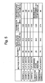
- the transmission loss value of each sample was measured according to 3 m - 1 m cut back method, by using a white LED as a light source, the result is as per shown in Fig. 5 .
- each of the examples 4, 5, 6 and 7 had the remarkable excellent flexibility as compared with the comparative example 3.
- the transmission loss values according to the examples 4, 5, 6 and 7, each had the value of not more than 1.0 dB/m, thus showing the sufficient light transmitting properties.
- each of the examples 4, 5, 6 and 7 had the excellent retention of light volume as compared with the comparative example 3.
- polymer polyol serving as the core material 5 10 g of polyoxypropylene triol and 10 g of polyoxypropylene diol were used.
- polyfunctional compound having reactivity with a hydroxyl group 20 g of hexamethylene diisocyanate was used.
- tube serving as the tubular clad material 3 an FEP tube of which outer diameter was 10.6 mm was used.
- particles 0.01 g of glass beads, each of which average diameter was 5 ⁇ m, were used.
- the mixture of the fluid polymer polyol and the polyfunctional compound having reactivity with the hydroxyl group, with the particles, was filled in the above tubular clad material 3, and non-fluidized by heat at 100°C, and thereafter, the both ends were cut, whereby the light transmitting material (light scattering material) 1 could be obtained.
- polymer polyol serving as the core material 5 12 g of polyoxypropylene triol and 12 g of polyoxypropylene diol were used.
- a polyfunctional compound having reactivity with a hydroxyl group 13 g of Cosmonate NBDI (manufactured by Mitsui Takeda Chemicals, Inc.) was used.
- a tube serving as the tubular clad material 3 an FEP tube of which outer diameter was 10.6 mm was used. Further, as for particles, 0.01 g of glass beads, each of which average diameter was 5 ⁇ m, were used.
- the mixture of the fluid polymer polyol and the polyfunctional compound having reactivity with the hydroxyl group, with the particles, was filled in the above tubular clad material 3, and non-fluidized by heat at 100°C, and thereafter, the both ends were cut, whereby the light transmitting material (light scattering material) 1 could be obtained.
- polymer polyol serving as the core material 5 10 g of polyoxypropylene triol and 10 g of polyoxypropylene diol were used.
- a polyfunctional compound having reactivity with a hydroxyl group, having isocyanurate bond 20 g of Coronate HX (manufactured by Nippon Polyurethane Industry Co., Ltd.) was used.
- a tube serving as the tubular clad material 3 an FEP tube of which outer diameter was 10.6 mm was used. Further, as for particles, 0.01 g of glass beads, each of which average diameter was 5 ⁇ m, were used.
- the mixture of the fluid polymer polyol and the polyfunctional compound having reactivity with the hydroxyl group, with the particles, was filled in the above tubular clad material 3, and non-fluidized by heat at 100°C, and thereafter, the both ends were cut, whereby the light transmitting material (light scattering material) 1 could be obtained.
- a polymer polyol serving as the core material 5 20 g of polyoxypropylene triol was used, and as a polyfunctional compound having reactivity with a hydroxyl group having isocyanurate bond, 20 g of Coronate HX (manufactured by Nippon Polyurethane Industry Co., Ltd.) was used.
- a tube serving as the tubular clad material 3 an FEP tube of which outer diameter was 10.6 mm was used. Further, as for particles, 0.01 g of glass beads, each of which average diameter was 5 ⁇ m, were used.
- the mixture of the fluid polymer polyol and the polyfunctional compound having reactivity with the hydroxyl group, with the particles, was filled in the above tubular clad material 3, and non-fluidized by heat at 100°C, and thereafter, the both ends were cut, whereby the light transmitting material (light scattering material) 1 could be obtained.
- core material a PMMA plastic material was used.
- clad material an FEP tube of which outer diameter was 10.6 mm as used.
- particles 0.01 g of glass beads, each of which average diameter was 5 ⁇ m, were used. The mixture of the core material with the particles was filled in the above tube, and hardened by heat, and thereafter, the both ends were cut, whereby the light transmitting material (light scattering material) could be obtained.
- a core material a commercial two-liquid mixture type of polyorgano siloxane was used.
- an FEP tube of which outer diameter was 10.6 mm was used.
- particles 0.01 g of glass beads, each of which average diameter was 5 ⁇ m, were used. The mixture of the core material with the particles was filled in the above tube, and hardened by heat, and thereafter, the both ends were cut, whereby the light transmitting material (light scattering material) could be obtained.
- the structure was substantially the same as that of the example 10, except for particles, for which 0.01 g of glass beads, each of which average diameter was 70 ⁇ m, were used.
- the light transmitting material light scattering material
- the side face light emission volume of each sample was measured, by placing each sample linearly.
- a white LED serving as a light source was used as the 0-point, thus the side face light emission volume was obtained, by measuring the side face light emission volume at a predetermined position, by using an illuminometer. The result is as per shown in Fig. 10 .
- the side face light emission volumes of each sample were measured, by placing each sample linearly.
- a white LED serving as a light source was used as the 0-point, thus the side face light emission volumes were obtained, by measuring the side face light emission volumes on the same circumferential face at angles from 0° to 270° , by every angle of 90° , from the distance of 200 mm, by using an illuminometer. The result is as per shown in Fig. 9 .
- Each sample having the length of 0.4 mm, was left in the warm water at 60°C for a predetermined time. Thereafter, the sample was collected and left at room temperature for 30 minutes. Then the each sample was placed linearly, and the change rate of light emission volume, in regard to the side face light emission volume, was measured in that state. The change rate of light emission volume was calculated,by measuring the side face light emission volume at the position 200 mm away from a white LED serving as a light source placed at the 0-point, by using an illuminometer. The result is as per shown in Fig. 11 .
- each of the examples 8, 9, 10 and 11 had the remarkable excellent flexibility as compared with the comparative example 5.
- the examples 8, 9, 10 and 11 each had the excellent side face light emission volume irrespective of the distance from the light source, and showed the excellent side face light emission property.
- the example 9, for which alicyclic polyisocyanate was used as the polyfunctional compound having reactivity with the hydroxyl group, serving as the core material and the examples 10 and 11, for which the polyfunctional compound having reactivity with the hydroxyl group, having isocyanurate bond was used as that serving as the core material, respectively indicated especially excellent side face light emission property.
- the uniform side face light emission volume could not be obtained on the same circumferential face.
- the side face light emission properties (aging properties), according to the examples 8, 9, 10 and 11, there was almost no decrease of side face light emission volume in the warm water, and the excellent side face light emission property could be stably maintained for a long period of time.
- the examples 10 and 11, for which the polyfunctional compound having reactivity with the hydroxyl group, having isocyanurate bond was used as that serving as the core material, respectively indicated especially excellent aging properties.
- the comparative example 6 in which a polyorgano siloxane was used as the core material the material become clouded after 50 hours, and it became impossible to measure the measurement of side face light emission volume.
- a light transmitting material (light scattering material), which can be formed and placed at any arbitrary position easily, because of the soft and flexible property thereof, even if the diameter is increased, which has no risk of being damaged because of the good impact resistance, which almost has no adverse effect of decrease of side face light emission volume under high temperature and high humidity or in the warm water, and which is capable of stably maintaining an excellent side face light emission property for a long period of time, at a lower production cost.
- a polymer polyol serving as the core material 5 10 g of polyoxypropylene triol and 10 g of polyoxypropylene diol were used, and as a polyfunctional compound having reactivity with a hydroxyl group, 20 g of hexamethylene diisocyanate was used.
- tubes serving as the tubular clad material 3 two FEP tubes, of which respective size was, length 0.6 m, outer diameter 3.0 mm, and inner diameter 2.6 mm, were used.
- the mixture of the above core material 5 was filled in the tubular clad materials 3.
- optical device 7 made of PMMA and having the size of 10 mm of length and 2.7 mm of outer diameter, and the both ends of the optical device 7 were inserted into these tubular clad materials 3, respectively filled with the above liquid core material 5, for the depth of about 5 mm. They were hardened by heat at 100°C, and thereafter, two ends of the light transmitting material 1, not the ends into which the optical device 7 had been inserted, were cut, whereby the light transmitting material 1, having the length of 1 m and being connected to the optical device 7, could be obtained.
- a polymer polyol serving as the core material 5 12 g of polyoxypropylene triol and 12 g of polyoxypropylene diol were used, and as a polyfunctional compound having reactivity with a hydroxyl group, 13 g of Cosmonate NBDI (manufactured by Mitsui Takeda Chemicals, Inc.) was used.
- tubes serving as the tubular clad material 3 two FEP tubes, of which respective size was, length 0.6 m, outer diameter 3.0 mm, and inner diameter 2.6 mm, were used.
- the mixture of the above core material 5 was filled in the tubular clad materials 3.
- optical device 7 made of PMMA and having the size of 10 mm of length and 2.7 mm of outer diameter, and the both ends of the optical device 7 were inserted into these tubular clad materials 3, respectively filled with the above liquid core material 5, for the depth of about 5 mm. They were hardened by heat at 100°C, and thereafter, two ends of the light transmitting material 1, not the ends into which the optical device 7 had been inserted, were cut, whereby the light transmitting material 1, having the length of 1 m and being connected to the optical device 7, could be obtained.
- a polymer polyol serving as the core material 5 10 g of polyoxypropylene triol and 10 g of polyoxypropylene diol were used, and as a polyfunctional compound having reactivity with a hydroxyl group, having isocyanurate bond, 20 g of Coronate HX (manufactured by Nippon Polyurethane Industry Co., Ltd.) was used.
- tubes serving as the tubular clad material 3 two FEP tubes, of which respective size was, length 0.6 m, outer diameter 3.0 mm, and inner diameter 2.6 mm, were used.
- the mixture of the above core material 5 was filled in the tubular clad materials 3.
- optical device 7 made of PMMA and having the size of 10 mm of length and 2.7 mm of outer diameter, and the both ends of the optical device 7 were inserted into these tubular clad materials 3, respectively filled with the above liquid core material 5, for the depth of about 5 mm. They were hardened by heat at 100°C, and thereafter, two ends of the light transmitting material 1, not the ends into which the optical device 7 had been inserted, were cut, whereby the light transmitting material 1, having the length of 1 m and being connected to the optical device 7, could be obtained.
- a polymer polyol serving as the core material 5 20 g of polyoxypropylene triol was used, and as a polyfunctional compound having reactivity with a hydroxyl group, having isocyanurate bond, 20 g of Coronate HX (manufactured by Nippon Polyurethane Industry Co., Ltd.) was used.
- tubes serving as the tubular clad material 3 two FEP tubes, of which respective size was, length 0.6 m, outer diameter 3.0 mm, and inner diameter 2.6 mm, were used.
- the mixture of the above core material 5 was filled in the tubular clad materials 3.
- optical device 7 made of PMMA and having the size of 10 mm of length and 2.7 mm of outer diameter, and the both ends of the optical device 7 were inserted into these tubular clad materials 3, respectively filled with the above liquid core material 5, for the depth of about 5 mm. They were hardened by heat at 100°C, and thereafter, two ends of the light transmitting material 1, not the ends into which the optical device 7 had been inserted, were cut, whereby the light transmitting material 1, having the length of 1 m and being connected to the optical device 7, could be obtained.
- Two commercial light transmitting materials each of which core material and clad -material were--both made of PMMA plastic material, and each of which length was 0.5 m and outer diameter was 3.0 mm, was provided. These light transmitting materials were connected by using a commercial adhesive, with a cylindrical shape of optical device, made of PMMA and having the size of 10 mm of length and 3.0 mm of outer diameter. Thus the light transmitting material, having the length of 1 m and being connected to the optical device, could be obtained.
- a commercial two-liquid mixture type of polyorgano siloxane was used as a core material.
- tubes serving as the tubular clad material two FEP tubes, of which respective size was, length 0.6 m, outer diameter 3.0 mm, and inner diameter 2.6 mm, were used.
- the mixture of the above core material was filled in the tubular clad materials.
- polymer polyol serving as the core material 10 g of polyoxypropylene triol and 10 g of polyoxypropylene diol were used, and as a polyfunctional compound having reactivity with a hydroxyl group, 20 g of hexamethylene diisocyanate was used.
- a tube serving as the tubular clad material an FEP tube, of which size was, length 0.6 m, outer diameter 3.0 mm,and inner diameter 2.6 mm, was used.
- the mixture of the above core material was filled in the tubular clad material, and hardened by heat at 100°C. Thereafter, the both ends were cut, whereby the light transmitting material, of which length was 0.5 m, could be obtained.
- the light volume of each sample was measured.
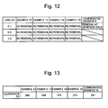
- the light emitted from a white LED was incident in one end of each sample, and then the light volume, emitted from the other end of each sample, by going through the connecting part, was measured by using an illuminometer. The result is as per shown in Fig. 13 .
- the examples 12, 13, 14 and 15 there was almost no decrease of light volume in the warm water, and the excellent light transmission property could be stably maintained for a long period of time.
- the example 13, for which alicyclic polyisocyanate was used as the polyfunctional compound having reactivity with the hydroxyl group, serving as the core material and the examples 14 and 15, for which the polyfunctional compound having reactivity with the hydroxyl group, having isocyanurate bond was used as that serving as the core material, respectively indicated especially excellent aging properties.
- the comparative example 9 in which a polyorgano siloxane was used as the core material the material become clouded after 50 hours, and it became impossible to measure the measurement of side face light emission volume.
- This embodiment of the present invention is of course not limited to the examples as discussed above.
- the dispersed particles were not used in the above examples, when the dispersed particles are provided, for any of the light transmitting material or the optical device, or for the both of them, it is possible to provide the sample in which the side face light emission can be obtained at the dispersed particles portion.
- the present invention is useful as for the following points.
- a light transmitting material suitable for, light signal transmission such as for in-vehicle wiring, mobile wiring and FA device wiring, optical sensors such as liquid surface level sensors or pressure sensors, image guides such as for endoscopes, light guides such as for decorative displays, home electric appliances, optical devices, outdoor signages, etc.
- optical sensors such as liquid surface level sensors or pressure sensors
- image guides such as for endoscopes
- light guides such as for decorative displays, home electric appliances, optical devices, outdoor signages, etc.
- a light transmitting material (light scattering material), which can be formed and placed at an arbitrary position easily, because of the soft and flexible property even if the diameter is increased, which has no risk of being damaged because of the good impact resistance, which has almost no adverse effect of decrease of side face light emission volume under high temperature and high humidity or in the warm water, and which can stably maintain an excellent side face light emission property for a long period of time, and it is also possible to provide a method for manufacturing such a light transmitting material (light scattering material).
Landscapes
- Physics & Mathematics (AREA)
- General Physics & Mathematics (AREA)
- Optics & Photonics (AREA)
- Optical Fibers, Optical Fiber Cores, And Optical Fiber Bundles (AREA)
- Combinations Of Printed Boards (AREA)
Abstract
Description
- The present invention relates to a light transmitting material suitable for, light signal transmission such as for in-vehicle wiring, mobile wiring and FA device wiring, optical sensors such as liquid surface level sensors or pressure sensors, image guides such as for endoscopes, light guides such as for decorative displays, home electric appliances, optical devices, outdoor signages, etc. More particularly, the present invention relates to the light transmitting material, characterized by having almost no adverse effect of decrease of light volume or increase of transmission loss value when being bent, having almost no adverse effect of decrease of light volume or increase of transmission loss value under high temperature and high humidity or in the warm water, being free from deformation when exposed in high temperature in a moment, and being capable of stably maintaining an excellent light transmitting property for a long period of time, having sufficient flexibility even if the diameter is increased. The present invention also relates to a method for manufacturing such a light transmitting material at a lower production cost.
- Further, the present invention also relates to a light transmitting material (light scattering material), characterized by easy and arbitrary forming to be placed at any position because of the soft and flexible property even if the diameter is increased, having no risk of being damaged because of the good impact resistance, having almost no adverse effect of decrease of side face light emission volume under high temperature and high humidity or in the warm water, and being capable of stably maintaining an excellent side face light emission property for a long period of time. The present invention also relates to a method for manufacturing such a light transmitting material (light scattering material) at a lower production cost.
- Further, the present invention also relates to a structure connecting light transmitting material and optical device. More particularly, the present invention relates to such a structure, characterized by having small adverse effect of decrease of light volume or increase of transmission loss value at the connecting part, having practically sufficient connecting strength, and having almost no adverse effect of decrease of light volume or increase of transmission loss value under high temperature and high humidity or in the warm water.
- First, several types of conventional light transmitting material will be reviewed, which are used for the light emission at the end of these materials.
- In regard to light transmitting materials capable of being used, e.g. for light signal transmission such as for in-vehicle wiring; mobile wiring and FA device wiring, optical sensors such as liquid surface level sensors or pressure sensors, image guides such as for endoscopes, light guides such as for decorative displays, home electric appliances, optical devices, outdoor signages, etc., there have been provided several materials as below.
- There has been a material, of which core material and clad material are both composed of inorganic glass material such as silica glass or multicomponent glass.
- There has also been a material, of which core material and clad material are both composed of PMMA (polymethyl methacrylate) plastic material.
- There has also been a material, wherein a tubular clad material having small refractive index, such as silicone polymer or fluorocarbon polymer, is used, and a plastic material such as organo-polysiloxane having higher refractive index than that of the tubular clad material and serving as a core material, is filled and hardened in that tubular clad material.
- There has also been a material, wherein a tubular clad material having small refractive index, such as silicone polymer or fluorocarbon polymer, is used, and a liquid or fluid transparent material having higher refractive index than that of the tubular clad material and serving as a core material, is filled and sealed in that tubular clad material (See Japanese Unexamined Patent Publication No.
Hei 11-190808 - Further, there has also been a material, of which clad material is composed of fluorocarbon polymer, etc., and of which core material is composed of polycarbonate resin or norbornene resin, etc., having higher refractive index than that of the clad material (See Japanese Unexamined Patent Publication No.
2000-275448 - However, the conventional light transmitting materials discussed as above have the following problems.
- First, in the case of a light transmitting material of which core material and clad material are both composed of inorganic glass material, when this type of light transmitting material is used e.g. as a light guide, this material would express the good light transmitting property, having almost no decrease of light volume for a wide frequency. However, because a bundle of a large number of very thin light transmitting materials (each of which outer diameter is about 10 µm) is used as a single light transmitting material, it would require the bundling process, as well as bundling components such as bundling tubes or bundling metal fittings, which would result in higher production cost.
- Second, the reference is made to a light transmitting material of which core material and clad material are both composed of PMMA plastic material. In the case of this light transmitting material, the transmission loss value is good (about 0.2 dB/m). However, the wiring workability is poor due to insufficient flexibility, and when being bent and used, the material would present a considerable adverse effect of decrease of light volume and increase of transmission loss value, and accordingly, the using purpose of this material is considerably limited. Further, this light transmitting material is very hard, and when the end faces are merely cut, the material would present a considerable adverse effect of decrease of light volume and increase of transmission loss value, and accordingly it is necessary to polish the both end faces, which would result in higher production cost.
- Third, the reference is made to a light transmitting material wherein a plastic material such as organo-polysiloxane, serving as a core material, is filled and hardened in a tubular clad material. This light transmitting material has the transmission loss value at about 1.0 dB/m, and in normal state, this type of material has the good light transmission property with almost no adverse effect of decrease of light volume or increase of transmission loss value. However, the material would become clouded under high temperature and high humidity or in the warm water, and would present a considerable adverse effect of decrease of light volume and increase of transmission loss value. To cope with these problems, for example with reference to Japanese Patent No.
3024475 - Fourth, in the case of a light transmitting material wherein a liquid or fluid transparent material serving as a core material is filled and sealed in a tubular clad material, it is necessary to apply laborious end sealing process to the both ends of material, such as sealing by sealer and adhering to the clad material, or covering the clad material by metal sleeve so that the both ends of the sleeve may be tightly fastened, and consequently, the production cost would become higher. In addition, since the sealing of the both ends is required, when the material is actually used, it is impossible to cut the material at a desired length, which would result in a very limited using purpose.
- Further, in the case of a light transmitting material, of which clad material is composed of fluorocarbon polymer, etc., and of which core material is composed of polycarbonate resin or norbornene resin, etc., the transmission loss value is about 1.0 dB/m. However, for the purpose of preventing from becoming clouded under high temperature and high humidity or in the warm water, as suggested in Japanese Unexamined Patent Publication No.
2000-275448 - Now, several types of conventional light transmitting material will also be reviewed, which are used for the light emission from the side of these materials.
- For example, neon tubes or fluorescent tubes are used as a light source for decorative displays, home electric appliances, outdoor signages and various illumination devices. However, these devices would require high voltage, and therefore, if they are used in the water or in any water-affected place such as being exposed in the rain, there would be a risk of electric shock or electric leakage. In addition, since these tubes are made of glass and may be broken easily, which would also result in a very limited using purpose.
- Therefore, recently, as the alternative material, there have been provided a various type of side-emitting optical fibers, wherein, the light is incident in at least any one end of the optical fiber, comprising a core and a clad, in the longitudinal direction, and the light is emitted in the circumferential direction (from the side face) of the core and the clad.
- For example, with reference to Japanese Unexamined Patent Publication No.
2000-131529 - With reference to Japanese Unexamined Patent Publication No.
2000-321444 - However, the conventional light transmitting materials discussed as above have the following problems.
- First, in the case of light transmitting tube disclosed as Japanese Unexamined Patent Publication No.
2000-131529 - Second, in the case of optical fiber disclosed as Japanese Unexamined Patent Publication No.
2000-321444 3024475 - Now, several types of conventional structure between light transmitting material and optical device will be reviewed.
- When light transmitting material is used, the technology to connect the light transmitting material with optical device is required for the purpose of improving the convenience, and various technologies have been investigated. In regard to light transmitting material and optical device, there have been investigated those comprising PMMA plastic material, or those comprising silicone polymer, etc.
- For the purpose of connecting these light transmitting material with optical device, there has been investigated the following methods. When connecting a light transmitting material with an optical device, both comprising PMMA plastic material, it has been investigated that, the end face of the light transmitting material is in contact with the end face of the optical device, or the each end face has been formed to be a substantially half round section face for a predetermined length, and is in contact with each other,and thereafter, the contact face is connected by adhesive or ultrasonic welding machine. Further, reference is made to a method for connecting, in the case that one of the light transmitting material and the optical device is made of PMMA plastic material, and that the other is made of silicone polymer. In this method, it is possible to connect liquid silicone polymer before the hardening reaction with the optical device made of PMMA plastic material, in which the silicone polymer may serve as adhesive by hardening reaction itself. When connecting a light transmitting material with an optical device, both comprising silicone polymer, any of the above method may be used.
- When connecting a light transmitting material with an optical device, both comprising PMMA plastic material, it is understood that, in regard to the structure of connecting part, the contact face between the core material of the light transmitting material and the core material of the optical device is not covered by the clad material of the light transmitting material. On the other hand, when connecting a light transmitting material with an optical device, any of which is made of PMMA plastic and the other of which is made of silicone polymer, or when connecting a light transmitting material with an optical device, both of which are made of silicone polymer, it is understood that, in regard to the structure of connecting part, the contact face between the core material of the light transmitting material and the core material of the optical device is covered by the clad material of the light transmitting material.
- However, the conventional connecting structure discussed as above have the following problems. With reference to a combination of light transmitting material with material of optical device, firstly, when PMMA plastic material is used for both the light transmitting material and the optical device, the contact face between the core material of the light transmitting material and the core material of the optical device is not covered by the clad material of the light transmitting material, in other words, the core material and the clad material are positioned on the same plane at the contact face. Consequently, with reference to the contact face on which the scatter of light would easily occur, when the scatter of light occurs at the contact face of the core material, the scattering light at the contact face of the core material would easily go out of the contact face of the clad material, and further, the scatter of light would further occur easily at the clad material, which would enhance decrease of light volume and increase of transmission loss value.
- When the contact face between the light transmitting material and the optical device is not covered by the clad material of the light transmitting material, as compared with the case in which the contact face of the clad material is not positioned on the same plane as the contact face of the core material, the contact area would become smaller, thus it is difficult to obtain the sufficient connecting strength. Further, if the sufficient flexibility is not provided for any of the light transmitting material or the optical device, or for both of them, when any force such as warping is applied thereto, it will be impossible to absorb such a warping force,etc.by any flexible part, which might-cause-the destruction of contact face. Consequently, it will be difficult to simply obtain practically sufficient connecting strength, and the destruction might occur easily, which would pose the problem of difficulty for practical application.
- Further, in the case that one of the light transmitting material and the optical device is made of, or the both of them are made of silicone polymer, when one of them has become in contact with the other before the hardening reaction of silicone polymer, they will be connected with each other, because of the silicone polymer serving as adhesive by hardening reaction itself. This connecting structure has flexibility, thus it is possible to obtain practically sufficient connecting strength. However, when silicone polymer is used, there would be the problem of becoming clouded under high temperature and high humidity or in the warm water, which would cause the adverse effect of decrease of light volume or increase of transmission loss value, and it will be impossible to carry out the function as light transmitting material or optical device.
-
US-A-4909597 discloses an optical waveguide having a high degree of flexibility. The optical waveguide comprises a core comprising a flexible thermoplastic aliphatic segmented polyurethane; and a clad comprising a flexible material which adheres to the core and which possesses a lower refractive index than the core. The flexible thermoplastic aliphatic-segmented polyurethane is formed from reactions between glycols, diisocyanates, and chain extenders. Examples of preferred glycols comprise poly(oxypropyleneoxyethylene)-glycols and poly(oxybutyleneoxyethylene)glycols. Examples of preferred diisocyanates include compounds having an aliphatic and/or cycloaliphatic structure, such as polymethylene diisocyanates, or cyclohexane-1,4-diisocyanate. Examples of preferred clad materials include polysiloxanes. - It is an object of the present invention to provide a light transmitting material, characterized by having almost no adverse effect of decrease of light volume or increase of transmission loss value when being bent, having almost no adverse effect of decrease of light volume or increase of transmission loss value under high temperature and high humidity or in the warm water, being free from deformation when exposed in high temperature in a moment, and being capable of stably maintaining an excellent light transmitting property for a long period of time, having sufficient flexibility even if the diameter is increased. It is also an object of the present invention to provide a method for manufacturing such a light transmitting material at a lower production cost.
- Further, it is another object of the present invention to provide a light transmitting material (light scattering material), characterized by easy and arbitrary forming to be placed at any position because of the soft and flexible property even if the diameter is increased, having no risk of being damaged because of the good impact resistance, having almost no adverse effect of decrease of side face light emission volume under high temperature and high humidity or in the warm water, and being capable of stably maintaining an excellent side face light emission property for a long period of time. It is also another object of the present invention to provide a method for manufacturing such a light transmitting material (light scattering material) at a lower production cost.
- Further, it is also another object of the present invention to provide a structure connecting light transmitting material and optical device, characterized by having small adverse effect of decrease of light volume or increase of transmission loss value at the connecting part, having practically sufficient connecting strength, and having almost no adverse effect of decrease of light volume or increase of transmission loss value under high temperature and high humidity or in the warm water.
- The present invention provides a light transmitting material comprising, a tubular clad material, and an amorphous core material incorporated in said tubular clad material and having higher refractive index than that of said tubular clad material, characterized in that,
said amorphous core material has an ingredient of at least a polymer comprising a polymer polyol and a polyfunctional compound having reactivity with a hydroxyl group, said polyfunctional compound having reactivity with said hydroxyl group having a functional group derived from isocyanate group. - The invention further provides a structure connecting said light transmitting material and an optical device, and said optical device being provided with at least a core material having higher refractive index than that of said tubular clad material of said light transmitting material, characterized in that:
- a contact face of said amorphous core material of said light transmitting material with said core material of said optical device is covered by said tubular clad material of said light transmitting material; and
- the difference in refractive index from said core material of said optical device is within +/- 0.1.
- Moreover, the invention provides a method for manufacturing light transmitting material, comprising steps of.
- filling at least a mixture of a fluid polymer polyol with a polyfunctional compound having reactivity with a hydroxyl group, said polyfunctional compound having reactivity with said hydroxyl group having a functional group derived from isocyanate group, in a tubular clad material;
- reacting the filled polymer polyol with polyfunctional compound having reactivity with said hydroxyl group; and
- whereby obtaining a non-fluidized light transmitting material.
- The invention further provides a method for manufacturing light transmitting material, comprising steps of
- filling at least, a fluid polymer polyol and a polyfunctional compound having reactivity with a hydroxyl group, said polyfunctional compound having reactivity with said hydroxyl group having a functional group derived from isocyanate group, and particles, in a tubular clad material;
- reacting the filled polymer polyol with polyfunctional compound having reactivity with said hydroxyl group; and
- whereby obtaining a non-fluidized light transmitting material.
- Preferred embodiments of the present invention are set forth in the sub-claims.
- With reference to material serving as a tubular clad material according to the present invention, it is not limited as long as the material is flexible and capable of being formed into tubular shape, such as plastic or elastomer. For example, the material may be polyethylene, polyamide, polyvinyl chloride, silicone resin, natural rubber, fluorocarbon polymer such as polytetrafluroethylene (PTFE), tetrafluoroethylene - hexafluoropropylene copolymer (FEP), tetrafluoroethylene - perfluoroalkoxyethylene (PFA), polychlorotrifluoroethylene (PCTFE), tetrafluoroethylene - ethylene copolymer (ETFE), polyvinylidenefluoride, vinylidenefluoride - hexafluoropropylene copolymer, tetrafluoroethylene propylene rubber, tetrafluoroethylene - hexafluoropropylene - vinylidenefluoride copolymer (THV), polyperfluoro butenil vinyl ether, TFE - perfluoro dimethyl dioxolane copolymer, fluoroalkyl methacrylate copolymer, or fluorocarbon thermoplastic elastomer. They may be used solely, or by blending two or more materials. Among these materials, it is preferable to use FEP, PFA, vinylidenefluoride - hexafluoropropylene copolymer, THV, polyperfluoro butenil vinyl ether, TFE - perfluoro dimethyl dioxolane copolymer, and fluorocarbon thermoplastic elastomer, because of their good transparency and mechanical property.
- According to the present invention, these materials are formed to be a tubular shape by known extrusion method, serving as a tubular clad material.
- The core material must be made of any material of which refractive index is higher than that of the tubular clad material as discussed above. According to the present invention, polymer of a polymer polyol with a polyfunctional compound having reactivity with a hydroxyl group is used as one of the ingredients. As for polymer polyol, the example may be, polyoxypropylene polyol, polyethylene glycol, polyoxyalkylene polyol such as polytetramethylene ether glycol, modified polyoxyalkylene polyol such as urethane modified polyether polyol or silicone modified polyether polyol, polyether ester copolymer polyol, polycarbonate polyol, or the copolymer or mixture thereof. Among these materials, it is preferable to use polyoxypropylene polyol because of the good light transmission property under high temperature and high humidity or in the warm water.
- As for a polyfunctional compound having reactivity with a hydroxyl group, compound having functional group derived from isocyanate group is used. As for compound having functional group derived from isocyanate group, the example may be, blocked isocyanate in which isocyanate has been blocked by known art such as lactam, or compound having isocyanurate in which isocyanate group has been multiplied by known art. They may be used solely, or by blending two or more materials. A compound having functional group derived from isocyanate group is used because of the good light transmission property under high temperature and high humidity or in the warm water. As for compound having functional group derived from isocyanate group, it is more preferable to use that having isocyanurate bond.
- According to the present invention, light transmitting material is manufactured by using the tubular clad material and the core material as discussed above, in the following method.
- First, at least the polymer of a fluid polymer polyol with a polyfunctional compound having reactivity with a hydroxyl group has been filled inside the tubular clad material.
- In this connection, the term "at least" means that it is sufficient to have the polymer of the polymer polyol with the polyfunctional compound having reactivity with the hydroxyl group as one of the ingredients, and it is of course assumed that any third ingredient may be included.
- In regard to the method for filling the mixture of the fluid polymer polyol with the polyfunctional compound having reactivity with the hydroxyl group inside the tubular clad material, it is possible, for example, to use vacuum pump or tube pump. In addition, as another method, it is also possible to fill the fluid core material at the same time of manufacturing the tubular clad material by extrusion method. With this method, it is possible to manufacture a long size of light transmitting material continuously.
- Thereafter, the fluid polymer polyol and the polyfunctional compound having reactivity with the hydroxyl group are reacted, for example by heat, to be non-fluidized state.
- In this connection, the term "non-fluidized" includes the case of solid material and the case of partially incorporating gel material. Further, according to the present invention, the term "at least partially incorporating gel material" includes three cases, i.e. the case of gel and solid materials, the case of gel and liquid materials, and the case of entirely gel material. When the part of gel material is incorporated, the transparency and flexibility will improve.
- It is also possible to the part of generate gel material by introducing any third ingredient. In other words, since the third ingredient will not be reacted, that part will remain as the part of gel material.
- In regard to particles according to the present invention, first, as for inorganic material, the example may be, glass particles such as silica glass or multicomponent glass, metal oxide particles such as aluminum oxide, titanium oxide, magnesium oxide, sulfate particles such as barium oxide, and carbonate particles such as calcium carbonate. As for organic material, the example may be, polymethyl methacrylate (PMMA) particles, polystyrene particles, polycarbonate particles, or particles of fluorocarbon polymer such as polytetrafluroethylene (PTFE), tetrafluoroethylene - hexafluoropropylene copolymer (FEP), tetrafluoroethylene perfluoroalkoxyethylene (PFA), polychlorotrifluoroethylene (PCTFE), tetrafluoroethylene - ethylene copolymer (ETFE), polyvinylidenefluoride, vinylidenefluoride - hexafluoropropylene copolymer, tetrafluoroethylene propylene rubber, tetrafluoroethylene hexafluoropropylene - vinylidenefluoride copolymer (THV), polyperfluoro butenil vinyl ether, TFE - perfluoro dimethyl dioxolane copolymer, fluoroalkyl methacrylate copolymer, or fluorocarbon thermoplastic elastomer.
- The material may be selected appropriately, by considering the structural material or non fluidization condition of the used core material, the length of light transmitting material (light scattering material) obtained by the present invention, the side face light emission volume, the used condition, or by considering the absolute specific gravity, shape, particle diameter, density or refractive index of the particles. For example, when the particle diameter is not more than 50 µm, it is possible to maintain uniform dispersed state of particles during non fluidization, which is preferable from the viewpoint of being able to obtain the evenness of side face light emission volume. The most important point for the selection of material is to carefully check the condition in which the uniform dispersed state of particles may be maintained.
- According to the present invention, the light transmitting material (light scattering material) is manufactured by using the above structural material, in the following method. First, at least the polymer of the fluid polymer polyol with the polyfunctional compound having reactivity with the hydroxyl group, and the particles have been mixed, and the mixture is then filled inside the tubular clad material.
- In this connection, the term "at least" means that it is sufficient to have mixture of the polymer of the polymer polyol with the polyfunctional compound having reactivity with the hydroxyl group and the particles as one of the ingredients, and it is of course assumed that any third ingredient may be included.
- Thereafter, the polymer polyol and the polyfunctional compound having reactivity with the hydroxyl group are reacted, for example by heat, to be non-fluidized state, by maintaining the dispersed state of particles.
- In regard to the method for filling the mixture of the fluid polymer polyol with the polyfunctional compound having reactivity with the hydroxyl group inside the tubular clad material, it is possible, for example, to use vacuum pump or tube pump. In addition, as another method, it is also possible to fill the mixture of polymer of the fluid polymer polyol with the polyfunctional compound having reactivity with the hydroxyl group and the particles,at the same time of manufacturing the tubular clad material by extrusion method. With this method, it is possible to manufacture a long size of light transmitting material (light scattering material) continuously.
- An optical device, used for the present invention, has a light transmitting property, and is at least provided with a core material, and is a structural member connected to a light transmitting material. The core material of the optical device is not limited, as long as the refractive index thereof is higher than the refractive index of the tubular clad material of the light transmitting material, and the difference in the refractive index from the core material of the light transmitting material is not more than +/- 0.1, and not being the fluid state at normal temperature. For example, the substantially same material as that of the core material of light transmitting material as discussed above, PMMA polymer, styrol polymer, carbonate polymer polyolefin polymer, polyamide polymer, polyimide polymer, fluorocarbon polymer, may be used. They may be used solely, or by blending two or more materials. Among these materials, it is preferable to use the substantially same material as that of the core material of light transmitting material, PMMA polymer and carbonate polymer, because of their good transparency and cost-effectiveness. In this regard, if the difference in the refractive index between the core material of the light transmitting material and the core material of the optical device is more than +/- 0.1, when the light is incident in the contact face, the light may go out of the tubular clad material easily, which would cause adverse effect of decrease of light volume or increase of transmission loss value. Thus, for the purpose of maintaining the practically sufficient property, the difference in refractive index of materials between the core material of light transmitting material and the core material of optical device must be within +/- 0.1.
- Preferably, a light scattering function may be applied to the optical device, by dispersing the particles as discussed above.
- The shape of optical device may be, for example, rod shape, cap shape, or branch or connect shape such as Y-letter shape. The manufacturing method for this optical device may be, for example, forming by casting, injection, cutting or extrusion. It is also possible to use the light transmitting material discussed above, as the optical device.
- There is an example of connecting a light transmitting material with an optical device as follows. A recessed part is formed by partially or wholly drilling the core material of light transmitting material, into which a liquid core material serving as an adhesive is poured. There is a partially or wholly protruding cylindrical shape of optical device or core material of light transmitting material, which has been inserted into the recessed part, thereafter the liquid core material is hardened by e.g. heat, so that the light transmitting material may be connected with the optical device. Further, before the mixture of the fluid polymer polyol with the polyfunctional compound having reactivity with the hydroxyl group is filled in the clad material to be hardened, the cylindrical shape of optical device has been inserted in advance, and thereafter, the mixture of the fluid polymer polyol with the polyfunctional compound having reactivity with the hydroxyl group is reacted to be hardened by e.g. heat, whereby the connecting structure may be obtained, in which the mixture of the fluid polymer polyol with the polyfunctional compound having reactivity with the hydroxyl group serves as an adhesive. In regard to the structure connecting the light transmitting material and the optical device, which have been manufactured according to the method as discussed above, the contact face between the core material of the light transmitting material and the core material of the optical device is covered by the clad material of the light transmitting material.
- Since the contact face between the light transmitting material and the optical device has been covered by the tubular clad material of the light transmitting material, with reference to the contact face on which the scatter of light would easily occur, even when the scatter of light occurs at the contact face of the core material, as long as the contact face of the tubular clad material is not on the same plane as that of the contact face of the core material, it is possible to prevent the scattering light at the contact face of the core material from being reflected by the tubular clad material, and further prevent the scattering light from going out of the clad material, whereby further scattering of light at the tubular clad part may be minimized, thus it is possible to prevent any adverse effect such as decrease of light volume and increase of transmission loss value.
- Where the contact face between the light transmitting material and the optical device is covered by the clad material of the light transmitting material, as compared with the case in which the contact face of the clad material is positioned on the same plane as the contact face of the core material, the contact area may become larger, thus it is possible to obtain the sufficient connecting strength. Further, if the sufficient flexibility is provided for any of the light transmitting material or the optical device, or for both of them, when any force such as warping is applied thereto, it is possible to absorb such a warping force, etc. by any flexible part, whereby the destruction of contact face may be prevented.
- The structure connecting light transmitting material and optical device as discussed above, using the tubular clad material and the core material, has several merits, such as the less adverse effect of decrease of light volume or increase of transmission loss value at the connecting part, the practically sufficient contact strength, and almost no adverse effect of decrease of light volume or increase of transmission loss value, under high temperature and high humidity, or in the warm water.
-
-
Figure 1 is a partial section view of a light transmitting material according to a first embodiment of the present invention; -
Figure 2 is a comparative table of examples with comparative examples according to the first embodiment of the present invention; -
Figure 3 is a graphic chart, showing a result of bending property test according to the first embodiment of the present invention; -
Figure 4 is a graphic chart, showing a result of aging properties test according to the first embodiment of the present invention; -
Figure 5 is a comparative table of examples with comparative examples according to a second embodiment of the present invention; -
Figure 6 is a graphic chart, showing a result of bending property test according to the second embodiment of the present invention; -
Figure 7 is a graphic chart, showing a result of aging properties test according to the second embodiment of the present invention; -
Figure 8 is a comparative table of examples with a comparative example according to a third embodiment of the present invention; -
Figure 9 is a comparative table of examples with a comparative example according to the third embodiment of the present invention; -
Figure 10 is a graphic chart, showing side face light emission properties (initial values) of the light transmitting material (light scattering material) according to the third embodiment of the present invention; -
Figure 11 is a graphic chart, showing side face light emission properties (aging properties) of the light transmitting material (light scattering material) according to the third embodiment of the present invention; -
Figure 12 is a comparative table of examples with a comparative example according to a fourth embodiment of the present invention; -
Figure 13 is a comparative table of examples with a comparative example according to the fourth embodiment of the present invention; -
Figure 14 is a view showing a structure of connecting part between a light transmitting material and an optical device according to the fourth embodiment of the present invention; and -
Figure 15 is a graphic chart, showing a result of aging properties test according to the fourth embodiment of the present invention. - A first embodiment of the present invention will be explained with reference to
Figs. 1 through 4 . The first embodiment will be shown by "Example 1", "Example 2" and "Example 3" as discussed below. - First, before explaining each example, the fundamental structure of a
light transmitting material 1 according to the present embodiment will be explained with reference toFig. 1 . Thelight transmitting material 1 is comprising a tubular cladmaterial 3, and acore material 5 which has been incorporated and placed inside the tubular cladmaterial 3. The reference examples are not in accordance with the invention. - As a polymer polyol serving as the
core material 5, 10 g of polyoxypropylene triol and 10 g of polyoxypropylene diol were used, and as a polyfunctional compound having reactivity with a hydroxyl group, 20 g of hexamethylene diisocyanate was used. Further, as a tube serving as the tubular cladmaterial 3, an FEP tube of which outer diameter was 3.6 mm and of which length was 1.3 m was used. The mixture of theabove core material 5 was filled in the above tubular cladmaterial 3, and hardened by heat at 90°C, and thereafter, the both ends were cut, whereby thelight transmitting material 1, having the length of 1 m, could be obtained. - As a polymer polyol serving as the
core material 5, 10 g of polyoxypropylene triol and 10 g of polyoxypropylene diol were used, and as a polyfunctional compound having reactivity with a hydroxyl group having isocyanurate bond, 20 g of Coronate HX (manufactured by Nippon Polyurethane Industry Co., Ltd.) was used. Further, as a tube serving as the tubular cladmaterial 3, an FEP tube of which outer diameter was 3.6 mm and of which length was 1.3 m was used. The mixture of theabove core material 5 was filled in the above tubular cladmaterial 3, and hardened by heat at 90°C, and thereafter, the both ends were cut, whereby thelight transmitting material 1, having the length of 1 m, could be obtained. - As a polymer polyol serving as the
core material 5, 20 g of polyoxypropylene triol was used, and as a polyfunctional compound having reactivity with a hydroxyl group having isocyanurate bond, 20 g of Coronate HX (manufactured by Nippon Polyurethane Industry Co., Ltd.) was used. Further, as a tube serving as the tubular cladmaterial 3, an FEP tube of which outer diameter was 3.6 mm and of which length was 1.3 m was used. The mixture of theabove core material 5 was filled in the above tubular cladmaterial 3, and hardened by heat at 90°C, and thereafter, the both ends were cut, whereby thelight transmitting material 1, having the length of 1 m, could be obtained. - Then, for the purpose of making comparison with these examples 1, 2 and 3, the explanation will be done in regard to "comparative example 1" and "comparative example 2".
- A commercial light transmitting material, of which core material and tubular clad material were both made of PMMA plastic material, and of which outer diameter was 3 mm and of which length was 1.3 m, was provided, and the both ends were cut, whereby the commercial light transmitting material, having the length of 1 m, could be obtained.
- As a core material, a commercial two liquid mixture type of polyorgano siloxane was used, and as a tube serving as the tubular clad material, an FEP tube of which outer diameter was 3.6 mm and of which length was 1.3 m was used. The above core material was filled in the above tubular clad material, and hardened by heat, and thereafter, the both ends were cut, whereby the light transmitting material having the length of 1 m could be obtained.
- For the purpose of estimating the properties of the
light transmitting material 1 according to examples 1, 2 and 3, the following experiments were conducted. - The cut faces of the both ends of each sample were examined by visual observation. The result is as per shown in
Fig. 2 . - One end of the
light transmitting material 1, having the length of 100 mm, was fixed to be in the horizontal state, at which a 50 g of weight was suspended. Thus, the bent length against the horizontal surface was measured. The result is as per shown inFig. 2 . - The retention of light volume of each sample was measured, by placing each sample linearly. The retention of light volume was calculated by using the following formula, after measuring the light volume emitting out of a white LED, and also measuring the light volume emitting out of one end of the
light transmitting material 1 as the subject of measurement, when the white LED was incident in the other end thereof, by using an illuminometer:
- The result is as per shown in
Fig. 2 . - Each sample was bent to become a half circle, of which radius was 13.5 - 3.5 times as large as that of the original diameter, and the retention of light volume was measured. Thereafter, the rate of change, from the original retention of light volume which had been obtained by the above initial value test, was calculated. The result is as per shown in
Fig. 3 . - Each sample was left in a high-temperature and high-humidity bath at 80°C and 95 % for a predetermined time. Thereafter, the sample was collected and left at room temperature for 30 minutes, and the change of retention of light volume due to the change of time was measured in that state. The result is as per shown in
Fig. 4 . - According to the results of the above test, the following points were found: First, as for the end face states, with regard to the
light transmitting material 1 according to the examples 1, 2 and 3, the cut face was flat and smooth, and no polishing of the end face was required. On the other hand, the light transmitting material according to the comparative example 1 had unevenness, thus the polishing for 20 seconds were required. - Second, as for the flexibilities, each of the examples 1, 2 and 3 had the remarkable excellent flexibility as compared with the comparative example 1.
- Third, as for the initial values, according to the examples 1, 2 and 3, each had the excellent retention of light volume. In particular, the examples 2 and 3, for which the polyfunctional compound having reactivity with the hydroxyl group having isocyanurate bond was used as that serving as the
core material 5, respectively indicated especially excellent retention of light volume. - Fourth, as for the bending properties, each of the examples 1, 2 and 3 had the remarkable excellent retention of light volume as compared with the comparative examples 1 and 2.
- Fifth, as for the aging properties, according to the examples 1, 2 and 3, there was almost no decrease of light volume under high temperature and high humidity, and the excellent light transmitting property could be stably maintained for a long period of time. In particular,the examples 2 and 3, for which the polyfunctional compound having reactivity with the hydroxyl group having isocyanurate bond was used as that serving as the
core material 5, respectively indicated especially excellent aging properties. - According to this embodiment of the present invention as discussed above in detail, there is almost no decrease of light volume due to being bent, and almost no decrease of light volume under high temperature and high humidity, and the excellent light transmitting property may be stably maintained for a long period of time, and it is possible to obtain the
light transmitting material 1, having a sufficient flexibility even when the diameter is enlarged. Further, it is also possible to provide a method for manufacturing light transmitting material, in which thelight transmitting material 1 may be manufactured at a lower cost. - Now, a second embodiment of the present invention will be explained with reference to
Figs. 5 through 7 . The second embodiment will be shown by "Example 4", "Example 5", "Example 6" and "Example 7" as discussed below. - For reference, as the fundamental structure of the
light transmitting material 1 is substantially the same as that of the first embodiment discussed above, the identical signs and numerals will be used for the identical parts. - As a polymer polyol serving as the
core material 5, 10 g of polyoxypropylene triol and 10 g of polyoxypropylene diol were used, and as a polyfunctional compound having reactivity with a hydroxyl group, 20 g of hexamethylene diisocyanate was used. Further, as a tube serving as the tubular cladmaterial 3, an FEP tube of which outer diameter was 3.6 mm was used. The mixture of theabove core material 5 was filled in the above tubular cladmaterial 3, and hardened by heat at 90°C, and thereafter, the both ends were cut, whereby thelight transmitting material 1 could be obtained. - For reference, the example 4 is equivalent to the example 1 of the first embodiment of the present invention.
- As a polymer polyol serving as the
core material 5, 12 g of polyoxypropylene triol and 12 g of polyoxypropylene diol were used, and as a polyfunctional compound having reactivity with a hydroxyl group, 13 g of Cosmonate NBDI (manufactured by Mitsui Takeda Chemicals, Inc.) was used. Further, as a tube serving as the tubular cladmaterial 3, an FEP tube of which outer diameter was 3.6 mm was used. The mixture of theabove core material 5 was filled in the above tubular cladmaterial 3, and hardened by heat at 90°C, and thereafter, the both ends were cut, whereby thelight transmitting material 1 could be obtained. - As a polymer polyol serving as the
core material 5, 10 g of polyoxypropylene triol and 10 g of polyoxypropylene diol were used, and as a polyfunctional compound having reactivity with a hydroxyl group having isocyanurate bond, 20 g of Coronate HX (manufactured by Nippon Polyurethane Industry Co., Ltd.) was used. Further, as a tube serving as the tubular cladmaterial 3, an FEP tube of which outer diameter was 3.6 mm was used. The mixture of theabove core material 5 was filled in the above tubular cladmaterial 3, and hardened by heat at 90°C, and thereafter, the both ends were cut, whereby thelight transmitting material 1 could be obtained. - For reference, the example 6 is equivalent to the example 2 of the first embodiment of the present invention.
- As a polymer polyol serving as the
core material 5, 20 g of polyoxypropylene triol was used, and as a polyfunctional compound having reactivity with a hydroxyl group having isocyanurate bond, 20 g of Coronate HX (manufactured by Nippon Polyurethane Industry Co., Ltd.) was used. Further, as a tube serving as the tubular cladmaterial 3, an FEP tube of which outer diameter was 3.6 mm was used. The mixture of theabove core material 5 was filled in the above tubular cladmaterial 3, and hardened by heat at 90°C, and thereafter, the both ends were cut, whereby thelight transmitting material 1 could be obtained. - For reference, the example 7 is equivalent to the example 3 of the first embodiment of the present invention.
- A commercial light transmitting material, of which core material and clad material were both made of PMMA plastic material, and of which outer diameter was 3 mm, was provided, and the both ends were cut, whereby the commercial light transmitting material could be obtained.
- For reference, the comparative example 3 is equivalent to the comparative example 1 of the first embodiment of the present invention.
- As a core material, a commercial two-liquid mixture type of polyorgano siloxane was used, and as a tube serving as the tubular clad material, an FEP tube of which outer diameter was 3.6 mm was used. The above core material was filled in the above tubular clad material, and hardened by heat, and thereafter, the both ends were cut, whereby the light transmitting material could be obtained.
- For reference, the comparative example 4 is equivalent to the comparative example 2 of the first embodiment of the present invention.
- For the purpose of estimating the properties of the
light transmitting material 1 according to examples 4, 5, 6 and 7, the following experiments were conducted. - The cut faces of the both ends of each sample were examined by visual observation. The result is as per shown in
Fig. 5 . - One end of the
light transmitting material 1, having the length of 100 mm, was fixed to be in the horizontal state, at which a 50 g of weight was suspended. Thus, the bent length against the horizontal surface was measured. The result is as per shown inFig. 5 . - The retention of light volume of each sample, respectively having the length of 1 m, was measured, by placing each sample linearly. The retention of light volume was calculated by using the following formula, after measuring the light volume emitting out of a white LED, and also measuring the light volume emitting out of one end of the
light transmitting material 1 as the subject of measurement, when the white LED was incident in the other end thereof, by using an illuminometer:
- The result is as per shown in
Fig. 5 . - The transmission loss value of each sample was measured according to 3 m - 1 m cut back method, by using a white LED as a light source, the result is as per shown in
Fig. 5 . - Each sample was left in a constant temperature bath at 200°C for 1 minute. Thereafter, the sample was collected and left at room temperature for 30 minutes, and the change of retention of light volume was measured, by calculation according to the following formula:

- The result is as per shown in
Fig. 5 . - Each sample was bent to become a half circle, of which radius was 13.5 - 3.5 times as large as that of the original diameter, and the retention of light volume was measured. Thereafter, the rate of change, from the original retention of light volume which had been obtained by the above initial value test, was calculated. The result is as per shown in
Fig. 6 . - Each sample was left in the warm water at 60°C for a predetermined time. Thereafter, the sample was collected and left at room temperature for 30 minutes, and the change of retention of light volume due to the change of time was measured in that state. The result is as per shown in
Fig. 7 . - According to the results of the above test, the following points were found: First, as for the end face states, with regard to the
light transmitting material 1 according to the examples 4, 5, 6 and 7, the cut face was flat and smooth, and no polishing of the end face was required. On the other hand, the light transmitting material according to the comparative example 3 had unevenness, thus the polishing for 20 seconds were required. - Second, as for the flexibilities, each of the examples 4, 5, 6 and 7 had the remarkable excellent flexibility as compared with the comparative example 3.
- Third, as for the initial values, according to the examples 4, 5, 6 and 7, each had the excellent retention of light volume. In particular, the example 5, for which alicyclic polyisocyanate was used as the polyfunctional compound having reactivity with the hydroxyl group serving as the
core material 5, and the examples 6 and 7, for which the polyfunctional compound having reactivity with the hydroxyl group, having isocyanurate bond was used as that serving as thecore material 5, respectively indicated especially excellent retention of light volume. - Fourth, as for the transmission loss values, according to the examples 4, 5, 6 and 7, each had the value of not more than 1.0 dB/m, thus showing the sufficient light transmitting properties. In particular, the example 5, for which alicyclic polyisocyanate was used as the polyfunctional compound having reactivity with the hydroxyl group, serving as the
core material 5, and the examples 6 and 7, for which the polyfunctional compound having reactivity with the hydroxyl group, having isocyanurate bond was used as that serving as thecore material 5, respectively indicated especially excellent transmission loss value. - Fifth, as for the heat resistances, according to the examples 4, 5, 6 and 7, none of them showed the deformation, and there was almost no decrease of light volume.
- Sixth, as for the bending properties, each of the examples 4, 5, 6 and 7 had the excellent retention of light volume as compared with the comparative example 3.
- Seventh, as for the aging properties, according to the examples 4, 5, 6 and 7, there was almost no decrease of light volume in the warm water, and the excellent light transmitting property could be stably maintained for a long period of time. In particular, the example 5, for which alicyclic polyisocyanate was used as the polyfunctional compound having reactivity with the hydroxyl group, serving as the
core material 5, and the examples 6 and 7, for which the polyfunctional compound having reactivity with the hydroxyl group, having isocyanurate bond was used as that serving as thecore material 5, respectively indicated especially excellent aging properties. - According to this embodiment of the present invention as discussed above in detail, there is almost no decrease of light volume or increase of transmission loss value due to being bent, and almost no decrease of light volume or increase of transmission loss value, under high temperature and high humidity, or in the warm water, no risk of deformation when exposed in high temperature in a moment, and the excellent light transmitting property may be stably maintained for a long period of time, and it is possible to obtain the light transmitting material, having a sufficient flexibility even when the diameter is enlarged. Further, it is also possible to provide a method for manufacturing light transmitting material, in which the light transmitting material may be manufactured at a lower cost.
- Now, a third embodiment of the present invention will be explained with reference to
Figs. 8 through 11 . The third embodiment will be shown by "Example 8", "Example 9", "Example 10" and "Example 11" as discussed below. - For reference, as the fundamental structure of the light transmitting material (light scattering material) is substantially the same as those of the first and second embodiments discussed above, the identical signs and numerals will be used for the identical parts.
- As a polymer polyol serving as the
core material 5, 10 g of polyoxypropylene triol and 10 g of polyoxypropylene diol were used. As a polyfunctional compound having reactivity with a hydroxyl group, 20 g of hexamethylene diisocyanate was used. As a tube serving as the tubular cladmaterial 3, an FEP tube of which outer diameter was 10.6 mm was used. Further, as for particles, 0.01 g of glass beads, each of which average diameter was 5 µm, were used. The mixture of the fluid polymer polyol and the polyfunctional compound having reactivity with the hydroxyl group, with the particles, was filled in the above tubular cladmaterial 3, and non-fluidized by heat at 100°C, and thereafter, the both ends were cut, whereby the light transmitting material (light scattering material) 1 could be obtained. - As a polymer polyol serving as the
core material 5, 12 g of polyoxypropylene triol and 12 g of polyoxypropylene diol were used. As a polyfunctional compound having reactivity with a hydroxyl group, 13 g of Cosmonate NBDI (manufactured by Mitsui Takeda Chemicals, Inc.) was used. As a tube serving as the tubular cladmaterial 3, an FEP tube of which outer diameter was 10.6 mm was used. Further, as for particles, 0.01 g of glass beads, each of which average diameter was 5 µm, were used. The mixture of the fluid polymer polyol and the polyfunctional compound having reactivity with the hydroxyl group, with the particles, was filled in the above tubular cladmaterial 3, and non-fluidized by heat at 100°C, and thereafter, the both ends were cut, whereby the light transmitting material (light scattering material) 1 could be obtained. - As a polymer polyol serving as the
core material 5, 10 g of polyoxypropylene triol and 10 g of polyoxypropylene diol were used. As a polyfunctional compound having reactivity with a hydroxyl group, having isocyanurate bond, 20 g of Coronate HX (manufactured by Nippon Polyurethane Industry Co., Ltd.) was used. As a tube serving as the tubular cladmaterial 3, an FEP tube of which outer diameter was 10.6 mm was used. Further, as for particles, 0.01 g of glass beads, each of which average diameter was 5 µm, were used. The mixture of the fluid polymer polyol and the polyfunctional compound having reactivity with the hydroxyl group, with the particles, was filled in the above tubular cladmaterial 3, and non-fluidized by heat at 100°C, and thereafter, the both ends were cut, whereby the light transmitting material (light scattering material) 1 could be obtained. - As a polymer polyol serving as the
core material 5, 20 g of polyoxypropylene triol was used, and as a polyfunctional compound having reactivity with a hydroxyl group having isocyanurate bond, 20 g of Coronate HX (manufactured by Nippon Polyurethane Industry Co., Ltd.) was used. As a tube serving as the tubular cladmaterial 3, an FEP tube of which outer diameter was 10.6 mm was used. Further, as for particles, 0.01 g of glass beads, each of which average diameter was 5 µm, were used. The mixture of the fluid polymer polyol and the polyfunctional compound having reactivity with the hydroxyl group, with the particles, was filled in the above tubular cladmaterial 3, and non-fluidized by heat at 100°C, and thereafter, the both ends were cut, whereby the light transmitting material (light scattering material) 1 could be obtained. - As for core material, a PMMA plastic material was used. As for clad material, an FEP tube of which outer diameter was 10.6 mm as used. Further, as for particles, 0.01 g of glass beads, each of which average diameter was 5 µm, were used. The mixture of the core material with the particles was filled in the above tube, and hardened by heat, and thereafter, the both ends were cut, whereby the light transmitting material (light scattering material) could be obtained.
- As a core material, a commercial two-liquid mixture type of polyorgano siloxane was used. As a clad material, an FEP tube of which outer diameter was 10.6 mm was used. Further, as for particles, 0.01 g of glass beads, each of which average diameter was 5 µm, were used. The mixture of the core material with the particles was filled in the above tube, and hardened by heat, and thereafter, the both ends were cut, whereby the light transmitting material (light scattering material) could be obtained.
- The structure was substantially the same as that of the example 10, except for particles, for which 0.01 g of glass beads, each of which average diameter was 70 µm, were used. Thus the light transmitting material (light scattering material) could be obtained.
- For the purpose of estimating the properties of the light transmitting material (light scattering material) 1 according to examples 8, 9, 10 and 11, the following experiments were conducted.
- The cut faces of the both ends of each light transmitting material (light scattering material) 1 were examined by visual observation. The result is as per shown in
Fig. 8 . - One end of the light transmitting material (light scattering material) 1, having the length of 200 mm, was fixed to be in the horizontal state, at which a 200 g of weight was suspended. Thus, the bent length against the horizontal surface was measured. The result is as per shown in
Fig. 8 . - The side face light emission volume of each sample, respectively having the length of 0.4 m, was measured, by placing each sample linearly. A white LED serving as a light source was used as the 0-point, thus the side face light emission volume was obtained, by measuring the side face light emission volume at a predetermined position, by using an illuminometer. The result is as per shown in
Fig. 10 . - The side face light emission volumes of each sample, respectively having the length of 0.4 m, were measured, by placing each sample linearly. A white LED serving as a light source was used as the 0-point, thus the side face light emission volumes were obtained, by measuring the side face light emission volumes on the same circumferential face at angles from 0° to 270° , by every angle of 90° , from the distance of 200 mm, by using an illuminometer. The result is as per shown in
Fig. 9 . - Each sample, having the length of 0.4 mm, was left in the warm water at 60°C for a predetermined time. Thereafter, the sample was collected and left at room temperature for 30 minutes. Then the each sample was placed linearly, and the change rate of light emission volume, in regard to the side face light emission volume, was measured in that state. The change rate of light emission volume was calculated,by measuring the side face light emission volume at the
position 200 mm away from a white LED serving as a light source placed at the 0-point, by using an illuminometer. The result is as per shown inFig. 11 . - According to the results of the above test, the following points were found: First, as for the end face states, with regard to the light transmitting material (light scattering material) 1 according to the examples 8, 9, 10 and 11, the cut face was flat and smooth, and no polishing of the end face was required. On the other hand, the light transmitting material (light scattering material) according to the comparative example 5 had unevenness, thus the polishing for 20 seconds were required.
- Second, as for the flexibilities, each of the examples 8, 9, 10 and 11 had the remarkable excellent flexibility as compared with the comparative example 5.
- Third, as for the side face light emission properties (initial values), according to the examples 8, 9, 10 and 11, each had the excellent side face light emission volume irrespective of the distance from the light source, and showed the excellent side face light emission property. In particular, the example 9, for which alicyclic polyisocyanate was used as the polyfunctional compound having reactivity with the hydroxyl group, serving as the core material, and the examples 10 and 11, for which the polyfunctional compound having reactivity with the hydroxyl group, having isocyanurate bond was used as that serving as the core material, respectively indicated especially excellent side face light emission property.
- Fourth, as for the uniformities, according to the examples 8, 9, 10 and 11, each had the uniform side face emission volume on the same circumferential face. On the other hand, as for the comparative example 7, of which particle diameter exceeded the upper limit of preferable range (50 µm), the uniform side face light emission volume could not be obtained on the same circumferential face.
- Fifth, as for the side face light emission properties (aging properties), according to the examples 8, 9, 10 and 11, there was almost no decrease of side face light emission volume in the warm water, and the excellent side face light emission property could be stably maintained for a long period of time. In particular, the example 9, for which alicyclic polyisocyanate was used as the polyfunctional compound having reactivity with the hydroxyl group, serving as the
core material 5, and the examples 10 and 11, for which the polyfunctional compound having reactivity with the hydroxyl group, having isocyanurate bond was used as that serving as the core material, respectively indicated especially excellent aging properties. On the other hand, with regard to the comparative example 6 in which a polyorgano siloxane was used as the core material, the material become clouded after 50 hours, and it became impossible to measure the measurement of side face light emission volume. - According to this embodiment of the present invention as discussed above in detail, it is possible to provide a light transmitting material (light scattering material), which can be formed and placed at any arbitrary position easily, because of the soft and flexible property thereof, even if the diameter is increased, which has no risk of being damaged because of the good impact resistance, which almost has no adverse effect of decrease of side face light emission volume under high temperature and high humidity or in the warm water, and which is capable of stably maintaining an excellent side face light emission property for a long period of time, at a lower production cost.
- Now, a fourth embodiment of the present invention will be explained with reference to Figs. through 12 and 15. The fourth embodiment will be shown by "Example 12", "Example 13", "Example 14" and "Example 15" as discussed below.
- For reference, as the fundamental structure of the
light transmitting material 1 is substantially the same as those of the first through third embodiments discussed above, the identical signs and numerals will be used for the identical parts. - As illustrated in
Fig. 14 , as a polymer polyol serving as thecore material 5, 10 g of polyoxypropylene triol and 10 g of polyoxypropylene diol were used, and as a polyfunctional compound having reactivity with a hydroxyl group, 20 g of hexamethylene diisocyanate was used. As tubes serving as the tubular cladmaterial 3, two FEP tubes, of which respective size was, length 0.6 m, outer diameter 3.0 mm, and inner diameter 2.6 mm, were used. The mixture of theabove core material 5 was filled in the tubular cladmaterials 3. There was a cylindrical shape ofoptical device 7, made of PMMA and having the size of 10 mm of length and 2.7 mm of outer diameter, and the both ends of theoptical device 7 were inserted into these tubular cladmaterials 3, respectively filled with the aboveliquid core material 5, for the depth of about 5 mm. They were hardened by heat at 100°C, and thereafter, two ends of thelight transmitting material 1, not the ends into which theoptical device 7 had been inserted, were cut, whereby thelight transmitting material 1, having the length of 1 m and being connected to theoptical device 7, could be obtained. - As illustrated in
Fig. 14 , as a polymer polyol serving as thecore material 5, 12 g of polyoxypropylene triol and 12 g of polyoxypropylene diol were used, and as a polyfunctional compound having reactivity with a hydroxyl group, 13 g of Cosmonate NBDI (manufactured by Mitsui Takeda Chemicals, Inc.) was used. As tubes serving as the tubular cladmaterial 3, two FEP tubes, of which respective size was, length 0.6 m, outer diameter 3.0 mm, and inner diameter 2.6 mm, were used. The mixture of theabove core material 5 was filled in the tubular cladmaterials 3. There was a cylindrical shape ofoptical device 7, made of PMMA and having the size of 10 mm of length and 2.7 mm of outer diameter, and the both ends of theoptical device 7 were inserted into these tubular cladmaterials 3, respectively filled with the aboveliquid core material 5, for the depth of about 5 mm. They were hardened by heat at 100°C, and thereafter, two ends of thelight transmitting material 1, not the ends into which theoptical device 7 had been inserted, were cut, whereby thelight transmitting material 1, having the length of 1 m and being connected to theoptical device 7, could be obtained. - As illustrated in
Fig. 14 , as a polymer polyol serving as thecore material 5, 10 g of polyoxypropylene triol and 10 g of polyoxypropylene diol were used, and as a polyfunctional compound having reactivity with a hydroxyl group, having isocyanurate bond, 20 g of Coronate HX (manufactured by Nippon Polyurethane Industry Co., Ltd.) was used. As tubes serving as the tubular cladmaterial 3, two FEP tubes, of which respective size was, length 0.6 m, outer diameter 3.0 mm, and inner diameter 2.6 mm, were used. The mixture of theabove core material 5 was filled in the tubular cladmaterials 3. There was a cylindrical shape ofoptical device 7, made of PMMA and having the size of 10 mm of length and 2.7 mm of outer diameter, and the both ends of theoptical device 7 were inserted into these tubular cladmaterials 3, respectively filled with the aboveliquid core material 5, for the depth of about 5 mm. They were hardened by heat at 100°C, and thereafter, two ends of thelight transmitting material 1, not the ends into which theoptical device 7 had been inserted, were cut, whereby thelight transmitting material 1, having the length of 1 m and being connected to theoptical device 7, could be obtained. - As illustrated in
Fig. 14 , as a polymer polyol serving as thecore material 5, 20 g of polyoxypropylene triol was used, and as a polyfunctional compound having reactivity with a hydroxyl group, having isocyanurate bond, 20 g of Coronate HX (manufactured by Nippon Polyurethane Industry Co., Ltd.) was used. As tubes serving as the tubular cladmaterial 3, two FEP tubes, of which respective size was, length 0.6 m, outer diameter 3.0 mm, and inner diameter 2.6 mm, were used. The mixture of theabove core material 5 was filled in the tubular cladmaterials 3. There was a cylindrical shape ofoptical device 7, made of PMMA and having the size of 10 mm of length and 2.7 mm of outer diameter, and the both ends of theoptical device 7 were inserted into these tubular cladmaterials 3, respectively filled with the aboveliquid core material 5, for the depth of about 5 mm. They were hardened by heat at 100°C, and thereafter, two ends of thelight transmitting material 1, not the ends into which theoptical device 7 had been inserted, were cut, whereby thelight transmitting material 1, having the length of 1 m and being connected to theoptical device 7, could be obtained. - Two commercial light transmitting materials, each of which core material and clad -material were--both made of PMMA plastic material, and each of which length was 0.5 m and outer diameter was 3.0 mm, was provided. These light transmitting materials were connected by using a commercial adhesive, with a cylindrical shape of optical device, made of PMMA and having the size of 10 mm of length and 3.0 mm of outer diameter. Thus the light transmitting material, having the length of 1 m and being connected to the optical device, could be obtained.
- As a core material, a commercial two-liquid mixture type of polyorgano siloxane was used. As tubes serving as the tubular clad material, two FEP tubes, of which respective size was, length 0.6 m, outer diameter 3.0 mm, and inner diameter 2.6 mm, were used. The mixture of the above core material was filled in the tubular clad materials. There was a cylindrical shape of optical device, made of PMMA and having the size of 10 mm of length and 2.7 mm of outer diameter, and the both ends of the optical device were inserted into these tubular clad materials, respectively filled with the above liquid core material, for the depth of about 5 mm. They were hardened by heat at 100°C, and thereafter, two ends of the light transmitting material, not the ends into which the optical device had been inserted, were cut, whereby the light transmitting material, having the length of 1 m and being connected to the optical device, could be obtained
- As a polymer polyol serving as the core material, 10 g of polyoxypropylene triol and 10 g of polyoxypropylene diol were used, and as a polyfunctional compound having reactivity with a hydroxyl group, 20 g of hexamethylene diisocyanate was used. As a tube serving as the tubular clad material, an FEP tube, of which size was, length 0.6 m, outer diameter 3.0 mm,and inner diameter 2.6 mm, was used. The mixture of the above core material was filled in the tubular clad material, and hardened by heat at 100°C. Thereafter, the both ends were cut, whereby the light transmitting material, of which length was 0.5 m, could be obtained. There were two light transmitting materials obtained by the above method, which were connected, by using a commercial adhesive, with a cylindrical shape of optical device, made of PMMA and having the size of 10 mm of length and 3.0 mm of outer diameter. Thus the light transmitting material, having the length of 1 m and being connected to the optical device, could be obtained.
- For the purpose of estimating the properties of the light transmitting material according to examples 12, 13, 14 and 15, the following experiments were conducted.
- One end of the
light transmitting material 1, having the length of 100 mm and including theoptical device 7, was fixed to be in the horizontal state, at which a weight was suspended, and the state of contact face was examined. The result is as per shown inFig. 12 . - The light volume of each sample was measured. For the purpose of measuring the light volume, first, the light emitted from a white LED was incident in one end of each sample, and then the light volume, emitted from the other end of each sample, by going through the connecting part, was measured by using an illuminometer. The result is as per shown in
Fig. 13 . - Each sample was left in the warm water at 60°C for a predetermined time. Thereafter, the sample was collected and left at room temperature for 30 minutes. Then the aging properties as for the change of retention of light volume were measured in that state. The result is as per shown in
Fig. 15 . - First, as for the connecting strength, with regard to the comparative example 8, when a small force was applied to the sample, it was broken easily, and it is impossible to obtain the sufficient strength for practical use. On the other hand, with regard to the light transmitting materials according to the examples 12, 13, 14 and 15, none of them showed any change against the load, thus it is possible to obtain the sufficient strength for practical use.
- Second, as for the light transmitting properties, each of the examples 12, 13, 14 and 15, in which the core material and the clad material were not positioned on the same plane, had the remarkable excellent light transmitting property as compared with the comparative example 10, in which the core material and the clad material were positioned on the same plane.
- Third, as for the aging properties, according to the examples 12, 13, 14 and 15, there was almost no decrease of light volume in the warm water, and the excellent light transmission property could be stably maintained for a long period of time. In particular, the example 13, for which alicyclic polyisocyanate was used as the polyfunctional compound having reactivity with the hydroxyl group, serving as the core material, and the examples 14 and 15, for which the polyfunctional compound having reactivity with the hydroxyl group, having isocyanurate bond was used as that serving as the core material, respectively indicated especially excellent aging properties. On the other hand, with regard to the comparative example 9 in which a polyorgano siloxane was used as the core material, the material become clouded after 50 hours, and it became impossible to measure the measurement of side face light emission volume.
- This embodiment of the present invention is of course not limited to the examples as discussed above. Although the dispersed particles were not used in the above examples, when the dispersed particles are provided, for any of the light transmitting material or the optical device, or for the both of them, it is possible to provide the sample in which the side face light emission can be obtained at the dispersed particles portion.
- According to this embodiment of the present invention as discussed above in detail, it is possible to a structure connecting light transmitting material and optical device, having small adverse effect of decrease of light volume or increase of transmission loss value at the connecting part, having practically sufficient connecting strength, and having almost no adverse effect of decrease of light volume or increase of transmission loss value under high temperature and high humidity or in the warm water.
- As above discussed, the present invention is useful as for the following points. First, it is possible to provide a light transmitting material suitable for, light signal transmission such as for in-vehicle wiring, mobile wiring and FA device wiring, optical sensors such as liquid surface level sensors or pressure sensors, image guides such as for endoscopes, light guides such as for decorative displays, home electric appliances, optical devices, outdoor signages, etc., and also it is possible to provide a method for manufacturing such a light transmitting material. Second, it is possible to provide a light transmitting material (light scattering material), which can be formed and placed at an arbitrary position easily, because of the soft and flexible property even if the diameter is increased, which has no risk of being damaged because of the good impact resistance, which has almost no adverse effect of decrease of side face light emission volume under high temperature and high humidity or in the warm water, and which can stably maintain an excellent side face light emission property for a long period of time, and it is also possible to provide a method for manufacturing such a light transmitting material (light scattering material). Third, it is-possible to provide a structure connecting light transmitting material and optical device, having small adverse effect of decrease of light volume or increase of transmission loss value at the connecting part, having practically sufficient connecting strength, and having almost no adverse effect of decrease of light volume or increase of transmission loss value under high temperature and high humidity or in the warm water.
Claims (9)
- A light transmitting material comprising, a tubular clad material, and an amorphous core material incorporated in said tubular clad material and having higher refractive index than that of said tubular clad material, characterized in that,
said amorphous core material has an ingredient of at least a polymer comprising a polymer polyol and a polyfunctional compound having reactivity with a hydroxyl group, said polyfunctional compound having reactivity with said hydroxyl group having a functional group derived from isocyanate group. - The light transmitting material as claimed in claim 1, characterized in that,
said compound, having functional group derived from isocyanate group, includes isocyanurate bond. - The light transmitting material as claimed in claim 1 or 2,
characterized in that,
said polymer polyol has a polyoxypropylene polyol as an ingredient. - The light transmitting material as claimed in any one claim of claims 1 through 3, characterized in that,
said amorphous core material, having the ingredients of at least said polymer comprising said polymer polyol and said polyfunctional compound having reactivity with said hydroxyl group, at least partially incorporates a gel material. - The light transmitting material as claimed in any one claim of claims 1 through 4, further comprising,
dispersed particles in said amorphous core material. - The light transmitting material as claimed in claim 5, characterized in that,
said particles have the diameter of not more than 50 µ m. - A structure connecting a light transmitting material and an optical device, said light transmitting material being as claimed in any one claim of claims 1 through 6, and said optical device being provided with at least a core material having higher refractive index than that of said tubular clad material of said light transmitting material, characterized in that:a contact face of said amorphous core material of said light transmitting material with said core material of said optical device is covered by said tubular clad material of said light transmitting material; andthe difference in refractive index from said core material of said optical device is within +/- 0.1.
- A method for manufacturing light transmitting material, comprising steps offilling at least a mixture of a fluid polymer polyol with a polyfunctional compound having reactivity with a hydroxyl group, said polyfunctional compound having reactivity with said hydroxyl group having a functional group derived from isocyanate group, in a tubular clad material;reacting the filled polymer polyol with polyfunctional compound having reactivity with said hydroxyl group; andwhereby obtaining a non-fluidized light transmitting material.
- A method for manufacturing light transmitting material, comprising steps of:filling at least, a fluid polymer polyol and a polyfunctional compound having reactivity with a hydroxyl group, said polyfunctional compound having reactivity with said hydroxyl group having a functional group derived from isocyanate group, and particles, in a tubular clad material;reacting the filled polymer polyol with polyfunctional compound having reactivity with said hydroxyl group; andwhereby obtaining a non-fluidized light transmitting material.
Applications Claiming Priority (9)
| Application Number | Priority Date | Filing Date | Title |
|---|---|---|---|
| JP2001256348 | 2001-08-27 | ||
| JP2001256348 | 2001-08-27 | ||
| JP2002038031 | 2002-02-15 | ||
| JP2002038031 | 2002-02-15 | ||
| JP2002155595 | 2002-05-29 | ||
| JP2002155595 | 2002-05-29 | ||
| JP2002195159 | 2002-07-03 | ||
| JP2002195159 | 2002-07-03 | ||
| PCT/JP2002/008563 WO2003021309A1 (en) | 2001-08-27 | 2002-08-26 | Light transmitting material, structure connecting light transmitting material and optical device, and method for manufacturing light transmitting material |
Publications (3)
| Publication Number | Publication Date |
|---|---|
| EP1431783A1 EP1431783A1 (en) | 2004-06-23 |
| EP1431783A4 EP1431783A4 (en) | 2006-08-23 |
| EP1431783B1 true EP1431783B1 (en) | 2010-04-14 |
Family
ID=27482517
Family Applications (1)
| Application Number | Title | Priority Date | Filing Date |
|---|---|---|---|
| EP20020762857 Expired - Lifetime EP1431783B1 (en) | 2001-08-27 | 2002-08-26 | Light transmitting material, structure connecting light transmitting material and optical device, and method for manufacturing light transmitting material |
Country Status (8)
| Country | Link |
|---|---|
| US (1) | US7501182B2 (en) |
| EP (1) | EP1431783B1 (en) |
| JP (1) | JP3974112B2 (en) |
| KR (1) | KR100955961B1 (en) |
| CN (1) | CN1299136C (en) |
| AT (1) | ATE464581T1 (en) |
| DE (1) | DE60236002D1 (en) |
| WO (1) | WO2003021309A1 (en) |
Families Citing this family (4)
| Publication number | Priority date | Publication date | Assignee | Title |
|---|---|---|---|---|
| JP2004347997A (en) * | 2003-05-23 | 2004-12-09 | Kurabe Ind Co Ltd | Optical transmission body, illuminator using it, and method for manufacturing it |
| JP4767789B2 (en) * | 2006-08-23 | 2011-09-07 | 株式会社フジクラ | Manufacturing method of optical components |
| WO2020026376A1 (en) | 2018-08-01 | 2020-02-06 | オート化学工業株式会社 | Core material and light transmission body using same, method for producing light transmission body, and lighting apparatus using light transmission body |
| CN116685658A (en) * | 2021-01-15 | 2023-09-01 | 株式会社可乐丽 | Plastic wavelength-shifting optical fiber and method of manufacturing the same |
Family Cites Families (22)
| Publication number | Priority date | Publication date | Assignee | Title |
|---|---|---|---|---|
| US3663514A (en) * | 1970-04-09 | 1972-05-16 | Phillips Petroleum Co | Light-stable polyurethane coatings |
| US3839491A (en) * | 1972-12-14 | 1974-10-01 | Peritech Int Corp | Low volatility polyurethane prepolymer |
| US4199489A (en) * | 1977-05-11 | 1980-04-22 | General Motors Corporation | Moisture curing polyurethane topcoat paint displaying geometric metamerism |
| EP0183853B1 (en) * | 1984-05-30 | 1993-08-11 | Mitsubishi Rayon Co., Ltd. | Plastic fiber having optical transmission properties |
| JPS6159303A (en) * | 1984-08-30 | 1986-03-26 | Mitsubishi Rayon Co Ltd | plastic optical fiber |
| JPH0760204B2 (en) * | 1986-03-18 | 1995-06-28 | 呉羽化学工業株式会社 | Resin-made optical fiber having heat resistance and method for producing the same |
| JPS6487527A (en) * | 1986-07-28 | 1989-03-31 | Mitsubishi Cable Ind Ltd | Production of optical fiber |
| US4806289A (en) * | 1987-01-16 | 1989-02-21 | The Dow Chemical Company | Method of making a hollow light pipe |
| US4822827A (en) * | 1987-12-17 | 1989-04-18 | The Dow Chemical Company | Thermoplastic polyurethanes with high glass transition temperatures |
| US4909597A (en) * | 1989-02-23 | 1990-03-20 | The Dow Chemical Company | Flexible optical waveguide containing a thermoplastic aliphatic segmented polyurethane core |
| JPH05341125A (en) * | 1992-06-10 | 1993-12-24 | Asahi Chem Ind Co Ltd | Side surface light emitting cable and structure thereof |
| JPH0634834A (en) * | 1992-07-22 | 1994-02-10 | Mazda Motor Corp | Optical information transmitter |
| JPH0694921A (en) * | 1992-09-09 | 1994-04-08 | Bridgestone Corp | Light transmission hose |
| US5485541A (en) * | 1993-06-15 | 1996-01-16 | Rohm And Haas Company | Cured composite, processes and composition |
| JP3318076B2 (en) * | 1993-09-29 | 2002-08-26 | 三菱レイヨン株式会社 | Manufacturing method of large diameter plastic optical fiber |
| JPH07185035A (en) * | 1993-12-28 | 1995-07-25 | Bridgestone Corp | Skipping rope |
| JP3480051B2 (en) * | 1994-07-29 | 2003-12-15 | 株式会社ブリヂストン | Method for adjusting penetration depth of window material of optical transmission tube and optical transmission tube |
| JPH09296017A (en) * | 1996-04-30 | 1997-11-18 | Takeda Chem Ind Ltd | Photocurable resin composition for coating optical fiber |
| US6174604B1 (en) * | 1997-02-28 | 2001-01-16 | The Furukawa Electric Co., Ltd. | Optical-fiber core binder and optical fiber unit |
| JPH1111986A (en) * | 1997-04-25 | 1999-01-19 | Takeda Chem Ind Ltd | Optical fiber coating resin composition |
| WO1998057209A1 (en) * | 1997-06-11 | 1998-12-17 | Dsm N.V. | Optical glass fiber ribbon assemblies, matrix forming compositions and ink coating compositions for use in forming ribbon assemblies |
| JP2000321444A (en) * | 1999-05-14 | 2000-11-24 | Hitachi Cable Ltd | Optical fiber |
-
2002
- 2002-08-26 AT AT02762857T patent/ATE464581T1/en not_active IP Right Cessation
- 2002-08-26 DE DE60236002T patent/DE60236002D1/en not_active Expired - Lifetime
- 2002-08-26 JP JP2003525338A patent/JP3974112B2/en not_active Expired - Fee Related
- 2002-08-26 KR KR1020037007677A patent/KR100955961B1/en not_active Expired - Fee Related
- 2002-08-26 US US10/487,251 patent/US7501182B2/en not_active Expired - Lifetime
- 2002-08-26 EP EP20020762857 patent/EP1431783B1/en not_active Expired - Lifetime
- 2002-08-26 CN CNB028206835A patent/CN1299136C/en not_active Expired - Lifetime
- 2002-08-26 WO PCT/JP2002/008563 patent/WO2003021309A1/en not_active Ceased
Also Published As
| Publication number | Publication date |
|---|---|
| ATE464581T1 (en) | 2010-04-15 |
| JP3974112B2 (en) | 2007-09-12 |
| JPWO2003021309A1 (en) | 2004-12-16 |
| KR100955961B1 (en) | 2010-05-04 |
| CN1299136C (en) | 2007-02-07 |
| US7501182B2 (en) | 2009-03-10 |
| WO2003021309A1 (en) | 2003-03-13 |
| KR20040030467A (en) | 2004-04-09 |
| EP1431783A4 (en) | 2006-08-23 |
| DE60236002D1 (en) | 2010-05-27 |
| US20040234714A1 (en) | 2004-11-25 |
| CN1571932A (en) | 2005-01-26 |
| EP1431783A1 (en) | 2004-06-23 |
Similar Documents
| Publication | Publication Date | Title |
|---|---|---|
| US7082241B2 (en) | Optical fiber cable with retaining sheath | |
| JP4203985B2 (en) | Illumination lighting device | |
| AU616589B2 (en) | Improved linear optical conduits, systems and methods of manufacture | |
| US7693375B2 (en) | Fiber optic cable having a dry insert | |
| EP2196834A1 (en) | A buffered optical fiber, a telecommunications cable including a plurality of optical fibers, and a method of fabricating such a fiber. | |
| US20050074216A1 (en) | Side-illumination type optical fiber | |
| AU2018208727B2 (en) | Fiber optic ribbon | |
| EP0732604A1 (en) | Wide band optical fiber, optical fiber core wire and optical fiber cord | |
| CA2430494A1 (en) | Side-illumination type optical fiber | |
| US20030206705A1 (en) | Fiber optic cable with hight strength component | |
| EP1286195A2 (en) | High count optical fiber cable having encased fiber ribbon stack | |
| US20070031096A1 (en) | Mechanically strippable upcoated optical fiber | |
| EP2372425A2 (en) | Multiple channel optical fiber furcation tube and cable assembly using same | |
| GB2336660A (en) | Light transmission tube | |
| EP4150386B1 (en) | Optical waveguide and method of fabrication thereof | |
| EP3885805A1 (en) | Reduced diameter optical fiber with improved microbending | |
| US7501182B2 (en) | Light transmitting material, structure connecting light transmitting material and optical device, and method for manufacturing light transmitting material | |
| EP0219702B1 (en) | Plastic optical cable | |
| AU749991B2 (en) | Optical fiber and illumination device | |
| US6563994B1 (en) | Object with radially-varying properties and apparatus and method of preparing the same | |
| US20200003932A1 (en) | Plastic optical fiber, plastic optical fiber cable, wire harness and vehicle | |
| JP2004333539A (en) | Optical transmitter and lighting device using the optical transmitter | |
| US20050013564A1 (en) | Interior optical cable | |
| JP4040477B2 (en) | Lighting device | |
| US20240184069A1 (en) | Optical fiber rollable ribbon having low young's modulus bonding matrix material |
Legal Events
| Date | Code | Title | Description |
|---|---|---|---|
| PUAI | Public reference made under article 153(3) epc to a published international application that has entered the european phase |
Free format text: ORIGINAL CODE: 0009012 |
|
| 17P | Request for examination filed |
Effective date: 20040324 |
|
| AK | Designated contracting states |
Kind code of ref document: A1 Designated state(s): AT BE BG CH CY CZ DE DK EE ES FI FR GB GR IE IT LI LU MC NL PT SE SK TR |
|
| AX | Request for extension of the european patent |
Extension state: AL LT LV MK RO SI |
|
| A4 | Supplementary search report drawn up and despatched |
Effective date: 20060720 |
|
| 17Q | First examination report despatched |
Effective date: 20061124 |
|
| GRAP | Despatch of communication of intention to grant a patent |
Free format text: ORIGINAL CODE: EPIDOSNIGR1 |
|
| GRAS | Grant fee paid |
Free format text: ORIGINAL CODE: EPIDOSNIGR3 |
|
| GRAA | (expected) grant |
Free format text: ORIGINAL CODE: 0009210 |
|
| AK | Designated contracting states |
Kind code of ref document: B1 Designated state(s): AT BE BG CH CY CZ DE DK EE ES FI FR GB GR IE IT LI LU MC NL PT SE SK TR |
|
| REG | Reference to a national code |
Ref country code: GB Ref legal event code: FG4D |
|
| REG | Reference to a national code |
Ref country code: CH Ref legal event code: EP |
|
| REG | Reference to a national code |
Ref country code: IE Ref legal event code: FG4D |
|
| REF | Corresponds to: |
Ref document number: 60236002 Country of ref document: DE Date of ref document: 20100527 Kind code of ref document: P |
|
| REG | Reference to a national code |
Ref country code: NL Ref legal event code: VDEP Effective date: 20100414 |
|
| PG25 | Lapsed in a contracting state [announced via postgrant information from national office to epo] |
Ref country code: ES Free format text: LAPSE BECAUSE OF FAILURE TO SUBMIT A TRANSLATION OF THE DESCRIPTION OR TO PAY THE FEE WITHIN THE PRESCRIBED TIME-LIMIT Effective date: 20100725 Ref country code: SE Free format text: LAPSE BECAUSE OF FAILURE TO SUBMIT A TRANSLATION OF THE DESCRIPTION OR TO PAY THE FEE WITHIN THE PRESCRIBED TIME-LIMIT Effective date: 20100414 Ref country code: NL Free format text: LAPSE BECAUSE OF FAILURE TO SUBMIT A TRANSLATION OF THE DESCRIPTION OR TO PAY THE FEE WITHIN THE PRESCRIBED TIME-LIMIT Effective date: 20100414 |
|
| PG25 | Lapsed in a contracting state [announced via postgrant information from national office to epo] |
Ref country code: AT Free format text: LAPSE BECAUSE OF FAILURE TO SUBMIT A TRANSLATION OF THE DESCRIPTION OR TO PAY THE FEE WITHIN THE PRESCRIBED TIME-LIMIT Effective date: 20100414 Ref country code: FI Free format text: LAPSE BECAUSE OF FAILURE TO SUBMIT A TRANSLATION OF THE DESCRIPTION OR TO PAY THE FEE WITHIN THE PRESCRIBED TIME-LIMIT Effective date: 20100414 |
|
| PG25 | Lapsed in a contracting state [announced via postgrant information from national office to epo] |
Ref country code: GR Free format text: LAPSE BECAUSE OF FAILURE TO SUBMIT A TRANSLATION OF THE DESCRIPTION OR TO PAY THE FEE WITHIN THE PRESCRIBED TIME-LIMIT Effective date: 20100715 Ref country code: CY Free format text: LAPSE BECAUSE OF FAILURE TO SUBMIT A TRANSLATION OF THE DESCRIPTION OR TO PAY THE FEE WITHIN THE PRESCRIBED TIME-LIMIT Effective date: 20100414 |
|
| PG25 | Lapsed in a contracting state [announced via postgrant information from national office to epo] |
Ref country code: EE Free format text: LAPSE BECAUSE OF FAILURE TO SUBMIT A TRANSLATION OF THE DESCRIPTION OR TO PAY THE FEE WITHIN THE PRESCRIBED TIME-LIMIT Effective date: 20100414 Ref country code: PT Free format text: LAPSE BECAUSE OF FAILURE TO SUBMIT A TRANSLATION OF THE DESCRIPTION OR TO PAY THE FEE WITHIN THE PRESCRIBED TIME-LIMIT Effective date: 20100816 Ref country code: DK Free format text: LAPSE BECAUSE OF FAILURE TO SUBMIT A TRANSLATION OF THE DESCRIPTION OR TO PAY THE FEE WITHIN THE PRESCRIBED TIME-LIMIT Effective date: 20100414 |
|
| PLBE | No opposition filed within time limit |
Free format text: ORIGINAL CODE: 0009261 |
|
| STAA | Information on the status of an ep patent application or granted ep patent |
Free format text: STATUS: NO OPPOSITION FILED WITHIN TIME LIMIT |
|
| PG25 | Lapsed in a contracting state [announced via postgrant information from national office to epo] |
Ref country code: SK Free format text: LAPSE BECAUSE OF FAILURE TO SUBMIT A TRANSLATION OF THE DESCRIPTION OR TO PAY THE FEE WITHIN THE PRESCRIBED TIME-LIMIT Effective date: 20100414 Ref country code: BE Free format text: LAPSE BECAUSE OF FAILURE TO SUBMIT A TRANSLATION OF THE DESCRIPTION OR TO PAY THE FEE WITHIN THE PRESCRIBED TIME-LIMIT Effective date: 20100414 Ref country code: CZ Free format text: LAPSE BECAUSE OF FAILURE TO SUBMIT A TRANSLATION OF THE DESCRIPTION OR TO PAY THE FEE WITHIN THE PRESCRIBED TIME-LIMIT Effective date: 20100414 |
|
| 26N | No opposition filed |
Effective date: 20110117 |
|
| PG25 | Lapsed in a contracting state [announced via postgrant information from national office to epo] |
Ref country code: MC Free format text: LAPSE BECAUSE OF NON-PAYMENT OF DUE FEES Effective date: 20100831 Ref country code: IT Free format text: LAPSE BECAUSE OF FAILURE TO SUBMIT A TRANSLATION OF THE DESCRIPTION OR TO PAY THE FEE WITHIN THE PRESCRIBED TIME-LIMIT Effective date: 20100414 |
|
| REG | Reference to a national code |
Ref country code: CH Ref legal event code: PL |
|
| GBPC | Gb: european patent ceased through non-payment of renewal fee |
Effective date: 20100826 |
|
| PG25 | Lapsed in a contracting state [announced via postgrant information from national office to epo] |
Ref country code: LI Free format text: LAPSE BECAUSE OF NON-PAYMENT OF DUE FEES Effective date: 20100831 Ref country code: CH Free format text: LAPSE BECAUSE OF NON-PAYMENT OF DUE FEES Effective date: 20100831 |
|
| PG25 | Lapsed in a contracting state [announced via postgrant information from national office to epo] |
Ref country code: IE Free format text: LAPSE BECAUSE OF NON-PAYMENT OF DUE FEES Effective date: 20100826 |
|
| PG25 | Lapsed in a contracting state [announced via postgrant information from national office to epo] |
Ref country code: GB Free format text: LAPSE BECAUSE OF NON-PAYMENT OF DUE FEES Effective date: 20100826 |
|
| PG25 | Lapsed in a contracting state [announced via postgrant information from national office to epo] |
Ref country code: LU Free format text: LAPSE BECAUSE OF NON-PAYMENT OF DUE FEES Effective date: 20100826 Ref country code: BG Free format text: LAPSE BECAUSE OF FAILURE TO SUBMIT A TRANSLATION OF THE DESCRIPTION OR TO PAY THE FEE WITHIN THE PRESCRIBED TIME-LIMIT Effective date: 20100414 |
|
| PG25 | Lapsed in a contracting state [announced via postgrant information from national office to epo] |
Ref country code: TR Free format text: LAPSE BECAUSE OF FAILURE TO SUBMIT A TRANSLATION OF THE DESCRIPTION OR TO PAY THE FEE WITHIN THE PRESCRIBED TIME-LIMIT Effective date: 20100414 |
|
| PG25 | Lapsed in a contracting state [announced via postgrant information from national office to epo] |
Ref country code: BG Free format text: LAPSE BECAUSE OF FAILURE TO SUBMIT A TRANSLATION OF THE DESCRIPTION OR TO PAY THE FEE WITHIN THE PRESCRIBED TIME-LIMIT Effective date: 20100714 |
|
| REG | Reference to a national code |
Ref country code: FR Ref legal event code: PLFP Year of fee payment: 15 |
|
| REG | Reference to a national code |
Ref country code: FR Ref legal event code: PLFP Year of fee payment: 16 |
|
| REG | Reference to a national code |
Ref country code: FR Ref legal event code: PLFP Year of fee payment: 17 |
|
| PGFP | Annual fee paid to national office [announced via postgrant information from national office to epo] |
Ref country code: FR Payment date: 20200826 Year of fee payment: 19 Ref country code: DE Payment date: 20200827 Year of fee payment: 19 |
|
| REG | Reference to a national code |
Ref country code: DE Ref legal event code: R119 Ref document number: 60236002 Country of ref document: DE |
|
| PG25 | Lapsed in a contracting state [announced via postgrant information from national office to epo] |
Ref country code: FR Free format text: LAPSE BECAUSE OF NON-PAYMENT OF DUE FEES Effective date: 20210831 Ref country code: DE Free format text: LAPSE BECAUSE OF NON-PAYMENT OF DUE FEES Effective date: 20220301 |