EP1431647B1 - Anschlussanordnung eines zu einer Aufpumpflasche gehörenden Aufstechkopfes einer Sicherheitseinrichtung - Google Patents
Anschlussanordnung eines zu einer Aufpumpflasche gehörenden Aufstechkopfes einer Sicherheitseinrichtung Download PDFInfo
- Publication number
- EP1431647B1 EP1431647B1 EP03293098A EP03293098A EP1431647B1 EP 1431647 B1 EP1431647 B1 EP 1431647B1 EP 03293098 A EP03293098 A EP 03293098A EP 03293098 A EP03293098 A EP 03293098A EP 1431647 B1 EP1431647 B1 EP 1431647B1
- Authority
- EP
- European Patent Office
- Prior art keywords
- connector
- coupling system
- locking
- coupling
- recesses
- Prior art date
- Legal status (The legal status is an assumption and is not a legal conclusion. Google has not performed a legal analysis and makes no representation as to the accuracy of the status listed.)
- Expired - Lifetime
Links
- 230000008878 coupling Effects 0.000 title claims description 14
- 238000010168 coupling process Methods 0.000 title claims description 14
- 238000005859 coupling reaction Methods 0.000 title claims description 14
- 238000007789 sealing Methods 0.000 claims description 6
- 239000000463 material Substances 0.000 claims description 4
- 230000037431 insertion Effects 0.000 claims 1
- 238000003780 insertion Methods 0.000 claims 1
- 238000009527 percussion Methods 0.000 abstract description 10
- 239000003550 marker Substances 0.000 abstract 1
- 238000007373 indentation Methods 0.000 description 3
- 230000002093 peripheral effect Effects 0.000 description 3
- 230000004083 survival effect Effects 0.000 description 2
Images
Classifications
-
- F—MECHANICAL ENGINEERING; LIGHTING; HEATING; WEAPONS; BLASTING
- F16—ENGINEERING ELEMENTS AND UNITS; GENERAL MEASURES FOR PRODUCING AND MAINTAINING EFFECTIVE FUNCTIONING OF MACHINES OR INSTALLATIONS; THERMAL INSULATION IN GENERAL
- F16L—PIPES; JOINTS OR FITTINGS FOR PIPES; SUPPORTS FOR PIPES, CABLES OR PROTECTIVE TUBING; MEANS FOR THERMAL INSULATION IN GENERAL
- F16L37/00—Couplings of the quick-acting type
- F16L37/08—Couplings of the quick-acting type in which the connection between abutting or axially overlapping ends is maintained by locking members
- F16L37/12—Couplings of the quick-acting type in which the connection between abutting or axially overlapping ends is maintained by locking members using hooks, pawls or other movable or insertable locking members
- F16L37/14—Joints secured by inserting between mating surfaces an element, e.g. a piece of wire, a pin, a chain
- F16L37/142—Joints secured by inserting between mating surfaces an element, e.g. a piece of wire, a pin, a chain where the securing element is inserted tangentially
- F16L37/144—Joints secured by inserting between mating surfaces an element, e.g. a piece of wire, a pin, a chain where the securing element is inserted tangentially the securing element being U-shaped
-
- B—PERFORMING OPERATIONS; TRANSPORTING
- B63—SHIPS OR OTHER WATERBORNE VESSELS; RELATED EQUIPMENT
- B63C—LAUNCHING, HAULING-OUT, OR DRY-DOCKING OF VESSELS; LIFE-SAVING IN WATER; EQUIPMENT FOR DWELLING OR WORKING UNDER WATER; MEANS FOR SALVAGING OR SEARCHING FOR UNDERWATER OBJECTS
- B63C9/00—Life-saving in water
- B63C9/24—Arrangements of inflating valves or of controls thereof
-
- F—MECHANICAL ENGINEERING; LIGHTING; HEATING; WEAPONS; BLASTING
- F16—ENGINEERING ELEMENTS AND UNITS; GENERAL MEASURES FOR PRODUCING AND MAINTAINING EFFECTIVE FUNCTIONING OF MACHINES OR INSTALLATIONS; THERMAL INSULATION IN GENERAL
- F16L—PIPES; JOINTS OR FITTINGS FOR PIPES; SUPPORTS FOR PIPES, CABLES OR PROTECTIVE TUBING; MEANS FOR THERMAL INSULATION IN GENERAL
- F16L41/00—Branching pipes; Joining pipes to walls
- F16L41/02—Branch units, e.g. made in one piece, welded, riveted
- F16L41/021—T- or cross-pieces
Definitions
- the present invention relates to a connection system of a percussion head of an inflation bottle, to inflatable roll means of a safety equipment.
- This safety equipment may for example be formed by a survival raft on board a boat.
- connection systems known in the state of the art comprise connections provided with nuts adapted to be engaged around threaded portions of a tip of the percussion head and ends of the inflatable tube means to ensure a on the other hand, the fixing of these different parts and, on the other hand, their connection.
- this system once mounted, is rigid and the various parts involved in its constitution undergo relatively significant efforts due in particular to the weight of the inflation bottle which is mounted cantilever compared to the connection system.
- These systems must be relatively robust, which increases the weight and bulk.
- the patent FR-A-1468 174 shows a connector provided with tip receiving impressions and locking means according to the preamble of claim 1.
- the object of the invention is therefore to solve these problems.
- the subject of the invention is a system for connecting a percussion head of an inflation cylinder to means forming an inflatable ring of safety equipment. defined by the set of features of claim 1.
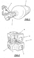
- connection system of a percussion head designated by the general reference 1, of an inflation cylinder designated by the general reference 2, has been illustrated with means forming a coil.
- inflatable safety equipment such as a liferaft (not shown).
- connection system comprises a connection designated by the general reference 3, which as can be seen more clearly on the figures 2 , 3 and 4 , comprises cylindrical fingerprints for receiving tubular connecting pieces of this percussion head and these inflatable tube means.
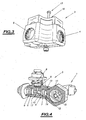
- the connector 3 has the general shape of a T which is thus provided with three indentations 4, 5 and 6, respectively adapted to receive respectively corresponding tips of the percussion head and means forming a coil. inflatable.
- Each endpiece such as, for example, endpiece 7 has a first peripheral groove, for example 10, for receiving an O-ring intended to constitute sealing means in the cavity between the corresponding end piece and the connection in order to avoid any leaks.
- Each endpiece is held in axial position in the corresponding recess of the connection by means of locking means comprising two locking tabs designated for example by references 11 and 12 for the recess 4 and the endpiece 7.
- These locking tabs are adapted to engage both in corresponding transverse grooves 13 and 14 of the coupling, formed on either side of the corresponding cavity, for example 4, thereof, and in a second peripheral groove for example 15, the tip 7, to ensure a locking in axial position of the corresponding tip in the cavity while allowing the case where appropriate, the rotation of the tip in the cavity.
- locking tabs associated with the different end pieces may have different lengths to allow successive assembly of the end pieces in the connection.
- this mounting plate designated by the general reference 16 on these figures 2 and 3 this plate being made for example of plastic and the tabs being integrally molded therewith.
- the corresponding transverse grooves of the coupling then have an open end opening on one side of the latter, which allows the locking tabs to be inserted into position in the latter by pushing the mounting plate thereof against the rest of the fitting.
- Means for fixing the plate to the rest of the connection may also be envisaged, these fixing means being for example formed by screw-nut means, as designated by the general reference 17 on the figure 3 , crossing the plate and the connection.
- connection system has a number of advantages over systems of the state of the art, especially in terms of its size and its reduced weight. It is also possible to use plastic material to make the different pieces entering the constitution of this system. This use of plastic material then makes it possible not to protect the connection vis-à-vis the environment.
- Such a system also does not require the use of specific mounting tools, such as a torque wrench or net brakes, while ensuring a very good seal due to the use of O-rings worn for example by the tips.
Landscapes
- Engineering & Computer Science (AREA)
- General Engineering & Computer Science (AREA)
- Mechanical Engineering (AREA)
- Ocean & Marine Engineering (AREA)
- Quick-Acting Or Multi-Walled Pipe Joints (AREA)
- Electric Ovens (AREA)
- Wrapping Of Specific Fragile Articles (AREA)
- Pressure Vessels And Lids Thereof (AREA)
- Emergency Lowering Means (AREA)
- Fertilizing (AREA)
- Catching Or Destruction (AREA)
- Feeding And Watering For Cattle Raising And Animal Husbandry (AREA)
- Telephone Set Structure (AREA)
- Percussive Tools And Related Accessories (AREA)
Claims (7)
- Anschlusseinrichtung für den Anschluss eines Schlagkopfs einer Aufpumpflasche an Mittel, die einen aufblasbaren Wulst einer Sicherheitseinrichtung bilden, welche ein Verbindungsstück (3), welches mit Eindrücken (4, 5, 6) zur Aufnahme von Ansatzstücken (7, 8, 9) zum Anschluss des Schlagkopfes (1) versehen ist, und einen aufblasbaren Wulst bildende Mittel und Mittel (11, 12, 13, 14, 15, 16, 17) zur Verriegelung der Ansatzstücke (7, 8, 9) in den entsprechenden Eindrücken (4, 5, 6) in axialer Lage aufweist, wobei die Verriegelungsmittel für jeden Eindruck wenigstens zwei. Verriegelungslappen (11, 12) aufweisen, die für einen Eingriff in entsprechende Querrinnen (13, 14), die im Verbindungsstück (3) auf beiden Seiten des entsprechenden Eindrucks (4) ausgenommen sind, eingerichtet sind und in diesen münden und auch in eine Randnut (15) des entsprechenden Ansatzstücks eingreifen, um diesen axial in dem entsprechenden Verbindungsstück zu blockieren, dadurch gekennzeichnet, dass die Verriegelungslappen (11, 12) von einer Montageplatte (16) am Verbindungsstück (3) getragen werden und dass die verschiedenen Eindrücken (4, 5, 6) zugeordneten Verriegelungslappen unterschiedlichen Längen aufweisen, um eine aufeinanderfolgende Montage der Ansatzstücke (7, 8, 9) in dem Verbindungsstück (3) zu gestatten.
- Anschlusseinrichtung nach Anspruch 1, dadurch gekennzeichnet, dass Dichtmittel zwischen dem Verbindungsstück und den Ansatzstücken vorgesehen sind.
- Anschlusseinrichtung nach Anspruch 2, dadurch gekennzeichnet, dass die Dichtmittel für jeden Ansatzstück (7, 8, 9) einen Dichtring aufweisen, der in einer Randnut (10) desselben aufgenommen ist.
- Anschlusseinrichtung nach einem der vorstehenden Ansprüche, dadurch gekennzeichnet, dass die Rinnen des Verbindungsstücks (3) ein offenes Ende aufweisen, das auf einer der Seiten des Verbindungsstücks (3) mündet, um so das Einführen der Verriegelungslappen zu gestatten.
- Anschlusseinrichtung nach einem der vorstehenden Ansprüche, dadurch gekennzeichnet, dass die Montageplatte (16) Befestigungsmittel (17) zur Befestigung am Verbindungsstück (3) aufweist.
- Anschlusseinrichtung nach Anspruch 5, dadurch gekennzeichnet, dass die Befestigungsmittel Mittel (17) zur Befestigung mit Schraube und Mutter aufweisen.
- Anschlusseinrichtung nach einem der vorstehenden Ansprüche, dadurch gekennzeichnet, dass sie aus Kunststoff hergestellt ist.
Applications Claiming Priority (2)
| Application Number | Priority Date | Filing Date | Title |
|---|---|---|---|
| FR0215933 | 2002-12-16 | ||
| FR0215933A FR2848637B1 (fr) | 2002-12-16 | 2002-12-16 | Systeme de raccordement d'une tete de percusion d'une bouteille de gonflage d'un equipement de securite |
Publications (2)
| Publication Number | Publication Date |
|---|---|
| EP1431647A1 EP1431647A1 (de) | 2004-06-23 |
| EP1431647B1 true EP1431647B1 (de) | 2008-05-21 |
Family
ID=32338841
Family Applications (1)
| Application Number | Title | Priority Date | Filing Date |
|---|---|---|---|
| EP03293098A Expired - Lifetime EP1431647B1 (de) | 2002-12-16 | 2003-12-10 | Anschlussanordnung eines zu einer Aufpumpflasche gehörenden Aufstechkopfes einer Sicherheitseinrichtung |
Country Status (5)
| Country | Link |
|---|---|
| EP (1) | EP1431647B1 (de) |
| AT (1) | ATE396359T1 (de) |
| DE (1) | DE60321118D1 (de) |
| DK (1) | DK1431647T3 (de) |
| FR (1) | FR2848637B1 (de) |
Family Cites Families (4)
| Publication number | Priority date | Publication date | Assignee | Title |
|---|---|---|---|---|
| DE1425470A1 (de) * | 1960-05-27 | 1968-11-21 | Daimler Benz Ag | Leicht loesbare Steckverbindung fuer Rohrleitungen od.dgl.,insbesondere in Kraftfahrzeugen |
| FR1468174A (fr) * | 1966-02-14 | 1967-02-03 | Gra Tec Inc | Structure de raccord pour éléments contenant du fluide |
| US4723929A (en) * | 1987-05-18 | 1988-02-09 | The B. F. Goodrich Company | Inflatable life rafts |
| DE4209000C1 (en) * | 1992-03-20 | 1993-05-27 | Mercedes-Benz Aktiengesellschaft, 7000 Stuttgart, De | Connector for fluid carrying pipes - has coaxial ring groove with sealing ring in each opening in the housing and has tensioning device with clamping lugs |
-
2002
- 2002-12-16 FR FR0215933A patent/FR2848637B1/fr not_active Expired - Fee Related
-
2003
- 2003-12-10 DK DK03293098T patent/DK1431647T3/da active
- 2003-12-10 DE DE60321118T patent/DE60321118D1/de not_active Expired - Lifetime
- 2003-12-10 EP EP03293098A patent/EP1431647B1/de not_active Expired - Lifetime
- 2003-12-10 AT AT03293098T patent/ATE396359T1/de not_active IP Right Cessation
Also Published As
| Publication number | Publication date |
|---|---|
| DK1431647T3 (da) | 2008-09-29 |
| EP1431647A1 (de) | 2004-06-23 |
| FR2848637A1 (fr) | 2004-06-18 |
| DE60321118D1 (de) | 2008-07-03 |
| ATE396359T1 (de) | 2008-06-15 |
| FR2848637B1 (fr) | 2005-10-07 |
Similar Documents
| Publication | Publication Date | Title |
|---|---|---|
| EP0340122B1 (de) | Schnellverbindungsvorrichtung für Verbindungselemente von Aufbauten, Gerüsten, Trägern und anderen Anordnungen | |
| FR2713305A1 (fr) | Dispositif de raccord rapide pour tubulures d'échangeur de chaleur. | |
| EP1481653A1 (de) | Ellenbogengelenkprothese | |
| FR2781548A1 (fr) | Raccord de tuyau avec un tuyau metallique elargi et procede de fabrication de celui-ci | |
| EP1241072A1 (de) | Verbindung eines Lenksäulenbügels mit einem Kraftfahrzeuglenkungsritzel | |
| FR2861673A1 (fr) | Dispositif de blocage en rotation a limitation de couple d'une colonne de direction de vehicule automobile | |
| EP1431647B1 (de) | Anschlussanordnung eines zu einer Aufpumpflasche gehörenden Aufstechkopfes einer Sicherheitseinrichtung | |
| EP2007957A1 (de) | Anordnung zur übertragung von bewegung zwischen insbesondere einer fahrzeugtürfalle und einem fahrzeugtürschloss | |
| FR2589979A1 (fr) | Dispositif de raccordement reutilisable pour tuyaux a ondes paralleles | |
| EP1378385B1 (de) | Endstück für die Aufrollvorrichtung von Wickelgut wie Planen oder Ähnlichem, speziell für Kraftfahrzeuge | |
| FR2581717A1 (fr) | Raccord pour l'assemblage angulaire d'organes tubulaires | |
| FR2799515A1 (fr) | Systeme a rattrapage de jeu pour fixer deux pieces l'une a l'autre au moyen d'un organe de fixation du type a vis | |
| WO2002021033A2 (fr) | Bague monobloc a compression liee principalement aux raccords de tuyauterie a compression de joint destines aux applications industrielles | |
| FR2641600A1 (fr) | Raccord d'extremite pour tuyaux | |
| FR2674491A1 (fr) | Dispositif de positionnement pour raccords de canalisations d'installations hydrauliques pour vehicules automobiles, notamment pour groupes de servodirection hydraulique. | |
| EP1104736B1 (de) | Vorrichtung zum Verbinden eines Lenkungsritzels mit einem Bügel | |
| FR2811699A1 (fr) | Charniere a couple controle | |
| FR2668240A1 (fr) | Dispositif de raccordement de deux tuyaux de part et d'autre d'un element de cloison. | |
| FR2763657A1 (fr) | Dispositif de fixation d'un element a un support mince | |
| FR3070136B1 (fr) | Outillage d'assemblage de deux conduits | |
| FR2705301A1 (fr) | Articulation de palonnier pour dispositif d'essuie-glace. | |
| FR2769427A1 (fr) | Systeme de fixation d'un boitier d'extremite sur une culasse d'un moteur electrique d'activation d'un organe fonctionnel de vehicule automobile | |
| FR2648524A1 (fr) | Dispositif de fixation du type ecrou-cage monobloc | |
| EP0508861A1 (de) | Kabeleinführung mit Verankerungsvorrichtung | |
| EP0881401B1 (de) | Schraubverbindung |
Legal Events
| Date | Code | Title | Description |
|---|---|---|---|
| PUAI | Public reference made under article 153(3) epc to a published international application that has entered the european phase |
Free format text: ORIGINAL CODE: 0009012 |
|
| AK | Designated contracting states |
Kind code of ref document: A1 Designated state(s): AT BE BG CH CY CZ DE DK EE ES FI FR GB GR HU IE IT LI LU MC NL PT RO SE SI SK TR |
|
| AX | Request for extension of the european patent |
Extension state: AL LT LV MK |
|
| 17P | Request for examination filed |
Effective date: 20041120 |
|
| AKX | Designation fees paid |
Designated state(s): AT BE BG CH CY CZ DE DK EE ES FI FR GB GR HU IE IT LI LU MC NL PT RO SE SI SK TR |
|
| 111Z | Information provided on other rights and legal means of execution |
Free format text: ATBEBGCHCYCZDEDKEEESFIFRGBGRHUIEITLUMCNLPTROSESISKTR Effective date: 20050323 |
|
| GRAP | Despatch of communication of intention to grant a patent |
Free format text: ORIGINAL CODE: EPIDOSNIGR1 |
|
| GRAS | Grant fee paid |
Free format text: ORIGINAL CODE: EPIDOSNIGR3 |
|
| GRAA | (expected) grant |
Free format text: ORIGINAL CODE: 0009210 |
|
| AK | Designated contracting states |
Kind code of ref document: B1 Designated state(s): AT BE BG CH CY CZ DE DK EE ES FI FR GB GR HU IE IT LI LU MC NL PT RO SE SI SK TR |
|
| REG | Reference to a national code |
Ref country code: GB Ref legal event code: FG4D Free format text: NOT ENGLISH |
|
| REG | Reference to a national code |
Ref country code: CH Ref legal event code: EP |
|
| REF | Corresponds to: |
Ref document number: 60321118 Country of ref document: DE Date of ref document: 20080703 Kind code of ref document: P |
|
| REG | Reference to a national code |
Ref country code: IE Ref legal event code: FG4D Free format text: LANGUAGE OF EP DOCUMENT: FRENCH |
|
| REG | Reference to a national code |
Ref country code: DK Ref legal event code: T3 |
|
| PG25 | Lapsed in a contracting state [announced via postgrant information from national office to epo] |
Ref country code: SI Free format text: LAPSE BECAUSE OF FAILURE TO SUBMIT A TRANSLATION OF THE DESCRIPTION OR TO PAY THE FEE WITHIN THE PRESCRIBED TIME-LIMIT Effective date: 20080521 |
|
| PG25 | Lapsed in a contracting state [announced via postgrant information from national office to epo] |
Ref country code: FI Free format text: LAPSE BECAUSE OF FAILURE TO SUBMIT A TRANSLATION OF THE DESCRIPTION OR TO PAY THE FEE WITHIN THE PRESCRIBED TIME-LIMIT Effective date: 20080521 Ref country code: ES Free format text: LAPSE BECAUSE OF FAILURE TO SUBMIT A TRANSLATION OF THE DESCRIPTION OR TO PAY THE FEE WITHIN THE PRESCRIBED TIME-LIMIT Effective date: 20080901 |
|
| NLV1 | Nl: lapsed or annulled due to failure to fulfill the requirements of art. 29p and 29m of the patents act | ||
| PG25 | Lapsed in a contracting state [announced via postgrant information from national office to epo] |
Ref country code: AT Free format text: LAPSE BECAUSE OF FAILURE TO SUBMIT A TRANSLATION OF THE DESCRIPTION OR TO PAY THE FEE WITHIN THE PRESCRIBED TIME-LIMIT Effective date: 20080521 Ref country code: NL Free format text: LAPSE BECAUSE OF FAILURE TO SUBMIT A TRANSLATION OF THE DESCRIPTION OR TO PAY THE FEE WITHIN THE PRESCRIBED TIME-LIMIT Effective date: 20080521 |
|
| REG | Reference to a national code |
Ref country code: IE Ref legal event code: FD4D |
|
| PG25 | Lapsed in a contracting state [announced via postgrant information from national office to epo] |
Ref country code: CZ Free format text: LAPSE BECAUSE OF FAILURE TO SUBMIT A TRANSLATION OF THE DESCRIPTION OR TO PAY THE FEE WITHIN THE PRESCRIBED TIME-LIMIT Effective date: 20080521 Ref country code: PT Free format text: LAPSE BECAUSE OF FAILURE TO SUBMIT A TRANSLATION OF THE DESCRIPTION OR TO PAY THE FEE WITHIN THE PRESCRIBED TIME-LIMIT Effective date: 20081021 Ref country code: SE Free format text: LAPSE BECAUSE OF FAILURE TO SUBMIT A TRANSLATION OF THE DESCRIPTION OR TO PAY THE FEE WITHIN THE PRESCRIBED TIME-LIMIT Effective date: 20080821 Ref country code: IE Free format text: LAPSE BECAUSE OF FAILURE TO SUBMIT A TRANSLATION OF THE DESCRIPTION OR TO PAY THE FEE WITHIN THE PRESCRIBED TIME-LIMIT Effective date: 20080521 |
|
| PG25 | Lapsed in a contracting state [announced via postgrant information from national office to epo] |
Ref country code: SK Free format text: LAPSE BECAUSE OF FAILURE TO SUBMIT A TRANSLATION OF THE DESCRIPTION OR TO PAY THE FEE WITHIN THE PRESCRIBED TIME-LIMIT Effective date: 20080521 Ref country code: RO Free format text: LAPSE BECAUSE OF FAILURE TO SUBMIT A TRANSLATION OF THE DESCRIPTION OR TO PAY THE FEE WITHIN THE PRESCRIBED TIME-LIMIT Effective date: 20080521 |
|
| PLBE | No opposition filed within time limit |
Free format text: ORIGINAL CODE: 0009261 |
|
| STAA | Information on the status of an ep patent application or granted ep patent |
Free format text: STATUS: NO OPPOSITION FILED WITHIN TIME LIMIT |
|
| 26N | No opposition filed |
Effective date: 20090224 |
|
| PG25 | Lapsed in a contracting state [announced via postgrant information from national office to epo] |
Ref country code: EE Free format text: LAPSE BECAUSE OF FAILURE TO SUBMIT A TRANSLATION OF THE DESCRIPTION OR TO PAY THE FEE WITHIN THE PRESCRIBED TIME-LIMIT Effective date: 20080521 Ref country code: BG Free format text: LAPSE BECAUSE OF FAILURE TO SUBMIT A TRANSLATION OF THE DESCRIPTION OR TO PAY THE FEE WITHIN THE PRESCRIBED TIME-LIMIT Effective date: 20080821 |
|
| PG25 | Lapsed in a contracting state [announced via postgrant information from national office to epo] |
Ref country code: MC Free format text: LAPSE BECAUSE OF NON-PAYMENT OF DUE FEES Effective date: 20081231 |
|
| PGFP | Annual fee paid to national office [announced via postgrant information from national office to epo] |
Ref country code: CH Payment date: 20091215 Year of fee payment: 7 Ref country code: DK Payment date: 20091123 Year of fee payment: 7 Ref country code: LU Payment date: 20091130 Year of fee payment: 7 |
|
| REG | Reference to a national code |
Ref country code: FR Ref legal event code: TP |
|
| PGFP | Annual fee paid to national office [announced via postgrant information from national office to epo] |
Ref country code: BE Payment date: 20100212 Year of fee payment: 7 |
|
| PG25 | Lapsed in a contracting state [announced via postgrant information from national office to epo] |
Ref country code: CY Free format text: LAPSE BECAUSE OF FAILURE TO SUBMIT A TRANSLATION OF THE DESCRIPTION OR TO PAY THE FEE WITHIN THE PRESCRIBED TIME-LIMIT Effective date: 20080521 Ref country code: HU Free format text: LAPSE BECAUSE OF FAILURE TO SUBMIT A TRANSLATION OF THE DESCRIPTION OR TO PAY THE FEE WITHIN THE PRESCRIBED TIME-LIMIT Effective date: 20081122 |
|
| PG25 | Lapsed in a contracting state [announced via postgrant information from national office to epo] |
Ref country code: TR Free format text: LAPSE BECAUSE OF FAILURE TO SUBMIT A TRANSLATION OF THE DESCRIPTION OR TO PAY THE FEE WITHIN THE PRESCRIBED TIME-LIMIT Effective date: 20080521 |
|
| REG | Reference to a national code |
Ref country code: CH Ref legal event code: PUE Owner name: PLASTIMO MARINE Free format text: PLASTIMO FRANCE#15, RUE INGENIEUR VERRIERE#56100 LORIENT (FR) -TRANSFER TO- PLASTIMO MARINE#15 RUE INGENIEUR VERRIERE#56100 LORIENT (FR) Ref country code: CH Ref legal event code: NV Representative=s name: BUGNION S.A. |
|
| REG | Reference to a national code |
Ref country code: GB Ref legal event code: 732E Free format text: REGISTERED BETWEEN 20100916 AND 20100922 |
|
| PG25 | Lapsed in a contracting state [announced via postgrant information from national office to epo] |
Ref country code: GR Free format text: LAPSE BECAUSE OF FAILURE TO SUBMIT A TRANSLATION OF THE DESCRIPTION OR TO PAY THE FEE WITHIN THE PRESCRIBED TIME-LIMIT Effective date: 20080822 |
|
| REG | Reference to a national code |
Ref country code: DE Ref legal event code: R081 Ref document number: 60321118 Country of ref document: DE Owner name: PLASTIMO MARINE, FR Free format text: FORMER OWNER: PLASTIMO FRANCE, LORIENT, FR Effective date: 20110214 |
|
| BERE | Be: lapsed |
Owner name: PLASTIMO FRANCE Effective date: 20101231 |
|
| REG | Reference to a national code |
Ref country code: CH Ref legal event code: PL |
|
| REG | Reference to a national code |
Ref country code: DK Ref legal event code: EBP |
|
| PG25 | Lapsed in a contracting state [announced via postgrant information from national office to epo] |
Ref country code: BE Free format text: LAPSE BECAUSE OF NON-PAYMENT OF DUE FEES Effective date: 20101231 |
|
| PG25 | Lapsed in a contracting state [announced via postgrant information from national office to epo] |
Ref country code: CH Free format text: LAPSE BECAUSE OF NON-PAYMENT OF DUE FEES Effective date: 20101231 Ref country code: LI Free format text: LAPSE BECAUSE OF NON-PAYMENT OF DUE FEES Effective date: 20101231 |
|
| PG25 | Lapsed in a contracting state [announced via postgrant information from national office to epo] |
Ref country code: LU Free format text: LAPSE BECAUSE OF NON-PAYMENT OF DUE FEES Effective date: 20101210 |
|
| REG | Reference to a national code |
Ref country code: FR Ref legal event code: PLFP Year of fee payment: 13 |
|
| REG | Reference to a national code |
Ref country code: FR Ref legal event code: PLFP Year of fee payment: 14 |
|
| REG | Reference to a national code |
Ref country code: FR Ref legal event code: PLFP Year of fee payment: 15 |
|
| REG | Reference to a national code |
Ref country code: FR Ref legal event code: PLFP Year of fee payment: 16 |
|
| PGFP | Annual fee paid to national office [announced via postgrant information from national office to epo] |
Ref country code: FR Payment date: 20200929 Year of fee payment: 18 |
|
| PGFP | Annual fee paid to national office [announced via postgrant information from national office to epo] |
Ref country code: DE Payment date: 20201209 Year of fee payment: 18 Ref country code: GB Payment date: 20201217 Year of fee payment: 18 Ref country code: IT Payment date: 20201210 Year of fee payment: 18 |
|
| REG | Reference to a national code |
Ref country code: DE Ref legal event code: R119 Ref document number: 60321118 Country of ref document: DE |
|
| GBPC | Gb: european patent ceased through non-payment of renewal fee |
Effective date: 20211210 |
|
| PG25 | Lapsed in a contracting state [announced via postgrant information from national office to epo] |
Ref country code: GB Free format text: LAPSE BECAUSE OF NON-PAYMENT OF DUE FEES Effective date: 20211210 Ref country code: DE Free format text: LAPSE BECAUSE OF NON-PAYMENT OF DUE FEES Effective date: 20220701 |
|
| PG25 | Lapsed in a contracting state [announced via postgrant information from national office to epo] |
Ref country code: FR Free format text: LAPSE BECAUSE OF NON-PAYMENT OF DUE FEES Effective date: 20211231 |
|
| PG25 | Lapsed in a contracting state [announced via postgrant information from national office to epo] |
Ref country code: IT Free format text: LAPSE BECAUSE OF NON-PAYMENT OF DUE FEES Effective date: 20211210 |