EP1431227A1 - Load detector of elevator - Google Patents
Load detector of elevator Download PDFInfo
- Publication number
- EP1431227A1 EP1431227A1 EP01945676A EP01945676A EP1431227A1 EP 1431227 A1 EP1431227 A1 EP 1431227A1 EP 01945676 A EP01945676 A EP 01945676A EP 01945676 A EP01945676 A EP 01945676A EP 1431227 A1 EP1431227 A1 EP 1431227A1
- Authority
- EP
- European Patent Office
- Prior art keywords
- detection
- pulley
- shackle
- frame
- detecting device
- Prior art date
- Legal status (The legal status is an assumption and is not a legal conclusion. Google has not performed a legal analysis and makes no representation as to the accuracy of the status listed.)
- Granted
Links
Images






Classifications
-
- B—PERFORMING OPERATIONS; TRANSPORTING
- B66—HOISTING; LIFTING; HAULING
- B66B—ELEVATORS; ESCALATORS OR MOVING WALKWAYS
- B66B3/00—Applications of devices for indicating or signalling operating conditions of elevators
-
- G—PHYSICS
- G01—MEASURING; TESTING
- G01G—WEIGHING
- G01G19/00—Weighing apparatus or methods adapted for special purposes not provided for in the preceding groups
- G01G19/14—Weighing apparatus or methods adapted for special purposes not provided for in the preceding groups for weighing suspended loads
-
- B—PERFORMING OPERATIONS; TRANSPORTING
- B66—HOISTING; LIFTING; HAULING
- B66B—ELEVATORS; ESCALATORS OR MOVING WALKWAYS
- B66B1/00—Control systems of elevators in general
- B66B1/34—Details, e.g. call counting devices, data transmission from car to control system, devices giving information to the control system
- B66B1/3476—Load weighing or car passenger counting devices
- B66B1/3484—Load weighing or car passenger counting devices using load cells
Definitions
- This invention relates to an elevator load detecting device for detecting a load on a car.
- Fig. 17 is a diagram showing the construction of an example of a conventional elevator load detecting device.
- a base 1 is provided with a plurality of through-holes 1a.
- a shackle rod 2 is passed through each through-hole 1a.
- Amain rope (not shown) is connected to the lower end portion of each shackle rod 2.
- a car and a balance weight are suspended in a hoistway by the main rope.
- a support plate 3 Fixed below the base 1 is a support plate 3 opposed to the lower surface of the base 1.
- the support plate 3 is provided with a plurality of through-holes 3a through which the shackle rods 2 are passed.
- a spring seat 4 is mounted to the upper end portion of each shackle rod 2. Further, threadedly engaged with the upper end portion of each shackle rod 2 is a nut 5 for regulating upward movement of the spring seat 4 with respect to the shackle rod 2.
- each shackle pipe 7 is fixed to the spring seat 4.
- a detection plate 8 is fixed to the lower end portions of the shackle pipes 7.
- the detection plate 8 is provided with a plurality of through-holes 8a through which the shackle rods 2 are passed.
- a differential transformer 9 Provided on the support plate 3 are a differential transformer 9 and a rotatable pulley 10.
- a wire 11 is connected between the detection plate 8 and the differential transformer 9. The intermediate portion of the wire 11 is wrapped around the pulley 10.
- the load of the car is supported by the base 1 through the main rope, the shackle rods 2, the nuts 5, the spring seats 4, and the shackle springs 6. Further, according to variations in the car load, the shackle rods 2 and the spring seats 4 are vertically displaced, and the shackle springs 6 expand and contract.
- the displacement amount of the spring seats 4 is transmitted to the detection plate 8 through the shackle pipes 7. Further, the detection plate 8 equalizes minute differences in displacement between the spring seats 4. Displacement of the detection plate 8 is transmitted to the differential transformer 9 through the wire 11. The differential transformer 9 outputs a signal according to the displacement amount of the detection plate 8. Thus, by computing the output signal from the differential transformer 9, it is possible to obtain the load on the car.
- a conventional load detecting device as described above is disclosed, for example, in JP 08-005605 B.
- the expansion/contraction amount of the shackle springs 6 is transmitted to the detection plate 8 through the spring seats 4 and the shackle pipes 7, and further, the displacement amount equalized by the detection plate 8 is transmitted to the differential transformer 9 through the wire 11, so that the transmission route is rather complicated, and there is the danger of an error being generated somewhere in the transmission route and the detection accuracy being deteriorated.
- This invention has been made with a view toward solving the above problem in the prior art. It is an object of this invention to provide an elevator load detecting device in which displacement of the shackle rods is transmitted through a simple transmission route and in which it is possible to achieve an improvement in accuracy in load detection.
- an elevator load detecting device which is provided in an elevator equipped with a car, a plurality of main ropes for suspending the car, a base for receiving a load applied to the main ropes, a plurality of shackle rods connected to end portions of the main ropes and adapted to be displaced with respect to the base according to the load, and a plurality of shackle springs provided between the shackle rods and the base and adapted to expand and contract with displacement of the shackle rods, the device adapted to detect the load of the car from displacement of the shackle rods, comprising: a pulley support member connected to at least one of the shackle rods and adapted to be displaced integrally with the shackle rods; a rotatable rod-side pulley mounted on the pulley support member; a frame provided on the base; a detection wire whose intermediate portion is wrapped around the rod-side pulley and whose
- Fig. 1 is a structural diagram showing an elevator according to Embodiment 1 of this invention.
- a base 12 is fixed in the upper portion of a hoistway 11.
- the base 12 consists, for example, of a support beam fixed to the upper portion of the interior of the hoistway 11 or the floor portion of a machine house.
- the base 12 supports a driving device 13.
- the driving device 13 has a drive sheave 14.
- a plurality of main ropes 15 are wrapped around the drive sheave 14. One end portion of each main rope 15 is connected to the base 12 through a first rope fastener portion 17a. The other end portion of each main rope 15 is connected to the base 12 through a second rope fastener portion 17b. A car 18 and a balance weight 19 are suspended in the hoistway 11 by the main ropes 15.
- the first rope fastener portion 17a is provided with a load detecting device 16.
- Fig. 2 is a front view showing the load detecting device 16 of Fig. 1
- Fig. 3 is a side view showing a main portion of Fig. 2.
- the main ropes 15 are respectively connected to the lower end portions of a plurality of shackle rods 21 passed through the base 12.
- a spring seat 22 is mounted to the upper end portion of each shackle rod 21. Threadedly engaged with the upper end portion of each shackle rod 21 are a plurality of nuts 23 for regulating upward movement of the spring seat 22 with respect to the shackle rod 21.
- a plurality of shackle springs (coil springs) 24 receiving the load of the shackle rods 21 are arranged so as to surround the shackle rods 21.
- the first rope fastener portion 17a has the shackle rods 21, the spring seats 22, the nuts 23, and the shackle springs 24.
- a pulley support member 25 adapted to be displaced with the shackle rod 21 is mounted to the upper end portion of each shackle rod 21 by means of a plurality of nuts 26.
- a rotatable rod-side pulley 27 is mounted on each pulley support member 25.
- a frame 28 is provided upright on the base 12.
- a plurality of rotatable frame-side pulleys 29 are mounted on the frame 28.
- the intermediate portion of a detection wire 30 is alternately wrapped around the rod-side pulleys 27 and the frame-side pulleys 29.
- One end portion of the detection wire 30 is fastened to the frame 28 through the intermediation of a fastening member 31 having a bar screw 31a and a plurality of nuts 31b.
- the detector 32 for detecting the displacement amount of the shackle rods 21 (the expansion/contraction amount of the shackle springs 24) through the detection wire 30.
- the detector 32 has a detection shaft 33 fixed to the frame 28, a detection pulley 34 around which the other end portion of the detection wire 30 is fixedly wrapped and which is rotatable about the detection shaft 33, a torsion spring 35 as tension imparting means which urges the detection pulley 34 so as to take up the detection wire 30 (counterclockwise in Fig. 2) and which imparts tension to the detection wire 30, and an angle sensor 36 which detects the rotation angle of the detection pulley 34 and outputs a detection signal.
- the angle sensor 36 has a sensor substrate 36a mounted on the detection pulley 34, a sensor main body 36b mounted on the sensor substrate, and a connector (not shown).
- a sensor main body 36b As the sensor main body 36b, an inclination sensor, for example, is used whose output varies according to the angle (inclination) of the sensor main body 36b.
- the rotation angle of the detection pulley 34 varies according to the load of the car 18. Further, the rotation angle of the detection pulley 34 is detected by the sensor main body 36. Thus, a detection signal in proportion to the load of the car 18 is output from the sensor main body 36. By computing the output signal from the sensor main body 36, it is possible to obtain the load of the car 18.
- the variation amount of the length between one end portion of the detection wire 30 and the detection pulley 34 is double the total displacement amount of the three shackle rods 21, so that it is possible to perform detection with displacement amount enlarged, whereby it is possible to achieve an improvement in detection accuracy with a simple structure.
- the diameter of the pulley 34 it is possible to adjust the variation amount of the rotation angle of the detection pulley 34 with respect to the variation amount of the detection wire 30, thereby being capable of achieving an improvement in detection accuracy. Further, it is possible to facilitate the setting of the resolution and detection angle. That is, taking into account the output characteristics of the sensor main body 36b, it is possible to select the diameter of the pulley 34 such that the angle of the sensor main body 36b varies within a range which allows detection with optimum accuracy.
- the detection wire 30 is fastened to the frame 2 8 through the intermediation of the fastening member 31 having the bar screw 31a and the plurality of nuts 31b, the detection wire 30 is moved by displacing the bar screw 31a with respect to the frame 28, making it possible to easily reset the angle of the detection pulley 34.
- Fig. 4 is a structural diagram showing an elevator according to Embodiment 2 of this invention.
- a driving device 41 is arranged in the upper portion of the hoistway 11.
- the driving device 41 is provided with a drive sheave 42 and a deflector wheel 43.
- a plurality of main ropes 44 are wrapped around the drive sheave 42 and the deflector wheel 43.
- a car 45 is suspended at one end of the main ropes 44.
- a balance weight 46 is suspended.
- One end portions of the main ropes 44 are connected to the car 45 through the intermediation of a first rope fastener portion 47a.
- the other end portions of the main ropes 44 are connected to the balance weight 46 through the intermediation of a second rope fastener portion 47b.
- the first rope fastener portion 47a is provided with a load detecting device 16.
- the construction of the load detecting device 16 is the same as that of Embodiment 1; it is used upside down as compared to the case of Figs. 2 and 3. Further, in Embodiment 2, the base 12 is an upper beam situated, for example, in the upper portion of the car 45.
- Embodiment 1 is applied to a 2:1 roping type elevator
- this invention is also applicable to a 1:1 roping type elevator by mounting the load detecting device 16 on the car 45 as shown in Fig. 4, making it possible to obtain the same effect as that of Embodiment 1.
- Fig. 5 is a front view showing an elevator load detecting device according to Embodiment 3 of this invention
- Fig. 6 is a front view of the detection pulley of Fig. 5
- Fig. 7 is a bottom view showing the detection pulley of Fig. 6.
- mounted on the frame 28 is a detector 51 for detecting the displacement amount of the shackle rods 21 through the detection wire 30.
- the detector 51 has a detection shaft 33 fixed to the frame 28, a detection pulley 52 around which the other end portion of the detection wire 30 is fixedly wrapped and which is rotatable about the detection shaft 33, a tension imparting means 53 which urges the detection pulley 52 so as to take up the detection wire 30 (counterclockwise in Fig. 5) and imparts tension to the detection wire 30, and a sensor main body 36 which detects the rotation angle of the detection pulley 52 and outputs a detection signal.
- the tension imparting means 53 has a tension imparting wire 54 whose one end portion is fixedly wrapped around the detection pulley 52, and a tension spring 55 connected between the tension imparting wire 54 and the frame 28.
- first and second grooves 52a and 52b In the outer peripheral portion of the detection pulley 52, there are provided first and second grooves 52a and 52b.
- the detection wire 30 is wrapped around the first groove 52a, and the tension imparting wire 54 is wrapped around the second groove 52b.
- this embodiment is of the same construction as Embodiment 1.
- the tension imparting means 53 having the tension imparting wire 54 and the tension spring 55 is used, so that even if the diameter of the detection pulley 52 is changed, the tension imparted to the detection wire 30 is the same as the resilient force of the tension spring 55, making it possible to impart tension to the detection wire 30 in a stable manner and to freely select the diameter of the detection pulley 52.
- the detection wire 30 and the tension imparting wire 54 are fixed to the detection pulley 52, it is possible to prevent occurrence of slippage between the wires 30, 54 and the detection pulley 52.
- wires 30 and 54 are separately wrapped around the first and second grooves 52a and 52b, so that even when the rotation angle of the detection pulley 52 is large, it is possible to smoothly take up the wires without involving intersection.
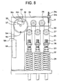
- Fig. 8 is a front view showing an elevator load detecting device according to Embodiment 4 of this invention.
- mounted on the frame 28 is a detector 57 for detecting the displacement amount of the shackle rods 21 through the detection wire 30.
- the detector 57 has a detection shaft 33 fixed to the frame 28, a detection pulley 52 around which the other end portion of the detection wire 30 is fixedly wrapped and which is rotatable about the detection shaft 33, a tension imparting means 58 which urges the detection pulley 52 so as to take up the detection wire (counterclockwise in Fig. 8) and imparts tension to the detection wire 30, and a sensor main body 36 which detects the rotation angle of the detection pulley 52 and outputs a detection signal.
- the tension imparting means 58 has a tension imparting wire 54 whose one end portion is fixedly wrapped around the detection pulley 52 and a weight 59 suspended at the other end of the tension imparting wire 54. Otherwise, this embodiment is of the same construction as Embodiment 3.
- the tension imparted to the detection wire 30 is determined by the weight of the weight 59, so that the tension is kept at a fixed level, and the expansion of the detection wire 30 is fixed. Thus, it is possible to achieve an improvement in detection accuracy.
- Fig. 9 is a front view showing an elevator load detecting device according to Embodiment 5 of this invention.
- an indicator 61 is fixed to the outer peripheral portion of the detection pulley 34. Further, on the frame 28, there is provided a scale 62 opposed to the indicator 61. Otherwise, this embodiment is of the same construction as Embodiment 1.
- the state in which half the rated load (half load) is on the car 18 is the reference state; by effecting adjustment such that the indicator 61 indicates zero of the scale 62 in the reference state, the indicator 61 moves to the right from zero when the load is less than that of the reference state. When the load is larger than that of the reference state, the indicator 61 moves to the left from zero.
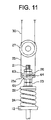
- Fig. 10 is a side view showing a main portion of an elevator load detecting device according to Embodiment 6 of this invention
- Fig. 11 is a front view showing a main portion of Fig. 10.
- a pulley support member 25 has a horizontal portion 25a through which a shackle rod 21 is passed.
- a support seat 63 mounted to the shackle rod 21 is a support seat 63 opposed to the upper surface of the horizontal portion 25a. Upward movement of the support seat 63 is regulated by a nut 26.
- Fig. 12 is a sectional view of the nut 26 and the support seat 63 of Fig. 11, and Fig. 13 is a bottom view showing the support seat 63 of Fig. 12.
- annular support groove 63a with a V-shaped sectional structure whose center is at the center of the cross section of the shackle rod 21.
- the pair of protrusions 64 are arranged such that they are positioned in a straight line passing the center of the cross section of the shackle rod 21. Further, the forward end portions of the protrusions 64 are inserted into the support groove 63a and abut the inner wall of the support groove 63a. Otherwise, this embodiment is of the same construction of Embodiment 1.
- the support seat 63 and the protrusions 64 are provided between the pulley support member 25 and the shackle rod 21, and the protrusions 64 are held in point contact with the support seat 63, so that relative inclination of the shackle rod 21 with respect to the horizontal portion 25a is permitted.
- FIG. 14 is a side view showing a state in which the shackle rod 21 of Fig. 10 is inclined, with the shackle rod 21 being inclined about the rocking center C.
- the elastic member 65 exists between the horizontal portion 25a and the shackle spring 24, the protrusions 64 are not separated from the support seat 63 even when the shackle rod 21 moves violently, making it possible to swing the pulley support member 25 in a stable manner with respect to the shackle rod 21. Further, it is possible to restrain generation of noise in the contact portion.
- Fig. 15 is a side view showing a main portion of an elevator load detecting device according to Embodiment 7 of this invention
- Fig. 16 is a half sectional view of a main portion of Fig. 15.
- the collar 71 is passed through the horizontal portion 25a of the pulley support member 25.
- An elastic member 65 exists between the horizontal portion 25a and the spring seat 22.
- Above the horizontal portion 25a there is arranged an annular support seat (guide member) 72 surrounding the collar 71.
- annular support groove 72a In the lower surface of the support seat 72, there is provided an annular support groove 72a opposed to the horizontal portion 25a.
- the support groove 72a has a V-shaped sectional structure.
- a pair of semi-spherical protrusions 64 are fixed to the horizontal portion 25a.
- the pair of protrusions 64 are arranged so as to be situated in a straight line passing the center of the cross section of the shackle rod 21.
- the forward end portions of the protrusions 64 are inserted into the support groove 72a, and abut the inner wall of the support groove 72a.
- Attached to the outer peripheral portion of the collar 71 is a retaining ring (e.g., an E-ring) 73 for regulating upward movement of the support seat 72.
- the pulley support member 25 can be mounted at a position in the vicinity of the shackle spring 24, making it possible to restrain the error due to inclination of the shackle rod 21 and to achieve an improvement in detection accuracy.
- the nut 23 can be spaced apart from the spring seat 22 without deteriorating the detection accuracy.
- the distance between the adjacent shackle rods 21 is small, when the nuts 23 are threadedly engaged with the adjacent rods 21 at the same height, a sufficient space cannot be secured, and it is difficult to fasten the nuts 23.
- the fastening of the nut 23 can be facilitated.
- the detectors 32, 51, and 57 for detecting the rotation angle of the detection pulleys 34 and 52 are used, it is also possible to use, for example, a differential transformer as long as it is possible to detect the displacement amount of the shackle rod 21 from the displacement amount of the other end portion of the detection wire 30.
- the pulley support members 25 and the rod-side pulleys 27 are mounted to all of the three shackle rods 21, it is also possible to mount the pulley support members 25 and the rod-side pulleys only to a part of a plurality of shackle rods.
- the pulley support member and the rod-side pulley are mounted to only one of a plurality of shackle rods.
- the frame-side pulley is unnecessary; however, by wrapping the detection wire around the rod-side pulley, it is possible to detect the displacement of the shackle rod in an enlarged state.
- N-1) frame-side pulleys are preferably used for N rod-side pulleys (N is an integer of 2 or more), with the detection wire being alternately wrapped.
Landscapes
- Engineering & Computer Science (AREA)
- Mechanical Engineering (AREA)
- Automation & Control Theory (AREA)
- Physics & Mathematics (AREA)
- General Physics & Mathematics (AREA)
- Computer Networks & Wireless Communication (AREA)
- Maintenance And Inspection Apparatuses For Elevators (AREA)
- Lift-Guide Devices, And Elevator Ropes And Cables (AREA)
- Indicating And Signalling Devices For Elevators (AREA)
Abstract
Description
- This invention relates to an elevator load detecting device for detecting a load on a car.
- Fig. 17 is a diagram showing the construction of an example of a conventional elevator load detecting device. In the drawing, a base 1 is provided with a plurality of through-holes 1a. A shackle rod 2 is passed through each through-hole 1a. Amain rope (not shown) is connected to the lower end portion of each shackle rod 2. A car and a balance weight are suspended in a hoistway by the main rope.
- Fixed below the base 1 is a
support plate 3 opposed to the lower surface of the base 1. Thesupport plate 3 is provided with a plurality of through-holes 3a through which the shackle rods 2 are passed. A spring seat 4 is mounted to the upper end portion of each shackle rod 2. Further, threadedly engaged with the upper end portion of each shackle rod 2 is a nut 5 for regulating upward movement of the spring seat 4 with respect to the shackle rod 2. - Between the base 1 and the spring seats 4, there are arranged a plurality of shackle springs (coil springs) 6 receiving the load of the shackle rods 2 so as to surround the shackle rods 2. Passed through the through-holes 1a of the base 1 are a plurality of shackle pipes 7 surrounding the shackle rods 2. The upper end portion of each shackle pipe 7 is fixed to the spring seat 4.
- A
detection plate 8 is fixed to the lower end portions of the shackle pipes 7. Thedetection plate 8 is provided with a plurality of through-holes 8a through which the shackle rods 2 are passed. Provided on thesupport plate 3 are a differential transformer 9 and a rotatable pulley 10. Awire 11 is connected between thedetection plate 8 and the differential transformer 9. The intermediate portion of thewire 11 is wrapped around the pulley 10. - Next, the operation of this device will be described. The load of the car is supported by the base 1 through the main rope, the shackle rods 2, the nuts 5, the spring seats 4, and the shackle springs 6. Further, according to variations in the car load, the shackle rods 2 and the spring seats 4 are vertically displaced, and the shackle springs 6 expand and contract.
- The displacement amount of the spring seats 4 is transmitted to the
detection plate 8 through the shackle pipes 7. Further, thedetection plate 8 equalizes minute differences in displacement between the spring seats 4. Displacement of thedetection plate 8 is transmitted to the differential transformer 9 through thewire 11. The differential transformer 9 outputs a signal according to the displacement amount of thedetection plate 8. Thus, by computing the output signal from the differential transformer 9, it is possible to obtain the load on the car. - A conventional load detecting device as described above is disclosed, for example, in JP 08-005605 B.
- In the above-described conventional construction, the expansion/contraction amount of the shackle springs 6 is transmitted to the
detection plate 8 through the spring seats 4 and the shackle pipes 7, and further, the displacement amount equalized by thedetection plate 8 is transmitted to the differential transformer 9 through thewire 11, so that the transmission route is rather complicated, and there is the danger of an error being generated somewhere in the transmission route and the detection accuracy being deteriorated. - This invention has been made with a view toward solving the above problem in the prior art. It is an object of this invention to provide an elevator load detecting device in which displacement of the shackle rods is transmitted through a simple transmission route and in which it is possible to achieve an improvement in accuracy in load detection.
- To this end, according to one aspect of the present invention, there is provided an elevator load detecting device which is provided in an elevator equipped with a car, a plurality of main ropes for suspending the car, a base for receiving a load applied to the main ropes, a plurality of shackle rods connected to end portions of the main ropes and adapted to be displaced with respect to the base according to the load, and a plurality of shackle springs provided between the shackle rods and the base and adapted to expand and contract with displacement of the shackle rods, the device adapted to detect the load of the car from displacement of the shackle rods, comprising: a pulley support member connected to at least one of the shackle rods and adapted to be displaced integrally with the shackle rods; a rotatable rod-side pulley mounted on the pulley support member; a frame provided on the base; a detection wire whose intermediate portion is wrapped around the rod-side pulley and whose one end portion is connected to the frame; and a detector which is mounted on the frame, to which the other end portion of the detection wire is connected and which is adapted to detect the displacement amount of the shackle rods through the detection wire.
-
- Fig. 1 is a structural diagram showing an elevator according to Embodiment 1 of this invention;
- Fig. 2 is a front view showing a load detecting device of Fig. 1;
- Fig. 3 is a side view showing a main portion of Fig. 2;
- Fig. 4 is a structural diagram showing an elevator according to Embodiment 2 of this invention;
- Fig. 5 is a front view showing an elevator load detecting device
according to
Embodiment 3 of this invention; - Fig. 6 is a front view showing a detection pulley of Fig. 5;
- Fig. 7 is a bottom view showing the detection pulley of Fig. 6;
- Fig. 8 is a front view showing an elevator load detecting device according to Embodiment 4 of this invention;
- Fig. 9 is a front view showing an elevator load detecting device according to Embodiment 5 of this invention;
- Fig. 10 is a side view showing a main portion of an elevator load detecting device according to Embodiment 6 of this invention;
- Fig. 11 is a front view showing a main portion of Fig. 10;
- Fig. 12 is a sectional view of a nut and support seat of Fig. 11;
- Fig. 13 is a bottom view of the support seat of Fig. 12;
- Fig. 14 is a side view showing a state in which a shackle rod of Fig. 10 is inclined;
- Fig. 15 is a side view showing a main portion of an elevator load detecting device according to Embodiment 7 of this invention;
- Fig. 16 is a half sectional view of a main portion of Fig. 15; and
- Fig. 17 is a structural diagram showing an example of a conventional elevator load detecting device.
-
- Preferred embodiments of this invention will now be described with reference to the drawings.
- Fig. 1 is a structural diagram showing an elevator according to Embodiment 1 of this invention. In the drawing, a
base 12 is fixed in the upper portion of ahoistway 11. Thebase 12 consists, for example, of a support beam fixed to the upper portion of the interior of thehoistway 11 or the floor portion of a machine house. Thebase 12 supports adriving device 13. Thedriving device 13 has a drive sheave 14. - A plurality of
main ropes 15 are wrapped around the drive sheave 14. One end portion of eachmain rope 15 is connected to thebase 12 through a first rope fastener portion 17a. The other end portion of eachmain rope 15 is connected to thebase 12 through a secondrope fastener portion 17b. Acar 18 and abalance weight 19 are suspended in thehoistway 11 by themain ropes 15. The first rope fastener portion 17a is provided with aload detecting device 16. - Next, Fig. 2 is a front view showing the
load detecting device 16 of Fig. 1, and Fig. 3 is a side view showing a main portion of Fig. 2. In the drawings, themain ropes 15 are respectively connected to the lower end portions of a plurality ofshackle rods 21 passed through thebase 12. Aspring seat 22 is mounted to the upper end portion of eachshackle rod 21. Threadedly engaged with the upper end portion of eachshackle rod 21 are a plurality ofnuts 23 for regulating upward movement of thespring seat 22 with respect to theshackle rod 21. - Between the
base 12 and the spring seats 22, a plurality of shackle springs (coil springs) 24 receiving the load of theshackle rods 21 are arranged so as to surround theshackle rods 21. The first rope fastener portion 17a has theshackle rods 21, the spring seats 22, the nuts 23, and the shackle springs 24. - A
pulley support member 25 adapted to be displaced with theshackle rod 21 is mounted to the upper end portion of eachshackle rod 21 by means of a plurality of nuts 26. A rotatable rod-side pulley 27 is mounted on eachpulley support member 25. - A
frame 28 is provided upright on thebase 12. A plurality of rotatable frame-side pulleys 29 are mounted on theframe 28. The intermediate portion of adetection wire 30 is alternately wrapped around the rod-side pulleys 27 and the frame-side pulleys 29. One end portion of thedetection wire 30 is fastened to theframe 28 through the intermediation of afastening member 31 having abar screw 31a and a plurality of nuts 31b. - Mounted on the
frame 28 is adetector 32 for detecting the displacement amount of the shackle rods 21 (the expansion/contraction amount of the shackle springs 24) through thedetection wire 30. Thedetector 32 has adetection shaft 33 fixed to theframe 28, adetection pulley 34 around which the other end portion of thedetection wire 30 is fixedly wrapped and which is rotatable about thedetection shaft 33, atorsion spring 35 as tension imparting means which urges thedetection pulley 34 so as to take up the detection wire 30 (counterclockwise in Fig. 2) and which imparts tension to thedetection wire 30, and anangle sensor 36 which detects the rotation angle of thedetection pulley 34 and outputs a detection signal. - The
angle sensor 36 has asensor substrate 36a mounted on thedetection pulley 34, a sensormain body 36b mounted on the sensor substrate, and a connector (not shown). As the sensormain body 36b, an inclination sensor, for example, is used whose output varies according to the angle (inclination) of the sensormain body 36b. - Next, the operation of this device will be described. When the load of the
car 18 varies, theshackle rods 21 are vertically displaced, and the shackle springs 24 are expanded/contracted. Further, when theshackle rods 21 are displaced, thepulley support members 25 and the rod-side pulleys 27 are also integrally displaced, and the length between one end portion of thedetection wire 30 and thedetection pulley 34 varies, with the result that the rotation angle of thedetection pulley 34 varies. - That is, the rotation angle of the
detection pulley 34 varies according to the load of thecar 18. Further, the rotation angle of thedetection pulley 34 is detected by the sensormain body 36. Thus, a detection signal in proportion to the load of thecar 18 is output from the sensormain body 36. By computing the output signal from the sensormain body 36, it is possible to obtain the load of thecar 18. - In this
load detecting device 16, the variation amount of the length between one end portion of thedetection wire 30 and thedetection pulley 34 is double the total displacement amount of the threeshackle rods 21, so that it is possible to perform detection with displacement amount enlarged, whereby it is possible to achieve an improvement in detection accuracy with a simple structure. - Further, by appropriately selecting the diameter of the
pulley 34, it is possible to adjust the variation amount of the rotation angle of thedetection pulley 34 with respect to the variation amount of thedetection wire 30, thereby being capable of achieving an improvement in detection accuracy. Further, it is possible to facilitate the setting of the resolution and detection angle. That is, taking into account the output characteristics of the sensormain body 36b, it is possible to select the diameter of thepulley 34 such that the angle of the sensormain body 36b varies within a range which allows detection with optimum accuracy. - Further, a change in the number of
main ropes 15 can be easily coped with. - Furthermore, since one end portion of the
detection wire 30 is fastened to the frame 2 8 through the intermediation of thefastening member 31 having thebar screw 31a and the plurality of nuts 31b, thedetection wire 30 is moved by displacing thebar screw 31a with respect to theframe 28, making it possible to easily reset the angle of thedetection pulley 34. - Next, Fig. 4 is a structural diagram showing an elevator according to Embodiment 2 of this invention. In the drawing, a driving device 41 is arranged in the upper portion of the
hoistway 11. The driving device 41 is provided with adrive sheave 42 and adeflector wheel 43. A plurality ofmain ropes 44 are wrapped around thedrive sheave 42 and thedeflector wheel 43. Acar 45 is suspended at one end of themain ropes 44. At the other end of themain ropes 44, abalance weight 46 is suspended. - One end portions of the
main ropes 44 are connected to thecar 45 through the intermediation of a first rope fastener portion 47a. The other end portions of themain ropes 44 are connected to thebalance weight 46 through the intermediation of a secondrope fastener portion 47b. - The first rope fastener portion 47a is provided with a
load detecting device 16. The construction of theload detecting device 16 is the same as that of Embodiment 1; it is used upside down as compared to the case of Figs. 2 and 3. Further, in Embodiment 2, thebase 12 is an upper beam situated, for example, in the upper portion of thecar 45. - While Embodiment 1 is applied to a 2:1 roping type elevator, this invention is also applicable to a 1:1 roping type elevator by mounting the
load detecting device 16 on thecar 45 as shown in Fig. 4, making it possible to obtain the same effect as that of Embodiment 1. - Next, Fig. 5 is a front view showing an elevator load detecting device according to
Embodiment 3 of this invention, Fig. 6 is a front view of the detection pulley of Fig. 5, and Fig. 7 is a bottom view showing the detection pulley of Fig. 6. In the drawings, mounted on theframe 28 is adetector 51 for detecting the displacement amount of theshackle rods 21 through thedetection wire 30. - The
detector 51 has adetection shaft 33 fixed to theframe 28, adetection pulley 52 around which the other end portion of thedetection wire 30 is fixedly wrapped and which is rotatable about thedetection shaft 33, a tension imparting means 53 which urges thedetection pulley 52 so as to take up the detection wire 30 (counterclockwise in Fig. 5) and imparts tension to thedetection wire 30, and a sensormain body 36 which detects the rotation angle of thedetection pulley 52 and outputs a detection signal. - The tension imparting means 53 has a
tension imparting wire 54 whose one end portion is fixedly wrapped around thedetection pulley 52, and atension spring 55 connected between thetension imparting wire 54 and theframe 28. - In the outer peripheral portion of the
detection pulley 52, there are provided first andsecond grooves detection wire 30 is wrapped around thefirst groove 52a, and thetension imparting wire 54 is wrapped around thesecond groove 52b. - Further, in the outer peripheral portion of the
detection pulley 52, there is provided aslit 52c. Ametal fixing member 56 is inserted into theslit 52c. The other end portion of thedetection wire 30 and one end portion of thetension imparting wire 54 are held between theslit 52c and themetal fixing member 56 and fixed to thedetection pulley 52. Otherwise, this embodiment is of the same construction as Embodiment 1. - In this load detecting device, the tension imparting means 53 having the
tension imparting wire 54 and thetension spring 55 is used, so that even if the diameter of thedetection pulley 52 is changed, the tension imparted to thedetection wire 30 is the same as the resilient force of thetension spring 55, making it possible to impart tension to thedetection wire 30 in a stable manner and to freely select the diameter of thedetection pulley 52. - Further, since the
detection wire 30 and thetension imparting wire 54 are fixed to thedetection pulley 52, it is possible to prevent occurrence of slippage between thewires detection pulley 52. - Further, the
wires second grooves detection pulley 52 is large, it is possible to smoothly take up the wires without involving intersection. - While in
Embodiment 3, thewires detection pulley 52, it is also possible to separately fix them at different position. - Next, Fig. 8 is a front view showing an elevator load detecting device according to Embodiment 4 of this invention. In the drawing, mounted on the
frame 28 is adetector 57 for detecting the displacement amount of theshackle rods 21 through thedetection wire 30. - The
detector 57 has adetection shaft 33 fixed to theframe 28, adetection pulley 52 around which the other end portion of thedetection wire 30 is fixedly wrapped and which is rotatable about thedetection shaft 33, a tension imparting means 58 which urges thedetection pulley 52 so as to take up the detection wire (counterclockwise in Fig. 8) and imparts tension to thedetection wire 30, and a sensormain body 36 which detects the rotation angle of thedetection pulley 52 and outputs a detection signal. - The tension imparting means 58 has a
tension imparting wire 54 whose one end portion is fixedly wrapped around thedetection pulley 52 and aweight 59 suspended at the other end of thetension imparting wire 54. Otherwise, this embodiment is of the same construction asEmbodiment 3. - In this load detecting device, the tension imparted to the
detection wire 30 is determined by the weight of theweight 59, so that the tension is kept at a fixed level, and the expansion of thedetection wire 30 is fixed. Thus, it is possible to achieve an improvement in detection accuracy. - Next, Fig. 9 is a front view showing an elevator load detecting device according to Embodiment 5 of this invention. In the drawing, an
indicator 61 is fixed to the outer peripheral portion of thedetection pulley 34. Further, on theframe 28, there is provided ascale 62 opposed to theindicator 61. Otherwise, this embodiment is of the same construction as Embodiment 1. - In this load detecting device, it is possible to effect the angle adjustment of the
detection pulley 34 more accurately and to reset the angle of thedetection pulley 34 more easily. - Suppose, for example, the state in which half the rated load (half load) is on the
car 18 is the reference state; by effecting adjustment such that theindicator 61 indicates zero of thescale 62 in the reference state, theindicator 61 moves to the right from zero when the load is less than that of the reference state. When the load is larger than that of the reference state, theindicator 61 moves to the left from zero. - Next, Fig. 10 is a side view showing a main portion of an elevator load detecting device according to Embodiment 6 of this invention, and Fig. 11 is a front view showing a main portion of Fig. 10. In the drawings, a
pulley support member 25 has ahorizontal portion 25a through which ashackle rod 21 is passed. Mounted to theshackle rod 21 is asupport seat 63 opposed to the upper surface of thehorizontal portion 25a. Upward movement of thesupport seat 63 is regulated by anut 26. - Fixed to the
horizontal portion 25a are a pair ofsemi-spherical protrusions 64 held in point contact with thee supportseat 63. Between thehorizontal portion 25a and thenut 23, there is provided anelastic member 65 consisting of rubber or the like through which theshackle rod 21 is passed. - Fig. 12 is a sectional view of the
nut 26 and thesupport seat 63 of Fig. 11, and Fig. 13 is a bottom view showing thesupport seat 63 of Fig. 12. In the drawings, in the bottom surface of thesupport seat 63, there is provided anannular support groove 63a with a V-shaped sectional structure whose center is at the center of the cross section of theshackle rod 21. - The pair of
protrusions 64 are arranged such that they are positioned in a straight line passing the center of the cross section of theshackle rod 21. Further, the forward end portions of theprotrusions 64 are inserted into thesupport groove 63a and abut the inner wall of thesupport groove 63a. Otherwise, this embodiment is of the same construction of Embodiment 1. - In this load detecting device, the
support seat 63 and theprotrusions 64 are provided between thepulley support member 25 and theshackle rod 21, and theprotrusions 64 are held in point contact with thesupport seat 63, so that relative inclination of theshackle rod 21 with respect to thehorizontal portion 25a is permitted. - That is, even if the
shackle rod 21 is inclined as a result of ascent/descent of thecar 18, the rod-side pulley 27 is always pulled in the same direction by the tension acting on thedetection wire 30, so that the rod-side pulley 27 is not inclined. Thus, it is possible to prevent generation of detection error due to inclination of theshackle rod 21. Fig. 14 is a side view showing a state in which theshackle rod 21 of Fig. 10 is inclined, with theshackle rod 21 being inclined about the rocking center C. - Further, since the
elastic member 65 exists between thehorizontal portion 25a and theshackle spring 24, theprotrusions 64 are not separated from thesupport seat 63 even when theshackle rod 21 moves violently, making it possible to swing thepulley support member 25 in a stable manner with respect to theshackle rod 21. Further, it is possible to restrain generation of noise in the contact portion. - Next, Fig. 15 is a side view showing a main portion of an elevator load detecting device according to Embodiment 7 of this invention, and Fig. 16 is a half sectional view of a main portion of Fig. 15.
- In the drawings, between the
nut 23 and thespring seat 22, there is arranged acylindrical collar 71 surrounding theshackle rod 21. The load of theshackle rod 21 is transmitted to theshackle spring 24 through thenut 23, thecollar 71, and thespring seat 22. - The
collar 71 is passed through thehorizontal portion 25a of thepulley support member 25. Anelastic member 65 exists between thehorizontal portion 25a and thespring seat 22. Above thehorizontal portion 25a, there is arranged an annular support seat (guide member) 72 surrounding thecollar 71. In the lower surface of thesupport seat 72, there is provided an annular support groove 72a opposed to thehorizontal portion 25a. The support groove 72a has a V-shaped sectional structure. - A pair of
semi-spherical protrusions 64 are fixed to thehorizontal portion 25a. The pair ofprotrusions 64 are arranged so as to be situated in a straight line passing the center of the cross section of theshackle rod 21. The forward end portions of theprotrusions 64 are inserted into the support groove 72a, and abut the inner wall of the support groove 72a. Attached to the outer peripheral portion of thecollar 71 is a retaining ring (e.g., an E-ring) 73 for regulating upward movement of thesupport seat 72. - In this load detecting device, even when the
nut 23 for fixing thespring seat 22 to theshackle rod 21 is spaced apart from thespring seat 22, thepulley support member 25 can be mounted at a position in the vicinity of theshackle spring 24, making it possible to restrain the error due to inclination of theshackle rod 21 and to achieve an improvement in detection accuracy. - In other words, in the construction of Embodiment 7, the
nut 23 can be spaced apart from thespring seat 22 without deteriorating the detection accuracy. For example, in a case in which the distance between theadjacent shackle rods 21 is small, when the nuts 23 are threadedly engaged with theadjacent rods 21 at the same height, a sufficient space cannot be secured, and it is difficult to fasten the nuts 23. In such a case, by varying the length of theshackle rod 21 and the fastening position (height) of thenut 23 as shown in Fig. 15, the fastening of thenut 23 can be facilitated. - While in the above examples, the
detectors shackle rod 21 from the displacement amount of the other end portion of thedetection wire 30. - Further, while in the above examples, the
pulley support members 25 and the rod-side pulleys 27 are mounted to all of the threeshackle rods 21, it is also possible to mount thepulley support members 25 and the rod-side pulleys only to a part of a plurality of shackle rods. - For example, it is also possible to mount the pulley support member and the rod-side pulley to only one of a plurality of shackle rods. In this case, the frame-side pulley is unnecessary; however, by wrapping the detection wire around the rod-side pulley, it is possible to detect the displacement of the shackle rod in an enlarged state.
- Further, when mounting the pulley support members and the rod-side pulleys to a plurality of shackle rods, (N-1) frame-side pulleys are preferably used for N rod-side pulleys (N is an integer of 2 or more), with the detection wire being alternately wrapped.
Claims (14)
- An elevator load detecting device which is provided in an elevator equipped with a car, a plurality of main ropes for suspending the car, a base for receiving a load applied to the main ropes, a plurality of shackle rods connected to end portions of the main ropes and adapted to be displaced with respect to the base according to the load, and a plurality of shackle springs provided between the shackle rods and the base and adapted to expand and contract with displacement of the shackle rods, the device adapted to detect the load of the car from displacement of the shackle rods, comprising:a pulley support member connected to at least one of the shackle rods and adapted to be displaced integrally with the shackle rods;a rotatable rod-side pulley mounted on the pulley support member;a frame provided on the base;a detection wire whose intermediate portion is wrapped around the rod-side pulley and whose one end portion is connected to the frame; anda detector which is mounted on the frame, to which the other end portion of the detection wire is connected and which is adapted to detect the displacement amount of the shackle rods through the detection wire.
- The elevator load detecting device according to claim 1, further comprising a rotatable frame-side pulley which is mounted on the frame and around which the intermediate portion of the detection wire is wrapped.
- The elevator load detecting device according to claim 2, wherein the pulley support members and the rod-side pulleys are respectively mounted on N (N is an integer of 2 or more) said shackle rods, (N-1) of said frame-side pulleys are mounted on the frame, and the intermediate portion of the detection wire is alternately wrapped around the rod-side pulleys and the frame-side pulleys.
- The elevator load detecting device according to claim 1, wherein the detector includes:a rotatable detection pulley which is mounted on the frame and around which the other end portion of the detection wire is wrapped;a sensor main body adapted to detect the rotation angle of the detection pulley; andtension imparting means for imparting tension to the detection wire.
- The elevator load detecting device according to claim 4, wherein the tension imparting means is a torsion spring provided between the frame and the detection pulley that is adapted to urge the detection pulley so as to take up the detection wire.
- The elevator load detecting device according to claim 4, wherein the tension imparting means has a tension imparting wire whose one end portion is fixedly wrapped around the detection pulley and a tension spring connected between the tension imparting wire and the frame.
- The elevator load detecting device according to claim 6, wherein in the outer peripheral portion of the detection pulley, there are provided a first groove around which the detection wire is wrapped and a second groove around which the tension imparting wire is wrapped.
- The elevator load detecting device according to claim 4, wherein the tension imparting means has a tension imparting wire whose one end portion is fixedly wrapped around the detection pulley and a weight suspended from the other end portion of the tension imparting wire.
- The elevator load detecting device according to claim 4, wherein an indicator is fixed to the outer peripheral portion of the detection pulley and a scale opposed to the indicator is provided on the frame.
- The elevator load detecting device according to claim 1, wherein one end portion of the detection wire is connected to the frame through the intermediation of a fastening member capable of being displaced with respect to the frame.
- The elevator load detecting device according to claim 1, wherein the pulley support member has a horizontal portion through which the shackle rod is passed, a support seat opposed to the horizontal portion is mounted to the shackle rod, a pair of protrusions held in point contact with the support seat are fixed to the horizontal portion, and relative inclination of the shackle rod with respect to the horizontal portion is permitted.
- The elevator load detecting device according to claim 11, wherein an annular support groove having a V-shaped sectional structure is provided in the support seat, the protrusions are arranged so as to be positioned in a straight line passing the center of the cross section of the shackle rod, and the forward end portions of the protrusions are inserted into the support groove and abut the inner wall of the support groove.
- The elevator load detecting device according to claim 11, wherein an elastic member exists between the horizontal portion and the spring seat.
- The elevator load detecting device according to claim 11, wherein a nut for fixing the spring seat is threadedly engaged with the shackle rod, a collar surrounding the shackle rod is arranged between the nut and the spring seat, the collar being passed through the horizontal portion and the support seat, and a retaining ring for regulating movement of the support seat to the side opposite to the horizontal portion is attached to the outer peripheral portion of the collar.
Applications Claiming Priority (1)
| Application Number | Priority Date | Filing Date | Title |
|---|---|---|---|
| PCT/JP2001/005589 WO2003002445A1 (en) | 2001-06-28 | 2001-06-28 | Load detector of elevator |
Publications (3)
| Publication Number | Publication Date |
|---|---|
| EP1431227A1 true EP1431227A1 (en) | 2004-06-23 |
| EP1431227A4 EP1431227A4 (en) | 2005-06-22 |
| EP1431227B1 EP1431227B1 (en) | 2007-12-26 |
Family
ID=11737494
Family Applications (1)
| Application Number | Title | Priority Date | Filing Date |
|---|---|---|---|
| EP01945676A Expired - Lifetime EP1431227B1 (en) | 2001-06-28 | 2001-06-28 | Load detector of elevator |
Country Status (6)
| Country | Link |
|---|---|
| EP (1) | EP1431227B1 (en) |
| JP (1) | JP4994565B2 (en) |
| KR (1) | KR100506478B1 (en) |
| CN (1) | CN1230370C (en) |
| DE (1) | DE60132118T2 (en) |
| WO (1) | WO2003002445A1 (en) |
Cited By (3)
| Publication number | Priority date | Publication date | Assignee | Title |
|---|---|---|---|---|
| WO2007141371A3 (en) * | 2006-06-05 | 2008-02-14 | Kone Corp | Elevator |
| WO2013004899A1 (en) * | 2011-07-06 | 2013-01-10 | Kone Corporation | Elevator, rope anchorage assembly for an elevator, and method for modernizing an elevator |
| EP3257801A1 (en) * | 2016-06-16 | 2017-12-20 | Kone Corporation | Terminal arrangement and elevator |
Families Citing this family (11)
| Publication number | Priority date | Publication date | Assignee | Title |
|---|---|---|---|---|
| US9051154B2 (en) * | 2009-02-09 | 2015-06-09 | Inventio Ag | Apparatus for performing a loading test in an elevator system and method for performing such a loading test |
| CN102358541B (en) * | 2011-08-31 | 2014-12-17 | 日立电梯(中国)有限公司 | Weighing device |
| JP5886682B2 (en) * | 2012-05-09 | 2016-03-16 | 株式会社日立製作所 | Elevator |
| CN103342273A (en) * | 2013-07-11 | 2013-10-09 | 上海振华重工(集团)股份有限公司 | Weighing device of multi-multiplying- power pulley block |
| WO2015152918A1 (en) * | 2014-04-02 | 2015-10-08 | Otis Elevator Company | Removable car operating panel |
| CN105032232B (en) * | 2015-07-07 | 2017-03-29 | 东莞市联洲知识产权运营管理有限公司 | Dynamic metering proportioning mixing device |
| JP2018177435A (en) * | 2017-04-10 | 2018-11-15 | 株式会社日立製作所 | Elevator scale equipment |
| JP6720110B2 (en) * | 2017-04-26 | 2020-07-08 | 株式会社日立製作所 | Double deck elevator and maintenance method of double deck elevator |
| WO2020115861A1 (en) * | 2018-12-06 | 2020-06-11 | 三菱電機株式会社 | Elevator tension measurement device |
| CN112478980A (en) * | 2020-12-11 | 2021-03-12 | 曹正书 | Vertical elevator |
| CN119574910B (en) * | 2024-12-18 | 2025-09-23 | 珠海市吉大华普仪器有限公司 | Wind speed measuring device |
Family Cites Families (6)
| Publication number | Priority date | Publication date | Assignee | Title |
|---|---|---|---|---|
| JPS5617412Y2 (en) * | 1976-11-25 | 1981-04-23 | ||
| JPS58176862U (en) * | 1982-05-19 | 1983-11-26 | 株式会社日立製作所 | Elevator load detection device |
| JPH028176A (en) * | 1988-06-24 | 1990-01-11 | Mitsubishi Electric Corp | Load detection device for elevator |
| JP2502158B2 (en) * | 1989-12-12 | 1996-05-29 | 三菱電機株式会社 | Load detection device for elevator |
| JPH07323976A (en) * | 1994-06-01 | 1995-12-12 | Hitachi Building Syst Eng & Service Co Ltd | Main rope length and tension adjusting device for elevator |
| JPH1111826A (en) * | 1997-06-27 | 1999-01-19 | Fujitec Co Ltd | Rope installing device |
-
2001
- 2001-06-28 KR KR10-2003-7002807A patent/KR100506478B1/en not_active Expired - Fee Related
- 2001-06-28 CN CNB018146074A patent/CN1230370C/en not_active Expired - Lifetime
- 2001-06-28 JP JP2002589143A patent/JP4994565B2/en not_active Expired - Fee Related
- 2001-06-28 DE DE60132118T patent/DE60132118T2/en not_active Expired - Lifetime
- 2001-06-28 WO PCT/JP2001/005589 patent/WO2003002445A1/en not_active Ceased
- 2001-06-28 EP EP01945676A patent/EP1431227B1/en not_active Expired - Lifetime
Non-Patent Citations (2)
| Title |
|---|
| No further relevant documents disclosed * |
| See also references of WO03002445A1 * |
Cited By (6)
| Publication number | Priority date | Publication date | Assignee | Title |
|---|---|---|---|---|
| WO2007141371A3 (en) * | 2006-06-05 | 2008-02-14 | Kone Corp | Elevator |
| US7631731B2 (en) | 2006-06-05 | 2009-12-15 | Kone Corporation | Elevator |
| WO2013004899A1 (en) * | 2011-07-06 | 2013-01-10 | Kone Corporation | Elevator, rope anchorage assembly for an elevator, and method for modernizing an elevator |
| EP3257801A1 (en) * | 2016-06-16 | 2017-12-20 | Kone Corporation | Terminal arrangement and elevator |
| CN107524756A (en) * | 2016-06-16 | 2017-12-29 | 通力股份公司 | Arrangements of terminal and elevator |
| CN107524756B (en) * | 2016-06-16 | 2021-06-29 | 通力股份公司 | Terminal device and elevator |
Also Published As
| Publication number | Publication date |
|---|---|
| KR20030028824A (en) | 2003-04-10 |
| JP4994565B2 (en) | 2012-08-08 |
| WO2003002445A1 (en) | 2003-01-09 |
| DE60132118T2 (en) | 2008-12-11 |
| JPWO2003002445A1 (en) | 2004-10-14 |
| CN1449354A (en) | 2003-10-15 |
| DE60132118D1 (en) | 2008-02-07 |
| EP1431227A4 (en) | 2005-06-22 |
| EP1431227B1 (en) | 2007-12-26 |
| CN1230370C (en) | 2005-12-07 |
| KR100506478B1 (en) | 2005-08-03 |
Similar Documents
| Publication | Publication Date | Title |
|---|---|---|
| EP1431227B1 (en) | Load detector of elevator | |
| AU724219B2 (en) | Procedure and apparatus for the measurement of elevator load | |
| US7631731B2 (en) | Elevator | |
| JP2004520243A5 (en) | ||
| CN101415634B (en) | Arrangement for equalizing elevator rope force and elevator | |
| US4230205A (en) | Elevator system | |
| CN111483894A (en) | Elevator system control based on building and rope sway | |
| JP4208538B2 (en) | Cable guide device for elevator balance compensation | |
| CN104671031B (en) | Elevator | |
| CN112141841B (en) | Building drift determination based on elevator roping position | |
| EP1357072A1 (en) | Elevator cage-imposed weight detector | |
| JP2502158B2 (en) | Load detection device for elevator | |
| CN108689274B (en) | Weighing device of elevator | |
| JP7019073B2 (en) | Elevator tension measuring device | |
| WO2022137572A1 (en) | Elevator | |
| EP1109734B1 (en) | Elevator arrangement for setting the starting torque of the motor of an elevator machinery | |
| JP5506649B2 (en) | Elevator main index stop device | |
| JP2005126185A (en) | Elevator landing control device | |
| JPWO2020115861A1 (en) | Elevator tension measuring device | |
| JPH05246644A (en) | Elevator car load detection device | |
| JP2000351538A (en) | Elevator scale device | |
| WO2021084615A1 (en) | Elevator tension measurement device | |
| HK40126635A (en) | A load measurement arrangement of an elevator and a method | |
| JP2018177436A (en) | Elevator apparatus and control method of elevator apparatus |
Legal Events
| Date | Code | Title | Description |
|---|---|---|---|
| PUAI | Public reference made under article 153(3) epc to a published international application that has entered the european phase |
Free format text: ORIGINAL CODE: 0009012 |
|
| 17P | Request for examination filed |
Effective date: 20030206 |
|
| AK | Designated contracting states |
Kind code of ref document: A1 Designated state(s): AT BE CH CY DE DK ES FI FR GB GR IE IT LI LU MC NL PT SE TR |
|
| A4 | Supplementary search report drawn up and despatched |
Effective date: 20050510 |
|
| RIC1 | Information provided on ipc code assigned before grant |
Ipc: 7B 66B 7/08 B Ipc: 7G 01G 19/14 B Ipc: 7B 66B 1/44 A Ipc: 7B 66B 5/14 B Ipc: 7B 66B 3/00 B Ipc: 7B 66B 7/06 B |
|
| RAP1 | Party data changed (applicant data changed or rights of an application transferred) |
Owner name: MITSUBISHI DENKI KABUSHIKI KAISHA |
|
| 17Q | First examination report despatched |
Effective date: 20060717 |
|
| GRAP | Despatch of communication of intention to grant a patent |
Free format text: ORIGINAL CODE: EPIDOSNIGR1 |
|
| RBV | Designated contracting states (corrected) |
Designated state(s): DE FR NL |
|
| GRAS | Grant fee paid |
Free format text: ORIGINAL CODE: EPIDOSNIGR3 |
|
| GRAA | (expected) grant |
Free format text: ORIGINAL CODE: 0009210 |
|
| AK | Designated contracting states |
Kind code of ref document: B1 Designated state(s): DE FR NL |
|
| REF | Corresponds to: |
Ref document number: 60132118 Country of ref document: DE Date of ref document: 20080207 Kind code of ref document: P |
|
| ET | Fr: translation filed | ||
| PLBE | No opposition filed within time limit |
Free format text: ORIGINAL CODE: 0009261 |
|
| STAA | Information on the status of an ep patent application or granted ep patent |
Free format text: STATUS: NO OPPOSITION FILED WITHIN TIME LIMIT |
|
| 26N | No opposition filed |
Effective date: 20080929 |
|
| PGFP | Annual fee paid to national office [announced via postgrant information from national office to epo] |
Ref country code: FR Payment date: 20100709 Year of fee payment: 10 |
|
| PGFP | Annual fee paid to national office [announced via postgrant information from national office to epo] |
Ref country code: NL Payment date: 20100616 Year of fee payment: 10 |
|
| REG | Reference to a national code |
Ref country code: NL Ref legal event code: V1 Effective date: 20120101 |
|
| REG | Reference to a national code |
Ref country code: FR Ref legal event code: ST Effective date: 20120229 |
|
| PG25 | Lapsed in a contracting state [announced via postgrant information from national office to epo] |
Ref country code: FR Free format text: LAPSE BECAUSE OF NON-PAYMENT OF DUE FEES Effective date: 20110630 |
|
| PG25 | Lapsed in a contracting state [announced via postgrant information from national office to epo] |
Ref country code: NL Free format text: LAPSE BECAUSE OF NON-PAYMENT OF DUE FEES Effective date: 20120101 |
|
| PGFP | Annual fee paid to national office [announced via postgrant information from national office to epo] |
Ref country code: DE Payment date: 20180612 Year of fee payment: 18 |
|
| REG | Reference to a national code |
Ref country code: DE Ref legal event code: R119 Ref document number: 60132118 Country of ref document: DE |
|
| PG25 | Lapsed in a contracting state [announced via postgrant information from national office to epo] |
Ref country code: DE Free format text: LAPSE BECAUSE OF NON-PAYMENT OF DUE FEES Effective date: 20200101 |