EP1431170A2 - Bicycle brake device - Google Patents
Bicycle brake device Download PDFInfo
- Publication number
- EP1431170A2 EP1431170A2 EP04007146A EP04007146A EP1431170A2 EP 1431170 A2 EP1431170 A2 EP 1431170A2 EP 04007146 A EP04007146 A EP 04007146A EP 04007146 A EP04007146 A EP 04007146A EP 1431170 A2 EP1431170 A2 EP 1431170A2
- Authority
- EP
- European Patent Office
- Prior art keywords
- brake
- guide
- cable
- end portion
- outer casing
- Prior art date
- Legal status (The legal status is an assumption and is not a legal conclusion. Google has not performed a legal analysis and makes no representation as to the accuracy of the status listed.)
- Granted
Links
Images


Classifications
-
- B—PERFORMING OPERATIONS; TRANSPORTING
- B62—LAND VEHICLES FOR TRAVELLING OTHERWISE THAN ON RAILS
- B62M—RIDER PROPULSION OF WHEELED VEHICLES OR SLEDGES; POWERED PROPULSION OF SLEDGES OR SINGLE-TRACK CYCLES; TRANSMISSIONS SPECIALLY ADAPTED FOR SUCH VEHICLES
- B62M25/00—Actuators for gearing speed-change mechanisms specially adapted for cycles
- B62M25/02—Actuators for gearing speed-change mechanisms specially adapted for cycles with mechanical transmitting systems, e.g. cables, levers
-
- B—PERFORMING OPERATIONS; TRANSPORTING
- B60—VEHICLES IN GENERAL
- B60T—VEHICLE BRAKE CONTROL SYSTEMS OR PARTS THEREOF; BRAKE CONTROL SYSTEMS OR PARTS THEREOF, IN GENERAL; ARRANGEMENT OF BRAKING ELEMENTS ON VEHICLES IN GENERAL; PORTABLE DEVICES FOR PREVENTING UNWANTED MOVEMENT OF VEHICLES; VEHICLE MODIFICATIONS TO FACILITATE COOLING OF BRAKES
- B60T11/00—Transmitting braking action from initiating means to ultimate brake actuator without power assistance or drive or where such assistance or drive is irrelevant
- B60T11/04—Transmitting braking action from initiating means to ultimate brake actuator without power assistance or drive or where such assistance or drive is irrelevant transmitting mechanically
- B60T11/046—Using cables
-
- B—PERFORMING OPERATIONS; TRANSPORTING
- B62—LAND VEHICLES FOR TRAVELLING OTHERWISE THAN ON RAILS
- B62L—BRAKES SPECIALLY ADAPTED FOR CYCLES
- B62L3/00—Brake-actuating mechanisms; Arrangements thereof
-
- B—PERFORMING OPERATIONS; TRANSPORTING
- B62—LAND VEHICLES FOR TRAVELLING OTHERWISE THAN ON RAILS
- B62L—BRAKES SPECIALLY ADAPTED FOR CYCLES
- B62L3/00—Brake-actuating mechanisms; Arrangements thereof
- B62L3/08—Mechanisms specially adapted for braking more than one wheel
-
- B—PERFORMING OPERATIONS; TRANSPORTING
- B62—LAND VEHICLES FOR TRAVELLING OTHERWISE THAN ON RAILS
- B62L—BRAKES SPECIALLY ADAPTED FOR CYCLES
- B62L5/00—Brakes, or actuating mechanisms therefor, controlled by back-pedalling
- B62L5/10—Brakes, or actuating mechanisms therefor, controlled by back-pedalling the brakes being actuated through coacting cams and balls or rollers located in the rear wheel hub
- B62L5/16—Brakes, or actuating mechanisms therefor, controlled by back-pedalling the brakes being actuated through coacting cams and balls or rollers located in the rear wheel hub the brakes being of shoe type
-
- F—MECHANICAL ENGINEERING; LIGHTING; HEATING; WEAPONS; BLASTING
- F16—ENGINEERING ELEMENTS AND UNITS; GENERAL MEASURES FOR PRODUCING AND MAINTAINING EFFECTIVE FUNCTIONING OF MACHINES OR INSTALLATIONS; THERMAL INSULATION IN GENERAL
- F16C—SHAFTS; FLEXIBLE SHAFTS; ELEMENTS OR CRANKSHAFT MECHANISMS; ROTARY BODIES OTHER THAN GEARING ELEMENTS; BEARINGS
- F16C1/00—Flexible shafts; Mechanical means for transmitting movement in a flexible sheathing
- F16C1/10—Means for transmitting linear movement in a flexible sheathing, e.g. "Bowden-mechanisms"
- F16C1/22—Adjusting; Compensating length
-
- F—MECHANICAL ENGINEERING; LIGHTING; HEATING; WEAPONS; BLASTING
- F16—ENGINEERING ELEMENTS AND UNITS; GENERAL MEASURES FOR PRODUCING AND MAINTAINING EFFECTIVE FUNCTIONING OF MACHINES OR INSTALLATIONS; THERMAL INSULATION IN GENERAL
- F16C—SHAFTS; FLEXIBLE SHAFTS; ELEMENTS OR CRANKSHAFT MECHANISMS; ROTARY BODIES OTHER THAN GEARING ELEMENTS; BEARINGS
- F16C2326/00—Articles relating to transporting
- F16C2326/20—Land vehicles
- F16C2326/28—Bicycle propulsion, e.g. crankshaft and its support
-
- Y—GENERAL TAGGING OF NEW TECHNOLOGICAL DEVELOPMENTS; GENERAL TAGGING OF CROSS-SECTIONAL TECHNOLOGIES SPANNING OVER SEVERAL SECTIONS OF THE IPC; TECHNICAL SUBJECTS COVERED BY FORMER USPC CROSS-REFERENCE ART COLLECTIONS [XRACs] AND DIGESTS
- Y10—TECHNICAL SUBJECTS COVERED BY FORMER USPC
- Y10T—TECHNICAL SUBJECTS COVERED BY FORMER US CLASSIFICATION
- Y10T74/00—Machine element or mechanism
- Y10T74/20—Control lever and linkage systems
- Y10T74/20396—Hand operated
- Y10T74/20402—Flexible transmitter [e.g., Bowden cable]
- Y10T74/2045—Flexible transmitter [e.g., Bowden cable] and sheath support, connector, or anchor
-
- Y—GENERAL TAGGING OF NEW TECHNOLOGICAL DEVELOPMENTS; GENERAL TAGGING OF CROSS-SECTIONAL TECHNOLOGIES SPANNING OVER SEVERAL SECTIONS OF THE IPC; TECHNICAL SUBJECTS COVERED BY FORMER USPC CROSS-REFERENCE ART COLLECTIONS [XRACs] AND DIGESTS
- Y10—TECHNICAL SUBJECTS COVERED BY FORMER USPC
- Y10T—TECHNICAL SUBJECTS COVERED BY FORMER US CLASSIFICATION
- Y10T74/00—Machine element or mechanism
- Y10T74/20—Control lever and linkage systems
- Y10T74/20396—Hand operated
- Y10T74/20402—Flexible transmitter [e.g., Bowden cable]
- Y10T74/20462—Specific cable connector or guide
Landscapes
- Engineering & Computer Science (AREA)
- Mechanical Engineering (AREA)
- Transportation (AREA)
- General Engineering & Computer Science (AREA)
- Chemical & Material Sciences (AREA)
- Combustion & Propulsion (AREA)
- Health & Medical Sciences (AREA)
- Oral & Maxillofacial Surgery (AREA)
- Braking Arrangements (AREA)
- Transmission Of Braking Force In Braking Systems (AREA)
- Flexible Shafts (AREA)
- Steering Devices For Bicycles And Motorcycles (AREA)
Abstract
Description
Each brake cable comprises an inner wire that slides within an outer casing, wherein the inner wire is connected at one end to the brake lever and at the other end to the braking device. The outer casing ordinarily has one end mounted to a bracket for the brake lever and another end mounted to a bracket for the braking device.
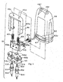
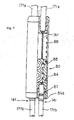
The base end of
In this structure, the gap between the
Claims (14)
- A connecting apparatus for a control cable (14f, 14r) having an inner wire (16f, 16r) that slides within an outer casing (17f, 17r) comprising:a cable sleeve (23) adapted to receive the outer casing (17f, 17r) of the control cable (14f, 14r);a guide (24) having a first end portion and a second end portion, wherein the guide (24) supports the cable sleeve (23) so that the cable sleeve (23) can move toward the first end portion and/or the second end portion; anda biasing device (25) for biasing the cable sleeve (23) toward the second end portion of the guide (24); characterised in thatthe cable sleeve (23) engages with a stop that prevents the cable sleeve (23) and the outer casing (17f, 17r) from moving with the inner wire (16f, 16r) as the tension on the inner wire (16f, 16r) is increased.
- Apparatus according to claim 1, wherein the first end portion of the guide (24) includes a mounting portion (24a, 24b) for fixing the guide (24) to a mounting member (20).
- Apparatus according to claim 2, wherein the mounting portion (24a, 24b) includes a threaded surface.
- Apparatus according to any preceding claim, wherein the apparatus includes a brake lever bracket (20), wherein the first end portion of the guide (24) is mounted to the brake lever bracket (20).
- Apparatus according to claim 4, wherein the apparatus includes a brake lever (21) pivotally connected to the brake lever bracket (20).
- Apparatus according to any preceding claim, wherein the second end portion of the guide (24) is adapted to receive the outer casing (17f, 17r) of the control cable (14f, 14r) therein.
- Apparatus according to any preceding claim, wherein the cable sleeve (23) is disposed within the guide (24), and the apparatus includes a lid (27) disposed at the second end portion of the guide (24) for retaining the cable sleeve (23) within the guide (24).
- Apparatus according to any preceding claim, wherein the biasing device comprises a spring (25) disposed between the guide (24) and the cable sleeve (23).
- Apparatus according to any preceding claim, wherein the apparatus includes a bellows (26) disposed at the second end portion of the guide (24), wherein the bellows (26) is adapted to sealingly engage the outer casing (17f, 17r) of the control cable (14f, 14r).
- Apparatus according to any preceding claim, wherein the stop comprises a shoulder on the guide (24).
- Apparatus according to any preceding claim, wherein the stop comprises a tip of the guide (24).
- Apparatus according to any preceding claim, wherein the cable sleeve (23) comprises a cup-shaped member and a spring sleeve (23a).
- A brake apparatus comprising a first brake lever (12f) adapted for coupling to a first control cable (14f) having a first inner wire (16f) that slides within a first outer casing (17f), and a second brake lever (12r) adapted for coupling to a second control cable (14r) having a second inner wire (16r) that slides within a second outer casing (17r), the first inner wire (16f) and the second inner wire (16r) being coupled together so that movement of one of the first and second inner wires (16f, 16r) causes movement of the other of the first and second inner wires (16f, 16r), and wherein the brake apparatus includes a connecting apparatus according to any one of claims 1 to 12.
- A bicycle brake operating apparatus comprising:a first brake operating device (12f);a first brake cable (14f) having a first inner wire (16f) that slides within a first outer casing (17f), wherein the first inner wire (16f) is coupled to the first brake operating device (12f);a second brake operating device (12r);a second brake cable (14r) having a second inner wire (16r) that slides within a second outer casing (17r), wherein the second inner wire (16r) is coupled to the second brake operating device (12r);a cable connecting unit (15, 65, 80) for operatively connecting the first and second inner wires (16f, 16r) together so that movement of one of the first and second inner wires (16f, 16r) causes movement of the other of the first and second inner wires (16f, 16r); and wherein the apparatus is provided with a connecting apparatus comprising:a cable sleeve (23) adapted to receive the outer casing (17f, 17r) of the control cable (14f, 14r) ;a guide (24) having a first end portion and a second end portion, wherein the guide (24) supports the cable sleeve (23) so that the cable sleeve (23) can move toward the first end portion and/or the second end portion; anda biasing device (25) for biasing the cable sleeve (23) toward the second end portion of the guide (24) so that when one of the first and second brake operating devices (12f, 12r) is operated, the tension in the inner wire (16f, 16r) connected to the other brake operating device (12f, 12r) is maintained.
Applications Claiming Priority (3)
| Application Number | Priority Date | Filing Date | Title |
|---|---|---|---|
| JP2000398491 | 2000-12-27 | ||
| JP2000398491A JP3626681B2 (en) | 2000-12-27 | 2000-12-27 | Bicycle brake cable latch and bicycle brake lever |
| EP01310594A EP1219531B2 (en) | 2000-12-27 | 2001-12-19 | Bicycle brake device |
Related Parent Applications (2)
| Application Number | Title | Priority Date | Filing Date |
|---|---|---|---|
| EP01310594.5 Division | 2001-12-19 | ||
| EP01310594A Division EP1219531B2 (en) | 2000-12-27 | 2001-12-19 | Bicycle brake device |
Publications (3)
| Publication Number | Publication Date |
|---|---|
| EP1431170A2 true EP1431170A2 (en) | 2004-06-23 |
| EP1431170A3 EP1431170A3 (en) | 2005-01-12 |
| EP1431170B1 EP1431170B1 (en) | 2006-08-16 |
Family
ID=18863446
Family Applications (2)
| Application Number | Title | Priority Date | Filing Date |
|---|---|---|---|
| EP01310594A Expired - Lifetime EP1219531B2 (en) | 2000-12-27 | 2001-12-19 | Bicycle brake device |
| EP04007146A Expired - Lifetime EP1431170B1 (en) | 2000-12-27 | 2001-12-19 | Bicycle brake device |
Family Applications Before (1)
| Application Number | Title | Priority Date | Filing Date |
|---|---|---|---|
| EP01310594A Expired - Lifetime EP1219531B2 (en) | 2000-12-27 | 2001-12-19 | Bicycle brake device |
Country Status (7)
| Country | Link |
|---|---|
| US (2) | US6840129B2 (en) |
| EP (2) | EP1219531B2 (en) |
| JP (1) | JP3626681B2 (en) |
| CN (2) | CN100379641C (en) |
| CZ (1) | CZ20014672A3 (en) |
| DE (2) | DE60122393T2 (en) |
| TW (1) | TWI221132B (en) |
Cited By (1)
| Publication number | Priority date | Publication date | Assignee | Title |
|---|---|---|---|---|
| WO2006042442A1 (en) * | 2004-10-22 | 2006-04-27 | Thomas Grandy | Braking device for a two-wheeled or a three-wheeled vehicle |
Families Citing this family (12)
| Publication number | Priority date | Publication date | Assignee | Title |
|---|---|---|---|---|
| JP3740093B2 (en) * | 2002-06-11 | 2006-01-25 | 株式会社シマノ | Bicycle hub brake device |
| EP1388491B1 (en) * | 2002-08-08 | 2009-09-30 | SRAM Deutschland GmbH | Cable connection |
| KR101193257B1 (en) * | 2010-08-09 | 2012-10-19 | 안기인 | Bicycle for the exercise of the upper part of body |
| CN102448805A (en) * | 2009-09-18 | 2012-05-09 | 安基仁 | Bicycle for exercising the upper part of the body |
| TWI381974B (en) * | 2010-01-06 | 2013-01-11 | Ashima Ltd | A device that can be equipped with a hydraulic brake |
| JP2012116227A (en) * | 2010-11-29 | 2012-06-21 | Techway Industrial Co Ltd | Transmission sensing device of gear shift cable for power-assisted bicycle |
| US9651138B2 (en) | 2011-09-30 | 2017-05-16 | Mtd Products Inc. | Speed control assembly for a self-propelled walk-behind lawn mower |
| US8746107B2 (en) * | 2011-10-14 | 2014-06-10 | Shimano Inc. | Bicycle cable structure |
| JP2016000432A (en) * | 2014-06-11 | 2016-01-07 | キヤノン電子株式会社 | Parallel link robot |
| CN104613082A (en) * | 2015-01-28 | 2015-05-13 | 柳州市同进汽车零部件制造有限公司 | Automobile brake cable |
| CN106005210B (en) * | 2016-07-18 | 2019-01-04 | 宁波彰星车辆有限公司 | A kind of bicycle brake safety governor |
| CN106240543A (en) * | 2016-08-30 | 2016-12-21 | 无锡忻润汽车安全系统有限公司 | Drag-line disconnecting prevention structure |
Citations (14)
| Publication number | Priority date | Publication date | Assignee | Title |
|---|---|---|---|---|
| US4066147A (en) * | 1975-06-04 | 1978-01-03 | Hiromitsu Toyomoto | Automatic lubricating device for remotely operable bowden cable |
| US4351418A (en) * | 1980-11-14 | 1982-09-28 | J.C. Penney Company, Inc. | Vehicle brake compensator |
| GB2123501A (en) * | 1982-07-09 | 1984-02-01 | Antony Tewdyr Watkins | A braking system for a cycle, specifically a bicycle |
| US4526057A (en) * | 1982-07-20 | 1985-07-02 | Nissan Motor Co., Ltd. | Reciprocating type push-pull cable arrangement for transmitting longitudinal motion |
| US4833937A (en) * | 1985-04-22 | 1989-05-30 | Shimano Industrial Company Limited | Adjusting device for a control cable for a bicycle |
| US4862999A (en) * | 1987-02-11 | 1989-09-05 | Societe Dite Mbk Industries Societe Nouvelle Motobecane S.A. | Device for braking a bicycle |
| EP0431307A1 (en) * | 1989-12-05 | 1991-06-12 | Fico-Cables, S.A. | Adjustable cable sheath terminal |
| EP0547795A2 (en) * | 1991-12-16 | 1993-06-23 | Kimihiro Tsuchie | Braking device for a cycle |
| DE9320236U1 (en) * | 1993-12-30 | 1994-02-24 | Wahl Markus | Device for actuating Bowden cable mechanics, in particular side pull rim brakes, with more than one actuating lever, or for actuating several mechanics with one or more actuating levers |
| NL9301878A (en) * | 1993-11-01 | 1995-06-01 | Koga B V | Device for limiting a force |
| DE19634432A1 (en) * | 1995-10-11 | 1997-04-17 | Campagnolo Srl | Cycle brake control device |
| US5765446A (en) * | 1995-07-11 | 1998-06-16 | Sram Corporation | Control cable preload and sealing apparatus and system |
| JP2000238686A (en) * | 1999-02-19 | 2000-09-05 | Shimano Inc | Brake control device for vehicle |
| EP1035008A2 (en) * | 1999-03-05 | 2000-09-13 | Shimano Inc. | Braking power modulator for a bicycle brake |
Family Cites Families (36)
| Publication number | Priority date | Publication date | Assignee | Title |
|---|---|---|---|---|
| CH208677A (en) † | 1939-06-03 | 1940-02-15 | Hofer Hans | Braking device on vehicles such as B. Bicycles and Motorcycles. |
| CH264208A (en) † | 1947-01-23 | 1949-09-30 | Rubli Heinrich | Braking device for vehicles with front and rear brakes, in particular for bicycles and motorcycles. |
| CH257927A (en) † | 1947-01-23 | 1948-10-31 | Rubli Heinrich | Braking device for vehicles with front and rear brakes, in particular for bicycles and motorcycles. |
| US2892624A (en) * | 1957-03-21 | 1959-06-30 | American Steel Foundries | Axial load spring |
| FR1538932A (en) † | 1967-10-03 | 1968-09-06 | Control device in particular for the gear change of a derailleur | |
| US3942609A (en) † | 1975-04-14 | 1976-03-09 | Hill Robert H | Safety brake for bicycles |
| US4057127A (en) † | 1975-11-06 | 1977-11-08 | J. C. Penney Company, Inc. | Safety actuating device adapted for two wheeled vehicles |
| JPS5369341A (en) * | 1976-11-29 | 1978-06-20 | Kurosawa Chie | Brake wire connecting means |
| JPS54113143A (en) * | 1978-02-23 | 1979-09-04 | Tanizou Kishi | Oneehanded brake |
| US4480720A (en) † | 1979-09-08 | 1984-11-06 | Shimano Industrial Company Limited | Brake operating device for a bicycle |
| JPS59199384A (en) * | 1983-04-27 | 1984-11-12 | 宮田工業株式会社 | Brake gear for bicycle |
| FR2577330B1 (en) * | 1985-02-13 | 1987-02-20 | Bendix France | MECHANICAL CONTROL DEVICE WITH SELF-ADJUSTING CABLE |
| GB2175657B (en) † | 1985-05-07 | 1989-09-06 | Masataro Sato | Brake system for bicycles |
| JP2537504B2 (en) * | 1987-02-17 | 1996-09-25 | 株式会社シマノ | Brake pressure contact force control device |
| ES2004442A6 (en) * | 1987-07-02 | 1989-01-01 | Pujol & Tarago | Automatic length adjuster for control cables |
| JP2542890B2 (en) | 1988-02-08 | 1996-10-09 | 政太郎 佐藤 | Brake device for bicycle |
| JPH042588A (en) | 1990-04-19 | 1992-01-07 | Kazuo Shibata | Operating force transmission device using control cable |
| JPH04113143A (en) | 1990-08-31 | 1992-04-14 | Kansai Electric Power Co Inc:The | Range device for kitchen |
| JP2901385B2 (en) | 1991-07-15 | 1999-06-07 | 株式会社シマノ | Brake operating device for bicycle |
| JP2901384B2 (en) | 1991-07-15 | 1999-06-07 | 株式会社シマノ | Brake operating device for bicycle |
| JP2901386B2 (en) | 1991-07-15 | 1999-06-07 | 株式会社シマノ | Bicycle braking device |
| US5178033A (en) † | 1991-09-03 | 1993-01-12 | August Kund | Bicycle gear display |
| DE4219286A1 (en) † | 1992-05-21 | 1992-10-22 | Aribert Striegnitz | Brake for pedal bicycles - has freewheel with brake drive, brake force distributor on frame, and brake force limiter |
| US5289794A (en) * | 1992-09-23 | 1994-03-01 | Delco Electronics Corporation | Magnetically aligned transmission shift indicator |
| JP2597741Y2 (en) * | 1993-07-21 | 1999-07-12 | 株式会社シマノ | Bicycle brake lever device |
| JP3354658B2 (en) * | 1993-10-06 | 2002-12-09 | 株式会社シマノ | Bicycle indicator |
| JP3638309B2 (en) | 1994-06-23 | 2005-04-13 | 株式会社シマノ | Bicycle hub brake |
| US5809840A (en) * | 1995-02-14 | 1998-09-22 | Shimano, Inc. | Protective cap system for bicycle cable |
| JPH0948383A (en) * | 1995-08-10 | 1997-02-18 | Juji Hashimoto | Braking force distributing device |
| JP3365910B2 (en) * | 1996-07-23 | 2003-01-14 | 株式会社シマノ | Bicycle display device |
| US5927442A (en) * | 1997-06-02 | 1999-07-27 | Liao; Chi-Chao | Device for controlling the operational sequence of brake assemblies for bicycles |
| US6295888B1 (en) * | 1999-02-16 | 2001-10-02 | Shimano Inc. | Gear indicator for a bicycle |
| US6389925B1 (en) * | 1999-02-16 | 2002-05-21 | Shimano Inc. | Shift operating device |
| US6152266A (en) * | 1999-03-05 | 2000-11-28 | Shimano Inc. | Braking power modulator for a bicycle |
| US6186282B1 (en) | 1999-03-10 | 2001-02-13 | Chih-Chen Juan | Balanced braking system |
| US6328138B1 (en) * | 1999-12-10 | 2001-12-11 | Shimano Inc. | Brake operating device with modulator |
-
2000
- 2000-12-27 JP JP2000398491A patent/JP3626681B2/en not_active Expired - Fee Related
-
2001
- 2001-10-19 TW TW090125948A patent/TWI221132B/en not_active IP Right Cessation
- 2001-12-19 EP EP01310594A patent/EP1219531B2/en not_active Expired - Lifetime
- 2001-12-19 DE DE60122393T patent/DE60122393T2/en not_active Expired - Lifetime
- 2001-12-19 DE DE60105536T patent/DE60105536T3/en not_active Expired - Lifetime
- 2001-12-19 EP EP04007146A patent/EP1431170B1/en not_active Expired - Lifetime
- 2001-12-21 CZ CZ20014672A patent/CZ20014672A3/en unknown
- 2001-12-26 US US10/033,022 patent/US6840129B2/en not_active Expired - Fee Related
- 2001-12-26 CN CNB200510074051XA patent/CN100379641C/en not_active Expired - Fee Related
- 2001-12-26 CN CNB011432950A patent/CN1328110C/en not_active Expired - Fee Related
-
2003
- 2003-10-02 US US10/678,819 patent/US6823758B2/en not_active Expired - Fee Related
Patent Citations (14)
| Publication number | Priority date | Publication date | Assignee | Title |
|---|---|---|---|---|
| US4066147A (en) * | 1975-06-04 | 1978-01-03 | Hiromitsu Toyomoto | Automatic lubricating device for remotely operable bowden cable |
| US4351418A (en) * | 1980-11-14 | 1982-09-28 | J.C. Penney Company, Inc. | Vehicle brake compensator |
| GB2123501A (en) * | 1982-07-09 | 1984-02-01 | Antony Tewdyr Watkins | A braking system for a cycle, specifically a bicycle |
| US4526057A (en) * | 1982-07-20 | 1985-07-02 | Nissan Motor Co., Ltd. | Reciprocating type push-pull cable arrangement for transmitting longitudinal motion |
| US4833937A (en) * | 1985-04-22 | 1989-05-30 | Shimano Industrial Company Limited | Adjusting device for a control cable for a bicycle |
| US4862999A (en) * | 1987-02-11 | 1989-09-05 | Societe Dite Mbk Industries Societe Nouvelle Motobecane S.A. | Device for braking a bicycle |
| EP0431307A1 (en) * | 1989-12-05 | 1991-06-12 | Fico-Cables, S.A. | Adjustable cable sheath terminal |
| EP0547795A2 (en) * | 1991-12-16 | 1993-06-23 | Kimihiro Tsuchie | Braking device for a cycle |
| NL9301878A (en) * | 1993-11-01 | 1995-06-01 | Koga B V | Device for limiting a force |
| DE9320236U1 (en) * | 1993-12-30 | 1994-02-24 | Wahl Markus | Device for actuating Bowden cable mechanics, in particular side pull rim brakes, with more than one actuating lever, or for actuating several mechanics with one or more actuating levers |
| US5765446A (en) * | 1995-07-11 | 1998-06-16 | Sram Corporation | Control cable preload and sealing apparatus and system |
| DE19634432A1 (en) * | 1995-10-11 | 1997-04-17 | Campagnolo Srl | Cycle brake control device |
| JP2000238686A (en) * | 1999-02-19 | 2000-09-05 | Shimano Inc | Brake control device for vehicle |
| EP1035008A2 (en) * | 1999-03-05 | 2000-09-13 | Shimano Inc. | Braking power modulator for a bicycle brake |
Non-Patent Citations (1)
| Title |
|---|
| PATENT ABSTRACTS OF JAPAN vol. 2000, no. 12, 3 January 2001 (2001-01-03) & JP 2000 238686 A (SHIMANO INC), 5 September 2000 (2000-09-05) * |
Cited By (1)
| Publication number | Priority date | Publication date | Assignee | Title |
|---|---|---|---|---|
| WO2006042442A1 (en) * | 2004-10-22 | 2006-04-27 | Thomas Grandy | Braking device for a two-wheeled or a three-wheeled vehicle |
Also Published As
| Publication number | Publication date |
|---|---|
| EP1219531B1 (en) | 2004-09-15 |
| CN1689900A (en) | 2005-11-02 |
| TWI221132B (en) | 2004-09-21 |
| DE60122393D1 (en) | 2006-09-28 |
| CN100379641C (en) | 2008-04-09 |
| EP1431170A3 (en) | 2005-01-12 |
| EP1219531A2 (en) | 2002-07-03 |
| JP2002193176A (en) | 2002-07-10 |
| DE60105536T3 (en) | 2009-07-23 |
| DE60105536T2 (en) | 2005-09-29 |
| EP1219531A3 (en) | 2003-03-05 |
| CN1328110C (en) | 2007-07-25 |
| JP3626681B2 (en) | 2005-03-09 |
| EP1431170B1 (en) | 2006-08-16 |
| US20040084254A1 (en) | 2004-05-06 |
| CZ20014672A3 (en) | 2002-10-16 |
| DE60122393T2 (en) | 2007-09-06 |
| CN1371838A (en) | 2002-10-02 |
| US6840129B2 (en) | 2005-01-11 |
| DE60105536D1 (en) | 2004-10-21 |
| EP1219531B2 (en) | 2008-12-17 |
| US6823758B2 (en) | 2004-11-30 |
| US20020079171A1 (en) | 2002-06-27 |
Similar Documents
| Publication | Publication Date | Title |
|---|---|---|
| EP1219531B1 (en) | Bicycle brake device | |
| EP1595780B2 (en) | Apparatus for mounting a hub brake to a bicycle frame | |
| EP0758433B1 (en) | Adjustable leverage brake lever | |
| CA1066587A (en) | Self-adjusting bike brake operating mechanism | |
| US5476019A (en) | Rotatable handgrip actuating system | |
| US20060194660A1 (en) | Bicycle derailleur with a motion limiting structure | |
| JP3679707B2 (en) | Bicycle brake operating device | |
| US6843741B2 (en) | Bell crank assembly and mounting bracket for a bicycle hub transmission | |
| US7490700B2 (en) | Bicycle motion sensing arrangement | |
| US5117948A (en) | Brake for bicycles | |
| US4674353A (en) | Brake operating device | |
| US6293882B1 (en) | Operating force compensating apparatus for a bicycle transmission | |
| FR2757127A1 (en) | Motorcycle brake control system | |
| EP0791531B1 (en) | Cantilever brake device | |
| JP2004314964A (en) | Braking cable connection device for bicycle and braking system for bicycle | |
| JPH0322355B2 (en) | ||
| FR2689083A3 (en) | Simultaneous cable brake operator for bicycles and mopeds - locks cables together by set screws in body having parallel holes with top cap spring-loaded against cable sheaths |
Legal Events
| Date | Code | Title | Description |
|---|---|---|---|
| PUAI | Public reference made under article 153(3) epc to a published international application that has entered the european phase |
Free format text: ORIGINAL CODE: 0009012 |
|
| 17P | Request for examination filed |
Effective date: 20040325 |
|
| AC | Divisional application: reference to earlier application |
Ref document number: 1219531 Country of ref document: EP Kind code of ref document: P |
|
| AK | Designated contracting states |
Kind code of ref document: A2 Designated state(s): DE FR GB IE IT NL |
|
| PUAL | Search report despatched |
Free format text: ORIGINAL CODE: 0009013 |
|
| AK | Designated contracting states |
Kind code of ref document: A3 Designated state(s): DE FR GB IE IT NL |
|
| 17Q | First examination report despatched |
Effective date: 20050223 |
|
| AKX | Designation fees paid |
Designated state(s): DE FR GB IE IT NL |
|
| GRAP | Despatch of communication of intention to grant a patent |
Free format text: ORIGINAL CODE: EPIDOSNIGR1 |
|
| GRAS | Grant fee paid |
Free format text: ORIGINAL CODE: EPIDOSNIGR3 |
|
| GRAA | (expected) grant |
Free format text: ORIGINAL CODE: 0009210 |
|
| RAP1 | Party data changed (applicant data changed or rights of an application transferred) |
Owner name: SHIMANO INC. |
|
| AC | Divisional application: reference to earlier application |
Ref document number: 1219531 Country of ref document: EP Kind code of ref document: P |
|
| AK | Designated contracting states |
Kind code of ref document: B1 Designated state(s): DE FR GB IE IT NL |
|
| PG25 | Lapsed in a contracting state [announced via postgrant information from national office to epo] |
Ref country code: IT Free format text: LAPSE BECAUSE OF FAILURE TO SUBMIT A TRANSLATION OF THE DESCRIPTION OR TO PAY THE FEE WITHIN THE PRESCRIBED TIME-LIMIT;WARNING: LAPSES OF ITALIAN PATENTS WITH EFFECTIVE DATE BEFORE 2007 MAY HAVE OCCURRED AT ANY TIME BEFORE 2007. THE CORRECT EFFECTIVE DATE MAY BE DIFFERENT FROM THE ONE RECORDED. Effective date: 20060816 |
|
| REG | Reference to a national code |
Ref country code: GB Ref legal event code: FG4D |
|
| REG | Reference to a national code |
Ref country code: IE Ref legal event code: FG4D |
|
| REF | Corresponds to: |
Ref document number: 60122393 Country of ref document: DE Date of ref document: 20060928 Kind code of ref document: P |
|
| PG25 | Lapsed in a contracting state [announced via postgrant information from national office to epo] |
Ref country code: IE Free format text: LAPSE BECAUSE OF NON-PAYMENT OF DUE FEES Effective date: 20061219 |
|
| EN | Fr: translation not filed | ||
| PLBE | No opposition filed within time limit |
Free format text: ORIGINAL CODE: 0009261 |
|
| STAA | Information on the status of an ep patent application or granted ep patent |
Free format text: STATUS: NO OPPOSITION FILED WITHIN TIME LIMIT |
|
| 26N | No opposition filed |
Effective date: 20070518 |
|
| GBPC | Gb: european patent ceased through non-payment of renewal fee |
Effective date: 20061219 |
|
| PG25 | Lapsed in a contracting state [announced via postgrant information from national office to epo] |
Ref country code: GB Free format text: LAPSE BECAUSE OF NON-PAYMENT OF DUE FEES Effective date: 20061219 |
|
| PG25 | Lapsed in a contracting state [announced via postgrant information from national office to epo] |
Ref country code: FR Free format text: LAPSE BECAUSE OF FAILURE TO SUBMIT A TRANSLATION OF THE DESCRIPTION OR TO PAY THE FEE WITHIN THE PRESCRIBED TIME-LIMIT Effective date: 20070511 |
|
| PG25 | Lapsed in a contracting state [announced via postgrant information from national office to epo] |
Ref country code: FR Free format text: LAPSE BECAUSE OF FAILURE TO SUBMIT A TRANSLATION OF THE DESCRIPTION OR TO PAY THE FEE WITHIN THE PRESCRIBED TIME-LIMIT Effective date: 20060816 |
|
| PGFP | Annual fee paid to national office [announced via postgrant information from national office to epo] |
Ref country code: NL Payment date: 20081215 Year of fee payment: 8 |
|
| REG | Reference to a national code |
Ref country code: NL Ref legal event code: V1 Effective date: 20100701 |
|
| PG25 | Lapsed in a contracting state [announced via postgrant information from national office to epo] |
Ref country code: NL Free format text: LAPSE BECAUSE OF NON-PAYMENT OF DUE FEES Effective date: 20100701 |
|
| PGFP | Annual fee paid to national office [announced via postgrant information from national office to epo] |
Ref country code: DE Payment date: 20171212 Year of fee payment: 17 |
|
| REG | Reference to a national code |
Ref country code: DE Ref legal event code: R119 Ref document number: 60122393 Country of ref document: DE |
|
| PG25 | Lapsed in a contracting state [announced via postgrant information from national office to epo] |
Ref country code: DE Free format text: LAPSE BECAUSE OF NON-PAYMENT OF DUE FEES Effective date: 20190702 |