EP1430972A1 - Wire for wired sheet glass and method of manufacturing the wire - Google Patents
Wire for wired sheet glass and method of manufacturing the wire Download PDFInfo
- Publication number
- EP1430972A1 EP1430972A1 EP02800273A EP02800273A EP1430972A1 EP 1430972 A1 EP1430972 A1 EP 1430972A1 EP 02800273 A EP02800273 A EP 02800273A EP 02800273 A EP02800273 A EP 02800273A EP 1430972 A1 EP1430972 A1 EP 1430972A1
- Authority
- EP
- European Patent Office
- Prior art keywords
- mesh
- wires
- wired glass
- producing
- glass
- Prior art date
- Legal status (The legal status is an assumption and is not a legal conclusion. Google has not performed a legal analysis and makes no representation as to the accuracy of the status listed.)
- Granted
Links
Images





Classifications
-
- C—CHEMISTRY; METALLURGY
- C03—GLASS; MINERAL OR SLAG WOOL
- C03C—CHEMICAL COMPOSITION OF GLASSES, GLAZES OR VITREOUS ENAMELS; SURFACE TREATMENT OF GLASS; SURFACE TREATMENT OF FIBRES OR FILAMENTS MADE FROM GLASS, MINERALS OR SLAGS; JOINING GLASS TO GLASS OR OTHER MATERIALS
- C03C14/00—Glass compositions containing a non-glass component, e.g. compositions containing fibres, filaments, whiskers, platelets, or the like, dispersed in a glass matrix
-
- B—PERFORMING OPERATIONS; TRANSPORTING
- B21—MECHANICAL METAL-WORKING WITHOUT ESSENTIALLY REMOVING MATERIAL; PUNCHING METAL
- B21F—WORKING OR PROCESSING OF METAL WIRE
- B21F11/00—Cutting wire
-
- B—PERFORMING OPERATIONS; TRANSPORTING
- B21—MECHANICAL METAL-WORKING WITHOUT ESSENTIALLY REMOVING MATERIAL; PUNCHING METAL
- B21F—WORKING OR PROCESSING OF METAL WIRE
- B21F27/00—Making wire network, i.e. wire nets
- B21F27/08—Making wire network, i.e. wire nets with additional connecting elements or material at crossings
- B21F27/10—Making wire network, i.e. wire nets with additional connecting elements or material at crossings with soldered or welded crossings
-
- B—PERFORMING OPERATIONS; TRANSPORTING
- B21—MECHANICAL METAL-WORKING WITHOUT ESSENTIALLY REMOVING MATERIAL; PUNCHING METAL
- B21F—WORKING OR PROCESSING OF METAL WIRE
- B21F27/00—Making wire network, i.e. wire nets
- B21F27/12—Making special types or portions of network by methods or means specially adapted therefor
- B21F27/22—Making special types or portions of network by methods or means specially adapted therefor of network for wire-reinforced glass or the like
-
- B—PERFORMING OPERATIONS; TRANSPORTING
- B21—MECHANICAL METAL-WORKING WITHOUT ESSENTIALLY REMOVING MATERIAL; PUNCHING METAL
- B21F—WORKING OR PROCESSING OF METAL WIRE
- B21F33/00—Tools or devices specially designed for handling or processing wire fabrics or the like
-
- B—PERFORMING OPERATIONS; TRANSPORTING
- B21—MECHANICAL METAL-WORKING WITHOUT ESSENTIALLY REMOVING MATERIAL; PUNCHING METAL
- B21F—WORKING OR PROCESSING OF METAL WIRE
- B21F33/00—Tools or devices specially designed for handling or processing wire fabrics or the like
- B21F33/002—Coiling or packing wire network
-
- B—PERFORMING OPERATIONS; TRANSPORTING
- B21—MECHANICAL METAL-WORKING WITHOUT ESSENTIALLY REMOVING MATERIAL; PUNCHING METAL
- B21F—WORKING OR PROCESSING OF METAL WIRE
- B21F33/00—Tools or devices specially designed for handling or processing wire fabrics or the like
- B21F33/005—Cutting wire network
-
- C—CHEMISTRY; METALLURGY
- C03—GLASS; MINERAL OR SLAG WOOL
- C03B—MANUFACTURE, SHAPING, OR SUPPLEMENTARY PROCESSES
- C03B13/00—Rolling molten glass, i.e. where the molten glass is shaped by rolling
- C03B13/12—Rolling glass with enclosures, e.g. wire, bubbles, fibres, particles or asbestos
Definitions
- the present invention relates to a mesh for a wired glass, a process for producing it, a wired glass and a process for producing a polished wired glass.
- wired glass such as a rhombus-meshed wired glass or a square-meshed wired glass, a stranded wired glass or a polished wired glass or polished stranded wired glass having both sides polished extremely smoothly, for a window for an architectural structure or the like.
- a wired glass is produced by inserting an iron mesh having a square meshwork in a ribbon glass when the ribbon glass is molded from a molten glass by rolling, gradually cooling the ribbon glass and cutting it to have a predetermined size.
- the iron mesh to be inserted in a wired glass has conventionally been produced by netting an iron wire having a diameter of from 0.5 to 0.6 mm to have a predetermined mesh size.
- a rhombus-meshed wired glass is a glass inserted with a mesh having a rhombic meshwork in which wires are arranged obliquely with respect to the moving direction of the ribbon glass, and one of the diagonal lines is substantially in parallel to the moving direction.
- this rhombic meshwork is rendered to be an obliquely arranged substantially square meshwork by being stretched in the moving direction when it is inserted in the ribbon glass.
- a square-meshed wired glass means a glass plate in which a mesh is inserted so that orthogonally crossed wires are each substantially in parallel or substantially perpendicular to the moving direction of the ribbon glass when the wires constituting the mesh are net orthogonally, for example.
- a stranded wired glass is different from the above wired glasses in that instead of an iron mesh, a plurality of stainless steel wires having a diameter of 0.4 mm are inserted in parallel in a ribbon glass so as to be substantially in parallel to its moving direction.
- a polished wired glass or a polished stranded wired glass is produced by continuously polishing both sides of a wired glass or a stranded wired glass respectively.
- a wired glass or a stranded wired glass having typically a width of from 2.5 to 3 m is attached to a table by means of gypsum etc., and one side of the glass is polished by polishing machines (for example, constituted by from about 15 to 30 grinding machines and from about 15 to 50 polishing machines) disposed in line as the table is moved at a moving speed of from 3 to 10 m/min. After the polishing of one side is finished, the glass sheet is removed from the table, and its unpolished side is polished in the same manner.
- a mesh for a wired glass comprising stainless steel wires crossed one another, wherein the diameter of the wires is within a range of from 0.30 to 0.45 mm, and intersections of the wires are welded.
- the mesh for a wired glass wherein the thickness of each intersection is from 82 to 97% of the sum of diameters of two intercrossed wires.
- the mesh for a wired glass wherein the wires have an average linear expansion coefficient of at most 14 ⁇ 10 -6 /°C at a temperature of from 20 to 700°C and a tensile strength of at most 200 N/mm 2 at 700°C.
- the mesh for a wired glass wherein the wires consist essentially of from 74 to 83 % of Fe, from 0.2 to 8 % of Ni, from 16 to 25 % of Cr, from 0.5 to 2 % of Mn and from 0 to 3 % of Mo represented by mass percentage.
- a process for continuously producing a mesh for a wired glass, comprising stainless steel wires crossed one another said process comprises:
- the process for producing a mesh for a wired glass wherein the width of each groove at its bottom is from 1.1 to 2 times the diameter of the wires to be fitted, the width of the groove at its top is at least 2 times the diameter of said wires, and the width of the groove at its other portions is at least 1.1 times the diameter of said wires.
- the process for producing a mesh for a wired glass wherein the welding of intersections in said wire-intercrossed product is carried out by means of a spot welding.
- the process for producing a mesh for a wired glass wherein the thickness of the welded intersections is from 82 to 97% of the sum of diameters of two intercrossed wires.
- the process for producing a mesh for a wired glass wherein the diameter of the wires is from 0.30 to 0.45 mm.
- the process for producing a mesh for a wired glass wherein the wires have an average linear expansion coefficient of at most 14 ⁇ 10 -6 /°C at a temperature of from 20 to 700°C and a tensile strength of at most 200 N/mm 2 at 700°C.
- the process for producing a mesh for a wired glass wherein the wires consist essentially of from 74 to 83 % of Fe, from 0.2 to 8 % of Ni, from 16 to 25 % of Cr, from 0.5 to 2 % of Mn and from 0 to 3 of Mo represented by mass percentage.
- a conveying speed V 2 of the mesh having welded intersections is controlled to be equal to a conveying speed V 1 of said wire intercrossed product at said cylindrical roll.
- the process for producing a mesh for a wired glass wherein the mesh having welded intersections is retrieved by a retrieving roll, and the rotation of said retrieving roll is controlled so that the retrieving length of the mesh from the time when said V 1 is 0, is equal to the moving distance in a circumferential direction of the cylindrical roll from the circumferential position when V 1 is 0.
- the process for producing a mesh for a wired glass wherein the mesh having welded intersections is retrieved by a retrieving roll, and said mesh is pulled by the retrieving roll to an extent that V 2 stays 0, when V 1 is 0.
- the process for producing a mesh for a wired glass wherein the mesh is retrieved through a tensioner.
- the tensioner has a vertically movable rotational roller in contact with the mesh, and the vertical position of the roller is controlled to suppress a slack of the mesh.
- the wired glass of the present invention is a wired glass wherein the mesh for a wired glass of the present invention is inserted therein, or a wired glass wherein a mesh for a wired glass produced by "a process for producing a mesh for a wired glass" of the present invention is inserted therein.
- the process for producing a polished wired glass according to the present invention is a process for producing a polished wired glass characterized by polishing one side or both sides of the wired glass of the present invention.
- the inventors of the present application have conducted extensive studies as to the reason why an industrial production of a wired glass employing a mesh made of stainless steel wires has not been successful. As a result, they have found that the unsuccessful industrial production has been derived from the fact that employing a stainless steel mesh instead of a conventional iron mesh deteriorates cutting properties of the wired glass. Thus, the present invention has been able to achieve.
- a numerical symbol 10 designates a wired glass
- 11 designates a wire
- 12 designates a mesh (a mesh for a wired glass)
- 36 designates a cylindrical roll
- 34 designates a retrieving roll
- 37 designates a groove
- 51 designates a detecting means
- 52 designates an AC servomotor
- 55 designates a tensioner
- 65 designates a contacting means
- 70 designates a salvage.
- a wired glass 10 as a first embodiment of the present invention is a glass sheet in which a mesh 12 for a wired glass formed by crossing a large number of stainless steel wires 11 one another (hereinafter, referred simply to as a mesh 12) is inserted.
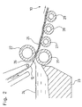
- the wired glass 10 is, for example, produced in the following manner. Namely, as illustrating in Fig. 2, molten glass 24 is taken out from a front end of a tank 23 and molded to be a plate-like shape by means of a pair of rolling rolls 21 and 22 to obtain a ribbon glass 25. At this time, a mesh 12 having a square-meshwork is inserted into a buildup 26 of molten glass 24 formed just before the rolling rolls 21 and 22.
- the ribbon glass 25 in which the mesh 12 is inserted is conveyed by tray rolls 27, 28 and 29 to a lehr, not shown, gradually cooled and cut into a wired glass having a predetermined size.
- Fig. 2 illustrates a case where a mesh is inserted in a single-layer glass.
- a process for industrially producing a wired glass is not limited to this, and may be a sandwich method of inserting the mesh between layers of a two-layered glass.
- each of the intersections 13 of the wires 11 is fixed by an electric resistance welding such as a spot welding.
- an electric resistance welding such as a spot welding.
- the wired glass 10 is, for example, a rhombus-meshed wired glass in which a mesh 12 having a rhombus meshwork of wires 11 is inserted so that the wires 11 are arranged obliquely with respect to the moving direction of the ribbon glass 25 (refer to Fig. 2), one of the diagonal lines of the mesh is substantially in parallel to the moving direction of the ribbon glass 25, and the other diagonal line is substantially perpendicular to the moving direction, or a square-meshed wired glass in which a mesh 12 is inserted so that the wires 11 are substantially in parallel or substantially perpendicular to the moving direction of the ribbon glass 25.
- the wired glass 10 illustrated in Fig. 1 is a square-meshed wired glass.
- the meshwork in this specification is not limited to be one having a square, a rectangular or a rhombus shape, but it includes one having a parallelogram or a polygonal shape.
- the diameter of the wire 11 is at most 0.30 mm, there is a risk that the wires are excessively fused to cause breaking at a time of welding the intersection 13.
- the diameter is preferably at least 0.33 mm. If the diameter of the wires 11 exceeds 0.45 mm, cutting of the wired glass 10 becomes difficult due to the presence of the wires 11 as an obstruction.
- the diameter is preferably at most 0.40 mm, more preferably at most 0.39 mm.
- the cross-sectional shape of the wires 11 is usually a circular shape, but it may, for example, be an ellipsoidal or a polygonal shape. In a case of a non-circular cross-section, the average of the maximum width and the minimum width is designated as the diameter.
- the thickness H2 of the welded intersection 13, is preferably from 82 to 97% of the sum H1 of diameters of two wires 11 and 11 intercrossing at the intersection 13. If it is less than 82%, there is a risk that the wires 11 are excessively fused to cause breaking. H2 is more preferably at least 87% of H1. If it exceeds 97%, there is a risk that the welded portion comes off. The proportion is more preferably at most 95%.
- the wire 11 preferably has an average linear expansion coefficient ⁇ of at most 14 ⁇ 10 -6 /°C at a temperature of from 20 to 700°C and a tensile strength S of at most 200 N/mm 2 at 700°C. If these parameters are out of these ranges, there is a risk that the ribbon glass 25 waves, or the surface irregularities of the ribbon glass 25 increase.
- ⁇ is preferably at most 13 ⁇ 10 -6 /°C. Further, ⁇ is preferably at least 10 ⁇ 10 -6 /°C, more preferably at least 11 ⁇ 10 -6 /°C. It is particularly preferably from 11 ⁇ 10 -6 to 13 ⁇ 10 -6 /°C.
- S is more preferably at most 150 N/mm 2 , particularly preferably at most 100 N/mm 2 . Further, S is preferably at least 50 N/mm 2 , more preferably at most 70 N/mm 2 .
- the tensile strength is a measured value by a method specified in JIS G4309-8.1 tensile test.
- the temperature of the ribbon glass is typically 700°C immediately after it is shaped by water-cooled rolling rolls 21 and 22.
- the ribbon glass is quickly consolidated as it is cooled to a temperature below 700°C. If ⁇ is limited within the above range, the difference of the expansion coefficient between the ribbon glass 25 and the wires 11 at a time of this cooling step becomes small.
- the tensile force of the conveyed ribbon glass 25 which pulls the mesh 12 inserted in the ribbon glass 25 becomes larger than the tensile strength S of the wires 11 constituting the mesh 12.
- the wires 11 are extended by a plastic deformation, and a relative shrink amount of the wire 11 with respect to the ribbon glass 25 by a consecutively conducted cooling step, becomes smaller by the amount of the above extension, whereby the above waving is suppressed or the surface irregularities are reduced.
- the wire 11 preferably consists essentially of from 74 to 83% of Fe, from 0.2 to 8% of Ni, from 16 to 25% of Cr, from 0.5 to 2% of Mn and from 0 to 3% of Mo represented by mass percentage.
- a preferred embodiment is described as follows.
- the percentage of Ni exceeds 8%, a magnetic separation of the wire 11 becomes difficult, and a recovery of the wire 11 to be performed after crashing the wired glass 10 for recycling becomes difficult.
- the percentage is preferably at most 4%. If it is less than 0.2%, the corrosion resistance of the wire 11 is reduced.
- the percentage of Cr is less than 16%, the corrosion resistance of the wire 11 is reduced. If it exceeds 25%, the magnetic separation of the wire 11 becomes difficult. It is preferably at most 20%.
- the percentage of Mn is less than 0.5%, a crack is likely to take place in the glass around the wire 11. If it exceeds 2%, the wire tends to be embrittled. It is preferably at most 1%.
- Mo is not essential to the wire 11, but it may be contained at most 3% in order to improve the corrosion resistance of the wire 11. If it exceeds 3%, the workability of the wire 11 decreases. If Mo is contained, the content is preferably at least 0.5%.
- the wire 11 in the above preferred embodiment consists essentially of the above components, but it may contain other components within a range not impairing the object of the present invention.
- C, Al, Si, P and Ti may be contained at a level of impurities.
- the percentage of C is preferably at most 0.1%. If it exceeds 0.1%, there is a risk that bubbles are formed in the glass. It is preferably at most 0.01%.
- the wire 11 constituting the mesh 12 may be plated with Sn, Cr or Ni etc. However, since such a process increases the number of production steps of the mesh 12, it is preferably that the mesh 12 is not plated from this viewpoint.
- Fig. 3 shows a production apparatus 30 for producing the mesh 12 of the present invention.
- the mesh 12 exemplified here is a mesh for a rhombus-meshed wired glass.
- the production apparatus 30 comprises a wire reel-out portion 31 for reeling out and intercrossing stainless wires 11 to form a wire-intercrossed product 14, a restricting means 32 for restricting the relative position of each of these wires 11, a fixing means 33 for welding and fixing the intersections 13 of each of the wires 11 to form a mesh 12, and a retrieving roll 34 for retrieving the mesh 12 as it is pulled towards the lower right direction in Fig. 3.
- the wire reeling-out portion 31 has a lower wire slipe 35A and an upper wire slipe 35B for pulling out the wire 11 from a resin bobbin, not shown, around which the wire 11 is wound, and a conveyer 35C for conveying a wire-intercrossed product 14 constituted by the wires 11 intercrossed by the lower wire slipe 35A and the upper wire slipe 35B.
- the lower wire slipe 35A and the upper wire slipe 35B are arranged at an angle of about 45° with different orientations with respect to the conveying direction of the mesh 12 being produced. Therefore, the lower wire slipe 35A and the upper wire slipe 35B arrange the wire 11 at an angle of about 45° with different orientations at a predetermined interval with respect to the conveying direction of the mesh being produced.
- the wire reeling-out portion 31 is adapted to intercross and arrange each wires 11 so that one of the diagonal lines of the substantially rhombic meshwork becomes parallel to the conveying direction.
- the conveyer 35C has a plurality of plates 35D having a predetermined width disposed in an endless truck, and is adapted to hook the wires 11 at both ends in the longitudinal direction of each of the plates 35D and perform a reciprocating movement, whereby predetermined interval of the wires 11 can be maintained.
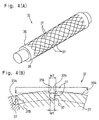
- the restricting means 32 is a cylindrical roll 36 disposed across, preferably, perpendicular to the conveying direction of the mesh 12.
- a large number of grooves 37 are formed in an outer periphery 36A of the cylindrical roll 36.
- the cylindrical roll 36 is rotatable around the axial center of the cylindrical roll 36.
- each of the grooves 37 has a substantially V-shaped cross-section having a pair of walls 37A and 37B facing each other so that the groove 37 becomes thinner towards the axial center of the cylindrical roll 36. Namely, the width of the groove 37 is reduced from the top of the groove 37 towards its bottom.
- the width W1 at the bottom of the groove 37 is from 1.1 to 2 times, preferably from 1.1 to 1.8 times the diameter of the wire 11, and the width W2 at the top of the groove 37 is more than 2 times the diameter of the wire 11, preferably from 4 to 9 times.
- W2 is the maximum width of the groove 37 in the direction of the depth in Fig. 4(B).
- the width of the groove 37 excluding the bottom and top is more than 1.1 times the diameter of the wire 11.
- the grooves 37 are formed in a spiral form intercrossing with a predetermined interval along the outer periphery 36A of the cylindrical roll 36.
- the predetermined interval corresponds the distance between wires 11 constituting the mesh 12, namely, it is equal to the mesh size of the mesh 12.
- the cylindrical roll 36 is rotated around its own axis in a state that each of the wires 11 is accommodated in each of the grooves 37, namely, in a state that the wire-intercrossed product 14 is fit in the grooves 37, whereby each of the wires 11 is continuously aligned and conveyed to a fixing means 33 in the next step.
- W1 of the grooves 37 is from 1.1 to 2 times the diameter of the wire 11
- W2 of the grooves 37 is more than 2 times the diameter of the wire 11
- the width of the groove 37 at a portion except its top and bottom is more than 1.1 times the diameter of the wire 11
- the wire 11 is securely held in contact with the walls 37A and 37B, and each of the wires 11 is aligned with predetermined intervals.
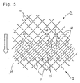
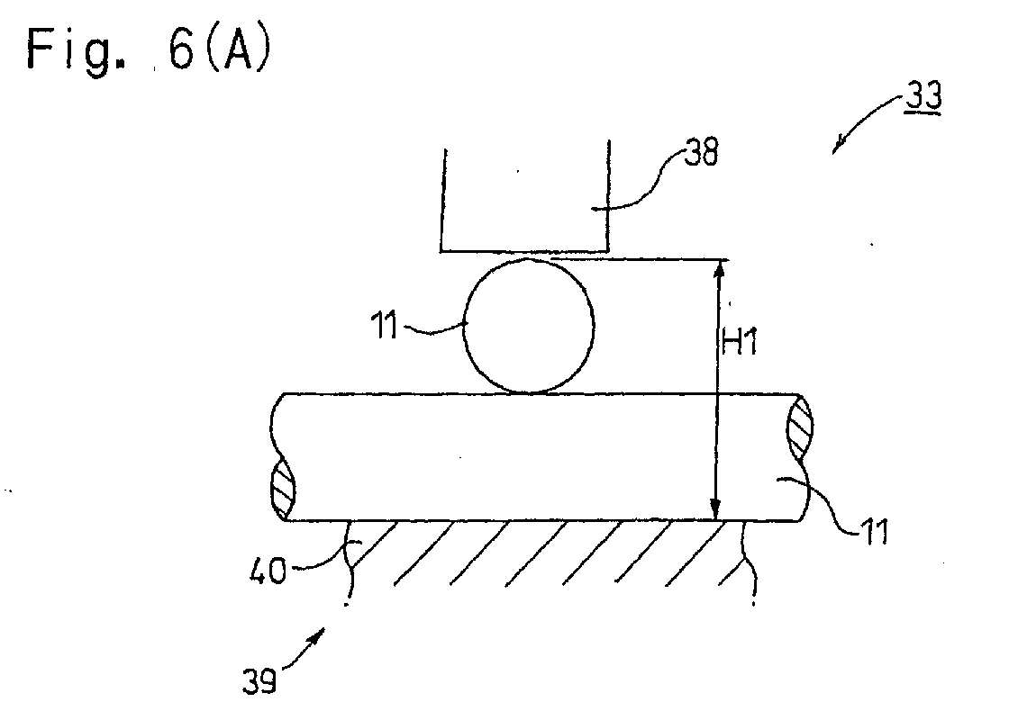
- the fixing means 33 is a spot welding machine having an upper electrode assembly 38 and a lower electrode assembly 39 for pinching the intersections 13 of wires 11 of the wire-intercrossed product 14 after having been passed through the restricting means 32.
- the lower electrode assembly 39 has a plurality of electrode units 40 each having a substantially rectangular surface disposed at an angle of about 45° with respect to the feeding direction in the process indicated by an arrow in Fig. 5. These electrode units 40 are disposed in parallel one another to weld four intersection 13 of wires 11 at a time to fix them.
- Each of the electrode unit 40 which can weld these four intersections 13 at a time may be one having two electrodes each of which can weld two intersections, or may be one having four electrodes each can weld one intersection.
- the pinching pressure, the current and the voltage can be controlled independently.
- the wire 11 has a large diameter variation so that the wire has a smaller diameter or if there is a possibility that an intersection 13 deviates from the center of the electrode, it is preferred to employ an electrode unit having two electrodes each can weld two intersections, or an electrode unit having four electrodes each can weld one intersection.
- H2 within a range of from 82 to 97% of H1
- intersections 13 have been made with respect to the case of welding four intersections 13 at the same time or sequentially.
- the number of intersections 13 in such process is not limited to four, and may be one, two, three or at least five. It is preferred to be at least two to obtain a large speed to produce the mesh.
- the fixing means 33 is constituted so that the upper electrode assembly 38 can move closer to or apart from the lower electrode assembly 39 in a fixed state.
- the electric current and a proximity time (a time of pinching the wire 11) of the upper electrode assembly 38 and the lower electrode assembly 39 contact portions of two intercrossed wires 11 and 11 can be melted into each other so that the built-up thickness of the two intercrossed wires 11 at the intersection 13, namely the thickness H2 of the welded intersection 13 (refer to Fig. 6(B)), becomes from 3 to 18% smaller than the sum H1 of diameters of the intercrossed wires 11 and 11 at the intersection 13 (refer to Fig. 6(A)).
- the H2 thickness is from 82 to 97% of the thickness H1.
- the mesh 12 thus produced is cut to remove both ends 12A in the conveying direction, retrieved by a retrieving roll 34, and used in the production process of the wired glass 10 as illustrated in Fig. 2.
- the wires 11 constituting the mesh 12 have a diameter of from 0.30 mm to 0.45 mm, the intersections of the wires 11 are welded, and therefore there is no risk of causing error of relative position of the wires 11 when the mesh 12 is inserted in the ribbon glass 25, and a wired glass 10 having a good cutting property comparable with a conventional wired glass having an iron mesh can be obtained.
- the contact portions of the two intercrossed wires 11 are melted into each other so that the thickness H2 at the intersection 13 becomes from 82 to 97% of the sum H1 of the diameters of the intercrossed wires 11 and 11 at the intersection 13, whereby there is less risk that the welded portion comes off as compared with a case where H2 exceeds 97% of H1, and there is less risk of breaking off of the wires 11 as compared with the case where it is less than 82%.
- intervals of the wires 11 can be maintained constant by making the plurality of grooves formed on the cylindrical surface 36A of the rotatable cylindrical roll 36 hold each of the wires 11 constituting the wire-intercrossed product 14 so that the wires 11 are continuously aligned and conveyed.
- each of the grooves 37 is a substantially V-shape
- the wire 11 is securely held at the center of the cross section of the groove 37.
- the wires 11 are held securely with a predetermined intervals.
- intersections 13 at which wires 11 are crossed are fixed by a spot welding, whereby these intersections 13 can be fixed. Further since a plurality of the intersections 13 are spot-welded at the same time, a high-speed production of the mesh 12 can be achieved.
- the present invention is not limited to the above first embodiment, and can be modified or improved appropriately.
- a square-meshed wired glass is exemplified as the wired glass 10, but the present invention can be applied also to a rhombus-meshed wired glass.
- a cylindrical roll 70 illustrated in Fig. 7 or a cylindrical roll 80 illustrated in Fig. 8 may be exemplified.
- the cylindrical roll 70 shown in Fig. 7 has a large number of grooves 77 formed in a cylindrical surface 70A in a circumferential direction.
- the cylindrical roll 80 shown in Fig. 8 has a large number of grooves 88 formed in circumferential and the axial directions in a cylindrical surface 80A.
- the material, shape, dimension, melting amount, type, number, disposed location, etc. of the wires, mesh, intersections, cylindrical roll, grooves etc. exemplified in the first embodiment can be optionally selected and not limited so long as the object of the present invention can be achieved.
- the method of polishing one or both sides of the wired glass of the present invention is not particularly limited.
- the above-mentioned single-side continuous polishing method may be mentioned.
- a method for polishing both sides of the wired glass of the present invention a method of applying the above-mentioned single-side continuous polishing method once to each of both sides of the wired glass, or a double-side continuous polishing method may be mentioned.
- ⁇ is at most 14 ⁇ 10 -6 /°C and S is at most 200 N/mm 2 .
- S is at most 200 N/mm 2 .
- a meshed wired glass means one whose both surfaces are polished to be extremely smooth according to Japanese Industrial Standards as described above.
- the present invention includes one whose only one side is polished and the other side is not polished.
- a mesh for a wired glass having a rhombus meshwork with a mesh size of 19.35 mm was produced according to the method described with reference to Figs. 3, 4, 5 and 6.
- the above wire has an ⁇ of 12.9 ⁇ 10 -6 /°C and an S of 83 N/mm 2 .
- Each of grooves of a cylindrical roll employed for producing the mesh has a substantially V-shape as shown in Fig. 4(B), and has a W1 of 0.5 mm and a W2 of 2.5 mm.
- the thickness H2 of welded intersections of the obtained mesh was 0.63 mm and accordingly, H2/H1 was 90%.
- this mesh was inserted into a molten glass from its bottom side to produce a wired glass, differently from Fig. 2. Namely, making contact portions of a pair of rolling rolls lower than the liquid surface of the molten glass to form a long pillow-shaped buildup (bolster) of molten glass in the upstream side of the contact portions of lower rolling roll, the mesh was inserted into the bolster.
- the temperature of the bolster was from 900 to 1,200°C, and the temperature of the ribbon glass was 700°C after passed through the pair of rolling rolls.
- the length of the mesh inserted was 90 m
- the diameter of wires of the mesh was 0.35 mm
- the thickness and the width of the ribbon glass were respectively 6.8 mm and 2.7 m.
- the ribbon glass was gradually cooled and then cut to obtain a wired glass having a size of 2.54 m ⁇ 1.80 m.
- the cutting was carried out without any problem and the cutting property was good.
- the irregularities of the products of the present invention are apparently smaller than those of the conventional product 1.
- the polishing efficiency of the product of the present invention was apparently improved as compared with the conventional product 1.
- a slack was formed at a portion 50 as a part of the mesh 12 between the cylindrical roll 36 and the retrieving roll 34.
- the slack propagates to a part of the mesh 12 already wound around the retrieving roll 34.
- the mesh 12 is slacked so that the part already wound around the retrieving roll 34 and another part wound successively thereon are apart from each other in a direction of the thickness.
- a meshwork part 50 as a part of the mesh 12 will be deformed as illustrated in Fig. 10.
- the deformation of the meshwork of the mesh 12 occurs in an area of narrow width.
- a relatively long range L1 of the mesh 12 may become defective.
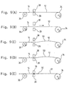
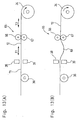
- the mesh 12 is intermittently fed as illustrated in Figs. 9(A) to 9(E), there is a risk that the mesh 12 is loosely wound or unevenly wound. If the mesh 12 is loosely wound or unevenly wound, the roll diameter of the mesh 12 wound around the retrieving roll 34 becomes large. If it is loosely wound, the length of the mesh 12 per each roll becomes short.
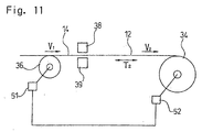
- the rotating state of the cylindrical roll 36 is detected by a detecting means 51, and according to the detected rotating status, the rotating status of the retrieving roll 34 is changed by a control means 52 so that the conveying speed V 1 of the wire-intercrossed product 14 is equal to the conveying speed V 2 of the mesh 12 as a wire intercrossed product 14 having welded intersections.
- the rotating state of the cylindrical roll 36 may be detected, for example, by employing a rotary encoder as the detecting means 51, to obtain a peripheral velocity of the cylindrical roll 36 from the measurement results.
- the circumferential velocity is equal to V 1 .
- the rotating status of the retrieving roll 34 is changed, for example, by employing an AC servomotor as the control means 52 and supplying an input signal obtained by the above detection result so that the feeding speed V 2 of the mesh 12 becomes equal to V 1 .
- the following method is exemplified. Namely, at a time the intersections being welded, the conveying of the wire-intercrossed product 14 is stopped whereby V 1 becomes 0. A circumferential position of the cylindrical roll 36 at this time is memorized.
- the time when the above feeding is stopped is simply referred to as a stand still time, and the circumferential position memorized is referred to as the circumferential position at stand still time.
- each circumferential position of the cylindrical roll 36 at intervals of, for example, of 0.1 second is calculated based on the above circumferential position at stand still time.
- the above circumferential position is a variation amount of the circumferential position (a circumferential moving distance) from the circumferential position at stand still time.
- the information including the circumferential position thus obtained by the calculation is supplied to the control means 52 such as an AC servomotor, and the rotating state of the retrieving roll 34 is changed by the control means 52 based on the above information at, for example, every 0.1 second so that the variation amount of the circumferential position of the mesh 12 at the retrieving roll 34 is equal to the variation amount of its circumferential position at the cylindrical roll 36.
- the control means 52 such as an AC servomotor
- V 1 is 0 and V 2 also 0 as it is equal to V 1 .
- T 2 is controlled so that T 2 becomes a predetermined value while satisfying the condition that V 2 is maintained 0.
- the loose winding or the uneven winding of the mesh 12 around the retrieving roll 34 can be prevented.
- the mesh 12 is densely wound around the retrieving roll 34.
- the length of the mesh 12 per roll can be made longer. Further, the deformation of the meshwork becomes less likely to occur.
- the calculated diameter is a theoretical roll diameter calculated based on the length of the retrieved mesh (mesh length) and the wire diameter.
- a first tension T 1 to the mesh 12 between the cylindrical roll 36 and a tensioner 55 is made equal to the second tension T 2 to the mesh 12 between the tensioner 55 and the retrieving roll 34.
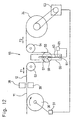
- a shaft 58 is movably fit in a guide groove 57 of a guide member 56, and a vertically movable rotational roller 59 is attached to the shaft 58. Further, the upper end of a ball screw 60 is attached to the shaft 58, the lower end of the ball screw 60 is attached either to a position detection means or a load detection means 61, and an upstream rotational roller 63 and a downstream rotational roller 64 are provided upstream side and downstream side of the guide member 56 respectively.
- the tensioner 55 is provided with the vertically movable rotational roller 59, the upstream rotational roller 63 and a downstream rotational roller 64, and these rotational rollers 59, 63 and 64 are disposed so that they are in contact with the mesh 12, and the vertically movable rotational roller 59 is vertically moved up and down to bend the mesh 12 in a substantially crank shape.
- the vertical position of the vertically movable rotational roller 59 is changed by a distance corresponding to a half of the difference between the feeding distance and the retrieving length by an AC servomotor 81 to maintain the tensions constant.
- the retrieving roll 34 can retrieve the mesh 12 at a constant speed even if the mesh 12 is fed intermittently. Further, the mesh 12 can be retrieved while a predetermined pressure is applied to the mesh 12 at a portion between the upper and lower electrode assemblies 38 and 39 and the retrieving roll 34. Therefore, a deformation of the meshwork as seen in the portion 50 in Fig. 10 can be prevented, and loose winding or an uneven winding of the mesh can be prevented.
- a contact means 65 which is provided between the cylindrical roll 36 and the retrieving roll 34 for retrieving the mesh 12 conveyed by the cylindrical roll 36, and is in contact with the mesh 12 is used.
- the position of the mesh 12 is corrected so that it is retrieved by the retrieving roll 34 after it passes through a predetermined position with respect to the roller 34, and each of a first tension T1 between the cylindrical roll 36 and the contact means 65 and a second tension T2 between the retrieving roll 34 and the contact means 65 can be independently adjusted.
- This process for producing a mesh for a wired glass is different from the third embodiment in that the contact means 65 is constituted by a pair of rotational rollers 66 and 67 and the structure functioning as a tensioner for absorbing a slack of the mesh 12 for a wired glass in the whole area is omitted.
- the contact means 65 By employing this contact means 65, the first tension T1 applied to the mesh 12 at the upstream side of the contact means 65 can be independent from the second tension T2 applied to the mesh 12 at the downstream side.
- the mesh 12 can be densely wound around the retrieving roll 34, and the length of the mesh 12 per roll can be made longer.
- the contact means 65 is not limited to be one employing the rotational rollers 66 and 67, and may be one employing a member for simply pinching the mesh 12 vertically.
- the position of the mesh 12 should be corrected so that the mesh 12 is retrieved after it passes through a predetermined position with respect to the retrieving roll 34, and the first tension T1 applied to the mesh 12 at the upstream side of the contact means 65 should be independent from the second tension T2 applied to the mesh 12 at the upstream side.
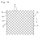
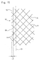
- a metal wire 70 (hereinafter referred to as "salvage 70") is welded along each end fringe 69 in a width direction (a direction indicated by an arrow) of a mesh 12 for a wired glass.
- the salvage 70 is welded to the mesh 12 at a position a predetermined distance L2 apart from an end 69 of the mesh 12 as illustrated in Fig. 15 by means of, for example, a spot welding, preferably a TIG welding.
- the predetermined distance L2 is preferably within a range of from 2 to 12 mm, more preferably from 3 to 8 mm, most preferably 6 mm.
- the salvage 70 is welded to the mesh 12 at positions excluding intersections 71. If the salvage 70 is welded to the mesh 12 at an intersection 71, there results a state of overlapping three wires, i.e., wires 11 and 11 of the mesh 12 and the salvage 70 and the thickness of the mesh 12 is thereby increased.
- a stainless steel wire is preferably employed as the salvage 70.
- Figs. 14 and 15 description has been made with respect to an example of applying salvages 70 to a mesh 12 having a rhombus meshwork.
- shape of meshwork is not limited to be rhombus.
- the meshwork in the Table is represented by the measured lengths of diagonal lines of a meshwork embedded in a glass sheet, and a diagonal line ratio means a ratio of the length of the two diagonal lines.
- the diagonal line ratio is preferably at least 0.95, more preferably at least 0.97. No.
- the wired glass 12 is cut along lines 73 apart inwardly from salvages 70. Since the deformation of the mesh 12 is prevented by welding the salvages 70 to the mesh 12, the external appearance of the wired glass can be improved.
- the diameter of the wires constituting the mesh is at least 0.30 mm and less than 0.45 mm, and the intersections of the wires are welded, whereby there is no risk that a relative position error is induced between the wires when the mesh is inserted in the ribbon glass, and in the same manner as a conventional wired glass employing a iron mesh, a good cutting property of the wired glass can be obtained.
- the contact portions of two wires are melted into each other so that the thickness of the mesh at the intersections becomes from 82 to 97% of the sum of the diameters of the two intercrossed wires, whereby there is little risk of separation of the welded portions and little risk of breaking of the wires.
- the wires can be continuously aligned and conveyed, whereby the relative position of the wires can securely be maintained.
- each of the grooves is a substantially V-shape
- the wires can be held with predetermined intervals.
- the wires can securely be fixed.
- the waving phenomenon can be suppressed, the flatness can be improved, and accordingly, the polishing amount of the surface of the wired glass can be reduced in the polishing step such as single-side continuous polishing method to improve the polishing efficiency.
- the mesh can be retrieved by a retrieving roll while a predetermined tension is applied to a mesh portion between upper and lower electrode assemblies and the retrieving roll.
- a flow of the mesh for a wired glass is corrected by a contact means so that the mesh for a wired glass is retrieved after it is passed through a predetermined position with respect to the retrieving roll.
- the contact means functions as a tensioner for absorbing a slack of the mesh for a wired glass, and it separates a first tension applied to the mesh at the upstream side of the contact means from the second tension applied to the mesh at the downstream side. Further, salvages are welded along both end fringes in the width direction of the mesh for a wired glass.
- the meshwork at a portion of the mesh can be prevented from occurring. Further, since loose winding of the mesh by the retrieving roll or uneven winding can be prevented, the mesh can be densely wound around the retrieving roll.
- the length of the mesh per roll can be made longer.
- the flatness of the glass sheet can be improved, whereby the amount of surface polishing of the wired glass can be reduced in a polishing step such as a single-side continuous polishing method or a double-side continuous polishing method, which can improve the polishing efficiency.
Landscapes
- Engineering & Computer Science (AREA)
- Mechanical Engineering (AREA)
- Chemical & Material Sciences (AREA)
- Materials Engineering (AREA)
- Organic Chemistry (AREA)
- Life Sciences & Earth Sciences (AREA)
- General Chemical & Material Sciences (AREA)
- Geochemistry & Mineralogy (AREA)
- Chemical Kinetics & Catalysis (AREA)
- Dispersion Chemistry (AREA)
- Ceramic Engineering (AREA)
- Wire Processing (AREA)
- Non-Insulated Conductors (AREA)
- Printing Plates And Materials Therefor (AREA)
- Superconductors And Manufacturing Methods Therefor (AREA)
- Insulated Conductors (AREA)
- Surface Treatment Of Glass Fibres Or Filaments (AREA)
- Braiding, Manufacturing Of Bobbin-Net Or Lace, And Manufacturing Of Nets By Knotting (AREA)
Abstract
Description
| Length of the rust proceeded (mm) | Cracks | |
| Product of the present invention | 2 to 3 | Not found |
| Conventional product 2 | 20 to 45 | Found on 5th day |
| Conventional product 1 | 200 to 450 | Found on 2nd day |
| 1 | 2 | 3 | 4 | Average | |
| Conventional product 1 | 0.19 | 0.20 | 0.33 | 0.45 | 0.29 |
| Product of the present invention | 0.13 | 0.15 | 0.10 | 0.05 | 0.09 |
| Mesh length (m) | Measured diameter (mm) | Calculated diameter (mm) | Mesh width (mm) |
| 50 | 218 | 210.8 | 2756 |
| 100 | 277 | 267.7 | 2756 |
| 150 | 330 | 320.9 | 2759 |
| 200 | 375 | 362.9 | 2757 |
| 250 | 413 | 400.4 | 2759 |
| 300 | 447 | 434.8 | 2759 |
| 350 | 487 | 466.6 | 2758 |
| 400 | 508 | 488.8 | 2759 |
| No. | Meshwork | |||
| R/L | X | Y | Diagonal line ratio | |
| 1 | R | 27.10 | 27.70 | 0.98 |
| L | 27.30 | 27.50 | 0.99 | |
| 2 | R | 22.20 | 21.50 | 0.97 |
| L | 22.30 | 21.55 | 0.97 | |
| 3 | R | 27.05 | 27.60 | 0.98 |
| L | 27.30 | 27.60 | 0.99 | |
| 4 | R | 27.05 | 27.60 | 0.98 |
| L | 27.40 | 27.70 | 0.99 | |
| 5 | R | 27.30 | 27.70 | 0.99 |
| L | 27.20 | 27.70 | 0.98 | |
| 6 | R | 27.00 | 27.65 | 0.97 |
| L | 27.20 | 27.60 | 0.98 | |
| 7 | R | 27.15 | 27.60 | 0.98 |
| L | 27.30 | 27.60 | 0.99 | |
| 8 | R | 27.30 | 27.70 | 0.99 |
| L | 27.20 | 27.60 | 0.98 | |
| 9 | R | 27.20 | 27.60 | 0.98 |
| L | 27.20 | 27.80 | 0.98 | |
| 10 | R | 27.15 | 27.65 | 0.98 |
| L | 27.20 | 27.70 | 0.98 |
Claims (17)
- A mesh for a wired glass, comprising stainless steel wires crossed one another, wherein the diameter of the wires is within a range of from 0.30 to 0.45 mm, and intersections of the wires are welded.
- The mesh for a wired glass according to Claim 1, wherein the thickness of each intersection is from 82 to 97% of the sum of diameters of two intercrossed wires.
- The mesh for a wired glass according to Claim 1 or 2, wherein the wires have an average linear expansion coefficient of at most 14×10-6/°C at a temperature of from 20 to 700°C and a tensile strength of at most 200 N/mm2 at 700°C.
- The mesh for a wired glass according to Claim 1, 2 or 3, wherein the wires consist essentially of from 74 to 83 % of Fe, from 0.2 to 8 % of Ni, from 16 to 25 % of Cr, from 0.5 to 2 % of Mn and from 0 to 3 % of Mo represented by mass percentage.
- A process for continuously producing a mesh for a wired glass, said mesh comprising stainless steel wires crossed one another, said process comprising:a step of crossing wires to obtain a wire-intercrossed product;a step of fitting said wire-intercrossed product to grooves of a rotatable cylindrical roll disposed perpendicularly to a direction of continuously producing the mesh, said grooves being formed with the same intervals as a mesh size of the mesh, in its outer periphery;a step of rotating said cylindrical roll around its own axis to continuously align and convey said wire-intercrossed product; anda step of welding intersections of the conveyed wire-intercrossed product.
- The process for producing a mesh for a wired glass, according to Claim 5, wherein the width of each groove at its bottom is from 1.1 to 2 times the diameter of the wires to be fitted, the width of the groove at its top is at least 2 times the diameter of said wires, and the width of the groove at its other portions is at least 1.1 times the diameter of said wires.
- The process for producing a mesh for a wired glass, according to Claim 5 or 6, wherein the welding of intersections in said wire-intercrossed product is carried out by means of a spot welding.
- The process for producing a mesh for a wired glass, according to Claim 5, 6 or 7, wherein the thickness of the welded intersections is from 82 to 97% of the sum of diameters of two intercrossed wires.
- The process for producing a mesh for a wired glass, according to Claim 5, 6, 7 or 8, wherein the diameter of the wires is from 0.30 to 0.45 mm.
- The process for producing a mesh for a wired glass, according to any one of Claims 5 to 9, wherein the wires have an average linear expansion coefficient of at most 14×10-6/°C at a temperature of from 20 to 700°C and a tensile strength of at most 200 N/mm2 at 700°C.
- The process for producing a mesh for a wired glass, according to any one of Claims 5 to 10, wherein the wires consist essentially of from 74 to 83 % of Fe, from 0.2 to 8 % of Ni, from 16 to 25 % of Cr, from 0.5 to 2 % of Mn and from 0 to 3 of Mo represented by mass percentage.
- The process for producing a mesh for a wired glass, according to any one of Claims 5 to 11, wherein a conveying speed V2 of the mesh having welded intersections is controlled to be equal to a conveying speed V1 of said wire-intercrossed product at said cylindrical roll.
- The process for producing a mesh for a wired glass, according to Claim 12, wherein the mesh having welded intersections is retrieved by a retrieving roll, and the rotation of said retrieving roll is controlled so that the retrieving length of the mesh from the time when said V1 is 0, is equal to the moving distance in a circumferential direction of the cylindrical roll from the circumferential position when V1 is 0.
- The process for producing a mesh for a wired glass, according to Claim 12, wherein the mesh having welded intersections is retrieved by a retrieving roll, and said mesh is pulled by the retrieving roll to an extent that V2 stays 0, when V1 is 0.
- The process for producing a mesh for a wired glass, according to Claim 12, wherein said mesh is applied with a constant tension.
- The process for producing a mesh for a wired glass, according to Claim 15, wherein the mesh is retrieved through a tensioner.
- The process for producing a mesh for a wired glass, according to Claim 16, wherein the tensioner has a vertically movable rotational roller in contact with the mesh, and the vertical position of the roller is controlled to suppress a slack of the mesh.
Applications Claiming Priority (3)
| Application Number | Priority Date | Filing Date | Title |
|---|---|---|---|
| JP2001300450 | 2001-09-28 | ||
| JP2001300450 | 2001-09-28 | ||
| PCT/JP2002/010084 WO2003028919A1 (en) | 2001-09-28 | 2002-09-27 | Wire for wired sheet glass and method of manufacturing the wire |
Publications (3)
| Publication Number | Publication Date |
|---|---|
| EP1430972A1 true EP1430972A1 (en) | 2004-06-23 |
| EP1430972A4 EP1430972A4 (en) | 2005-04-13 |
| EP1430972B1 EP1430972B1 (en) | 2007-04-11 |
Family
ID=19121026
Family Applications (1)
| Application Number | Title | Priority Date | Filing Date |
|---|---|---|---|
| EP02800273A Expired - Lifetime EP1430972B1 (en) | 2001-09-28 | 2002-09-27 | Wire for wired sheet glass and method of manufacturing the wire |
Country Status (5)
| Country | Link |
|---|---|
| EP (1) | EP1430972B1 (en) |
| JP (1) | JP4535726B2 (en) |
| AT (1) | ATE359137T1 (en) |
| DE (1) | DE60219493T2 (en) |
| WO (1) | WO2003028919A1 (en) |
Cited By (3)
| Publication number | Priority date | Publication date | Assignee | Title |
|---|---|---|---|---|
| CN103846373A (en) * | 2012-12-04 | 2014-06-11 | 兴化市戴南华龙金属工艺制品厂 | Stainless steel wire continuous and quick welding treatment process |
| CN105057867A (en) * | 2015-08-21 | 2015-11-18 | 南昌航空大学 | Cross resistance welding process for heterogeneous wires |
| WO2021050518A1 (en) * | 2019-09-10 | 2021-03-18 | Volm Companies, Inc. | Mesh network |
Families Citing this family (1)
| Publication number | Priority date | Publication date | Assignee | Title |
|---|---|---|---|---|
| KR101913687B1 (en) | 2017-05-31 | 2018-11-01 | 한윤석 | Equipment of manufacturing mesh for wired glass |
Family Cites Families (13)
| Publication number | Priority date | Publication date | Assignee | Title |
|---|---|---|---|---|
| GB263921A (en) * | 1925-10-03 | 1927-01-03 | Pilkington Brothers Ltd | Improvements in the production of welded wire fabric and apparatus therefor |
| US1842120A (en) * | 1927-10-03 | 1932-01-19 | Francis B Riley | Apparatus for the production of metallic fabrics |
| US1922270A (en) * | 1930-11-14 | 1933-08-15 | Welded Fabrics Corp | Fabric making |
| JPS52113358A (en) * | 1976-03-19 | 1977-09-22 | Nippon Sheet Glass Co Ltd | Method of making wire net suitable to nettreinforced glass in particular |
| JPS52138009A (en) * | 1976-05-14 | 1977-11-17 | Hitachi Metals Ltd | Alloy steel wire for reinforcing glass |
| JPS5924181B2 (en) * | 1978-05-10 | 1984-06-07 | 日本板硝子株式会社 | glass with metal wire |
| JPS62151237A (en) * | 1985-12-25 | 1987-07-06 | Sanwa Shoji Kk | Manufacturing device for corrugated wire for wire gauze |
| JPS6444234A (en) * | 1987-08-10 | 1989-02-16 | Deii Koriaa Jiyon | Production of wire mesh screen |
| JPH05177288A (en) * | 1991-12-26 | 1993-07-20 | Hitachi Cable Ltd | Method for manufacturing welded wire mesh |
| JPH0654436U (en) * | 1992-12-22 | 1994-07-26 | 松井金網工業株式会社 | Wire mesh processing equipment |
| JPH0717732A (en) * | 1993-07-02 | 1995-01-20 | Asahi Glass Co Ltd | Method for manufacturing integrated remelted glass |
| JP3175551B2 (en) * | 1995-09-19 | 2001-06-11 | 住友金属工業株式会社 | Manufacturing method of non-magnetic welded wire mesh |
| GB0008617D0 (en) * | 2000-04-10 | 2000-05-31 | Southfields Fabric Sys Ltd | Reinforced glass panel |
-
2002
- 2002-09-27 EP EP02800273A patent/EP1430972B1/en not_active Expired - Lifetime
- 2002-09-27 JP JP2003532226A patent/JP4535726B2/en not_active Expired - Fee Related
- 2002-09-27 AT AT02800273T patent/ATE359137T1/en not_active IP Right Cessation
- 2002-09-27 DE DE60219493T patent/DE60219493T2/en not_active Expired - Lifetime
- 2002-09-27 WO PCT/JP2002/010084 patent/WO2003028919A1/en not_active Ceased
Cited By (4)
| Publication number | Priority date | Publication date | Assignee | Title |
|---|---|---|---|---|
| CN103846373A (en) * | 2012-12-04 | 2014-06-11 | 兴化市戴南华龙金属工艺制品厂 | Stainless steel wire continuous and quick welding treatment process |
| CN105057867A (en) * | 2015-08-21 | 2015-11-18 | 南昌航空大学 | Cross resistance welding process for heterogeneous wires |
| WO2021050518A1 (en) * | 2019-09-10 | 2021-03-18 | Volm Companies, Inc. | Mesh network |
| US12251899B2 (en) | 2019-09-10 | 2025-03-18 | Volm Companies, Inc. | Mesh network |
Also Published As
| Publication number | Publication date |
|---|---|
| WO2003028919A1 (en) | 2003-04-10 |
| JPWO2003028919A1 (en) | 2005-01-13 |
| EP1430972B1 (en) | 2007-04-11 |
| DE60219493T2 (en) | 2007-12-20 |
| DE60219493D1 (en) | 2007-05-24 |
| ATE359137T1 (en) | 2007-05-15 |
| JP4535726B2 (en) | 2010-09-01 |
| EP1430972A4 (en) | 2005-04-13 |
Similar Documents
| Publication | Publication Date | Title |
|---|---|---|
| KR20130036151A (en) | Wire winding bobbin wire winding method and wire winding apparatus | |
| KR102149654B1 (en) | MOLTEN Al PLATED STEEL WIRE AS WELL AS STRANDED WIRE AND MANUFACTURING METHOD THEREFOR | |
| EP1430972B1 (en) | Wire for wired sheet glass and method of manufacturing the wire | |
| JPH0126763B2 (en) | ||
| JP2000167618A (en) | Method for drawing wire for wire saw and drawing device | |
| KR20140080367A (en) | System for adjusting direction of looper-car in stainless annealing pickling line | |
| EP1126935B1 (en) | Device to form spirals in a coiling machine for rolled stock | |
| JP2678839B2 (en) | Reuse device for wire once used for mash seam welding | |
| KR200489820Y1 (en) | Hooks for electrolytic pickling of wire coil | |
| JPS598449B2 (en) | Roller forming method for tubular bodies | |
| BE1032431B1 (en) | METHOD FOR MANUFACTURING A ROLLED OR DRAWN METAL WIRE AND THE METAL WIRE MANUFACTURED ACCORDING TO THE METHOD | |
| JPH0557522A (en) | Side trimming machine device | |
| CN224091268U (en) | Coiled material continuous processing winding and unwinding devices | |
| JP2004141908A (en) | Electric arc-welding solid wire without copper plating | |
| JPH04197515A (en) | Manufacture of welded steel pipe from plating steel strip and grinding device | |
| JP2989277B2 (en) | Holding device for rear end of steel sheet unwound from coil | |
| KR101373137B1 (en) | Sleeve for preventing end-mark of steel plate and steel plate winding apparatus having the same | |
| JP2006224119A (en) | Rolling method with cold tandem rolling mill | |
| JP3624787B2 (en) | Metal strip connection method by lap seam welding | |
| JP4696428B2 (en) | Continuous molten metal plating equipment for strips | |
| JPH0775731B2 (en) | Wire drawing method and apparatus using three rolls | |
| JP2006095557A (en) | Belt wrapper | |
| JPH04201052A (en) | Manufacturing method for steel pipe with plated steel strip as raw material and grinding device | |
| JPH11254019A (en) | Device and method for threading strip in rolling mill | |
| JPH06126328A (en) | Method and device for coiling slit metallic strip |
Legal Events
| Date | Code | Title | Description |
|---|---|---|---|
| PUAI | Public reference made under article 153(3) epc to a published international application that has entered the european phase |
Free format text: ORIGINAL CODE: 0009012 |
|
| 17P | Request for examination filed |
Effective date: 20030626 |
|
| AK | Designated contracting states |
Kind code of ref document: A1 Designated state(s): AT BE BG CH CY CZ DE DK EE ES FI FR GB GR IE IT LI LU MC NL PT SE SK TR |
|
| AX | Request for extension of the european patent |
Extension state: AL LT LV MK RO SI |
|
| A4 | Supplementary search report drawn up and despatched |
Effective date: 20050302 |
|
| RIC1 | Information provided on ipc code assigned before grant |
Ipc: 7C 03C 14/00 B Ipc: 7C 03B 13/12 B Ipc: 7B 21F 27/10 B Ipc: 7B 21F 27/22 B Ipc: 7B 21F 15/08 A Ipc: 7B 23K 11/00 B |
|
| GRAP | Despatch of communication of intention to grant a patent |
Free format text: ORIGINAL CODE: EPIDOSNIGR1 |
|
| GRAS | Grant fee paid |
Free format text: ORIGINAL CODE: EPIDOSNIGR3 |
|
| GRAA | (expected) grant |
Free format text: ORIGINAL CODE: 0009210 |
|
| AK | Designated contracting states |
Kind code of ref document: B1 Designated state(s): AT BE BG CH CY CZ DE DK EE ES FI FR GB GR IE IT LI LU MC NL PT SE SK TR |
|
| PG25 | Lapsed in a contracting state [announced via postgrant information from national office to epo] |
Ref country code: FI Free format text: LAPSE BECAUSE OF FAILURE TO SUBMIT A TRANSLATION OF THE DESCRIPTION OR TO PAY THE FEE WITHIN THE PRESCRIBED TIME-LIMIT Effective date: 20070411 Ref country code: CH Free format text: LAPSE BECAUSE OF FAILURE TO SUBMIT A TRANSLATION OF THE DESCRIPTION OR TO PAY THE FEE WITHIN THE PRESCRIBED TIME-LIMIT Effective date: 20070411 Ref country code: LI Free format text: LAPSE BECAUSE OF FAILURE TO SUBMIT A TRANSLATION OF THE DESCRIPTION OR TO PAY THE FEE WITHIN THE PRESCRIBED TIME-LIMIT Effective date: 20070411 |
|
| REG | Reference to a national code |
Ref country code: GB Ref legal event code: FG4D |
|
| REG | Reference to a national code |
Ref country code: CH Ref legal event code: EP |
|
| REG | Reference to a national code |
Ref country code: IE Ref legal event code: FG4D |
|
| REF | Corresponds to: |
Ref document number: 60219493 Country of ref document: DE Date of ref document: 20070524 Kind code of ref document: P |
|
| PG25 | Lapsed in a contracting state [announced via postgrant information from national office to epo] |
Ref country code: SE Free format text: LAPSE BECAUSE OF FAILURE TO SUBMIT A TRANSLATION OF THE DESCRIPTION OR TO PAY THE FEE WITHIN THE PRESCRIBED TIME-LIMIT Effective date: 20070711 |
|
| PG25 | Lapsed in a contracting state [announced via postgrant information from national office to epo] |
Ref country code: ES Free format text: LAPSE BECAUSE OF FAILURE TO SUBMIT A TRANSLATION OF THE DESCRIPTION OR TO PAY THE FEE WITHIN THE PRESCRIBED TIME-LIMIT Effective date: 20070722 |
|
| PG25 | Lapsed in a contracting state [announced via postgrant information from national office to epo] |
Ref country code: PT Free format text: LAPSE BECAUSE OF FAILURE TO SUBMIT A TRANSLATION OF THE DESCRIPTION OR TO PAY THE FEE WITHIN THE PRESCRIBED TIME-LIMIT Effective date: 20070911 |
|
| ET | Fr: translation filed | ||
| NLV1 | Nl: lapsed or annulled due to failure to fulfill the requirements of art. 29p and 29m of the patents act | ||
| REG | Reference to a national code |
Ref country code: CH Ref legal event code: PL |
|
| PG25 | Lapsed in a contracting state [announced via postgrant information from national office to epo] |
Ref country code: AT Free format text: LAPSE BECAUSE OF FAILURE TO SUBMIT A TRANSLATION OF THE DESCRIPTION OR TO PAY THE FEE WITHIN THE PRESCRIBED TIME-LIMIT Effective date: 20070411 |
|
| PG25 | Lapsed in a contracting state [announced via postgrant information from national office to epo] |
Ref country code: CZ Free format text: LAPSE BECAUSE OF FAILURE TO SUBMIT A TRANSLATION OF THE DESCRIPTION OR TO PAY THE FEE WITHIN THE PRESCRIBED TIME-LIMIT Effective date: 20070411 Ref country code: NL Free format text: LAPSE BECAUSE OF FAILURE TO SUBMIT A TRANSLATION OF THE DESCRIPTION OR TO PAY THE FEE WITHIN THE PRESCRIBED TIME-LIMIT Effective date: 20070411 Ref country code: DK Free format text: LAPSE BECAUSE OF FAILURE TO SUBMIT A TRANSLATION OF THE DESCRIPTION OR TO PAY THE FEE WITHIN THE PRESCRIBED TIME-LIMIT Effective date: 20070411 Ref country code: BG Free format text: LAPSE BECAUSE OF FAILURE TO SUBMIT A TRANSLATION OF THE DESCRIPTION OR TO PAY THE FEE WITHIN THE PRESCRIBED TIME-LIMIT Effective date: 20070711 |
|
| PLBE | No opposition filed within time limit |
Free format text: ORIGINAL CODE: 0009261 |
|
| STAA | Information on the status of an ep patent application or granted ep patent |
Free format text: STATUS: NO OPPOSITION FILED WITHIN TIME LIMIT |
|
| PG25 | Lapsed in a contracting state [announced via postgrant information from national office to epo] |
Ref country code: SK Free format text: LAPSE BECAUSE OF FAILURE TO SUBMIT A TRANSLATION OF THE DESCRIPTION OR TO PAY THE FEE WITHIN THE PRESCRIBED TIME-LIMIT Effective date: 20070411 |
|
| 26N | No opposition filed |
Effective date: 20080114 |
|
| PG25 | Lapsed in a contracting state [announced via postgrant information from national office to epo] |
Ref country code: GR Free format text: LAPSE BECAUSE OF FAILURE TO SUBMIT A TRANSLATION OF THE DESCRIPTION OR TO PAY THE FEE WITHIN THE PRESCRIBED TIME-LIMIT Effective date: 20070712 Ref country code: IT Free format text: LAPSE BECAUSE OF FAILURE TO SUBMIT A TRANSLATION OF THE DESCRIPTION OR TO PAY THE FEE WITHIN THE PRESCRIBED TIME-LIMIT Effective date: 20070411 Ref country code: MC Free format text: LAPSE BECAUSE OF NON-PAYMENT OF DUE FEES Effective date: 20070930 |
|
| PG25 | Lapsed in a contracting state [announced via postgrant information from national office to epo] |
Ref country code: IE Free format text: LAPSE BECAUSE OF NON-PAYMENT OF DUE FEES Effective date: 20070927 |
|
| PG25 | Lapsed in a contracting state [announced via postgrant information from national office to epo] |
Ref country code: EE Free format text: LAPSE BECAUSE OF FAILURE TO SUBMIT A TRANSLATION OF THE DESCRIPTION OR TO PAY THE FEE WITHIN THE PRESCRIBED TIME-LIMIT Effective date: 20070411 |
|
| PG25 | Lapsed in a contracting state [announced via postgrant information from national office to epo] |
Ref country code: CY Free format text: LAPSE BECAUSE OF FAILURE TO SUBMIT A TRANSLATION OF THE DESCRIPTION OR TO PAY THE FEE WITHIN THE PRESCRIBED TIME-LIMIT Effective date: 20070411 |
|
| PG25 | Lapsed in a contracting state [announced via postgrant information from national office to epo] |
Ref country code: LU Free format text: LAPSE BECAUSE OF NON-PAYMENT OF DUE FEES Effective date: 20070927 |
|
| PG25 | Lapsed in a contracting state [announced via postgrant information from national office to epo] |
Ref country code: TR Free format text: LAPSE BECAUSE OF FAILURE TO SUBMIT A TRANSLATION OF THE DESCRIPTION OR TO PAY THE FEE WITHIN THE PRESCRIBED TIME-LIMIT Effective date: 20070411 |
|
| PGFP | Annual fee paid to national office [announced via postgrant information from national office to epo] |
Ref country code: DE Payment date: 20130925 Year of fee payment: 12 |
|
| PGFP | Annual fee paid to national office [announced via postgrant information from national office to epo] |
Ref country code: FR Payment date: 20130910 Year of fee payment: 12 Ref country code: GB Payment date: 20130925 Year of fee payment: 12 |
|
| PGFP | Annual fee paid to national office [announced via postgrant information from national office to epo] |
Ref country code: BE Payment date: 20130912 Year of fee payment: 12 |
|
| REG | Reference to a national code |
Ref country code: DE Ref legal event code: R119 Ref document number: 60219493 Country of ref document: DE |
|
| GBPC | Gb: european patent ceased through non-payment of renewal fee |
Effective date: 20140927 |
|
| REG | Reference to a national code |
Ref country code: DE Ref legal event code: R119 Ref document number: 60219493 Country of ref document: DE Effective date: 20150401 |
|
| REG | Reference to a national code |
Ref country code: FR Ref legal event code: ST Effective date: 20150529 |
|
| PG25 | Lapsed in a contracting state [announced via postgrant information from national office to epo] |
Ref country code: BE Free format text: LAPSE BECAUSE OF NON-PAYMENT OF DUE FEES Effective date: 20140930 |
|
| PG25 | Lapsed in a contracting state [announced via postgrant information from national office to epo] |
Ref country code: GB Free format text: LAPSE BECAUSE OF NON-PAYMENT OF DUE FEES Effective date: 20140927 Ref country code: DE Free format text: LAPSE BECAUSE OF NON-PAYMENT OF DUE FEES Effective date: 20150401 |
|
| PG25 | Lapsed in a contracting state [announced via postgrant information from national office to epo] |
Ref country code: FR Free format text: LAPSE BECAUSE OF NON-PAYMENT OF DUE FEES Effective date: 20140930 |