EP1430964A2 - Drawing of steel wire - Google Patents
Drawing of steel wire Download PDFInfo
- Publication number
- EP1430964A2 EP1430964A2 EP03104629A EP03104629A EP1430964A2 EP 1430964 A2 EP1430964 A2 EP 1430964A2 EP 03104629 A EP03104629 A EP 03104629A EP 03104629 A EP03104629 A EP 03104629A EP 1430964 A2 EP1430964 A2 EP 1430964A2
- Authority
- EP
- European Patent Office
- Prior art keywords
- wire
- diameter
- strain
- die
- reducing
- Prior art date
- Legal status (The legal status is an assumption and is not a legal conclusion. Google has not performed a legal analysis and makes no representation as to the accuracy of the status listed.)
- Granted
Links
Images


Classifications
-
- B—PERFORMING OPERATIONS; TRANSPORTING
- B21—MECHANICAL METAL-WORKING WITHOUT ESSENTIALLY REMOVING MATERIAL; PUNCHING METAL
- B21C—MANUFACTURE OF METAL SHEETS, WIRE, RODS, TUBES, PROFILES OR LIKE SEMI-MANUFACTURED PRODUCTS OTHERWISE THAN BY ROLLING; AUXILIARY OPERATIONS USED IN CONNECTION WITH METAL-WORKING WITHOUT ESSENTIALLY REMOVING MATERIAL
- B21C1/00—Manufacture of metal sheets, wire, rods, tubes or like semi-manufactured products by drawing
- B21C1/02—Drawing metal wire or like flexible metallic material by drawing machines or apparatus in which the drawing action is effected by drums
- B21C1/04—Drawing metal wire or like flexible metallic material by drawing machines or apparatus in which the drawing action is effected by drums with two or more dies operating in series
-
- B—PERFORMING OPERATIONS; TRANSPORTING
- B21—MECHANICAL METAL-WORKING WITHOUT ESSENTIALLY REMOVING MATERIAL; PUNCHING METAL
- B21C—MANUFACTURE OF METAL SHEETS, WIRE, RODS, TUBES, PROFILES OR LIKE SEMI-MANUFACTURED PRODUCTS OTHERWISE THAN BY ROLLING; AUXILIARY OPERATIONS USED IN CONNECTION WITH METAL-WORKING WITHOUT ESSENTIALLY REMOVING MATERIAL
- B21C1/00—Manufacture of metal sheets, wire, rods, tubes or like semi-manufactured products by drawing
-
- C—CHEMISTRY; METALLURGY
- C21—METALLURGY OF IRON
- C21D—MODIFYING THE PHYSICAL STRUCTURE OF FERROUS METALS; GENERAL DEVICES FOR HEAT TREATMENT OF FERROUS OR NON-FERROUS METALS OR ALLOYS; MAKING METAL MALLEABLE, e.g. BY DECARBURISATION OR TEMPERING
- C21D8/00—Modifying the physical properties of ferrous metals or ferrous alloys by deformation combined with, or followed by, heat treatment
- C21D8/06—Modifying the physical properties of ferrous metals or ferrous alloys by deformation combined with, or followed by, heat treatment during manufacturing of rods or wires
Definitions
- the present invention is directed to methods of drawing a steel wire. Specifically, the wire is subjected to a non-linear method of drawing a steel wire, resulting in an increased strength of the wire.
- Transformation of the steel alloy into a filament suitable for reinforcing rubber articles involves multiple processing stages, including rough drawing, patenting, brass plating and fine drawing.
- the selected process to achieve a steel wire with defined characteristics can include many variations on those processing stages, including repeating the different stages.
- rough drawing i.e. dry drawing of a rod to an intermediate wire diameter
- a taper draft larger diameter reductions are made at the beginning die positions while the wire is ductile, i.e. a relatively high drawing strain is used, and at the final die position, smaller reductions are made, i.e. a relatively lower drawing strain is employed, when the wire has a higher strength due to strain hardening.
- Conventional linear taper drafts are designed to achieve equal work done at the first and the last die position, and the dependence of the strain on the die position represents a straight line. In this approach, only original wire strength and the final strength are taken into account, while the wire strength at the intermediate die positions is not considered. Thus the amount of drawing strain employed through the die positions is reduced by a constant amount as the wire diameter is reduced.
- FIG. 3 illustrates the drawing strain and die position relationship for a linear taper draft. Such linear tapered drawing is only used during rough drawing.
- Another known method of drafting is an even area reduction draft.
- even area reduction the drawing strain applied at each successive die in the die path is the same as the diameter of the wire is slowly reduced. Even area reduction is employed during both rough and fine drawing.
- the invention provides solutions for designing optimized die drawing drafts to achieve increased efficiency of the drawing process and high strength wires with improved torsion characteristics.
- the invention takes into account the actual wire strength at the intermediate die positions while drawing a wire to a final desired diameter.
- Disclosed is a process for drawing of a wire to smaller diameter, either an intermediate bright wire size or a final desired diameter, according to the independent claims.
- the processes of drawing are referred to as non-linear tapered draft.
- the drawn wire has a final desired diameter of 0.1 to 0.4 mm.
- a diameter range is exemplary for a final diameter after both a rough draw, patenting, and a final drawing.
- the final desired diameter is 2.5 to 1.0 mm. Both of these diameters are preferably for an initial wire diameter is 4.0 to 5.5 mm and such wires are most useful in tire manufacturing, automotive part manufacturing, and conveyors belts.
- the wire may be drawn again after the non-linear tapered draft; thus the non-linear tapered draft occurs during the rough draw.
- the additional drawing following the rough draw may be a skin pass wherein the diameter is reduced by less than 4% or it may be a desired fine draw.
- the draft technique used may be selected from among the following drawing methods: gradually reducing the drawing strain at each successive die (i.e., non-linear tapered draft); reducing the drawing strain at each successive die by a constant amount (linear tapered draft); applying a constant drawing strain at each successive die (even area reduction); or a combination of any of the above.
- Applicants teach employing a skin pass following the rough drawing of the wire from an initial diameter to a bright wire diameter.
- the type of draft employed during the rough drawing is irrelevant and may be the non-linear tapered draft, the linear tapered draft, even area reduction, or even a combination of these types.
- FIG. 1 is a graph showing the relationship between the tensile strength and the drawing strain of wires.
- the upper curve represents steel with a carbon content of 0.96%
- the lower curve represents steel with a carbon content of 0.77%.
- the tensile strength increases as the drawing strain is increased.
- a typical wire forming process includes two distinct drawing stages and typically starts with a rough drawing and terminates with a fine drawing.
- rough drawing usually accomplished using a dry lubricant
- the original rod diameter is reduced to an intermediate wire diameter, also known as the bright wire diameter.
- the wire is typically heat treated (i.e. patented) to restore drawability and then subjected to fine drawing.
- fine drawing wire is drawn by using a wet lubricant to its final diameter.
- wire drawing dies It is desirable to use die drafts reducing dynamic strain aging and surface residual stresses negatively impacting wire properties and excessive die wear.
- the present invention provides solutions for achieving these desired effects during the different drawings by using drawings differing from those previously known and employed. Disclosed are combinations of different drafts used at different times, skin passes, non-linear tapered drafts, and mixed taper-even area reduction drafts.
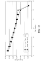
- the drawing strain in a non-linear tapered draft is calculated based upon the actual steel wire strength during each phase of the wire drawing.
- the reduction in diameter is greater when the steel is soft and has a relatively high ductility, and the drawing strain to which the wire is subjected is greater, and the reduction in diameter at the final stages of the drawing process is relatively smaller than at the beginning of the drawing process, that is - the drawing strain to which the wire is subject is relatively less.
- the initial and final steps may be similar to linear taper draft, the distinction is the change in drawing strain during the intermediate successive dies.
- FIG. 2 by basing the drawing strain on the actual wire strength, the process results in a non-linear drawing process, as defined by the drawing strain versus the die positions.
- the drawing strain to which the wire is subjected is gradually reduced at successive dies; that is, the drawing strain at each successive die is reduced from the previous die by a non-constant amount.
- the actual wire strength must be first determined prior to setting up the dies for the draft.
- the coefficient ⁇ is typically in the range of 0.2 to 0.5 for high carbon steel.
- an initial wire diameter ranges from 4.0 to 6.0 mm and is reduced to an intermediate diameter of 2.5 to 1.0 mm.
- the non-linear tapered draft reduces wire overheating thereby eliminating strain aging during wire drawing and reducing die wear. This process also improves wire drawability and reduces the probability of micro-crack formations in the bright wire.
- the non-linear tapered draft may also be employed during the fine drawing of the wire, following patenting of the wire, instead of the conventional even area reduction drawing.
- the wire Prior to the fine draw, the wire may be treated for corrosion resistance and to improve the drawability and adhesion characteristics of the wire.
- the wire may be coated with a thin layer of brass or brass alloys to improve adhesion of the steel wire to elastomers.
- brass is the coating of choice and the coating weight should be sufficient to remain on the filament after the drawing operation, also the brass should be predominately alpha brass in order to facilitate the drawability.
- the non-linear tapered draft can also be used in combination with other conventional drafts to achieve either rough drawing or fine drawing.
- FIG. 3 graphs the use of the non-linear tapered draft in combination with an even area tapered draft during fine drawing of a wire, followed by a skin pass, to reduce the intermediate diameter wire from 1.6 mm to a final 0.2 mm diameter. This draft is compared to a constant even area reduction draft. In fine drawing, the even area reduction draft is the conventional draft process employed.
- the final wire diameter typical for use in tire manufacturing, ranges from 0.1 to 0.4 mm.
- the non-linear tapered drawing is accomplished using the dies having an 8° approach angle, as understood by those skilled in the art.
- the drawing can also be achieved with different approach angles, including known 10° or 12° dies.
- the disclosed drawing methods are applicable in manufacturing wires having any strength, but are most applicable for manufacturing high tensile strength wires with strengths preferably greater than 4000 MPa.
- non-linear tapered draft improves wire processability, eliminates dynamic aging, avoids the need for an intermediate patenting process as used in conventional wire formation, thereby increasing processing efficiency and reducing wire manufacturing time. Additionally, since the drawing is optimized, the number of dies used in the fine drawing stage can be reduced yielding cost savings and improved process efficiency.
- linear tapered draft As previously discussed, during a linear tapered draft, the amount of the drawing strain applied to the wire during drawing is reduced by a constant amount between successive dies. This method has conventionally only been employed during rough drawing of the wire from an initial wire diameter to an intermediate bright wire diameter. Applicants have determined that linear tapered draft can also successively be used during fine drawing of the wire. The use of linear tapered draft during fine drawing reduces the number of dies employed, reducing manufacturing costs while varying the amount of drawing strain and the resulting strength characteristics of the wire. The use of a non-even area drafting technique used during fine drawing, even if used in combination with an even area draft, enables the engineer to achieve a more specific strength in the finished wire and control the overall finished characteristics of the wire.
- a skin pass is a small reduction of the wire diameter, not more than 4% of the initial diameter, occurring either at the final die in a set of dies during a draw or during a separate step following drawing. Conventionally, a skin pass is employed only following fine drawing of the wire. The inventors have determined that skin passes may be employed whenever control of torsion properties is essential, and skin passes may be employed also during rough drawing of the wire regardless of the type of drawing employed.
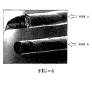
- FIG. 4 illustrates two wires subjected to a torsion test.
- Wire A was drawn using a conventional linear taper draft without a skin pass with the total drawing strain of 3.64.
- Wire B of the same composition, was drawn using a linear taper draft followed by a 4% reduction skin pass, resulting in the total drawing strain of 3.68. Both wires were then subjected to a torsion test.
- the wire drawn without a skin pass shows delamination, i.e. axial cracking splitting the wire along its axis.
- the wire drawn with a skin pass did not delaminate even when the total drawing strain was higher as compared with the wire drawn without skin pass.
- the use of the skin pass reduces wire delamination thereby improving torsion characteristics of the wire.
- the resulting wires formed using any of the disclosed combinations of drawing methods and skin passes may be used in various products such as tires, hoses, conveyor belts, power transmission products, and other products reinforced by steel wire.
- the wire has particular application as filaments that are stranded together and then cabled to form tire cords.
- the cords depending on the size, are useful in tread reinforcing plies such as belts, underlays, or overlays, and carcass plies.
- the wire may also be used to in forming tire beads.
- the wire, at the largest diameter, may be useful as a monofilament reinforcement in various parts of a tire.
Landscapes
- Engineering & Computer Science (AREA)
- Chemical & Material Sciences (AREA)
- Mechanical Engineering (AREA)
- Manufacturing & Machinery (AREA)
- Physics & Mathematics (AREA)
- Thermal Sciences (AREA)
- Crystallography & Structural Chemistry (AREA)
- Materials Engineering (AREA)
- Metallurgy (AREA)
- Organic Chemistry (AREA)
- Metal Extraction Processes (AREA)
- Ropes Or Cables (AREA)
Abstract
Description
Claims (10)
- A process for drawing a wire to a desired diameter, comprising the following steps:a) selecting a wire having an initial diameter;b) drawing the wire through a series of wire dies to reduce the wire diameter to a desired diameter wherein the drawing strain at each successive die is gradually reduced from the previous die by a non-constant amount.
- The process according to claim 1 comprising the additional step of drawing the wire to further reduce the wire diameter.
- The process according to claim 1 or 2 comprising the additional step of reducing the desired diameter of the wire by less than 4%.
- The process according to claim 3 comprising the additional step of again reducing the wire diameter by less than 4%.
- The process according to claim 2, 3 or 4, wherein the further drawing is selected from among the following drawing methods: gradually reducing the drawing strain at each successive die; reducing the drawing strain at each successive die by a constant amount; applying a constant drawing strain at each successive die; or a combination of any of the above.
- The process according to at least one of the previous claims, wherein prior to step a), the actual steel wire strength is calculated and used to determine the drawing strain to be employed at each successive die.
- The process according to at least one of the previous claims, wherein the initial wire diameter is 4.0 to 5.5 mm, and wherein the wire is drawn to a desired diameter of either 2.5 mm to 1.0 mm or 0.4 mm to 0.1 mm.
- A process for drawing a wire to desired diameter, comprising the following steps:a) selecting a wire having an initial diameter;b) drawing the wire through a series of wire dies to reduce the wire diameter to a desired intermediate diameter;c) reducing the diameter of the wire by an amount less than 4% of the intermediate diameter; andd) drawing the wire through a series of wire dies to reduce the wire diameter to a desired final diameter.
- The process according to claim 8, wherein the drawing of step b) is accomplished by selecting one of the following drawing methods: gradually reducing the drawing strain at each successive die; reducing the drawing strain at each successive die by a constant amount; applying a constant drawing strain at each successive die; or a combination of any of the above.
- A process for drawing a wire to desired diameter, comprising the following steps:a) selecting a wire having an initial diameter;b) drawing the wire through a series of wire dies to reduce the wire diameter to a desired intermediate diameter;c) heat treating the wire;d) drawing the wire through a series of wire dies to reduce the wire diameter to a desired final diameter wherein the drawing strain at each successive die is reduced by a constant amount.
Priority Applications (1)
| Application Number | Priority Date | Filing Date | Title |
|---|---|---|---|
| EP06112953A EP1688191A3 (en) | 2002-12-18 | 2003-12-10 | Drawing of steel wire |
Applications Claiming Priority (2)
| Application Number | Priority Date | Filing Date | Title |
|---|---|---|---|
| US322997 | 2002-12-18 | ||
| US10/322,997 US6715331B1 (en) | 2002-12-18 | 2002-12-18 | Drawing of steel wire |
Related Child Applications (1)
| Application Number | Title | Priority Date | Filing Date |
|---|---|---|---|
| EP06112953A Division EP1688191A3 (en) | 2002-12-18 | 2003-12-10 | Drawing of steel wire |
Publications (3)
| Publication Number | Publication Date |
|---|---|
| EP1430964A2 true EP1430964A2 (en) | 2004-06-23 |
| EP1430964A3 EP1430964A3 (en) | 2004-11-24 |
| EP1430964B1 EP1430964B1 (en) | 2006-11-22 |
Family
ID=32030482
Family Applications (2)
| Application Number | Title | Priority Date | Filing Date |
|---|---|---|---|
| EP03104629A Expired - Lifetime EP1430964B1 (en) | 2002-12-18 | 2003-12-10 | Drawing of steel wire |
| EP06112953A Ceased EP1688191A3 (en) | 2002-12-18 | 2003-12-10 | Drawing of steel wire |
Family Applications After (1)
| Application Number | Title | Priority Date | Filing Date |
|---|---|---|---|
| EP06112953A Ceased EP1688191A3 (en) | 2002-12-18 | 2003-12-10 | Drawing of steel wire |
Country Status (4)
| Country | Link |
|---|---|
| US (1) | US6715331B1 (en) |
| EP (2) | EP1430964B1 (en) |
| BR (1) | BR0306018A (en) |
| DE (1) | DE60309820T2 (en) |
Families Citing this family (9)
| Publication number | Priority date | Publication date | Assignee | Title |
|---|---|---|---|---|
| DE10339867B4 (en) * | 2003-08-25 | 2007-12-27 | Leibniz-Institut Für Festkörper- Und Werkstoffforschung Dresden E.V. | Method for the production of metallic flat wires or tapes with cube texture |
| US7188503B2 (en) * | 2004-10-29 | 2007-03-13 | The Goodyear Tire + Rubber Company | Fine wire drawing machine |
| JP2008069409A (en) * | 2006-09-14 | 2008-03-27 | Bridgestone Corp | High strength high carbon steel wire and method for producing the same |
| US8256085B2 (en) * | 2008-11-17 | 2012-09-04 | Lincoln Global, Inc. | System and method for classifying wire |
| CN102341194A (en) * | 2009-03-02 | 2012-02-01 | 株式会社普利司通 | Method of producing steel wire |
| ITMI20131926A1 (en) * | 2013-11-20 | 2015-05-21 | Danieli Off Mecc | TUBE DRAWING MACHINE |
| RU2661161C1 (en) * | 2017-04-17 | 2018-07-12 | федеральное государственное бюджетное образовательное учреждение высшего образования "Пермский национальный исследовательский политехнический университет" | Method of production of axisymmetric bar and wire metal products of increased accuracy |
| JP6520985B2 (en) * | 2017-05-02 | 2019-05-29 | 横浜ゴム株式会社 | Bead ring and method of manufacturing the same |
| CN111482476A (en) * | 2019-01-25 | 2020-08-04 | 江阴祥瑞不锈钢精线有限公司 | Stainless steel wire drawing method |
Family Cites Families (30)
| Publication number | Priority date | Publication date | Assignee | Title |
|---|---|---|---|---|
| GB748357A (en) * | 1953-06-01 | 1956-05-02 | Somerset Wire Company Ltd | Improvements in the manufacture of wire and the like |
| US3486361A (en) * | 1967-07-20 | 1969-12-30 | Babcock & Wilcox Co | Strengthening of elongated metal sections |
| GB1477377A (en) | 1973-12-17 | 1977-06-22 | Kobe Steel Ltd | Steel rod and method of producing steel rod |
| US4842818A (en) | 1980-03-17 | 1989-06-27 | Daido Tokushuko Kabushiki Kaisha | Method for manufacturing tapered rods |
| GB8332395D0 (en) | 1983-12-05 | 1984-01-11 | Bekaert Sa Nv | Steel wires |
| JPS62170460A (en) | 1986-01-21 | 1987-07-27 | Honda Motor Co Ltd | High strength valve spring steel and its manufacture |
| JP2735647B2 (en) | 1988-12-28 | 1998-04-02 | 新日本製鐵株式会社 | High strength and high ductility steel wire and method for producing high strength and high ductility extra fine steel wire |
| WO1992008817A1 (en) | 1990-11-19 | 1992-05-29 | Nippon Steel Corporation | High-strength ultrafine steel wire with excellent workability in stranding, and process and apparatus for producing the same |
| DE69116843T2 (en) | 1990-12-28 | 1996-08-14 | Kobe Steel Ltd | Tire cord made of steel wires with high strength and high toughness, and method of manufacturing the same |
| JP2627373B2 (en) | 1991-07-08 | 1997-07-02 | 金井 宏之 | High strength extra fine metal wire |
| US5609013A (en) | 1992-12-10 | 1997-03-11 | Bridgestone Bekaert Steel Cord Co., Ltd. | Steel cords for the reinforcement of rubber articles |
| US5603208A (en) | 1992-12-10 | 1997-02-18 | Bridgestone Bekaert Steel Cord Co., Ltd. | Composite rubber bodies using steel cords for the reinforcement of rubber articles |
| CA2098160A1 (en) | 1993-04-12 | 1994-10-13 | Charles N.A. Tonteling | Process for producing patented steel wire |
| FR2711149A1 (en) | 1993-10-15 | 1995-04-21 | Michelin & Cie | Stainless steel wire for tire casing carcass. |
| JPH07305285A (en) * | 1994-05-09 | 1995-11-21 | Bridgestone Metarufua Kk | Manufacturing method of steel cord wire for reinforcing rubber article |
| JPH07308707A (en) * | 1994-05-17 | 1995-11-28 | Nippon Steel Corp | Method for manufacturing brass-plated steel wire |
| US5535612A (en) | 1994-10-21 | 1996-07-16 | The Goodyear Tire & Rubber Company | Method and apparatus for drawing wire through a plurality of standard dies at the die positions |
| US5956935A (en) * | 1995-03-17 | 1999-09-28 | Tokyo Rope Manufacturing Co., Ltd. | High tensile steel filament member for rubber product reinforcement |
| JP2772627B2 (en) | 1995-05-16 | 1998-07-02 | 東京製綱株式会社 | Ultra-high strength steel wire and steel cord for rubber reinforcement |
| US5806296A (en) | 1995-05-26 | 1998-09-15 | Bridgestone Metalpha Corporation | Corrosion resistant spiral steel filament and steel cord made therefrom |
| JPH0999312A (en) * | 1995-10-05 | 1997-04-15 | Nippon Steel Corp | Method for producing high-strength ultrafine steel wire with excellent ductility |
| US6099797A (en) | 1996-09-04 | 2000-08-08 | The Goodyear Tire & Rubber Company | Steel tire cord with high tensile strength |
| CA2209469A1 (en) | 1996-09-16 | 1998-03-16 | The Goodyear Tire & Rubber Company | Process for producing patented steel wire |
| JP3844267B2 (en) * | 1997-05-21 | 2006-11-08 | 株式会社ブリヂストン | Steel wire manufacturing method |
| JPH1133617A (en) * | 1997-07-09 | 1999-02-09 | Tokyo Seiko Co Ltd | Manufacturing method of tough steel wire for rubber reinforcement and tough steel cord |
| JP4392868B2 (en) * | 1998-02-24 | 2010-01-06 | 株式会社ブリヂストン | Multi-stage slip type wet wire drawing method |
| FR2778188B1 (en) | 1998-04-29 | 2000-06-02 | Ugine Savoie Sa | STAINLESS STEEL FOR MAKING DRAWN WIRE IN PARTICULAR TIRE REINFORCEMENT WIRE AND METHOD FOR MAKING THE SAME WIRE |
| EP1038985A4 (en) | 1998-07-17 | 2003-04-02 | Sumitomo Metal Ind | PURIFIED STEEL |
| JP3409055B2 (en) * | 1998-10-16 | 2003-05-19 | 浦項綜合製鐵株式会社 | Wire for high-strength steel wire with excellent drawability and method for producing high-strength steel wire |
| JP3435112B2 (en) | 1999-04-06 | 2003-08-11 | 株式会社神戸製鋼所 | High carbon steel wire excellent in longitudinal crack resistance, steel material for high carbon steel wire, and manufacturing method thereof |
-
2002
- 2002-12-18 US US10/322,997 patent/US6715331B1/en not_active Expired - Lifetime
-
2003
- 2003-12-10 EP EP03104629A patent/EP1430964B1/en not_active Expired - Lifetime
- 2003-12-10 EP EP06112953A patent/EP1688191A3/en not_active Ceased
- 2003-12-10 DE DE60309820T patent/DE60309820T2/en not_active Expired - Fee Related
- 2003-12-11 BR BR0306018-7A patent/BR0306018A/en not_active Application Discontinuation
Also Published As
| Publication number | Publication date |
|---|---|
| EP1430964B1 (en) | 2006-11-22 |
| DE60309820D1 (en) | 2007-01-04 |
| EP1688191A3 (en) | 2006-11-02 |
| DE60309820T2 (en) | 2007-10-11 |
| BR0306018A (en) | 2004-08-31 |
| EP1430964A3 (en) | 2004-11-24 |
| EP1688191A2 (en) | 2006-08-09 |
| US6715331B1 (en) | 2004-04-06 |
Similar Documents
| Publication | Publication Date | Title |
|---|---|---|
| US4854032A (en) | Method of manufacturing a steel wire with high tensile strength | |
| CN1096367C (en) | Tyre with peripheral steel cable for fixing tyre body and technology for treating such steel cable | |
| US5806296A (en) | Corrosion resistant spiral steel filament and steel cord made therefrom | |
| AU655326B2 (en) | Method and apparatus for wire drawing | |
| US6715331B1 (en) | Drawing of steel wire | |
| WO2020173759A1 (en) | A steel cord for rubber reinforcement | |
| US6203932B1 (en) | Steel wire for reinforcement of rubber articles, method of manufacturing the same, and steel cord using the same | |
| US6823706B1 (en) | Steel wire and method of manufacturing the same | |
| KR100916917B1 (en) | Single wire steel cord | |
| EP3710286B1 (en) | A steel cord for rubber reinforcement | |
| JPH08218282A (en) | Ultra high strength steel wire and steel cord for rubber reinforcement | |
| EP4263933B1 (en) | A steel cord for rubber reinforcement | |
| JPH06184965A (en) | Steel cord | |
| EP0611669A1 (en) | High-strength bead wire | |
| US5609013A (en) | Steel cords for the reinforcement of rubber articles | |
| EP1420965B1 (en) | Steel cord structure in heavy duty tires | |
| JPH08226085A (en) | Ultra high strength steel cord and radial tire using the same | |
| JP3299857B2 (en) | High-strength extra-fine steel wire with excellent fatigue properties and method for producing the same | |
| WO2022048822A1 (en) | A steel cord for rubber reinforcement | |
| WO2024207219A1 (en) | A high elongation steel cord for rubber reinforcement | |
| CN111482476A (en) | Stainless steel wire drawing method | |
| WO2025252708A1 (en) | Steel cord having five steel filaments for rubber reinforcement | |
| JP2989860B2 (en) | Manufacturing method of rubber reinforcement | |
| WO2025252487A1 (en) | Steel cord having six steel filaments for rubber reinforcement | |
| JP2004034102A (en) | Steel wire manufacturing method, steel cord for reinforcement of rubber, and steel wire |
Legal Events
| Date | Code | Title | Description |
|---|---|---|---|
| PUAI | Public reference made under article 153(3) epc to a published international application that has entered the european phase |
Free format text: ORIGINAL CODE: 0009012 |
|
| AK | Designated contracting states |
Kind code of ref document: A2 Designated state(s): AT BE BG CH CY CZ DE DK EE ES FI FR GB GR HU IE IT LI LU MC NL PT RO SE SI SK TR |
|
| AX | Request for extension of the european patent |
Extension state: AL LT LV MK |
|
| PUAL | Search report despatched |
Free format text: ORIGINAL CODE: 0009013 |
|
| RIC1 | Information provided on ipc code assigned before grant |
Ipc: 7B 21C 1/04 B Ipc: 7C 21D 8/06 B Ipc: 7B 21C 1/00 A |
|
| AK | Designated contracting states |
Kind code of ref document: A3 Designated state(s): AT BE BG CH CY CZ DE DK EE ES FI FR GB GR HU IE IT LI LU MC NL PT RO SE SI SK TR |
|
| AX | Request for extension of the european patent |
Extension state: AL LT LV MK |
|
| 17P | Request for examination filed |
Effective date: 20050524 |
|
| AKX | Designation fees paid |
Designated state(s): BE DE ES FR GB IT |
|
| GRAP | Despatch of communication of intention to grant a patent |
Free format text: ORIGINAL CODE: EPIDOSNIGR1 |
|
| GRAS | Grant fee paid |
Free format text: ORIGINAL CODE: EPIDOSNIGR3 |
|
| GRAA | (expected) grant |
Free format text: ORIGINAL CODE: 0009210 |
|
| AK | Designated contracting states |
Kind code of ref document: B1 Designated state(s): BE DE ES FR GB IT |
|
| REG | Reference to a national code |
Ref country code: GB Ref legal event code: FG4D |
|
| REF | Corresponds to: |
Ref document number: 60309820 Country of ref document: DE Date of ref document: 20070104 Kind code of ref document: P |
|
| PG25 | Lapsed in a contracting state [announced via postgrant information from national office to epo] |
Ref country code: ES Free format text: LAPSE BECAUSE OF FAILURE TO SUBMIT A TRANSLATION OF THE DESCRIPTION OR TO PAY THE FEE WITHIN THE PRESCRIBED TIME-LIMIT Effective date: 20070305 |
|
| ET | Fr: translation filed | ||
| PLBE | No opposition filed within time limit |
Free format text: ORIGINAL CODE: 0009261 |
|
| STAA | Information on the status of an ep patent application or granted ep patent |
Free format text: STATUS: NO OPPOSITION FILED WITHIN TIME LIMIT |
|
| 26N | No opposition filed |
Effective date: 20070823 |
|
| PGFP | Annual fee paid to national office [announced via postgrant information from national office to epo] |
Ref country code: IT Payment date: 20071215 Year of fee payment: 5 |
|
| PGFP | Annual fee paid to national office [announced via postgrant information from national office to epo] |
Ref country code: BE Payment date: 20071221 Year of fee payment: 5 |
|
| PGFP | Annual fee paid to national office [announced via postgrant information from national office to epo] |
Ref country code: GB Payment date: 20071106 Year of fee payment: 5 |
|
| PGFP | Annual fee paid to national office [announced via postgrant information from national office to epo] |
Ref country code: DE Payment date: 20071228 Year of fee payment: 5 |
|
| PGFP | Annual fee paid to national office [announced via postgrant information from national office to epo] |
Ref country code: FR Payment date: 20071204 Year of fee payment: 5 |
|
| BERE | Be: lapsed |
Owner name: THE GOODYEAR TIRE & RUBBER CY Effective date: 20081231 |
|
| GBPC | Gb: european patent ceased through non-payment of renewal fee |
Effective date: 20081210 |
|
| PG25 | Lapsed in a contracting state [announced via postgrant information from national office to epo] |
Ref country code: BE Free format text: LAPSE BECAUSE OF NON-PAYMENT OF DUE FEES Effective date: 20081231 |
|
| REG | Reference to a national code |
Ref country code: FR Ref legal event code: ST Effective date: 20090831 |
|
| PG25 | Lapsed in a contracting state [announced via postgrant information from national office to epo] |
Ref country code: DE Free format text: LAPSE BECAUSE OF NON-PAYMENT OF DUE FEES Effective date: 20090701 |
|
| PG25 | Lapsed in a contracting state [announced via postgrant information from national office to epo] |
Ref country code: GB Free format text: LAPSE BECAUSE OF NON-PAYMENT OF DUE FEES Effective date: 20081210 |
|
| PG25 | Lapsed in a contracting state [announced via postgrant information from national office to epo] |
Ref country code: FR Free format text: LAPSE BECAUSE OF NON-PAYMENT OF DUE FEES Effective date: 20081231 |
|
| PG25 | Lapsed in a contracting state [announced via postgrant information from national office to epo] |
Ref country code: IT Free format text: LAPSE BECAUSE OF NON-PAYMENT OF DUE FEES Effective date: 20081210 |