EP1430864A1 - Transfer needle assembly - Google Patents
Transfer needle assembly Download PDFInfo
- Publication number
- EP1430864A1 EP1430864A1 EP20030029066 EP03029066A EP1430864A1 EP 1430864 A1 EP1430864 A1 EP 1430864A1 EP 20030029066 EP20030029066 EP 20030029066 EP 03029066 A EP03029066 A EP 03029066A EP 1430864 A1 EP1430864 A1 EP 1430864A1
- Authority
- EP
- European Patent Office
- Prior art keywords
- guide member
- outside
- inside guide
- distal end
- puncture
- Prior art date
- Legal status (The legal status is an assumption and is not a legal conclusion. Google has not performed a legal analysis and makes no representation as to the accuracy of the status listed.)
- Granted
Links
- 210000000078 claw Anatomy 0.000 claims description 33
- 239000007788 liquid Substances 0.000 claims description 18
- 238000003780 insertion Methods 0.000 claims description 10
- 230000037431 insertion Effects 0.000 claims description 10
- 238000004090 dissolution Methods 0.000 description 8
- 239000000243 solution Substances 0.000 description 7
- 239000003814 drug Substances 0.000 description 6
- 208000027418 Wounds and injury Diseases 0.000 description 4
- 238000011109 contamination Methods 0.000 description 4
- 230000006378 damage Effects 0.000 description 4
- 208000014674 injury Diseases 0.000 description 4
- 238000002347 injection Methods 0.000 description 3
- 239000007924 injection Substances 0.000 description 3
- -1 polypropylene Polymers 0.000 description 2
- 239000004698 Polyethylene Substances 0.000 description 1
- 239000004743 Polypropylene Substances 0.000 description 1
- 229920000122 acrylonitrile butadiene styrene Polymers 0.000 description 1
- 238000010420 art technique Methods 0.000 description 1
- 230000000712 assembly Effects 0.000 description 1
- 238000000429 assembly Methods 0.000 description 1
- 238000004891 communication Methods 0.000 description 1
- 230000001419 dependent effect Effects 0.000 description 1
- 239000000463 material Substances 0.000 description 1
- 229920000728 polyester Polymers 0.000 description 1
- 229920000573 polyethylene Polymers 0.000 description 1
- 229920001155 polypropylene Polymers 0.000 description 1
- 229920000915 polyvinyl chloride Polymers 0.000 description 1
- 239000004800 polyvinyl chloride Substances 0.000 description 1
- 238000002360 preparation method Methods 0.000 description 1
- 239000011347 resin Substances 0.000 description 1
- 229920005989 resin Polymers 0.000 description 1
Images


Classifications
-
- A—HUMAN NECESSITIES
- A61—MEDICAL OR VETERINARY SCIENCE; HYGIENE
- A61J—CONTAINERS SPECIALLY ADAPTED FOR MEDICAL OR PHARMACEUTICAL PURPOSES; DEVICES OR METHODS SPECIALLY ADAPTED FOR BRINGING PHARMACEUTICAL PRODUCTS INTO PARTICULAR PHYSICAL OR ADMINISTERING FORMS; DEVICES FOR ADMINISTERING FOOD OR MEDICINES ORALLY; BABY COMFORTERS; DEVICES FOR RECEIVING SPITTLE
- A61J1/00—Containers specially adapted for medical or pharmaceutical purposes
- A61J1/14—Details; Accessories therefor
- A61J1/20—Arrangements for transferring or mixing fluids, e.g. from vial to syringe
- A61J1/2096—Combination of a vial and a syringe for transferring or mixing their contents
-
- A—HUMAN NECESSITIES
- A61—MEDICAL OR VETERINARY SCIENCE; HYGIENE
- A61J—CONTAINERS SPECIALLY ADAPTED FOR MEDICAL OR PHARMACEUTICAL PURPOSES; DEVICES OR METHODS SPECIALLY ADAPTED FOR BRINGING PHARMACEUTICAL PRODUCTS INTO PARTICULAR PHYSICAL OR ADMINISTERING FORMS; DEVICES FOR ADMINISTERING FOOD OR MEDICINES ORALLY; BABY COMFORTERS; DEVICES FOR RECEIVING SPITTLE
- A61J1/00—Containers specially adapted for medical or pharmaceutical purposes
- A61J1/14—Details; Accessories therefor
- A61J1/20—Arrangements for transferring or mixing fluids, e.g. from vial to syringe
- A61J1/2003—Accessories used in combination with means for transfer or mixing of fluids, e.g. for activating fluid flow, separating fluids, filtering fluid or venting
- A61J1/2006—Piercing means
- A61J1/201—Piercing means having one piercing end
-
- A—HUMAN NECESSITIES
- A61—MEDICAL OR VETERINARY SCIENCE; HYGIENE
- A61J—CONTAINERS SPECIALLY ADAPTED FOR MEDICAL OR PHARMACEUTICAL PURPOSES; DEVICES OR METHODS SPECIALLY ADAPTED FOR BRINGING PHARMACEUTICAL PRODUCTS INTO PARTICULAR PHYSICAL OR ADMINISTERING FORMS; DEVICES FOR ADMINISTERING FOOD OR MEDICINES ORALLY; BABY COMFORTERS; DEVICES FOR RECEIVING SPITTLE
- A61J1/00—Containers specially adapted for medical or pharmaceutical purposes
- A61J1/14—Details; Accessories therefor
- A61J1/20—Arrangements for transferring or mixing fluids, e.g. from vial to syringe
- A61J1/2003—Accessories used in combination with means for transfer or mixing of fluids, e.g. for activating fluid flow, separating fluids, filtering fluid or venting
- A61J1/2048—Connecting means
- A61J1/2055—Connecting means having gripping means
-
- A—HUMAN NECESSITIES
- A61—MEDICAL OR VETERINARY SCIENCE; HYGIENE
- A61J—CONTAINERS SPECIALLY ADAPTED FOR MEDICAL OR PHARMACEUTICAL PURPOSES; DEVICES OR METHODS SPECIALLY ADAPTED FOR BRINGING PHARMACEUTICAL PRODUCTS INTO PARTICULAR PHYSICAL OR ADMINISTERING FORMS; DEVICES FOR ADMINISTERING FOOD OR MEDICINES ORALLY; BABY COMFORTERS; DEVICES FOR RECEIVING SPITTLE
- A61J1/00—Containers specially adapted for medical or pharmaceutical purposes
- A61J1/14—Details; Accessories therefor
- A61J1/20—Arrangements for transferring or mixing fluids, e.g. from vial to syringe
- A61J1/2003—Accessories used in combination with means for transfer or mixing of fluids, e.g. for activating fluid flow, separating fluids, filtering fluid or venting
- A61J1/2068—Venting means
- A61J1/2075—Venting means for external venting
-
- A—HUMAN NECESSITIES
- A61—MEDICAL OR VETERINARY SCIENCE; HYGIENE
- A61J—CONTAINERS SPECIALLY ADAPTED FOR MEDICAL OR PHARMACEUTICAL PURPOSES; DEVICES OR METHODS SPECIALLY ADAPTED FOR BRINGING PHARMACEUTICAL PRODUCTS INTO PARTICULAR PHYSICAL OR ADMINISTERING FORMS; DEVICES FOR ADMINISTERING FOOD OR MEDICINES ORALLY; BABY COMFORTERS; DEVICES FOR RECEIVING SPITTLE
- A61J1/00—Containers specially adapted for medical or pharmaceutical purposes
- A61J1/14—Details; Accessories therefor
- A61J1/20—Arrangements for transferring or mixing fluids, e.g. from vial to syringe
- A61J1/2003—Accessories used in combination with means for transfer or mixing of fluids, e.g. for activating fluid flow, separating fluids, filtering fluid or venting
- A61J1/2079—Filtering means
- A61J1/2082—Filtering means for gas filtration
Definitions
- the present invention relates to a transfer needle assembly.
- the transfer needle assembly of the present invention eliminates problems such as the contamination of the tip of a needle before use and an injury by the tip of a needle and the leakage of a liquid when in use.
- a dried medicine contained in a vial is dissolved, prepared and then transferred to a syringe to be used.
- a rubber stopper in the mouth portion of a solution container is pricked with the needle to collect a predetermined amount of the solution into the syringe and then a rubber stopper in the mouth portion of a vial is pricked with the needle to inject the solution into the vial. Then the vial is shaken to dissolve the medicine and the rubber stopper is pricked with the needle again to collect a predetermined amount of the medicinal liquid into the syringe.
- the rubber stopper of a vial filled with a medicine and the rubber stopper of a solution container are pricked with the puncture needles at both ends of the double-ended needle to provide communication between them, the solution is transferred to the vial to dissolve the medicine, the solution container and the double-ended needle are removed from the vial, and the rubber stopper of the vial is pricked with the needle likewise to collect a predetermined amount of the medicinal liquid into the syringe.
- a hollow puncture needle and a pipe-shaped tip fitting part are set on opposite sides on the axis of a disc hub, respectively, and on the outer edge of the hub, tubular skirts concentrically extending over the puncture needle and the tip fitting part are constructed.
- the adaptor is convenient when it is used to transfer a medicinal liquid in a vial to a syringe after a dried medicine in the vial is dissolved to prepare the medicinal liquid because contamination of the tip of the needle or an injury by the needle is avoided.
- the length of the skirt is limited to prevent the end of the skirt from contacting with the shoulder of the vial when the vial is pricked with the needle, whereby the vial cannot be fitted straight, thereby forming a gap between the rubber stopper of the vial and the needle and thereby causing leakage of the medicinal liquid during the dissolution operation.
- the present invention has been made in view of the above circumstances, and it is, therefore, an object of the present invention to provide a transfer needle assembly with which the dissolution operation can be carried out easily; contamination of the tip of the needle and injury by the tip of the needle can be avoided; and leakage of a liquid during the dissolution operation can be prevented.
- a needle tip is housed in an inside vial guide portion, and the inside vial guide portion is caused to retract when piercing a needle tip into a rubber stopper.
- the present invention relates to the following assemblies.
- proximal end and distal end refer to an upper end and a lower end, respectively, as in Fig. 3.
- the transfer needle assembly includes a cap-like outside guide member 1, a tubular inside guide member 2, and a puncture member 3.
- the puncture member 3 is a tubular member having a tip fitting portion 31 at its proximal end and a puncture needle 32 at its distal end.
- the puncture needle 32 is provided with a gas passage 322 which is provided with an air filter 33 in an opening portion 324 and a liquid passage 321 which communicates with the tip insertion portion 31.
- the inside guide member 2 is capable of sliding along an inner wall of a skirt portion 12 of the outside guide member 1 from a position where a distal end of the puncture needle 32 is receded in the inside of the inside guide member 2, to a position where the distal end of the puncture needle 32 projects outside of the inside guide member 2.
- the outside guide member 1 and the inside guide member 2 are releasably engaged with each other in the position where the distal end of the puncture needle 32 is receded in the inside of the inside guide member 2, so as to be incapable of sliding; and the engagement between the outside guide member 1 and the inside guide member 2 is releasable by inserting a mouth portion of a vial into the inside guide member 2.
- the outside guide member 1 is a cap-like member that is normally formed from a flexible resin such as polypropylene, polyethylene, polyester, polyvinyl chloride, or ABS resin.
- the outside guide member 1 has a top surface 11 and a tubular skirt portion 12.
- the inside guide portion 2 is inserted into the skirt portion 12, and the puncture member 3 is provided in the top surface 11, passing through the top surface 11.
- a collar 13 having a funnel shape, for example, which inclines to the outside in a distal end direction may also be provided in the distal end of the skirt portion 12 of the outside guide member 1 in such a manner that the inside guide member 2 is not gripped during vial insertion.
- the inside guide member 2 is a tubular member that is formed from a material similar to that used for the outside guide member 1.
- the inside guide member 2 has an outer diameter that is slightly smaller than the inner diameter of the skirt portion 12 so that it is possible for the inside guide member 2 to slide along an inner wall of the skirt portion 12 of the outside guide member 1.
- the outside guide member 1 and the inside guide member 2 are releasably engaged in the position where a tip of the puncture needle 32 is receded in the inside of the inside guide member 2 so as to be incapable of sliding with respect to each other before use.
- This engagement can be released by inserting a mouth portion 41 of a vial 4 (refer to Fig. 9b) into the inside guide member 2.
- a mouth portion 41 of a vial 4 (refer to Fig. 9b) into the inside guide member 2.
- the engagement between the outside guide member 1 and the inside guide member 2 as described above is, for example, structured as shown in Figs. 5 and 8. That is, in the outside guide member 1, an annular projection 121 is provided in an inner wall of a distal end of the skirt portion 12, a plurality of slits 123 extending substantially in the axial direction of the outside guide member (refer to Fig. 4) are formed in a portion of the proximal end side, with respect to this annular projection 121, of the skirt portion 12, and a plurality of flexible engaging claws 122 that incline toward the inside in a distal end direction are formed by pairs of slits 123 (as best shown in Fig. 4).
- an annular projection 21 is provided in an outer wall of its proximal end as shown in Figs. 6 and 7.
- a plurality of slits 25 extending substantially in the axial direction of the inside guide member (refer to Fig. 6) are formed in the proximal end portion at positions corresponding to the engaging claws 122, and a plurality of flexible pushing claws 22 that incline toward the inside of inside guide member 2 in a proximal end direction are formed between pairs of the slits 25.
- the engaging claws 122 engage (in the sense of collide with), or abut against, the proximal end 24 of the inside guide member 2 and the annular projection 121 of the outside guide member 1 engages the annular projection 21 of the inside guide member 2.
- the pushing claws 22 are deformed to bend outward, and the outwardly bent pushing claws 22 push the engaging claws 122 to the outside, thereby releasing the engagement between the outside guide member 1 and the inside guide member 2.
- reference numeral 221 denotes a pushing portion of the pushing claw 22.
- the pushing portion is formed projecting to the outside so as to be situated at a height where it reliably releases the engagement between the engaging claw 122 and the proximal end 24 of the inside guide member 2 when the vial mouth portion 41 is inserted into the inside guide member 2.
- a plurality of vertical ribs 23 may also be provided in the inside guide member 2 so that the vial 4 slides more easily along the inner wall of the inside guide member 2.
- the puncture member 3 may be formed integrally with the outside guide member 1 as shown in Fig. 8, and may also be provided separately from the outside guide member 1 as shown in Fig. 5.
- a puncture needle insertion portion 14 having a hole, or opening, 141 that passes through the top surface 11 may be formed axially in the top surface 11 of the outside guide member 1 as shown in Fig. 2, for example.
- the puncture needle 32 of the puncture portion 3, which is formed separately from the outside guide member 1, may be inserted into the hole 141 of the puncture needle insertion portion 14.
- annular groove 142 may also be formed in the inner wall of opening 141, engaging with an annular projection 323 that is formed in an outer wall of the puncture needle 32 so that the puncture member 3 does not fall off from the puncture needle insertion portion 14 during use.
- a transfer needle assembly TN like that shown in Fig. 5 is prepared (Fig. 9a).
- the engaging claw 122 of the outside guide member 1 is engaged with the proximal end 24 of the inside guide member 2 at this point (Fig. 9d).
- the mouth portion 41 of the vial 4 is inserted into the transfer needle assembly TN.
- the transfer needle assembly TN is pushed forward to a position where the mouth portion 41 of the vial 4 pushes the pushing claw 22 of the inside guide member 2 and deflects the pushing claw 22 to the outside (Fig. 9b).
- the engaging claw 122 is pushed on and deflects to the outside by the pushing claw 22 that has been deflected to the outside.
- the inside of a vial can be communicated with the outside simply by a hand pushing operation when employing the present invention, and therefore dissolution operations are easy.
- the needle tip of the transfer needle assembly is receded in the inside of the inside guide member before use, and therefore contamination of the needle tip, and injuries caused by the needle tip, can be avoided when performing dissolution operations.
- the puncture needle can prick right through a center portion of the rubber stopper of a vial due to the inside guide member, and therefore liquid leakage during dissolution operations can be prevented.
Landscapes
- Health & Medical Sciences (AREA)
- Pharmacology & Pharmacy (AREA)
- Life Sciences & Earth Sciences (AREA)
- Animal Behavior & Ethology (AREA)
- General Health & Medical Sciences (AREA)
- Public Health (AREA)
- Veterinary Medicine (AREA)
- Infusion, Injection, And Reservoir Apparatuses (AREA)
- Medical Preparation Storing Or Oral Administration Devices (AREA)
- Portable Nailing Machines And Staplers (AREA)
- Power Steering Mechanism (AREA)
- Catching Or Destruction (AREA)
Abstract
Description
- The present invention relates to a transfer needle assembly. The transfer needle assembly of the present invention eliminates problems such as the contamination of the tip of a needle before use and an injury by the tip of a needle and the leakage of a liquid when in use.
- For the preparation of a component liquid to be applied to a living body and mixed and injected at a medical facility or self-injected for home medical treatment, a dried medicine contained in a vial is dissolved, prepared and then transferred to a syringe to be used. A syringe with a needle or a tool having a hollow puncture needle at both ends, called a Adouble-ended needle@, has been used for these operations. When the syringe with a needle is used, a rubber stopper in the mouth portion of a solution container is pricked with the needle to collect a predetermined amount of the solution into the syringe and then a rubber stopper in the mouth portion of a vial is pricked with the needle to inject the solution into the vial. Then the vial is shaken to dissolve the medicine and the rubber stopper is pricked with the needle again to collect a predetermined amount of the medicinal liquid into the syringe. Further, when the double-ended needle is used, the rubber stopper of a vial filled with a medicine and the rubber stopper of a solution container are pricked with the puncture needles at both ends of the double-ended needle to provide communication between them, the solution is transferred to the vial to dissolve the medicine, the solution container and the double-ended needle are removed from the vial, and the rubber stopper of the vial is pricked with the needle likewise to collect a predetermined amount of the medicinal liquid into the syringe.
- These prior art techniques involve a problem in that when the operation of dissolving a medicine is carried out using the syringe with a needle, the operation is complicated, the tip of the needle may become contaminated before use as the needle is exposed, and a patient or the like may be injured by the tip of the needle when in use. Further, when the double-ended needle is used and the needle is pulled out or a predetermined amount of the medicinal liquid is collected into the syringe, a patient or the like may be injured by the tip of the needle and the tip of the needle may be contaminated before the collection of the medicinal liquid because the tip of the needle is exposed the same as with the syringe with a needle. To solve the above problems, there is proposed an admixture injection adaptor which enables the injection and collection of a medicinal liquid during a dissolution operation (see Japanese laid-open publication No. JP 2002-360593 A).
- In the admixture injection adaptor of the above JP 2002-360593 A, a hollow puncture needle and a pipe-shaped tip fitting part are set on opposite sides on the axis of a disc hub, respectively, and on the outer edge of the hub, tubular skirts concentrically extending over the puncture needle and the tip fitting part are constructed. The adaptor is convenient when it is used to transfer a medicinal liquid in a vial to a syringe after a dried medicine in the vial is dissolved to prepare the medicinal liquid because contamination of the tip of the needle or an injury by the needle is avoided. However, the length of the skirt is limited to prevent the end of the skirt from contacting with the shoulder of the vial when the vial is pricked with the needle, whereby the vial cannot be fitted straight, thereby forming a gap between the rubber stopper of the vial and the needle and thereby causing leakage of the medicinal liquid during the dissolution operation.
- The present invention has been made in view of the above circumstances, and it is, therefore, an object of the present invention to provide a transfer needle assembly with which the dissolution operation can be carried out easily; contamination of the tip of the needle and injury by the tip of the needle can be avoided; and leakage of a liquid during the dissolution operation can be prevented.
- According to the present invention, this object is achieved by a transfer needle assembly as defined in
claim 1. The dependent claims define preferred and advantageous embodiments of the invention. - From results of extensive studies, the inventors of the present invention have conceived of providing a two-position structure to a vial guide portion in order to solve the problems described above, thus arriving at the present invention. That is, at a stage before use, a needle tip is housed in an inside vial guide portion, and the inside vial guide portion is caused to retract when piercing a needle tip into a rubber stopper.
- That is, the present invention relates to the following assemblies.
- (1) A transfer needle assembly comprising:
- a cap-like outside guide member having a top surface and a skirt portion;
- a tubular inside guide member that is inserted into the outside guide member; and
- a puncture member which passes through the top surface of the outside guide member, wherein:
- the puncture member is a tubular member having at its proximal end a tip fitting portion for fitting a syringe tip and having at its distal end a puncture needle;
- the puncture needle is provided with a liquid passage;
- the liquid passage communicates with the tip fitting portion;the inside guide member is capable of sliding along an inner wall of the skirt portion of the outside guide member from a position where a distal end of the puncture needle is receded in an inside of the inside guide member, to a position where the distal end of the puncture needle projects outside of the inside guide member;
- at the position where the distal end of the puncture needle is receded in the inside of the inside guide member, the outside guide member and the inside guide member are releasably engaged with each other so as to be incapable of sliding; and
- the engagement between the outside guide member and the inside guide member is releasable by inserting a mouth portion of a vial into the inside guide member.
- (2) A transfer needle assembly according to (1) above,
wherein the skirt portion of the outside guide member includes: - an annular projection provided in an inner wall of a distal end of the skirt portion;
- a plurality of axially extending slits formed in a portion on a proximal end side, with respect to the annular projection, of the skirt portion; and
- a plurality of flexible engaging claws formed between pairs of the plurality of slits, the plurality of flexible engaging claws inclining toward an inside in a distal end direction, wherein a proximal end side of the inside guide member includes:
- an annular projection provided in an outer wall of a proximal end;
- a plurality of axially extending slits formed in a proximal end portion of the inside guide member corresponding to the plurality of engaging claws; and
- a plurality of flexible pushing claws formed between pairs of the plurality of slits, the plurality of flexible pushing claws inclining toward an inside of the inside guide member in a proximal end direction, and
- (3) A transfer needle assembly according to (1) or (2) above, wherein the puncture member is formed integrally with the outside guide member.
- (4) A transfer needle assembly according to (1) or (2) above,
comprising a puncture needle insertion portion axially provided in
the top surface of the outside guide member and having an opening
that passes through the top surface,
wherein the puncture member is provided separately from the outside guide member and is inserted into the opening of the puncture needle insertion portion. - (5) A transfer needle assembly according to any one of (1) to (4) above, comprising a plurality of vertical ribs provided in an inner wall of the inside guide member.
- (6) A transfer needle assembly according to any one of (1) to (5) above, comprising a collar formed at the distal end of the skirt portion of the outside guide member, the collar inclining to the outside in the distal end direction.
-
- It should be noted that the terms "proximal end" and "distal end" as used herein refer to an upper end and a lower end, respectively, as in Fig. 3.
-
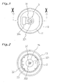
- Fig. 1 is a plan view showing an embodiment of the present invention.
- Fig. 2 is a base view of Fig. 1.
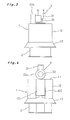
- Fig. 3 is a front view of Fig. 1.
- Fig. 4 is a left side view of Fig. 1.
- Fig. 5 is a cross sectional view of Fig. 1 along line X-X.
- Fig. 6 is a left side view of an inside guide member that is shown in Fig. 1.
- Fig. 7 is a perspective view of a main portion of the inside guide member that is shown in Fig. 1.
- Fig. 8 is a cross sectional view that is similar to Fig. 5, showing another embodiment of the present invention.
- Figs. 9(a)-9(b) are views for explaining how a transfer needle assembly according to the present invention is used.
-
- As shown in Figs. 1 to 5, the transfer needle assembly according to the present invention includes a cap-like
outside guide member 1, a tubularinside guide member 2, and apuncture member 3. Thepuncture member 3 is a tubular member having atip fitting portion 31 at its proximal end and apuncture needle 32 at its distal end. Thepuncture needle 32 is provided with agas passage 322 which is provided with anair filter 33 in anopening portion 324 and aliquid passage 321 which communicates with thetip insertion portion 31. Further, theinside guide member 2 is capable of sliding along an inner wall of askirt portion 12 of theoutside guide member 1 from a position where a distal end of thepuncture needle 32 is receded in the inside of theinside guide member 2, to a position where the distal end of thepuncture needle 32 projects outside of theinside guide member 2. Theoutside guide member 1 and theinside guide member 2 are releasably engaged with each other in the position where the distal end of thepuncture needle 32 is receded in the inside of theinside guide member 2, so as to be incapable of sliding; and the engagement between theoutside guide member 1 and theinside guide member 2 is releasable by inserting a mouth portion of a vial into theinside guide member 2. - The
outside guide member 1 is a cap-like member that is normally formed from a flexible resin such as polypropylene, polyethylene, polyester, polyvinyl chloride, or ABS resin. Theoutside guide member 1 has atop surface 11 and atubular skirt portion 12. Theinside guide portion 2 is inserted into theskirt portion 12, and thepuncture member 3 is provided in thetop surface 11, passing through thetop surface 11. - When the
inside guide member 2 is gripped by hand, the hand may get in the way and it becomes difficult to slide theinside guide member 2. Acollar 13 having a funnel shape, for example, which inclines to the outside in a distal end direction may also be provided in the distal end of theskirt portion 12 of theoutside guide member 1 in such a manner that theinside guide member 2 is not gripped during vial insertion. - The
inside guide member 2 is a tubular member that is formed from a material similar to that used for theoutside guide member 1. Theinside guide member 2 has an outer diameter that is slightly smaller than the inner diameter of theskirt portion 12 so that it is possible for theinside guide member 2 to slide along an inner wall of theskirt portion 12 of theoutside guide member 1. - The
outside guide member 1 and theinside guide member 2 are releasably engaged in the position where a tip of thepuncture needle 32 is receded in the inside of theinside guide member 2 so as to be incapable of sliding with respect to each other before use. This engagement can be released by inserting amouth portion 41 of a vial 4 (refer to Fig. 9b) into theinside guide member 2. When the engagement between theoutside guide member 1 and theinside guide member 2 is released, it becomes possible to slide theinside guide member 2 along the inner wall of theskirt portion 12 of theoutside guide member 1, from a position where the tip portion of thepuncture needle 32 is receded, or recessed, in theinside guide member 2 to a position where thepuncture needle 32 projects to the outside. - The engagement between the
outside guide member 1 and theinside guide member 2 as described above is, for example, structured as shown in Figs. 5 and 8. That is, in theoutside guide member 1, anannular projection 121 is provided in an inner wall of a distal end of theskirt portion 12, a plurality ofslits 123 extending substantially in the axial direction of the outside guide member (refer to Fig. 4) are formed in a portion of the proximal end side, with respect to thisannular projection 121, of theskirt portion 12, and a plurality of flexibleengaging claws 122 that incline toward the inside in a distal end direction are formed by pairs of slits 123 (as best shown in Fig. 4). - In the
inside guide member 2, on its proximal end side, anannular projection 21 is provided in an outer wall of its proximal end as shown in Figs. 6 and 7. A plurality ofslits 25 extending substantially in the axial direction of the inside guide member (refer to Fig. 6) are formed in the proximal end portion at positions corresponding to the engagingclaws 122, and a plurality of flexible pushingclaws 22 that incline toward the inside ofinside guide member 2 in a proximal end direction are formed between pairs of theslits 25. Before use, in the position where the distal end of thepuncture needle 3 is receded in the inside of theinside guide member 2, the engagingclaws 122 engage (in the sense of collide with), or abut against, theproximal end 24 of theinside guide member 2 and theannular projection 121 of theoutside guide member 1 engages theannular projection 21 of theinside guide member 2. By inserting themouth portion 41 of thevial 4 into theinside guide member 2, the pushingclaws 22 are deformed to bend outward, and the outwardly bent pushingclaws 22 push the engagingclaws 122 to the outside, thereby releasing the engagement between theoutside guide member 1 and theinside guide member 2. It should be noted thatreference numeral 221 denotes a pushing portion of the pushingclaw 22. The pushing portion is formed projecting to the outside so as to be situated at a height where it reliably releases the engagement between the engagingclaw 122 and theproximal end 24 of theinside guide member 2 when thevial mouth portion 41 is inserted into theinside guide member 2. - A plurality of
vertical ribs 23 may also be provided in theinside guide member 2 so that thevial 4 slides more easily along the inner wall of theinside guide member 2. - The
puncture member 3 may be formed integrally with theoutside guide member 1 as shown in Fig. 8, and may also be provided separately from theoutside guide member 1 as shown in Fig. 5. When thepuncture member 3 is provided separately from theoutside guide member 1, a punctureneedle insertion portion 14 having a hole, or opening, 141 that passes through thetop surface 11 may be formed axially in thetop surface 11 of theoutside guide member 1 as shown in Fig. 2, for example. Thepuncture needle 32 of thepuncture portion 3, which is formed separately from theoutside guide member 1, may be inserted into thehole 141 of the punctureneedle insertion portion 14. It should be noted that anannular groove 142 may also be formed in the inner wall of opening 141, engaging with anannular projection 323 that is formed in an outer wall of thepuncture needle 32 so that thepuncture member 3 does not fall off from the punctureneedle insertion portion 14 during use. - Use of the transfer needle assembly of the present invention is explained next using Fig. 9. First, a transfer needle assembly TN like that shown in Fig. 5 is prepared (Fig. 9a). The engaging
claw 122 of theoutside guide member 1 is engaged with theproximal end 24 of theinside guide member 2 at this point (Fig. 9d). Next, themouth portion 41 of thevial 4 is inserted into the transfer needle assembly TN. The transfer needle assembly TN is pushed forward to a position where themouth portion 41 of thevial 4 pushes the pushingclaw 22 of theinside guide member 2 and deflects the pushingclaw 22 to the outside (Fig. 9b). At this point, the engagingclaw 122 is pushed on and deflects to the outside by the pushingclaw 22 that has been deflected to the outside. The engagement between the engagingclaw 122 and theproximal end 24 of theinside guide member 2 is thus released (Fig. 9e). When the transfer needle assembly TN is pushed further forward, arubber stopper 42 of themouth portion 41 of the vial is pricked by thepuncture needle 32 of thepuncture member 3, and the inside of thevial 4 communicates with the outside through the transfer needle assembly TN (Fig. 9c). If a syringe tip (not shown) is fitted onto thetip fitting portion 31 in this state, a solution or the like filled into the syringe in advance can be injected into the vial. Further, a medical liquid after dissolution can be aspirated from within thevial 4 into the syringe. - As is apparent from the description above, the inside of a vial can be communicated with the outside simply by a hand pushing operation when employing the present invention, and therefore dissolution operations are easy. Further, the needle tip of the transfer needle assembly is receded in the inside of the inside guide member before use, and therefore contamination of the needle tip, and injuries caused by the needle tip, can be avoided when performing dissolution operations. Furthermore, the puncture needle can prick right through a center portion of the rubber stopper of a vial due to the inside guide member, and therefore liquid leakage during dissolution operations can be prevented.
Claims (6)
- A transfer needle assembly comprising:wherein:a cap-like outside guide member (1) having a top surface (11) and a skirt portion (12);a tubular inside guide member (2) that is positioned in the outside guide member (1); anda puncture member (3) which passes through the top surface (11) of the outside guide member (1) and has a proximal end and a distal end,the puncture member (3) is a tubular member having at its proximal end a tip fitting portion (31) for fitting a syringe tip and having at its distal end a puncture needle (32);the puncture needle (32) is provided with a liquid passage (321);the liquid passage (321) communicates with the tip fitting portion (31);the inside guide member (2) is capable of sliding along an inner wall of the skirt portion (12) of the outside guide member (1) from a position where a distal end of the puncture needle (32) is receded in an inside of the inside guide member (2), to a position where the distal end of the puncture needle (32) projects outside of the inside guide member (2);in the position where the distal end of the puncture needle (32) is receded in the inside of the inside guide member (2), the outside guide member (1) and the inside guide member (2) are releasably engaged with each other so as to be incapable of sliding; andthe engagement between the outside guide member (1) and the inside guide member (2) is releasable by insertion of a mouth portion (41) of a vial (4) into the inside guide member (2).
- A transfer needle assembly according to claim 1, wherein the skirt portion (12) of the outside guide member (1) includes:wherein a proximal end side of the inside guide member (2) includes:an annular projection (121) provided in an inner wall of a distal end of the skirt portion (12);a plurality of slits (123) extending in an axial direction of the outside guide member (1) formed in a portion of the skirt portion (12) on a proximal end side with respect to the annular projection (121); anda plurality of flexible engaging claws (122) formed between pairs of the plurality of slits (123), the plurality of flexible engaging claws (122) inclining toward an inside of the outside guide member (1) in a distal end direction,wherein, at the position where the distal end of the puncture needle (3) is receded in the inside of the inside guide member (2), the engaging claws (122) and the proximal end (24) of the inside guide member (2) are engaged with each other and the annular projection (121) of the outside guide member (1) and the annular projection (21) of the inside guide member (2) are engaged with each other, and by inserting the mouth portion (41) of the vial (4) into the inside guide member (2), the pushing claws (22) push the engaging claws (122) to the outside, causing the engaging claws (122) to deform and release the engagement between the outside guide member (1) and the inside guide member (2).an annular projection (21) provided in an outer wall of a proximal end;a plurality of slits (25) extending in an axial direction of the inside guide member (2) formed in a proximal end portion of the inside guide member corresponding to the plurality of engaging claws (122); anda plurality of flexible pushing claws (22) formed between pairs of the plurality of slits (25), the plurality of flexible pushing claws (22) inclining toward an inside of the inside guide member (2) in a proximal end direction, and
- A transfer needle assembly according to claim 1 or 2, wherein the puncture member (3) is formed integrally with the outside guide member (1).
- A transfer needle assembly according to claim 1 or 2, comprising a puncture needle insertion portion (14) axially provided in the top surface (11) of the outside guide member (1) and having an opening (141) that passes through the top surface (11),
wherein the puncture member (3) is provided separately from the outside guide member (1) and is inserted into the opening (141) of the puncture needle insertion portion (14). - A transfer needle assembly according to any one of claims 1-4, comprising a plurality of vertical ribs (23) provided in an inner wall of the inside guide member (2).
- A transfer needle assembly according to any one of claims 1-5, comprising a collar (13) formed in the distal end of the skirt portion (12) of the outside guide member (1), the collar (13) inclining to the outside in the distal end direction of the outside guide member (1).
Applications Claiming Priority (2)
| Application Number | Priority Date | Filing Date | Title |
|---|---|---|---|
| JP2002367640 | 2002-12-19 | ||
| JP2002367640A JP4341239B2 (en) | 2002-12-19 | 2002-12-19 | Liquid transfer tool |
Publications (2)
| Publication Number | Publication Date |
|---|---|
| EP1430864A1 true EP1430864A1 (en) | 2004-06-23 |
| EP1430864B1 EP1430864B1 (en) | 2010-11-17 |
Family
ID=32376286
Family Applications (1)
| Application Number | Title | Priority Date | Filing Date |
|---|---|---|---|
| EP20030029066 Expired - Lifetime EP1430864B1 (en) | 2002-12-19 | 2003-12-17 | Transfer needle assembly |
Country Status (5)
| Country | Link |
|---|---|
| US (1) | US7452348B2 (en) |
| EP (1) | EP1430864B1 (en) |
| JP (1) | JP4341239B2 (en) |
| AT (1) | ATE488211T1 (en) |
| DE (1) | DE60334967D1 (en) |
Cited By (9)
| Publication number | Priority date | Publication date | Assignee | Title |
|---|---|---|---|---|
| EP1973486A4 (en) * | 2005-12-30 | 2011-10-19 | Carefusion 303 Inc | REDUCED DIAMETER CANAL CAPABLE MEDIUM ADAPTER AND ENLARGED EVENT LIGHT |
| US8141601B2 (en) | 2008-10-02 | 2012-03-27 | Roche Diagnostics Operations, Inc. | Manual filling aid with push button fill |
| CN104540490A (en) * | 2012-06-27 | 2015-04-22 | 卡麦尔药物股份公司 | Medical connecting device |
| CN104780892A (en) * | 2012-11-01 | 2015-07-15 | 大冢科技株式会社 | Drug container storage device, drug container storage system, and drug suction method |
| CN106510813A (en) * | 2016-12-09 | 2017-03-22 | 成都五义医疗科技有限公司 | No-knife puncture needle capable of deforming locally |
| EP3184440A3 (en) * | 2013-02-07 | 2017-09-20 | Equashield Medical Ltd. | Improvements to a closed drug transfer system |
| US10195112B2 (en) | 2012-11-26 | 2019-02-05 | Becton Dickinson France | Adaptor for multidose medical container |
| US12102597B2 (en) | 2014-03-27 | 2024-10-01 | Medac Gesellschaft für klinische Spezialpräparate mbH | Transfer device |
| US12396925B2 (en) | 2020-08-20 | 2025-08-26 | B. Braun Melsungen Ag | Filter system for a closed fluid-transfer system with pressure equalization |
Families Citing this family (71)
| Publication number | Priority date | Publication date | Assignee | Title |
|---|---|---|---|---|
| IL114960A0 (en) | 1995-03-20 | 1995-12-08 | Medimop Medical Projects Ltd | Flow control device |
| IL161660A0 (en) | 2004-04-29 | 2004-09-27 | Medimop Medical Projects Ltd | Liquid drug delivery device |
| EP1799288A4 (en) * | 2004-09-16 | 2008-11-19 | Inviro Medical Devices Inc | Disposable safety syringe to prevent needlestick injuries and reuse |
| FR2878737B1 (en) * | 2004-12-07 | 2007-03-16 | Maptech Soc Par Actions Simpli | SAFETY DEVICE FOR A BOTTLE FOR MEDICAL USE |
| DK1919432T3 (en) | 2005-08-11 | 2012-01-30 | Medimop Medical Projects Ltd | Liquid Medication Transfer Devices for Safe Safe Resting Connection on Medical Vials |
| NZ573048A (en) | 2006-05-25 | 2011-08-26 | Bayer Healthcare Llc | Reconstitution device |
| EP2101711A1 (en) * | 2006-11-30 | 2009-09-23 | Medi-Physics, Inc. | Dual-lumen needle with an elongate notch opening |
| IL182605A0 (en) | 2007-04-17 | 2007-07-24 | Medimop Medical Projects Ltd | Fluid control device with manually depressed actuator |
| WO2009038860A2 (en) | 2007-09-18 | 2009-03-26 | Medeq Llc | Medicament mixing and injection apparatus |
| IL186290A0 (en) | 2007-09-25 | 2008-01-20 | Medimop Medical Projects Ltd | Liquid drug delivery devices for use with syringe having widened distal tip |
| JP5265666B2 (en) * | 2008-04-01 | 2013-08-14 | 生化学工業株式会社 | Chemical liquid discharge part sealing cap |
| US9056702B2 (en) * | 2008-09-12 | 2015-06-16 | Nestec S.A. | Closure for containers |
| US8512309B2 (en) * | 2009-01-15 | 2013-08-20 | Teva Medical Ltd. | Vial adapter element |
| USD641080S1 (en) | 2009-03-31 | 2011-07-05 | Medimop Medical Projects Ltd. | Medical device having syringe port with locking mechanism |
| USD616984S1 (en) | 2009-07-02 | 2010-06-01 | Medimop Medical Projects Ltd. | Vial adapter having side windows |
| USD630732S1 (en) | 2009-09-29 | 2011-01-11 | Medimop Medical Projects Ltd. | Vial adapter with female connector |
| IL201323A0 (en) | 2009-10-01 | 2010-05-31 | Medimop Medical Projects Ltd | Fluid transfer device for assembling a vial with pre-attached female connector |
| MX344382B (en) | 2009-10-23 | 2016-12-14 | Amgen Inc * | Vial adapter and system. |
| IL202069A0 (en) | 2009-11-12 | 2010-06-16 | Medimop Medical Projects Ltd | Fluid transfer device with sealing arrangement |
| IL202070A0 (en) | 2009-11-12 | 2010-06-16 | Medimop Medical Projects Ltd | Inline liquid drug medical device |
| EP2361599A1 (en) * | 2010-02-22 | 2011-08-31 | Fresenius Kabi Deutschland GmbH | Device for supplying or removing a liquid into or out of a container |
| WO2011104711A1 (en) | 2010-02-24 | 2011-09-01 | Medimop Medical Projects Ltd | Fluid transfer assembly with venting arrangement |
| BR112012020829B1 (en) | 2010-02-24 | 2020-04-14 | Medimop Medical Projects Ltd | liquid drug transfer device for use with a medical bottle |
| US20120078214A1 (en) * | 2010-09-28 | 2012-03-29 | Tyco Healthcare Group Lp | Vial transfer needle assembly |
| USD669980S1 (en) | 2010-10-15 | 2012-10-30 | Medimop Medical Projects Ltd. | Vented vial adapter |
| IL209290A0 (en) | 2010-11-14 | 2011-01-31 | Medimop Medical Projects Ltd | Inline liquid drug medical device having rotary flow control member |
| JP5977734B2 (en) | 2011-03-18 | 2016-08-24 | テルモ株式会社 | Puncture needle integrated adapter and method of using the puncture needle integrated adapter |
| CA2831100C (en) | 2011-03-31 | 2020-02-18 | Mark Dominis Holt | Vial adapter and system |
| IL212420A0 (en) | 2011-04-17 | 2011-06-30 | Medimop Medical Projects Ltd | Liquid drug transfer assembly |
| IL215699A0 (en) | 2011-10-11 | 2011-12-29 | Medimop Medical Projects Ltd | Liquid drug reconstitution assemblage for use with iv bag and drug vial |
| CN103196455B (en) * | 2012-01-09 | 2016-09-21 | 北京四维图新科技股份有限公司 | The display method of road name, device, server and system |
| USD720451S1 (en) | 2012-02-13 | 2014-12-30 | Medimop Medical Projects Ltd. | Liquid drug transfer assembly |
| USD674088S1 (en) | 2012-02-13 | 2013-01-08 | Medimop Medical Projects Ltd. | Vial adapter |
| USD737436S1 (en) | 2012-02-13 | 2015-08-25 | Medimop Medical Projects Ltd. | Liquid drug reconstitution assembly |
| IL219065A0 (en) | 2012-04-05 | 2012-07-31 | Medimop Medical Projects Ltd | Fluid transfer device with manual operated cartridge release arrangement |
| US11014696B2 (en) * | 2017-07-12 | 2021-05-25 | Vanrx Pharmasystems Inc. | Purgeable pharmaceutical fill needle |
| IL221635A0 (en) | 2012-08-26 | 2012-12-31 | Medimop Medical Projects Ltd | Drug vial mixing and transfer device for use with iv bag and drug vial |
| IL221634A0 (en) | 2012-08-26 | 2012-12-31 | Medimop Medical Projects Ltd | Universal drug vial adapter |
| JP5868555B2 (en) * | 2012-09-13 | 2016-02-24 | メディモップ・メディカル・プロジェクツ・リミテッド | Nested female vial adapter |
| DE102012113002B4 (en) | 2012-10-01 | 2014-04-30 | Medac Gesellschaft für klinische Spezialpräparate mbH | Transfer device for removing or transferring a fluid |
| USD734868S1 (en) | 2012-11-27 | 2015-07-21 | Medimop Medical Projects Ltd. | Drug vial adapter with downwardly depending stopper |
| EP2929867B1 (en) | 2012-12-10 | 2018-05-23 | Nipro Corporation | Coupling device |
| IL225734A0 (en) | 2013-04-14 | 2013-09-30 | Medimop Medical Projects Ltd | Ready-to-use drug vial assemblages including drug vial and drug vial closure having fluid transfer member, and drug vial closure therefor |
| BR112015027555B1 (en) | 2013-05-10 | 2022-02-01 | Medimop Medical Projects Ltd | Medical device for use with a needleless syringe, a vial and a liquid carrier to fill the needleless syringe with an injection solution for injection into a patient |
| USD767124S1 (en) | 2013-08-07 | 2016-09-20 | Medimop Medical Projects Ltd. | Liquid transfer device with integral vial adapter |
| USD765837S1 (en) | 2013-08-07 | 2016-09-06 | Medimop Medical Projects Ltd. | Liquid transfer device with integral vial adapter |
| CN205626622U (en) | 2013-08-07 | 2016-10-12 | 麦迪麦珀医疗工程有限公司 | Fluid transfer devices for use with infusion containers |
| USD757933S1 (en) | 2014-09-11 | 2016-05-31 | Medimop Medical Projects Ltd. | Dual vial adapter assemblage |
| JP6358724B2 (en) | 2015-01-05 | 2018-07-18 | ウエスト・ファーマ.サービシーズ・イスラエル,リミテッド | Dual vial adapter assembly with easy removable pill adapter to ensure accurate use |
| CN113143759B (en) | 2015-07-16 | 2024-01-30 | 西部制药服务以色列有限公司 | Liquid drug transfer device for secure telescopic snap-fit on an injection vial |
| USD801522S1 (en) | 2015-11-09 | 2017-10-31 | Medimop Medical Projects Ltd. | Fluid transfer assembly |
| CN115721558A (en) | 2015-11-25 | 2023-03-03 | 西部制药服务以色列有限公司 | Dual vial adapter assembly comprising a drug vial adapter having a self-sealing inlet valve |
| IL245803A0 (en) | 2016-05-24 | 2016-08-31 | West Pharma Services Il Ltd | Dual vial adapter assemblages including vented drug vial adapter and vented liquid vial adapter |
| IL245800A0 (en) | 2016-05-24 | 2016-08-31 | West Pharma Services Il Ltd | Dual vial adapter assemblages including identical twin vial adapters |
| IL246073A0 (en) | 2016-06-06 | 2016-08-31 | West Pharma Services Il Ltd | Fluid transfer devices for use with drug pump cartridge having slidable driving plunger |
| IL247376A0 (en) | 2016-08-21 | 2016-12-29 | Medimop Medical Projects Ltd | Syringe assembly |
| USD832430S1 (en) | 2016-11-15 | 2018-10-30 | West Pharma. Services IL, Ltd. | Dual vial adapter assemblage |
| IL249408A0 (en) | 2016-12-06 | 2017-03-30 | Medimop Medical Projects Ltd | A device for transporting fluids for use with an infusion fluid container and a hand tool similar to a plunger to release a vial from it |
| IL251458A0 (en) | 2017-03-29 | 2017-06-29 | Medimop Medical Projects Ltd | User actuated liquid drug transfer devices for use in ready-to-use (rtu) liquid drug transfer assemblages |
| IL254802A0 (en) | 2017-09-29 | 2017-12-31 | Medimop Medical Projects Ltd | Dual vial adapter assemblages with twin vented female vial adapters |
| JP1630477S (en) | 2018-07-06 | 2019-05-07 | ||
| USD923812S1 (en) | 2019-01-16 | 2021-06-29 | West Pharma. Services IL, Ltd. | Medication mixing apparatus |
| JP1648075S (en) | 2019-01-17 | 2019-12-16 | ||
| EP3911292B1 (en) | 2019-01-18 | 2022-12-28 | West Pharma Services IL, Ltd. | Liquid transfer devices for use with intravenous (iv) bottles |
| CN113490477B (en) | 2019-01-31 | 2024-09-27 | 西医药服务以色列有限公司 | Liquid handling device |
| CN113677382B (en) | 2019-04-09 | 2023-06-09 | 西医药服务以色列有限公司 | Liquid delivery device with integrated syringe |
| JP7001838B2 (en) | 2019-04-30 | 2022-01-20 | ウェスト ファーマ サービシーズ イスラエル リミテッド | Dual lumen IV liquid transfer device with spikes |
| USD956958S1 (en) | 2020-07-13 | 2022-07-05 | West Pharma. Services IL, Ltd. | Liquid transfer device |
| CN113122438B (en) * | 2021-06-01 | 2025-01-24 | 青岛速知科技有限公司 | Cell extraction component and cell extraction instrument |
| WO2024127823A1 (en) * | 2022-12-15 | 2024-06-20 | ニプロ株式会社 | Drug transfer kit |
| WO2025210959A1 (en) * | 2024-04-04 | 2025-10-09 | ニプロ株式会社 | Transfer device |
Citations (6)
| Publication number | Priority date | Publication date | Assignee | Title |
|---|---|---|---|---|
| EP0126718A2 (en) * | 1983-05-20 | 1984-11-28 | Bengt Gustavsson | A device for transferring a substance from one vessel to another and further to the intended application |
| EP0311787A2 (en) * | 1987-10-14 | 1989-04-19 | FARMITALIA CARLO ERBA S.r.l. | Apparatus with safety locking members, for connecting a syringe to a bottle containing a medicament |
| US5356380A (en) * | 1991-10-23 | 1994-10-18 | Baxter International Inc. | Drug delivery system |
| US5984899A (en) * | 1993-02-11 | 1999-11-16 | Beech Medical Products, Inc. | Needle protector device having a lockable protective cover which is unlockable during actuation |
| US6159192A (en) * | 1997-12-04 | 2000-12-12 | Fowles; Thomas A. | Sliding reconstitution device with seal |
| JP2002360593A (en) | 2001-06-12 | 2002-12-17 | Japan Science & Technology Corp | Graft grasper |
Family Cites Families (13)
| Publication number | Priority date | Publication date | Assignee | Title |
|---|---|---|---|---|
| IT1173370B (en) * | 1984-02-24 | 1987-06-24 | Erba Farmitalia | SAFETY DEVICE TO CONNECT A SYRINGE TO THE MOUTH OF A BOTTLE CONTAINING A DRUG OR A TUBE FOR DISPENSING THE SYRINGE DRUG |
| JP3146616B2 (en) | 1992-04-01 | 2001-03-19 | 株式会社ニッショー | Dry formulation dissolution kit |
| JP3475414B2 (en) | 1994-01-28 | 2003-12-08 | ニプロ株式会社 | Adapter for co-infusion |
| GB9609563D0 (en) * | 1996-05-08 | 1996-07-10 | Sterimatic Holdings Ltd | Venting devices |
| FR2753624B1 (en) * | 1996-09-25 | 1999-04-16 | Biodome | CONNECTION DEVICE, PARTICULARLY BETWEEN A CONTAINER WITH PERFORABLE CAP AND A SYRINGE |
| JP3303285B2 (en) | 1997-04-08 | 2002-07-15 | ニプロ株式会社 | Solution-filled syringe for mixing two components |
| JP3303289B2 (en) | 1997-05-23 | 2002-07-15 | ニプロ株式会社 | Solution-filled syringe for mixing two components |
| US6378714B1 (en) * | 1998-04-20 | 2002-04-30 | Becton Dickinson And Company | Transferset for vials and other medical containers |
| US6358236B1 (en) * | 1998-08-06 | 2002-03-19 | Baxter International Inc. | Device for reconstituting medicaments for injection |
| US6453956B2 (en) * | 1999-11-05 | 2002-09-24 | Medtronic Minimed, Inc. | Needle safe transfer guard |
| JP4372310B2 (en) * | 2000-04-10 | 2009-11-25 | ニプロ株式会社 | Adapter for mixed injection |
| JP4552271B2 (en) | 2000-05-15 | 2010-09-29 | ニプロ株式会社 | Liquid transfer tool |
| JP4515626B2 (en) | 2000-12-08 | 2010-08-04 | ニプロ株式会社 | Liquid transfer tool |
-
2002
- 2002-12-19 JP JP2002367640A patent/JP4341239B2/en not_active Expired - Lifetime
-
2003
- 2003-12-11 US US10/733,198 patent/US7452348B2/en active Active
- 2003-12-17 EP EP20030029066 patent/EP1430864B1/en not_active Expired - Lifetime
- 2003-12-17 DE DE60334967T patent/DE60334967D1/en not_active Expired - Lifetime
- 2003-12-17 AT AT03029066T patent/ATE488211T1/en not_active IP Right Cessation
Patent Citations (6)
| Publication number | Priority date | Publication date | Assignee | Title |
|---|---|---|---|---|
| EP0126718A2 (en) * | 1983-05-20 | 1984-11-28 | Bengt Gustavsson | A device for transferring a substance from one vessel to another and further to the intended application |
| EP0311787A2 (en) * | 1987-10-14 | 1989-04-19 | FARMITALIA CARLO ERBA S.r.l. | Apparatus with safety locking members, for connecting a syringe to a bottle containing a medicament |
| US5356380A (en) * | 1991-10-23 | 1994-10-18 | Baxter International Inc. | Drug delivery system |
| US5984899A (en) * | 1993-02-11 | 1999-11-16 | Beech Medical Products, Inc. | Needle protector device having a lockable protective cover which is unlockable during actuation |
| US6159192A (en) * | 1997-12-04 | 2000-12-12 | Fowles; Thomas A. | Sliding reconstitution device with seal |
| JP2002360593A (en) | 2001-06-12 | 2002-12-17 | Japan Science & Technology Corp | Graft grasper |
Cited By (20)
| Publication number | Priority date | Publication date | Assignee | Title |
|---|---|---|---|---|
| EP1973486A4 (en) * | 2005-12-30 | 2011-10-19 | Carefusion 303 Inc | REDUCED DIAMETER CANAL CAPABLE MEDIUM ADAPTER AND ENLARGED EVENT LIGHT |
| AU2006332817B2 (en) * | 2005-12-30 | 2012-04-05 | Carefusion 303, Inc. | Medical vial adapter with reduced diameter cannula and enlarged vent lumen |
| US8141601B2 (en) | 2008-10-02 | 2012-03-27 | Roche Diagnostics Operations, Inc. | Manual filling aid with push button fill |
| US8505833B2 (en) | 2008-10-02 | 2013-08-13 | Roche Diagnostics Operations, Inc. | Manual filling aid with push button fill |
| CN108969357B (en) * | 2012-06-27 | 2021-09-07 | 卡麦尔药物股份公司 | Vial connector for use in a medical fluid transfer device |
| EP3753545A1 (en) * | 2012-06-27 | 2020-12-23 | Carmel Pharma AB | Medical connecting device |
| EP2866769A4 (en) * | 2012-06-27 | 2016-02-17 | Carmel Pharma Ab | MEDICAL CONNECTION DEVICE |
| US12115129B2 (en) | 2012-06-27 | 2024-10-15 | Carmel Pharma Ab | Medical connecting device |
| CN104540490A (en) * | 2012-06-27 | 2015-04-22 | 卡麦尔药物股份公司 | Medical connecting device |
| CN108969357A (en) * | 2012-06-27 | 2018-12-11 | 卡麦尔药物股份公司 | Bottle connector in medical fluid transfer equipment |
| US10478382B2 (en) | 2012-06-27 | 2019-11-19 | Carmel Pharma Ab | Medical connecting device |
| EP2915515A4 (en) * | 2012-11-01 | 2016-07-27 | Otsuka Techno Corp | DRUG CONTAINER STORAGE DEVICE, DRUG CONTAINER STORAGE SYSTEM, AND METHOD FOR VACUUM MEDICINE |
| CN104780892A (en) * | 2012-11-01 | 2015-07-15 | 大冢科技株式会社 | Drug container storage device, drug container storage system, and drug suction method |
| US10195112B2 (en) | 2012-11-26 | 2019-02-05 | Becton Dickinson France | Adaptor for multidose medical container |
| EP3424824A1 (en) * | 2013-02-07 | 2019-01-09 | Equashield Medical Ltd. | Improvements to a closed drug transfer system |
| EP3184440A3 (en) * | 2013-02-07 | 2017-09-20 | Equashield Medical Ltd. | Improvements to a closed drug transfer system |
| US12102597B2 (en) | 2014-03-27 | 2024-10-01 | Medac Gesellschaft für klinische Spezialpräparate mbH | Transfer device |
| CN106510813B (en) * | 2016-12-09 | 2023-05-26 | 成都五义医疗科技有限公司 | A locally deformable knifeless puncture needle |
| CN106510813A (en) * | 2016-12-09 | 2017-03-22 | 成都五义医疗科技有限公司 | No-knife puncture needle capable of deforming locally |
| US12396925B2 (en) | 2020-08-20 | 2025-08-26 | B. Braun Melsungen Ag | Filter system for a closed fluid-transfer system with pressure equalization |
Also Published As
| Publication number | Publication date |
|---|---|
| JP2004194953A (en) | 2004-07-15 |
| ATE488211T1 (en) | 2010-12-15 |
| US7452348B2 (en) | 2008-11-18 |
| EP1430864B1 (en) | 2010-11-17 |
| JP4341239B2 (en) | 2009-10-07 |
| US20040122374A1 (en) | 2004-06-24 |
| DE60334967D1 (en) | 2010-12-30 |
Similar Documents
| Publication | Publication Date | Title |
|---|---|---|
| EP1430864B1 (en) | Transfer needle assembly | |
| EP1396250B1 (en) | Transfer needle assembly | |
| US6030366A (en) | Syringe guard system for a unit dose syringe | |
| US10052438B2 (en) | Tamper evident needle guard for syringes | |
| US6626868B1 (en) | Needle apparatus | |
| US4892107A (en) | Single use, safety blood collection device | |
| US5195985A (en) | Syringe having a retractable needle | |
| JP3303095B2 (en) | Vial access cannula assembly | |
| EP0957957B1 (en) | Shielding means | |
| US20050096601A1 (en) | Syringe with integral safety system | |
| US7189218B2 (en) | Needle apparatus with quick/safe release mechanism | |
| EP0652020A2 (en) | Retractable hypodermic needle assembly | |
| EP0331452A2 (en) | Safety needled medical devices | |
| CN114983819A (en) | Liquid medication transfer device for use with untouched individual injection vial release kits | |
| JPH09290012A (en) | Liquid transfer device and liquid transfer method using the device | |
| US7357783B2 (en) | Safety system for a blood collection device | |
| JPH0747125A (en) | Luer needle unit and syringe | |
| JP2001518366A (en) | Disposable self-shielding unit dose syringe guard | |
| US20040206416A1 (en) | Safety shield needle protector | |
| JP4722365B2 (en) | Safety needle medical device | |
| CN213252047U (en) | Anti-drop infusion apparatus and bottle inserting needle thereof | |
| WO2001080931A2 (en) | Safety device for a syringe | |
| AU752790B2 (en) | A needle apparatus | |
| MXPA98000792A (en) | Retractible and destructi safety syringe |
Legal Events
| Date | Code | Title | Description |
|---|---|---|---|
| PUAI | Public reference made under article 153(3) epc to a published international application that has entered the european phase |
Free format text: ORIGINAL CODE: 0009012 |
|
| AK | Designated contracting states |
Kind code of ref document: A1 Designated state(s): AT BE BG CH CY CZ DE DK EE ES FI FR GB GR HU IE IT LI LU MC NL PT RO SE SI SK TR |
|
| AX | Request for extension of the european patent |
Extension state: AL LT LV MK |
|
| 17P | Request for examination filed |
Effective date: 20041125 |
|
| AKX | Designation fees paid |
Designated state(s): AT BE BG CH CY CZ DE DK EE ES FI FR GB GR HU IE IT LI LU MC NL PT RO SE SI SK TR |
|
| 17Q | First examination report despatched |
Effective date: 20050601 |
|
| GRAP | Despatch of communication of intention to grant a patent |
Free format text: ORIGINAL CODE: EPIDOSNIGR1 |
|
| GRAS | Grant fee paid |
Free format text: ORIGINAL CODE: EPIDOSNIGR3 |
|
| GRAA | (expected) grant |
Free format text: ORIGINAL CODE: 0009210 |
|
| AK | Designated contracting states |
Kind code of ref document: B1 Designated state(s): AT BE BG CH CY CZ DE DK EE ES FI FR GB GR HU IE IT LI LU MC NL PT RO SE SI SK TR |
|
| REG | Reference to a national code |
Ref country code: GB Ref legal event code: FG4D |
|
| REG | Reference to a national code |
Ref country code: CH Ref legal event code: EP |
|
| REG | Reference to a national code |
Ref country code: IE Ref legal event code: FG4D |
|
| REF | Corresponds to: |
Ref document number: 60334967 Country of ref document: DE Date of ref document: 20101230 Kind code of ref document: P |
|
| REG | Reference to a national code |
Ref country code: NL Ref legal event code: VDEP Effective date: 20101117 |
|
| PG25 | Lapsed in a contracting state [announced via postgrant information from national office to epo] |
Ref country code: PT Free format text: LAPSE BECAUSE OF FAILURE TO SUBMIT A TRANSLATION OF THE DESCRIPTION OR TO PAY THE FEE WITHIN THE PRESCRIBED TIME-LIMIT Effective date: 20110317 Ref country code: NL Free format text: LAPSE BECAUSE OF FAILURE TO SUBMIT A TRANSLATION OF THE DESCRIPTION OR TO PAY THE FEE WITHIN THE PRESCRIBED TIME-LIMIT Effective date: 20101117 Ref country code: SI Free format text: LAPSE BECAUSE OF FAILURE TO SUBMIT A TRANSLATION OF THE DESCRIPTION OR TO PAY THE FEE WITHIN THE PRESCRIBED TIME-LIMIT Effective date: 20101117 Ref country code: SE Free format text: LAPSE BECAUSE OF FAILURE TO SUBMIT A TRANSLATION OF THE DESCRIPTION OR TO PAY THE FEE WITHIN THE PRESCRIBED TIME-LIMIT Effective date: 20101117 Ref country code: CY Free format text: LAPSE BECAUSE OF FAILURE TO SUBMIT A TRANSLATION OF THE DESCRIPTION OR TO PAY THE FEE WITHIN THE PRESCRIBED TIME-LIMIT Effective date: 20101117 Ref country code: FI Free format text: LAPSE BECAUSE OF FAILURE TO SUBMIT A TRANSLATION OF THE DESCRIPTION OR TO PAY THE FEE WITHIN THE PRESCRIBED TIME-LIMIT Effective date: 20101117 Ref country code: BG Free format text: LAPSE BECAUSE OF FAILURE TO SUBMIT A TRANSLATION OF THE DESCRIPTION OR TO PAY THE FEE WITHIN THE PRESCRIBED TIME-LIMIT Effective date: 20110217 Ref country code: AT Free format text: LAPSE BECAUSE OF FAILURE TO SUBMIT A TRANSLATION OF THE DESCRIPTION OR TO PAY THE FEE WITHIN THE PRESCRIBED TIME-LIMIT Effective date: 20101117 |
|
| PG25 | Lapsed in a contracting state [announced via postgrant information from national office to epo] |
Ref country code: GR Free format text: LAPSE BECAUSE OF FAILURE TO SUBMIT A TRANSLATION OF THE DESCRIPTION OR TO PAY THE FEE WITHIN THE PRESCRIBED TIME-LIMIT Effective date: 20110218 |
|
| PG25 | Lapsed in a contracting state [announced via postgrant information from national office to epo] |
Ref country code: ES Free format text: LAPSE BECAUSE OF FAILURE TO SUBMIT A TRANSLATION OF THE DESCRIPTION OR TO PAY THE FEE WITHIN THE PRESCRIBED TIME-LIMIT Effective date: 20110228 Ref country code: CZ Free format text: LAPSE BECAUSE OF FAILURE TO SUBMIT A TRANSLATION OF THE DESCRIPTION OR TO PAY THE FEE WITHIN THE PRESCRIBED TIME-LIMIT Effective date: 20101117 Ref country code: BE Free format text: LAPSE BECAUSE OF FAILURE TO SUBMIT A TRANSLATION OF THE DESCRIPTION OR TO PAY THE FEE WITHIN THE PRESCRIBED TIME-LIMIT Effective date: 20101117 Ref country code: EE Free format text: LAPSE BECAUSE OF FAILURE TO SUBMIT A TRANSLATION OF THE DESCRIPTION OR TO PAY THE FEE WITHIN THE PRESCRIBED TIME-LIMIT Effective date: 20101117 Ref country code: MC Free format text: LAPSE BECAUSE OF NON-PAYMENT OF DUE FEES Effective date: 20101231 |
|
| REG | Reference to a national code |
Ref country code: CH Ref legal event code: PL |
|
| PG25 | Lapsed in a contracting state [announced via postgrant information from national office to epo] |
Ref country code: DK Free format text: LAPSE BECAUSE OF FAILURE TO SUBMIT A TRANSLATION OF THE DESCRIPTION OR TO PAY THE FEE WITHIN THE PRESCRIBED TIME-LIMIT Effective date: 20101117 Ref country code: RO Free format text: LAPSE BECAUSE OF FAILURE TO SUBMIT A TRANSLATION OF THE DESCRIPTION OR TO PAY THE FEE WITHIN THE PRESCRIBED TIME-LIMIT Effective date: 20101117 Ref country code: SK Free format text: LAPSE BECAUSE OF FAILURE TO SUBMIT A TRANSLATION OF THE DESCRIPTION OR TO PAY THE FEE WITHIN THE PRESCRIBED TIME-LIMIT Effective date: 20101117 |
|
| PLBE | No opposition filed within time limit |
Free format text: ORIGINAL CODE: 0009261 |
|
| STAA | Information on the status of an ep patent application or granted ep patent |
Free format text: STATUS: NO OPPOSITION FILED WITHIN TIME LIMIT |
|
| 26N | No opposition filed |
Effective date: 20110818 |
|
| PG25 | Lapsed in a contracting state [announced via postgrant information from national office to epo] |
Ref country code: LI Free format text: LAPSE BECAUSE OF NON-PAYMENT OF DUE FEES Effective date: 20101231 Ref country code: IE Free format text: LAPSE BECAUSE OF NON-PAYMENT OF DUE FEES Effective date: 20101217 Ref country code: CH Free format text: LAPSE BECAUSE OF NON-PAYMENT OF DUE FEES Effective date: 20101231 |
|
| REG | Reference to a national code |
Ref country code: DE Ref legal event code: R097 Ref document number: 60334967 Country of ref document: DE Effective date: 20110818 |
|
| PG25 | Lapsed in a contracting state [announced via postgrant information from national office to epo] |
Ref country code: LU Free format text: LAPSE BECAUSE OF NON-PAYMENT OF DUE FEES Effective date: 20101217 Ref country code: HU Free format text: LAPSE BECAUSE OF FAILURE TO SUBMIT A TRANSLATION OF THE DESCRIPTION OR TO PAY THE FEE WITHIN THE PRESCRIBED TIME-LIMIT Effective date: 20110518 |
|
| PG25 | Lapsed in a contracting state [announced via postgrant information from national office to epo] |
Ref country code: TR Free format text: LAPSE BECAUSE OF FAILURE TO SUBMIT A TRANSLATION OF THE DESCRIPTION OR TO PAY THE FEE WITHIN THE PRESCRIBED TIME-LIMIT Effective date: 20101117 |
|
| REG | Reference to a national code |
Ref country code: FR Ref legal event code: PLFP Year of fee payment: 13 |
|
| REG | Reference to a national code |
Ref country code: FR Ref legal event code: PLFP Year of fee payment: 14 |
|
| REG | Reference to a national code |
Ref country code: FR Ref legal event code: PLFP Year of fee payment: 15 |
|
| PGFP | Annual fee paid to national office [announced via postgrant information from national office to epo] |
Ref country code: GB Payment date: 20221222 Year of fee payment: 20 Ref country code: FR Payment date: 20221222 Year of fee payment: 20 Ref country code: DE Payment date: 20221213 Year of fee payment: 20 |
|
| PGFP | Annual fee paid to national office [announced via postgrant information from national office to epo] |
Ref country code: IT Payment date: 20221228 Year of fee payment: 20 |
|
| REG | Reference to a national code |
Ref country code: DE Ref legal event code: R071 Ref document number: 60334967 Country of ref document: DE |
|
| REG | Reference to a national code |
Ref country code: GB Ref legal event code: PE20 Expiry date: 20231216 |
|
| PG25 | Lapsed in a contracting state [announced via postgrant information from national office to epo] |
Ref country code: GB Free format text: LAPSE BECAUSE OF EXPIRATION OF PROTECTION Effective date: 20231216 |
|
| PG25 | Lapsed in a contracting state [announced via postgrant information from national office to epo] |
Ref country code: GB Free format text: LAPSE BECAUSE OF EXPIRATION OF PROTECTION Effective date: 20231216 |