EP1430826B1 - Automatic charging device for an automatically travelling cleaner and method of automatically charging an automatically travelling cleaner - Google Patents
Automatic charging device for an automatically travelling cleaner and method of automatically charging an automatically travelling cleaner Download PDFInfo
- Publication number
- EP1430826B1 EP1430826B1 EP03027605A EP03027605A EP1430826B1 EP 1430826 B1 EP1430826 B1 EP 1430826B1 EP 03027605 A EP03027605 A EP 03027605A EP 03027605 A EP03027605 A EP 03027605A EP 1430826 B1 EP1430826 B1 EP 1430826B1
- Authority
- EP
- European Patent Office
- Prior art keywords
- traveling cleaner
- charging terminal
- terminal unit
- charging
- unit
- Prior art date
- Legal status (The legal status is an assumption and is not a legal conclusion. Google has not performed a legal analysis and makes no representation as to the accuracy of the status listed.)
- Expired - Lifetime
Links
Images

Classifications
-
- A—HUMAN NECESSITIES
- A47—FURNITURE; DOMESTIC ARTICLES OR APPLIANCES; COFFEE MILLS; SPICE MILLS; SUCTION CLEANERS IN GENERAL
- A47L—DOMESTIC WASHING OR CLEANING; SUCTION CLEANERS IN GENERAL
- A47L9/00—Details or accessories of suction cleaners, e.g. mechanical means for controlling the suction or for effecting pulsating action; Storing devices specially adapted to suction cleaners or parts thereof; Carrying-vehicles specially adapted for suction cleaners
- A47L9/28—Installation of the electric equipment, e.g. adaptation or attachment to the suction cleaner; Controlling suction cleaners by electric means
- A47L9/2868—Arrangements for power supply of vacuum cleaners or the accessories thereof
- A47L9/2873—Docking units or charging stations
-
- H—ELECTRICITY
- H02—GENERATION; CONVERSION OR DISTRIBUTION OF ELECTRIC POWER
- H02J—ELECTRIC POWER NETWORKS; CIRCUIT ARRANGEMENTS OR SYSTEMS FOR SUPPLYING OR DISTRIBUTING ELECTRIC POWER; SYSTEMS FOR STORING ELECTRIC ENERGY
- H02J7/00—Circuit arrangements for charging or discharging batteries or for supplying loads from batteries
-
- A—HUMAN NECESSITIES
- A47—FURNITURE; DOMESTIC ARTICLES OR APPLIANCES; COFFEE MILLS; SPICE MILLS; SUCTION CLEANERS IN GENERAL
- A47L—DOMESTIC WASHING OR CLEANING; SUCTION CLEANERS IN GENERAL
- A47L9/00—Details or accessories of suction cleaners, e.g. mechanical means for controlling the suction or for effecting pulsating action; Storing devices specially adapted to suction cleaners or parts thereof; Carrying-vehicles specially adapted for suction cleaners
- A47L9/28—Installation of the electric equipment, e.g. adaptation or attachment to the suction cleaner; Controlling suction cleaners by electric means
- A47L9/2805—Parameters or conditions being sensed
-
- A—HUMAN NECESSITIES
- A47—FURNITURE; DOMESTIC ARTICLES OR APPLIANCES; COFFEE MILLS; SPICE MILLS; SUCTION CLEANERS IN GENERAL
- A47L—DOMESTIC WASHING OR CLEANING; SUCTION CLEANERS IN GENERAL
- A47L2201/00—Robotic cleaning machines, i.e. with automatic control of the travelling movement or the cleaning operation
-
- A—HUMAN NECESSITIES
- A47—FURNITURE; DOMESTIC ARTICLES OR APPLIANCES; COFFEE MILLS; SPICE MILLS; SUCTION CLEANERS IN GENERAL
- A47L—DOMESTIC WASHING OR CLEANING; SUCTION CLEANERS IN GENERAL
- A47L2201/00—Robotic cleaning machines, i.e. with automatic control of the travelling movement or the cleaning operation
- A47L2201/02—Docking stations; Docking operations
- A47L2201/022—Recharging of batteries
-
- G—PHYSICS
- G05—CONTROLLING; REGULATING
- G05D—SYSTEMS FOR CONTROLLING OR REGULATING NON-ELECTRIC VARIABLES
- G05D1/00—Control of position, course, altitude or attitude of land, water, air or space vehicles, e.g. using automatic pilots
- G05D1/02—Control of position or course in two dimensions
- G05D1/021—Control of position or course in two dimensions specially adapted to land vehicles
- G05D1/0227—Control of position or course in two dimensions specially adapted to land vehicles using mechanical sensing means, e.g. for sensing treated area
- G05D1/0229—Control of position or course in two dimensions specially adapted to land vehicles using mechanical sensing means, e.g. for sensing treated area in combination with fixed guiding means
-
- H—ELECTRICITY
- H01—ELECTRIC ELEMENTS
- H01M—PROCESSES OR MEANS, e.g. BATTERIES, FOR THE DIRECT CONVERSION OF CHEMICAL ENERGY INTO ELECTRICAL ENERGY
- H01M10/00—Secondary cells; Manufacture thereof
- H01M10/42—Methods or arrangements for servicing or maintenance of secondary cells or secondary half-cells
- H01M10/46—Accumulators structurally combined with charging apparatus
-
- Y—GENERAL TAGGING OF NEW TECHNOLOGICAL DEVELOPMENTS; GENERAL TAGGING OF CROSS-SECTIONAL TECHNOLOGIES SPANNING OVER SEVERAL SECTIONS OF THE IPC; TECHNICAL SUBJECTS COVERED BY FORMER USPC CROSS-REFERENCE ART COLLECTIONS [XRACs] AND DIGESTS
- Y02—TECHNOLOGIES OR APPLICATIONS FOR MITIGATION OR ADAPTATION AGAINST CLIMATE CHANGE
- Y02E—REDUCTION OF GREENHOUSE GAS [GHG] EMISSIONS, RELATED TO ENERGY GENERATION, TRANSMISSION OR DISTRIBUTION
- Y02E60/00—Enabling technologies; Technologies with a potential or indirect contribution to GHG emissions mitigation
- Y02E60/10—Energy storage using batteries
Definitions
- the present invention relates to an automatic charging device and method of an automatically traveling cleaner and, more particularly, to an automatic charging device and method of an automatically traveling cleaner capable of allowing an automatically traveling cleaner to return to a charger for an automatic charging.
- an automatically traveling cleaner is a device having a function of cleaning by sucking dust or the like while going around indoors.
- the automatically traveling cleaner includes a direction-changing caster formed at one side of the bottom of a round-shaped main body, driving wheels formed at both sides of the other side of the bottom, and a dust sucking opening formed at a front side of the bottom.
- a cord installed at a rear side of the traveling cleaner can be connected to a charger, or a charger sensing unit can be mounted at the traveling cleaner so that the traveling cleaner can search the charger and is automatically charged.
- Figure 1 is a schematic plane view showing a construction of an automatic charging device of the automatically traveling cleaner using a light emitting/receiving sensor in accordance with one conventional art.
- a power source terminal 12 is formed at one side of a charger 11 and a light emitting sensor 13 is installed at the other side thereof.
- a driving wheel 31 is installed at both sides of the bottom of the traveling cleaner 30, a charging terminal unit 14 is installed at one side of the traveling cleaner 30 and a light receiving sensor 15 is installed at the other side thereof.
- the charging terminal unit 14 is in contact with the power source terminal 13 by moving the automatically traveling cleaner 30 to a predetermined position so that the light receiving sensor 15 can sense beams radiated from the light emitting sensor 13.
- Reference numeral 'W' is a fixed structure such as a wall surface.
- Figure 2 is a schematic plane view showing a construction of an automatic charging device of an automatically traveling cleaner using a guide in accordance with another conventional art.
- the automatic charging device of an automatically traveling cleaner using a guide includes a power source terminal 22 formed at one side of a charger 21 and a guide 23 installed at the other side of the charger 21.
- Driving wheels 31 are installed at both sides of the bottom of the traveling cleaner 30, a charging terminal unit 24 is formed at one side of the traveling cleaner 30, and a contact sensor 25 is installed at the other side.
- ⁇ is an installation angle of the guide, or an entering angle of the traveling cleaner.
- the traveling cleaner 30 is moved forward or backward to allow the charging terminal unit 24 to be in contact with the power source terminal 22.
- the automatically traveling cleaner as shown in Figure 1 has a problem that the light receiving sensor may fail to sense beams radiated from the light emitting sensor due to an obstacle or the like, so the automatically traveling cleaner can not be smoothly charged.
- the installation angle of the guide installed in the charger is so small that the traveling cleaner has no choice but to enter within the limited angle. This means that the traveling cleaner can hardly approach the charger but also so much time is taken to approach.
- an object of the present invention is to provide an automatic charging device and method of an automatically traveling cleaner capable of allowing an automatically traveling cleaner to quickly approach a charger by avoiding an obstacle by itself and be charged.
- an automatic charging device for an automatically traveling cleaner including: a charger having a power source terminal; a contact sensor unit installed on said automatically traveling cleaner so as to be in contact with the power source terminal; a charging terminal unit slidably installed on said automatically traveling cleaner and selectively contacting the power source terminal; and a charging terminal unit driving unit for selectively drawing in and out the charging terminal unit.
- a method of automatically charging an automatically traveling cleaner including: a first step in which a traveling cleaner approaches toward a charger; a second step in which a charging terminal unit is extended when a forward object (that is, an object that the traveling cleaner meets in its proceeding) is in contact with a contact sensor unit while the traveling cleaner is being approached; a third step in which it is determined whether the forward object is the charger; a fourth step in which if the charging terminal unit is electrically connected with the forward object, the forward object is recognized as a charger, and the traveling cleaner is charged; and a fifth step in which if the charging terminal unit is not electrically connected with the forward object, the forward object is recognized as an obstacle, the charging terminal unit is returned to its original position, and the traveling cleaner again approaches toward the charger by avoiding the forward object.
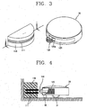
- Figure 3 is a perspective view showing an automatic charging device of an automatically traveling cleaner in accordance with the present invention
- Figure 4 is a partial vertical-sectional view showing the automatic charging device of an automatically traveling cleaner in accordance with the present invention
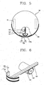
- Figure 5 is a plane view showing a charging terminal unit and a contact sensor unit installed in the automatically traveling cleaner.
- the automatic charging device of an automatically traveling cleaner in accordance with the present invention includes: a charger 110 having a power source terminal 111; a contact sensor unit 120 installed at an automatically traveling cleaner 30 so as to be in contact with the power source terminal 111; a charging terminal unit 130 slidably installed at the automatically traveling cleaner 30 and being selectively contact with the power source terminal 111; and a charging terminal unit driving unit for selectively drawing in and out the charging terminal unit 130.
- An opening 120a is formed at the middle portion of the contact sensor unit 120, through which the charging terminal unit 130 can be drawn in and out.
- the power source terminal 111 is formed in a shape of a circular arc at an outer circumferential surface of the charger 110, and the contact sensor unit 120 is also formed in a shape of a circular arc at an outer circumferential surface of the automatically traveling cleaner 30 so as to correspond to the power source terminal 111.
- a front surface of the charging terminal unit 130 is also formed in a shape of a circular arc so as to correspond to the power source terminal 111.
- the power source terminal 111, the contact sensor unit 120 and the charging terminal unit 130 are formed in the shape of the circular arc, an entering angle of the traveling cleaner 30 becomes wide, and thus, a charging induction time of the traveling cleaner 30 can be much reduced, and charging can be performed easily and quickly.
- the contact sensor unit 130 there can be used a tact switch, an optical sensor using ultrasonic waves or infrared rays, or a magnetic sensor sensing a strength of a magnetic field.
- the charging terminal unit 130 is selectively drawn out, so that when the traveling cleaner 30 advances, it can be prevented from being damaged by possible collision with an object.
- the charging terminal unit 130 is moved in a radial direction of the traveling cleaner 30 through the opening formed at the outer circumferential surface of the traveling cleaner 30.
- the power source terminal 111, the contact sensor unit 120 and the charging terminal are positioned at the same level so that when the charging terminal unit 130 is drawn out to be connected to the power source terminal 111, they can smoothly contact each other.
- Figure 6 is a perspective view showing one example of a charging terminal unit driving unit.
- the charging terminal unit driving unit includes: a rack 141 formed at one side of the charging terminal unit 130, a pinion 142 engaged with the rack 141, and a drive motor 143 for rotating the pinion142.
- the charging terminal unit 130 consists of a charging terminal main body 131 and a charging electrode 132 attached at a front surface of the charging terminal main body 131.
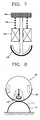
- Figure 7 is a plane view showing another example of the charging terminal unit driving unit.
- the charging terminal unit driving unit includes a moving plate 144 made of a steel material fixed at an end of the charging terminal unit 130, an electromagnet 145 fixed in the automatically traveling cleaner 30 and pulling up the moving plate 144; and an elastic member 146 installed between the moving plate 144 and the electromagnet 145.
- the electromagnet 145 is magnetized to selectively pull up the moving plate 144 to draw the charging terminal unit 130 in and out of the traveling cleaner 30, and at this time, the elastic member 146 allows the charging terminal unit 130 to return to its original position.
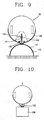
- Figure 8 is a plane view showing a state that the contact sensor unit is in contact with a power source terminal
- Figure 9 is a plane view showing a state that the charging terminal unit is in contact with the power source terminal.
- the traveling cleaner 30 advances to approach the charger 110 according to a known art.
- the contact sensor unit 120 senses that the traveling cleaner 30 is in contact with the power source terminal 111 of the charger 110.
- the drive motor 143 operates to rotate the pinion 142. Then, the charging terminal unit 130 where the rack 141 is formed is drawn out of the traveling cleaner 30 according to the rotation of the pinion 142, so that the charging terminal unit 130 is maintained in a state of contacting the power source terminal 111.
- the charging terminal unit 130 and the power source terminal 111 are electrically connected and the traveling cleaner 30 is charged.
- the traveling cleaner 30 meets an obstacle 200 while approaching the charger 110, the charging terminal unit 130 is drawn out of the traveling cleaner 30 and maintained in a state of contacting the obstacle 200.
- obstacles are mostly non-conductive materials, so the charging terminal unit 130 would not be electrically connected with the obstacle 200.
- the traveling cleaner 30 returns the charging terminal unit 130 to its original position, and moves backward (reversely) to avoid the obstacle 200 and approaches the charger 110 again.
- Reference numeral 32 denotes an auxiliary wheel.
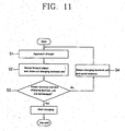
- Figure 11 is a flow chart of an automatic charging method of the automatically traveling cleaner in accordance with the present invention.
- the charging method of the automatically traveling cleaner includes a first step (S1) in which the traveling cleaner approaches the charger; a second step (S2) in which if a forward object is contacted to the contact sensor unit while the traveling cleaner is being approached, the charging terminal unit is drawn out; a third step (S3) in which it is determined whether the forward object is a charger; a fourth step (S4) in which if the charging terminal unit is electrically connected to the forward object, the forward object is recognized as a charger and the traveling cleaner is charged; and a fifth step (S5) in which if the charging terminal unit is not electrically connected with the forward object, the forward object is recognized as an obstacle, the charging terminal unit is returned to its original position, and the traveling cleaner is again approached toward the charger by avoiding the forward object.
- the traveling cleaner In the first step, if a battery capacity is dropped to below a pre-set level while the traveling cleaner performs a cleaning operation, the traveling cleaner approaches toward the charger according to the known art. While the traveling cleaner is proceeding to the charger, it may meet an obstacle or directly approaches the charger without facing the obstacle.
- the charging terminal unit is drawn out of the traveling cleaner through the charging terminal unit driving unit.
- the forward object is a charger or an obstacle.
- the forward object is recognized as a charger and the traveling cleaner is charged. Conversely, if the charging terminal unit is not electrically connected to the forward object, the forward object is recognized as an obstacle, so the charging terminal unit is returned to its original position and then the traveling cleaner is again approached toward the charger by avoiding the forward object.
- the automatic charging device and method of an automatically traveling cleaner in accordance with the present invention have the following advantages.
- the traveling cleaner is prevented from being damaged from collision with an object while being moved forwardly
- the power source terminal, the contact sensor unit and the charging terminal unit are formed in a shape of a circular arc, the entering angle of the traveling cleaner widens, so that the charging induction time can be much reduced and the charging can be performed easily and quickly.
Landscapes
- Engineering & Computer Science (AREA)
- Mechanical Engineering (AREA)
- Robotics (AREA)
- Power Engineering (AREA)
- Charge And Discharge Circuits For Batteries Or The Like (AREA)
- Control Of Position, Course, Altitude, Or Attitude Of Moving Bodies (AREA)
- Electric Propulsion And Braking For Vehicles (AREA)
- Electric Suction Cleaners (AREA)
- Electric Vacuum Cleaner (AREA)
- Secondary Cells (AREA)
- Spinning Or Twisting Of Yarns (AREA)
- Knitting Machines (AREA)
- Vehicle Cleaning, Maintenance, Repair, Refitting, And Outriggers (AREA)
Abstract
Description
- The present invention relates to an automatic charging device and method of an automatically traveling cleaner and, more particularly, to an automatic charging device and method of an automatically traveling cleaner capable of allowing an automatically traveling cleaner to return to a charger for an automatic charging.
- In general, an automatically traveling cleaner is a device having a function of cleaning by sucking dust or the like while going around indoors. The automatically traveling cleaner includes a direction-changing caster formed at one side of the bottom of a round-shaped main body, driving wheels formed at both sides of the other side of the bottom, and a dust sucking opening formed at a front side of the bottom.
- In order to charge a battery installed in the traveling cleaner, a cord installed at a rear side of the traveling cleaner can be connected to a charger, or a charger sensing unit can be mounted at the traveling cleaner so that the traveling cleaner can search the charger and is automatically charged.
- Figure 1 is a schematic plane view showing a construction of an automatic charging device of the automatically traveling cleaner using a light emitting/receiving sensor in accordance with one conventional art.
- As shown in Figure 1, in the automatic charging device of the automatically traveling cleaner using the light emitting/receiving sensor in accordance with the conventional art, a
power source terminal 12 is formed at one side of a charger 11 and alight emitting sensor 13 is installed at the other side thereof. - A
driving wheel 31 is installed at both sides of the bottom of thetraveling cleaner 30, acharging terminal unit 14 is installed at one side of thetraveling cleaner 30 and alight receiving sensor 15 is installed at the other side thereof. - In the automatic charging device of the automatically traveling cleaner using the light emitting/receiving sensor constructed as described above, the
charging terminal unit 14 is in contact with thepower source terminal 13 by moving the automatically travelingcleaner 30 to a predetermined position so that thelight receiving sensor 15 can sense beams radiated from thelight emitting sensor 13. Reference numeral 'W' is a fixed structure such as a wall surface. - Figure 2 is a schematic plane view showing a construction of an automatic charging device of an automatically traveling cleaner using a guide in accordance with another conventional art.
- As shown in Figure 2, the automatic charging device of an automatically traveling cleaner using a guide includes a
power source terminal 22 formed at one side of acharger 21 and aguide 23 installed at the other side of thecharger 21.Driving wheels 31 are installed at both sides of the bottom of thetraveling cleaner 30, a charging terminal unit 24 is formed at one side of thetraveling cleaner 30, and acontact sensor 25 is installed at the other side. θ is an installation angle of the guide, or an entering angle of the traveling cleaner. - In the automatic charging device of the automatically traveling cleaner using the guide as constructed above, when the automatically traveling
cleaner 30 is moved and thecontact sensor 25 comes in contact with theguide 23, thetraveling cleaner 30 is moved forward or backward to allow the charging terminal unit 24 to be in contact with thepower source terminal 22. - However, the automatically traveling cleaner as shown in Figure 1 has a problem that the light receiving sensor may fail to sense beams radiated from the light emitting sensor due to an obstacle or the like, so the automatically traveling cleaner can not be smoothly charged.
- Meanwhile, in the case of the automatically traveling cleaner as shown in Figure 2, the installation angle of the guide installed in the charger is so small that the traveling cleaner has no choice but to enter within the limited angle. This means that the traveling cleaner can hardly approach the charger but also so much time is taken to approach.
- Known automatic charging devices and methods are described in US-A-5,682,640 and US-A-5,440,216.
- Therefore, an object of the present invention is to provide an automatic charging device and method of an automatically traveling cleaner capable of allowing an automatically traveling cleaner to quickly approach a charger by avoiding an obstacle by itself and be charged.
- To achieve these and other advantages and in accordance with the purpose of the present invention, as embodied and broadly described herein, there is provided an automatic charging device for an automatically traveling cleaner including: a charger having a power source terminal; a contact sensor unit installed on said automatically traveling cleaner so as to be in contact with the power source terminal; a charging terminal unit slidably installed on said automatically traveling cleaner and selectively contacting the power source terminal; and a charging terminal unit driving unit for selectively drawing in and out the charging terminal unit.
- To achieve the above objects, there is also provided a method of automatically charging an automatically traveling cleaner, including: a first step in which a traveling cleaner approaches toward a charger; a second step in which a charging terminal unit is extended when a forward object (that is, an object that the traveling cleaner meets in its proceeding) is in contact with a contact sensor unit while the traveling cleaner is being approached; a third step in which it is determined whether the forward object is the charger; a fourth step in which if the charging terminal unit is electrically connected with the forward object, the forward object is recognized as a charger, and the traveling cleaner is charged; and a fifth step in which if the charging terminal unit is not electrically connected with the forward object, the forward object is recognized as an obstacle, the charging terminal unit is returned to its original position, and the traveling cleaner again approaches toward the charger by avoiding the forward object.
- The foregoing and other objects, features, aspects and advantages of the present invention will become more apparent from the following detailed description of the present invention when taken in conjunction with the accompanying drawings.
- The accompanying drawings, which are included to provide a further understanding of the invention and are incorporated in and constitute a part of this specification, illustrate embodiments of the invention and together with the description serve to explain the principles of the invention.
- In the drawings:
- Figure 1 is a schematic plane view showing a construction of an automatic charging device of an automatically traveling cleaner using a light emitting/receiving sensor in accordance with one conventional art;
- Figure 2 is a schematic plane view showing a construction of an automatic charging device of an automatically traveling cleaner using a guide in accordance with another conventional art;
- Figure 3 is a perspective view showing an automatic charging device of an automatically traveling cleaner in accordance with the present invention;
- Figure 4 is a partial vertical-sectional view showing the automatic charging device of an automatically traveling cleaner in accordance with the present invention;
- Figure 5 is a plane view showing a charging terminal unit and a contact sensor unit installed in the automatically traveling cleaner;
- Figure 6 is a perspective view showing one example of a charging terminal unit driving unit;
- Figure 7 is a plane view showing another example of the charging terminal unit driving unit;
- Figure 8 is a plane view showing a state that the contact sensor unit is in contact with a power source terminal;
- Figure 9 is a plane view showing a state that the charging terminal unit is in contact with the power source terminal;
- Figure 10 is a plane view showing a state that the charging terminal unit is in contact with an obstacle; and
- Figure 11 is a flow chart of an automatic charging method of the automatically traveling cleaner in accordance with the present invention.
- Reference will now be made in detail to the preferred embodiments of the present invention, examples of which are illustrated in the accompanying drawings.
- An automatic charging device of an automatically traveling cleaner in accordance with the present invention will now be described with reference to the accompanying drawings.
- Figure 3 is a perspective view showing an automatic charging device of an automatically traveling cleaner in accordance with the present invention, Figure 4 is a partial vertical-sectional view showing the automatic charging device of an automatically traveling cleaner in accordance with the present invention, and Figure 5 is a plane view showing a charging terminal unit and a contact sensor unit installed in the automatically traveling cleaner.
- As illustrated, the automatic charging device of an automatically traveling cleaner in accordance with the present invention includes: a
charger 110 having apower source terminal 111; acontact sensor unit 120 installed at an automatically travelingcleaner 30 so as to be in contact with thepower source terminal 111; acharging terminal unit 130 slidably installed at the automatically travelingcleaner 30 and being selectively contact with thepower source terminal 111; and a charging terminal unit driving unit for selectively drawing in and out thecharging terminal unit 130. - An opening 120a is formed at the middle portion of the
contact sensor unit 120, through which thecharging terminal unit 130 can be drawn in and out. - The
power source terminal 111 is formed in a shape of a circular arc at an outer circumferential surface of thecharger 110, and thecontact sensor unit 120 is also formed in a shape of a circular arc at an outer circumferential surface of the automatically travelingcleaner 30 so as to correspond to thepower source terminal 111. In addition, a front surface of thecharging terminal unit 130 is also formed in a shape of a circular arc so as to correspond to thepower source terminal 111. - Since the
power source terminal 111, thecontact sensor unit 120 and thecharging terminal unit 130 are formed in the shape of the circular arc, an entering angle of thetraveling cleaner 30 becomes wide, and thus, a charging induction time of thetraveling cleaner 30 can be much reduced, and charging can be performed easily and quickly. - As the
contact sensor unit 130, there can be used a tact switch, an optical sensor using ultrasonic waves or infrared rays, or a magnetic sensor sensing a strength of a magnetic field. - Installed in the
traveling cleaner 30, thecharging terminal unit 130 is selectively drawn out, so that when the traveling cleaner 30 advances, it can be prevented from being damaged by possible collision with an object. - The
charging terminal unit 130 is moved in a radial direction of thetraveling cleaner 30 through the opening formed at the outer circumferential surface of thetraveling cleaner 30. - Preferably, the
power source terminal 111, thecontact sensor unit 120 and the charging terminal are positioned at the same level so that when thecharging terminal unit 130 is drawn out to be connected to thepower source terminal 111, they can smoothly contact each other. - Figure 6 is a perspective view showing one example of a charging terminal unit driving unit.
- As illustrated, the charging terminal unit driving unit includes: a
rack 141 formed at one side of thecharging terminal unit 130, apinion 142 engaged with therack 141, and adrive motor 143 for rotating the pinion142. - The
charging terminal unit 130 consists of a charging terminalmain body 131 and acharging electrode 132 attached at a front surface of the charging terminalmain body 131. - Figure 7 is a plane view showing another example of the charging terminal unit driving unit.
- As illustrated, the charging terminal unit driving unit includes a moving
plate 144 made of a steel material fixed at an end of thecharging terminal unit 130, anelectromagnet 145 fixed in the automatically travelingcleaner 30 and pulling up the movingplate 144; and anelastic member 146 installed between the movingplate 144 and theelectromagnet 145. - The
electromagnet 145 is magnetized to selectively pull up the movingplate 144 to draw thecharging terminal unit 130 in and out of thetraveling cleaner 30, and at this time, theelastic member 146 allows thecharging terminal unit 130 to return to its original position. - Figure 8 is a plane view showing a state that the contact sensor unit is in contact with a power source terminal, and Figure 9 is a plane view showing a state that the charging terminal unit is in contact with the power source terminal.
- First, with reference to Figure 8, the
traveling cleaner 30 advances to approach thecharger 110 according to a known art. At this time, thecontact sensor unit 120 senses that thetraveling cleaner 30 is in contact with thepower source terminal 111 of thecharger 110. - In this state, as shown in Figure 9, the
drive motor 143 operates to rotate thepinion 142. Then, thecharging terminal unit 130 where therack 141 is formed is drawn out of thetraveling cleaner 30 according to the rotation of thepinion 142, so that thecharging terminal unit 130 is maintained in a state of contacting thepower source terminal 111. - In this state, the charging
terminal unit 130 and thepower source terminal 111 are electrically connected and the traveling cleaner 30 is charged. - Meanwhile, as shown in Figure 10, if the traveling cleaner 30 meets an
obstacle 200 while approaching thecharger 110, the chargingterminal unit 130 is drawn out of the traveling cleaner 30 and maintained in a state of contacting theobstacle 200. In this case, obstacles are mostly non-conductive materials, so the chargingterminal unit 130 would not be electrically connected with theobstacle 200. - At this time, the traveling cleaner 30 returns the charging
terminal unit 130 to its original position, and moves backward (reversely) to avoid theobstacle 200 and approaches thecharger 110 again.Reference numeral 32 denotes an auxiliary wheel. - The charging method of the automatically traveling cleaner of the present invention will now be described in detail with reference to Figure 11.
- Figure 11 is a flow chart of an automatic charging method of the automatically traveling cleaner in accordance with the present invention.
- As illustrated, the charging method of the automatically traveling cleaner includes a first step (S1) in which the traveling cleaner approaches the charger; a second step (S2) in which if a forward object is contacted to the contact sensor unit while the traveling cleaner is being approached, the charging terminal unit is drawn out; a third step (S3) in which it is determined whether the forward object is a charger; a fourth step (S4) in which if the charging terminal unit is electrically connected to the forward object, the forward object is recognized as a charger and the traveling cleaner is charged; and a fifth step (S5) in which if the charging terminal unit is not electrically connected with the forward object, the forward object is recognized as an obstacle, the charging terminal unit is returned to its original position, and the traveling cleaner is again approached toward the charger by avoiding the forward object.
- In the first step, if a battery capacity is dropped to below a pre-set level while the traveling cleaner performs a cleaning operation, the traveling cleaner approaches toward the charger according to the known art. While the traveling cleaner is proceeding to the charger, it may meet an obstacle or directly approaches the charger without facing the obstacle.
- In the second step, if the contact sensor unit contacts the forward object while the traveling cleaner is being approached, the charging terminal unit is drawn out of the traveling cleaner through the charging terminal unit driving unit.
- In the third step, it is determined whether the forward object is a charger or an obstacle.
- In the fourth and fifth steps, if the charging terminal unit is electrically connected to the forward object, the forward object is recognized as a charger and the traveling cleaner is charged. Conversely, if the charging terminal unit is not electrically connected to the forward object, the forward object is recognized as an obstacle, so the charging terminal unit is returned to its original position and then the traveling cleaner is again approached toward the charger by avoiding the forward object.
- As so far described, the automatic charging device and method of an automatically traveling cleaner in accordance with the present invention have the following advantages.
- That is, first, since the charging terminal unit is installed inside the traveling cleaner and selectively drawn out, the traveling cleaner is prevented from being damaged from collision with an object while being moved forwardly
- In addition, because the power source terminal, the contact sensor unit and the charging terminal unit are formed in a shape of a circular arc, the entering angle of the traveling cleaner widens, so that the charging induction time can be much reduced and the charging can be performed easily and quickly.
- As the present invention may be embodied in several forms without departing from the spirit or essential characteristics thereof, it should also be understood that the above-described embodiments are not limited by any of the details of the foregoing description, unless otherwise specified, but rather should be construed broadly within its spirit and scope as defined in the appended claims, and therefore all changes and modifications that fall within the metes and bounds of the claims, or equivalence of such metes and bounds are therefore intended to be embraced by the appended claims.
Claims (10)
- An automatic charging device for an automatically traveling cleaner (30) comprising:a charger (110) having a power source terminal (111);a contact sensor unit (120) installed on said automatically traveling cleaner (30) so as to be in contact with the power source terminal (111);a charging terminal unit (130) slidably installed on said automatically traveling cleaner (30) and selectively contacting the power source terminal (111); anda charging terminal unit driving unit for selectively drawing in and out the charging terminal unit (130).
- The device of claim 1, wherein an opening is formed at the middle portion of the contact sensor unit, to allow the charging terminal unit to be drawn in and out therethrough.
- The device of claim 1, wherein the power source unit is formed in a shape of a circular arc at an outer circumferential surface of the charger, and the contact sensor unit is also formed in a shape of a circular arc at an outer circumferential surface of the automatically traveling cleaner so as to correspond to the power source terminal.
- The device of claim 3, wherein the power source terminal and the contact sensor unit are positioned at the same level.
- The device of claim 3, wherein a front surface of the charging terminal unit has a shape of a circular arc in order to correspond to the power source terminal.
- The device of claim 1, wherein the charging terminal unit includes:a charging terminal main body; anda charging electrode attached at a front surface of the charging terminal main body.
- The device of claim 1, wherein the charging terminal unit is moved in a radial direction of the traveling cleaner.
- The device of claim 1, wherein the charging terminal unit driving unit comprises:a rack formed at one side of the charging terminal unit;a pinion engaged with the rack; anda drive motor for rotating the pinion.
- The device of claim 1, wherein the charging terminal unit driving unit comprises:a moving plate made of a steel material and fixed at an end of the charging terminal unit;an electromagnet fixed inside the automatically traveling cleaner and pulling up the moving plate; andan elastic member installed between the moving plate and the electromagnet.
- A method of automatically charging an automatically traveling cleaner, comprising:a first step (S1) in which a traveling cleaner approaches toward a chargera second step (S2) in which a charging terminal unit is extended, when a forward object is in contact with a contact sensor unit (120) while the traveling cleaner (30) is being approached;a third step (S3) in which it is determined whether the forward object is the charger;a fourth step (S4) in which if the charging terminal unit (130) is electrically connected with the forward object, the forward object is recognized as a charger, and the traveling cleaner (30) is charged; anda fifth step (S5) in which if the charging terminal unit (130) is not electrically connected with the forward object, the forward object is recognized as an obstacle, the charging terminal unit (130) is returned to its original position, and the traveling cleaner (30) again approaches toward the charger by avoiding the forward object.
Applications Claiming Priority (2)
| Application Number | Priority Date | Filing Date | Title |
|---|---|---|---|
| KR2002080836 | 2002-12-17 | ||
| KR10-2002-0080836A KR100480036B1 (en) | 2002-12-17 | 2002-12-17 | Automatic charging apparatus method and method for automatic running vacuum cleaner |
Publications (3)
| Publication Number | Publication Date |
|---|---|
| EP1430826A2 EP1430826A2 (en) | 2004-06-23 |
| EP1430826A3 EP1430826A3 (en) | 2006-03-22 |
| EP1430826B1 true EP1430826B1 (en) | 2007-05-09 |
Family
ID=32388333
Family Applications (1)
| Application Number | Title | Priority Date | Filing Date |
|---|---|---|---|
| EP03027605A Expired - Lifetime EP1430826B1 (en) | 2002-12-17 | 2003-12-02 | Automatic charging device for an automatically travelling cleaner and method of automatically charging an automatically travelling cleaner |
Country Status (8)
| Country | Link |
|---|---|
| US (1) | US7202630B2 (en) |
| EP (1) | EP1430826B1 (en) |
| JP (1) | JP3951187B2 (en) |
| KR (1) | KR100480036B1 (en) |
| CN (1) | CN1285317C (en) |
| AT (1) | ATE361696T1 (en) |
| DE (1) | DE60313723T2 (en) |
| RU (1) | RU2260369C2 (en) |
Families Citing this family (61)
| Publication number | Priority date | Publication date | Assignee | Title |
|---|---|---|---|---|
| WO2005074362A2 (en) | 2004-02-03 | 2005-08-18 | F. Robotics Aquisitions Ltd. | Robot docking station |
| JP4786881B2 (en) * | 2004-06-10 | 2011-10-05 | 旭化成エレクトロニクス株式会社 | Vacuum cleaner and iron |
| KR100641113B1 (en) * | 2004-07-30 | 2006-11-02 | 엘지전자 주식회사 | Mobile robot and its movement control method |
| EP1805863B1 (en) * | 2004-10-18 | 2013-06-26 | Black & Decker, Inc. | Cordless power system |
| KR20060112312A (en) | 2005-04-25 | 2006-11-01 | 엘지전자 주식회사 | Power saving control device and method for robot cleaner |
| KR101290095B1 (en) * | 2006-04-26 | 2013-08-01 | 삼성전자주식회사 | Robot cleaner system having robot cleaner and docking station |
| KR100758038B1 (en) * | 2006-11-22 | 2007-09-11 | 삼성광주전자 주식회사 | How to charge the robot cleaner |
| CN101211186B (en) * | 2006-12-29 | 2010-12-08 | 财团法人工业技术研究院 | Method for returning movable device to service station and movable device service system |
| DE102007036228B4 (en) | 2007-08-02 | 2013-10-10 | BSH Bosch und Siemens Hausgeräte GmbH | Method and system for ensuring a connection between a mobile device and a stationary device, in particular between an accumulator-powered dust collection robot and a battery charging station |
| DE102007036173B4 (en) | 2007-08-02 | 2012-01-26 | BSH Bosch und Siemens Hausgeräte GmbH | Housing for a fixed station of a robot system formed in particular by a dust collection robot system |
| DE102007036172B4 (en) | 2007-08-02 | 2012-01-19 | BSH Bosch und Siemens Hausgeräte GmbH | Housing for a fixed station of a robot system formed in particular by a dust collection robot system |
| DE102007036152B4 (en) | 2007-08-02 | 2011-06-16 | BSH Bosch und Siemens Hausgeräte GmbH | Housing for a fixed station of a robot system formed in particular by a dust collection robot system |
| JP5301255B2 (en) * | 2007-12-17 | 2013-09-25 | フォルヴェルク・ウント・ツェーオー、インターホールディング・ゲーエムベーハー | Dust collector for floor cleaning |
| CN101774169A (en) * | 2009-01-08 | 2010-07-14 | 鸿富锦精密工业(深圳)有限公司 | robot |
| DE102009023066A1 (en) * | 2009-04-01 | 2010-10-07 | Vorwerk & Co. Interholding Gmbh | Automatically movable device, in particular self-propelled ground dust collecting device |
| GB0909148D0 (en) | 2009-05-28 | 2009-07-01 | F Robotics Acquisitions Ltd | Localisation system |
| JP5496553B2 (en) * | 2009-06-15 | 2014-05-21 | 三洋電機株式会社 | Charging stand |
| EP2571344B1 (en) | 2010-05-19 | 2017-09-13 | Husqvarna AB | Effective charging by multiple contact points |
| CN102314181B (en) * | 2010-07-08 | 2013-09-18 | 美新半导体(无锡)有限公司 | Direction control system and application thereof |
| TWM412591U (en) * | 2011-03-23 | 2011-09-21 | Micro Star Int Co Ltd | Electrodes storage structure for cleaning robot |
| US9045049B2 (en) * | 2011-08-28 | 2015-06-02 | Irobot Corporation | System and method for in situ charging of a remote vehicle |
| JP5942530B2 (en) * | 2012-03-28 | 2016-06-29 | カシオ計算機株式会社 | Non-contact charging system and electronic equipment |
| ES2610755T3 (en) | 2012-08-27 | 2017-05-03 | Aktiebolaget Electrolux | Robot positioning system |
| JP5954214B2 (en) * | 2013-02-18 | 2016-07-20 | 株式会社ナカヨ | Power receiving device |
| EP2986192B1 (en) | 2013-04-15 | 2021-03-31 | Aktiebolaget Electrolux | Robotic vacuum cleaner |
| CN105101855A (en) | 2013-04-15 | 2015-11-25 | 伊莱克斯公司 | Robotic vacuum cleaner with sticking out side brushes |
| KR102099495B1 (en) | 2013-12-19 | 2020-04-09 | 에이비 엘렉트로룩스 | Sensing climb of obstacle of a robotic cleaning device |
| CN105792721B (en) | 2013-12-19 | 2020-07-21 | 伊莱克斯公司 | Robotic vacuum cleaner with side brush moving in spiral pattern |
| WO2015090402A1 (en) | 2013-12-19 | 2015-06-25 | Aktiebolaget Electrolux | Robotic cleaning device with perimeter recording function |
| JP6638987B2 (en) | 2013-12-19 | 2020-02-05 | アクチエボラゲット エレクトロルックス | Adaptive speed control of rotating side brush |
| EP3082537B1 (en) | 2013-12-19 | 2020-11-18 | Aktiebolaget Electrolux | Robotic cleaning device and method for landmark recognition |
| CN105849660B (en) | 2013-12-19 | 2020-05-08 | 伊莱克斯公司 | Robotic cleaning device |
| EP3084539B1 (en) | 2013-12-19 | 2019-02-20 | Aktiebolaget Electrolux | Prioritizing cleaning areas |
| KR102116595B1 (en) | 2013-12-20 | 2020-06-05 | 에이비 엘렉트로룩스 | Dust container |
| DE102014212427A1 (en) * | 2014-06-27 | 2016-01-14 | Robert Bosch Gmbh | Service robot system |
| WO2016005012A1 (en) | 2014-07-10 | 2016-01-14 | Aktiebolaget Electrolux | Method for detecting a measurement error in a robotic cleaning device |
| JP6443897B2 (en) | 2014-09-08 | 2018-12-26 | アクチエボラゲット エレクトロルックス | Robot vacuum cleaner |
| EP3190938A1 (en) | 2014-09-08 | 2017-07-19 | Aktiebolaget Electrolux | Robotic vacuum cleaner |
| EP3230814B1 (en) | 2014-12-10 | 2021-02-17 | Aktiebolaget Electrolux | Using laser sensor for floor type detection |
| CN107072454A (en) | 2014-12-12 | 2017-08-18 | 伊莱克斯公司 | Side brushes and robot vacuums |
| JP6532530B2 (en) | 2014-12-16 | 2019-06-19 | アクチエボラゲット エレクトロルックス | How to clean a robot vacuum cleaner |
| KR102339531B1 (en) | 2014-12-16 | 2021-12-16 | 에이비 엘렉트로룩스 | Experience-based roadmap for a robotic cleaning device |
| US11099554B2 (en) | 2015-04-17 | 2021-08-24 | Aktiebolaget Electrolux | Robotic cleaning device and a method of controlling the robotic cleaning device |
| USD760649S1 (en) | 2015-06-22 | 2016-07-05 | Mtd Products Inc | Docking station |
| WO2017036532A1 (en) | 2015-09-03 | 2017-03-09 | Aktiebolaget Electrolux | System of robotic cleaning devices |
| FR3043501B1 (en) * | 2015-11-09 | 2017-12-15 | Wolf Outils | ELECTRIC LOADING SYSTEM OF AN AUTONOMOUS ENGINE |
| ES2780179T3 (en) | 2015-11-09 | 2020-08-24 | ETESIA (Société par Actions Simplifiée) | Electric charging system of an autonomous machine |
| CN105361817A (en) * | 2015-11-17 | 2016-03-02 | 深圳市银星智能科技股份有限公司 | Automatic docking system of robot |
| CN108603935A (en) | 2016-03-15 | 2018-09-28 | 伊莱克斯公司 | The method that robotic cleaning device and robotic cleaning device carry out cliff detection |
| WO2017190784A1 (en) * | 2016-05-04 | 2017-11-09 | Alfred Kärcher Gmbh & Co. Kg | Floor treatment system |
| CN109068908B (en) | 2016-05-11 | 2021-05-11 | 伊莱克斯公司 | Robotic Cleaning Equipment |
| CN106026321B (en) * | 2016-07-04 | 2018-12-07 | 西安清眸电子科技有限公司 | A kind of automatic charge device and method from mobile device |
| JP6565869B2 (en) * | 2016-11-08 | 2019-08-28 | トヨタ自動車株式会社 | Autonomous mobile body and control program for autonomous mobile body |
| JP7243967B2 (en) | 2017-06-02 | 2023-03-22 | アクチエボラゲット エレクトロルックス | Method for Detecting Level Differences on a Surface in Front of a Robotic Cleaning Device |
| JP6989210B2 (en) | 2017-09-26 | 2022-01-05 | アクチエボラゲット エレクトロルックス | Controlling the movement of robot cleaning devices |
| CN108433640B (en) * | 2018-04-13 | 2021-07-09 | 苏州爱普电器有限公司 | Rechargeable Surface Cleaning System |
| CN110974097A (en) * | 2019-12-06 | 2020-04-10 | 苏州高之仙自动化科技有限公司 | Workstation and cleaning robot used with it |
| USD1032509S1 (en) | 2021-04-23 | 2024-06-25 | Mtd Products Inc | Docking station |
| CN115553674B (en) * | 2022-09-16 | 2025-09-30 | 科沃斯机器人股份有限公司 | Cleaning base station, cleaning equipment, cleaning system and charging device |
| CN116520738A (en) * | 2023-04-14 | 2023-08-01 | 无锡小天鹅电器有限公司 | Intelligent equipment, control method and device thereof, storage medium and intelligent system |
| KR102848033B1 (en) * | 2023-10-23 | 2025-08-20 | 현대무벡스 주식회사 | Agv charging system |
Family Cites Families (15)
| Publication number | Priority date | Publication date | Assignee | Title |
|---|---|---|---|---|
| JPH0437740Y2 (en) * | 1987-07-31 | 1992-09-04 | ||
| US5109566A (en) * | 1990-06-28 | 1992-05-05 | Matsushita Electric Industrial Co., Ltd. | Self-running cleaning apparatus |
| JP3301089B2 (en) * | 1991-09-03 | 2002-07-15 | 松下電器産業株式会社 | Mobile work robot |
| US5462439A (en) * | 1993-04-19 | 1995-10-31 | Keith; Arlie L. | Charging batteries of electric vehicles |
| JP2833409B2 (en) * | 1993-04-26 | 1998-12-09 | 日立電線株式会社 | Contact current supply device for battery charging on mobile vehicles |
| US5440216A (en) * | 1993-06-08 | 1995-08-08 | Samsung Electronics Co., Ltd. | Robot cleaner |
| DE4344563C1 (en) * | 1993-12-24 | 1994-12-08 | Daimler Benz Ag | Battery charger for an electric vehicle |
| KR970000328Y1 (en) * | 1994-03-31 | 1997-01-16 | 삼성전자 주식회사 | Power supply apparatus for automatic vacuum cleaner |
| US5634237A (en) * | 1995-03-29 | 1997-06-03 | Paranjpe; Ajit P. | Self-guided, self-propelled, convertible cleaning apparatus |
| KR200155821Y1 (en) * | 1997-05-12 | 1999-10-01 | 최진호 | Remote control vacuum cleaner |
| AU1327899A (en) * | 1997-11-27 | 1999-06-16 | Solar & Robotics | Improvements to mobile robots and their control system |
| JP2001346743A (en) * | 2000-06-12 | 2001-12-18 | Sanyo Electric Co Ltd | Vacuum cleaner |
| JP2002268746A (en) * | 2001-03-12 | 2002-09-20 | Canon Inc | Mobile robot apparatus, self-charging method for mobile robot apparatus, and medium providing control program |
| AU767561B2 (en) * | 2001-04-18 | 2003-11-13 | Samsung Kwangju Electronics Co., Ltd. | Robot cleaner, system employing the same and method for reconnecting to external recharging device |
| GB2407652B (en) * | 2003-02-06 | 2005-07-06 | Samsung Kwangju Electronics Co | Robot system having external recharging apparatus and method for docking robot with external recharging apparatus |
-
2002
- 2002-12-17 KR KR10-2002-0080836A patent/KR100480036B1/en not_active Expired - Fee Related
-
2003
- 2003-12-02 AT AT03027605T patent/ATE361696T1/en not_active IP Right Cessation
- 2003-12-02 EP EP03027605A patent/EP1430826B1/en not_active Expired - Lifetime
- 2003-12-02 DE DE60313723T patent/DE60313723T2/en not_active Expired - Lifetime
- 2003-12-02 RU RU2003134823/12A patent/RU2260369C2/en not_active IP Right Cessation
- 2003-12-09 JP JP2003410298A patent/JP3951187B2/en not_active Expired - Fee Related
- 2003-12-09 CN CNB2003101184080A patent/CN1285317C/en not_active Expired - Fee Related
- 2003-12-17 US US10/740,109 patent/US7202630B2/en not_active Expired - Fee Related
Also Published As
| Publication number | Publication date |
|---|---|
| RU2003134823A (en) | 2005-05-20 |
| US7202630B2 (en) | 2007-04-10 |
| RU2260369C2 (en) | 2005-09-20 |
| DE60313723T2 (en) | 2007-09-06 |
| KR100480036B1 (en) | 2005-03-31 |
| US20040130290A1 (en) | 2004-07-08 |
| EP1430826A2 (en) | 2004-06-23 |
| JP2004201493A (en) | 2004-07-15 |
| ATE361696T1 (en) | 2007-06-15 |
| JP3951187B2 (en) | 2007-08-01 |
| CN1507828A (en) | 2004-06-30 |
| EP1430826A3 (en) | 2006-03-22 |
| DE60313723D1 (en) | 2007-06-21 |
| KR20040054114A (en) | 2004-06-25 |
| CN1285317C (en) | 2006-11-22 |
Similar Documents
| Publication | Publication Date | Title |
|---|---|---|
| EP1430826B1 (en) | Automatic charging device for an automatically travelling cleaner and method of automatically charging an automatically travelling cleaner | |
| JP3006986B2 (en) | Robot vacuum cleaner | |
| JP2846835B2 (en) | Charge induction device and method for robot vacuum cleaner | |
| TWI689801B (en) | Autonomous mobile robot and its pile seeking method, control device and intelligent cleaning system | |
| US8476867B2 (en) | Robot battery charging station | |
| US9340116B2 (en) | Self-propelled electronic device | |
| US20080174268A1 (en) | Automatic charging apparatus of autonomous mobile robot and automatic charging method using the same | |
| US20040111827A1 (en) | Brush of cleaner | |
| US9089249B2 (en) | Direction device and operation system utilizing the same | |
| EP4254117B1 (en) | Self-moving robot charging systems and self-moving robot charging method | |
| CN102044888A (en) | Automatic charging system and method | |
| GB2313190A (en) | Navigation sensor | |
| JP7717289B2 (en) | Automatic Cleaning Device | |
| KR200366079Y1 (en) | Charging device for Robot vacuum cleaner | |
| JP2701414B2 (en) | Self-propelled vacuum cleaner | |
| KR970000583B1 (en) | How to induce filling of robot cleaner | |
| AU2022433726B2 (en) | Automatic cleaning apparatus. | |
| JP2782926B2 (en) | Self-propelled vacuum cleaner | |
| JP2007156884A (en) | Self-propelled vacuum cleaner system | |
| JP2594048B2 (en) | Mobile work vehicle with code reel | |
| JP2594047B2 (en) | Mobile work vehicle with code reel | |
| JP2594049B2 (en) | Mobile work vehicle with code reel | |
| JPH1023610A (en) | Micro robot | |
| JP2000288999A (en) | Micro robot |
Legal Events
| Date | Code | Title | Description |
|---|---|---|---|
| PUAI | Public reference made under article 153(3) epc to a published international application that has entered the european phase |
Free format text: ORIGINAL CODE: 0009012 |
|
| 17P | Request for examination filed |
Effective date: 20031202 |
|
| AK | Designated contracting states |
Kind code of ref document: A2 Designated state(s): AT BE BG CH CY CZ DE DK EE ES FI FR GB GR HU IE IT LI LU MC NL PT RO SE SI SK TR |
|
| AX | Request for extension of the european patent |
Extension state: AL LT LV MK |
|
| PUAL | Search report despatched |
Free format text: ORIGINAL CODE: 0009013 |
|
| AK | Designated contracting states |
Kind code of ref document: A3 Designated state(s): AT BE BG CH CY CZ DE DK EE ES FI FR GB GR HU IE IT LI LU MC NL PT RO SE SI SK TR |
|
| AX | Request for extension of the european patent |
Extension state: AL LT LV MK |
|
| GRAP | Despatch of communication of intention to grant a patent |
Free format text: ORIGINAL CODE: EPIDOSNIGR1 |
|
| AKX | Designation fees paid |
Designated state(s): AT BE BG CH CY CZ DE DK EE ES FI FR GB GR HU IE IT LI LU MC NL PT RO SE SI SK TR |
|
| GRAS | Grant fee paid |
Free format text: ORIGINAL CODE: EPIDOSNIGR3 |
|
| GRAA | (expected) grant |
Free format text: ORIGINAL CODE: 0009210 |
|
| AK | Designated contracting states |
Kind code of ref document: B1 Designated state(s): AT BE BG CH CY CZ DE DK EE ES FI FR GB GR HU IE IT LI LU MC NL PT RO SE SI SK TR |
|
| PG25 | Lapsed in a contracting state [announced via postgrant information from national office to epo] |
Ref country code: FI Free format text: LAPSE BECAUSE OF FAILURE TO SUBMIT A TRANSLATION OF THE DESCRIPTION OR TO PAY THE FEE WITHIN THE PRESCRIBED TIME-LIMIT Effective date: 20070509 Ref country code: LI Free format text: LAPSE BECAUSE OF FAILURE TO SUBMIT A TRANSLATION OF THE DESCRIPTION OR TO PAY THE FEE WITHIN THE PRESCRIBED TIME-LIMIT Effective date: 20070509 Ref country code: CH Free format text: LAPSE BECAUSE OF FAILURE TO SUBMIT A TRANSLATION OF THE DESCRIPTION OR TO PAY THE FEE WITHIN THE PRESCRIBED TIME-LIMIT Effective date: 20070509 |
|
| REG | Reference to a national code |
Ref country code: GB Ref legal event code: FG4D |
|
| RTI1 | Title (correction) |
Free format text: AUTOMATIC CHARGING DEVICE FOR AN AUTOMATICALLY TRAVELLING CLEANER AND METHOD OF AUTOMATICALLY CHARGING AN AUTOMATICALLY TRAVELLING CLEANER |
|
| REG | Reference to a national code |
Ref country code: CH Ref legal event code: EP |
|
| REG | Reference to a national code |
Ref country code: IE Ref legal event code: FG4D |
|
| REF | Corresponds to: |
Ref document number: 60313723 Country of ref document: DE Date of ref document: 20070621 Kind code of ref document: P |
|
| PG25 | Lapsed in a contracting state [announced via postgrant information from national office to epo] |
Ref country code: SE Free format text: LAPSE BECAUSE OF FAILURE TO SUBMIT A TRANSLATION OF THE DESCRIPTION OR TO PAY THE FEE WITHIN THE PRESCRIBED TIME-LIMIT Effective date: 20070809 |
|
| PG25 | Lapsed in a contracting state [announced via postgrant information from national office to epo] |
Ref country code: ES Free format text: LAPSE BECAUSE OF FAILURE TO SUBMIT A TRANSLATION OF THE DESCRIPTION OR TO PAY THE FEE WITHIN THE PRESCRIBED TIME-LIMIT Effective date: 20070820 |
|
| ET | Fr: translation filed | ||
| REG | Reference to a national code |
Ref country code: CH Ref legal event code: PL |
|
| PG25 | Lapsed in a contracting state [announced via postgrant information from national office to epo] |
Ref country code: AT Free format text: LAPSE BECAUSE OF FAILURE TO SUBMIT A TRANSLATION OF THE DESCRIPTION OR TO PAY THE FEE WITHIN THE PRESCRIBED TIME-LIMIT Effective date: 20070509 |
|
| PG25 | Lapsed in a contracting state [announced via postgrant information from national office to epo] |
Ref country code: BE Free format text: LAPSE BECAUSE OF FAILURE TO SUBMIT A TRANSLATION OF THE DESCRIPTION OR TO PAY THE FEE WITHIN THE PRESCRIBED TIME-LIMIT Effective date: 20070509 |
|
| PG25 | Lapsed in a contracting state [announced via postgrant information from national office to epo] |
Ref country code: DK Free format text: LAPSE BECAUSE OF FAILURE TO SUBMIT A TRANSLATION OF THE DESCRIPTION OR TO PAY THE FEE WITHIN THE PRESCRIBED TIME-LIMIT Effective date: 20070509 Ref country code: SI Free format text: LAPSE BECAUSE OF FAILURE TO SUBMIT A TRANSLATION OF THE DESCRIPTION OR TO PAY THE FEE WITHIN THE PRESCRIBED TIME-LIMIT Effective date: 20070509 Ref country code: PT Free format text: LAPSE BECAUSE OF FAILURE TO SUBMIT A TRANSLATION OF THE DESCRIPTION OR TO PAY THE FEE WITHIN THE PRESCRIBED TIME-LIMIT Effective date: 20071009 Ref country code: CZ Free format text: LAPSE BECAUSE OF FAILURE TO SUBMIT A TRANSLATION OF THE DESCRIPTION OR TO PAY THE FEE WITHIN THE PRESCRIBED TIME-LIMIT Effective date: 20070509 Ref country code: BG Free format text: LAPSE BECAUSE OF FAILURE TO SUBMIT A TRANSLATION OF THE DESCRIPTION OR TO PAY THE FEE WITHIN THE PRESCRIBED TIME-LIMIT Effective date: 20070809 |
|
| PG25 | Lapsed in a contracting state [announced via postgrant information from national office to epo] |
Ref country code: SK Free format text: LAPSE BECAUSE OF FAILURE TO SUBMIT A TRANSLATION OF THE DESCRIPTION OR TO PAY THE FEE WITHIN THE PRESCRIBED TIME-LIMIT Effective date: 20070509 |
|
| PLBE | No opposition filed within time limit |
Free format text: ORIGINAL CODE: 0009261 |
|
| STAA | Information on the status of an ep patent application or granted ep patent |
Free format text: STATUS: NO OPPOSITION FILED WITHIN TIME LIMIT |
|
| 26N | No opposition filed |
Effective date: 20080212 |
|
| PG25 | Lapsed in a contracting state [announced via postgrant information from national office to epo] |
Ref country code: GR Free format text: LAPSE BECAUSE OF FAILURE TO SUBMIT A TRANSLATION OF THE DESCRIPTION OR TO PAY THE FEE WITHIN THE PRESCRIBED TIME-LIMIT Effective date: 20070810 |
|
| PG25 | Lapsed in a contracting state [announced via postgrant information from national office to epo] |
Ref country code: RO Free format text: LAPSE BECAUSE OF FAILURE TO SUBMIT A TRANSLATION OF THE DESCRIPTION OR TO PAY THE FEE WITHIN THE PRESCRIBED TIME-LIMIT Effective date: 20070509 |
|
| PG25 | Lapsed in a contracting state [announced via postgrant information from national office to epo] |
Ref country code: MC Free format text: LAPSE BECAUSE OF NON-PAYMENT OF DUE FEES Effective date: 20071231 |
|
| PG25 | Lapsed in a contracting state [announced via postgrant information from national office to epo] |
Ref country code: IE Free format text: LAPSE BECAUSE OF NON-PAYMENT OF DUE FEES Effective date: 20071203 |
|
| PG25 | Lapsed in a contracting state [announced via postgrant information from national office to epo] |
Ref country code: EE Free format text: LAPSE BECAUSE OF FAILURE TO SUBMIT A TRANSLATION OF THE DESCRIPTION OR TO PAY THE FEE WITHIN THE PRESCRIBED TIME-LIMIT Effective date: 20070509 |
|
| PG25 | Lapsed in a contracting state [announced via postgrant information from national office to epo] |
Ref country code: CY Free format text: LAPSE BECAUSE OF FAILURE TO SUBMIT A TRANSLATION OF THE DESCRIPTION OR TO PAY THE FEE WITHIN THE PRESCRIBED TIME-LIMIT Effective date: 20070509 |
|
| PG25 | Lapsed in a contracting state [announced via postgrant information from national office to epo] |
Ref country code: LU Free format text: LAPSE BECAUSE OF NON-PAYMENT OF DUE FEES Effective date: 20071202 |
|
| PG25 | Lapsed in a contracting state [announced via postgrant information from national office to epo] |
Ref country code: HU Free format text: LAPSE BECAUSE OF FAILURE TO SUBMIT A TRANSLATION OF THE DESCRIPTION OR TO PAY THE FEE WITHIN THE PRESCRIBED TIME-LIMIT Effective date: 20071110 Ref country code: TR Free format text: LAPSE BECAUSE OF FAILURE TO SUBMIT A TRANSLATION OF THE DESCRIPTION OR TO PAY THE FEE WITHIN THE PRESCRIBED TIME-LIMIT Effective date: 20070509 |
|
| PGFP | Annual fee paid to national office [announced via postgrant information from national office to epo] |
Ref country code: DE Payment date: 20131113 Year of fee payment: 11 Ref country code: GB Payment date: 20131112 Year of fee payment: 11 |
|
| PGFP | Annual fee paid to national office [announced via postgrant information from national office to epo] |
Ref country code: IT Payment date: 20131211 Year of fee payment: 11 Ref country code: NL Payment date: 20131112 Year of fee payment: 11 |
|
| PGFP | Annual fee paid to national office [announced via postgrant information from national office to epo] |
Ref country code: FR Payment date: 20131115 Year of fee payment: 11 |
|
| REG | Reference to a national code |
Ref country code: DE Ref legal event code: R119 Ref document number: 60313723 Country of ref document: DE |
|
| REG | Reference to a national code |
Ref country code: NL Ref legal event code: V1 Effective date: 20150701 |
|
| REG | Reference to a national code |
Ref country code: NL Ref legal event code: V1 Effective date: 20150701 |
|
| GBPC | Gb: european patent ceased through non-payment of renewal fee |
Effective date: 20141202 |
|
| REG | Reference to a national code |
Ref country code: FR Ref legal event code: ST Effective date: 20150831 |
|
| PG25 | Lapsed in a contracting state [announced via postgrant information from national office to epo] |
Ref country code: NL Free format text: LAPSE BECAUSE OF NON-PAYMENT OF DUE FEES Effective date: 20150701 |
|
| PG25 | Lapsed in a contracting state [announced via postgrant information from national office to epo] |
Ref country code: GB Free format text: LAPSE BECAUSE OF NON-PAYMENT OF DUE FEES Effective date: 20141202 Ref country code: DE Free format text: LAPSE BECAUSE OF NON-PAYMENT OF DUE FEES Effective date: 20150701 |
|
| PG25 | Lapsed in a contracting state [announced via postgrant information from national office to epo] |
Ref country code: FR Free format text: LAPSE BECAUSE OF NON-PAYMENT OF DUE FEES Effective date: 20141231 |
|
| PG25 | Lapsed in a contracting state [announced via postgrant information from national office to epo] |
Ref country code: IT Free format text: LAPSE BECAUSE OF NON-PAYMENT OF DUE FEES Effective date: 20141202 |