EP1429581A2 - Verfahren zur breitbandingen richtungskonstanten Strahlungsdiagrammformung für nicht linear und nicht axialsymmetrisch angeordnete Arrays von Sensoren, die in einem Hindernis eingebettet sind - Google Patents
Verfahren zur breitbandingen richtungskonstanten Strahlungsdiagrammformung für nicht linear und nicht axialsymmetrisch angeordnete Arrays von Sensoren, die in einem Hindernis eingebettet sind Download PDFInfo
- Publication number
- EP1429581A2 EP1429581A2 EP03257798A EP03257798A EP1429581A2 EP 1429581 A2 EP1429581 A2 EP 1429581A2 EP 03257798 A EP03257798 A EP 03257798A EP 03257798 A EP03257798 A EP 03257798A EP 1429581 A2 EP1429581 A2 EP 1429581A2
- Authority
- EP
- European Patent Office
- Prior art keywords
- vector
- vectors
- array
- obstacle
- symmetric
- Prior art date
- Legal status (The legal status is an assumption and is not a legal conclusion. Google has not performed a legal analysis and makes no representation as to the accuracy of the status listed.)
- Granted
Links
Images









Classifications
-
- H—ELECTRICITY
- H04—ELECTRIC COMMUNICATION TECHNIQUE
- H04R—LOUDSPEAKERS, MICROPHONES, GRAMOPHONE PICK-UPS OR LIKE ACOUSTIC ELECTROMECHANICAL TRANSDUCERS; ELECTRIC HEARING AIDS; PUBLIC ADDRESS SYSTEMS
- H04R1/00—Details of transducers, loudspeakers or microphones
- H04R1/20—Arrangements for obtaining desired frequency or directional characteristics
- H04R1/32—Arrangements for obtaining desired frequency or directional characteristics for obtaining desired directional characteristic only
- H04R1/40—Arrangements for obtaining desired frequency or directional characteristics for obtaining desired directional characteristic only by combining a number of identical transducers
- H04R1/406—Arrangements for obtaining desired frequency or directional characteristics for obtaining desired directional characteristic only by combining a number of identical transducers microphones
-
- H—ELECTRICITY
- H04—ELECTRIC COMMUNICATION TECHNIQUE
- H04R—LOUDSPEAKERS, MICROPHONES, GRAMOPHONE PICK-UPS OR LIKE ACOUSTIC ELECTROMECHANICAL TRANSDUCERS; ELECTRIC HEARING AIDS; PUBLIC ADDRESS SYSTEMS
- H04R2201/00—Details of transducers, loudspeakers or microphones covered by H04R1/00 but not provided for in any of its subgroups
- H04R2201/40—Details of arrangements for obtaining desired directional characteristic by combining a number of identical transducers covered by H04R1/40 but not provided for in any of its subgroups
- H04R2201/401—2D or 3D arrays of transducers
Definitions
- the invention relates generally to microphone arrays, and more particularly to a method for correcting the beam pattern and beamwidth of a microphone array embedded in an obstacle whose shape is not axi-symmetric.
- Sensor arrays are known in the art for spatially sampling wave fronts at a given frequency.
- the most obvious application is a microphone array embedded in a telephone set, to provide conference call functionality.
- the distance, d, between sensors must be lower than ⁇ /2 where ⁇ is the wavelength.
- Ishimaru [1] discusses the issues of constant inter sensor spacing and non-constant inter-sensor spacing.
- Meyer [2] discloses arrays embedded in a diffracting obstacle of simple shape, and provides an analytical solution for the wave equation in acoustics.
- Anciant [3] and Ryan [4] make use of numerical methods, such as Boundary Element methods (BEM) or Finite or Infinite Elements methods (FEM, IFEM).
- BEM Boundary Element methods
- FEM Finite or Infinite Elements methods
- Frost [9] sets forth an adaptive array with M sensors to produce M constraints on the beam pattern of the array at a single frequency.
- the author proposes an algorithm for linearly constrained adaptive array processing.
- a set of linear constraints is introduced to provide an adaptive process in order to build a super directive array.
- this method can produce a constant beam pattern or null in given directions at various frequencies it is not designed to produce an identical beam pattern over a continuous frequency band and for various azimuth angle when the array is "asymmetric".
- Lardies [10] proposes an acoustic multiple ring array with constant beamwidth over a very wide frequency range. To determine the unknown filter function, a linear constraint is imposed at an angle ⁇ H corresponding to the half-power beam angle. This procedure is intended to generate a constant beam over a band of frequencies, but is limited to symmetrical free-field arrays.
- Pirz [12] uses harmonic nesting, in which the array is composed of several sets of sub-arrays with different inter-sensor spacings adapted for different frequency ranges. It should be noted that lowering the inter-sensor spacing under ⁇ /2 only provides redundant information and directly conflicts with the desire to have as much aperture as possible for a fixed number of sensors.
- Ishimaru [1] uses the asymptotic theory of unequally spaced arrays to derive relationships between beam pattern properties (peak response, main lobe width, etc) and array design. These relationships are then used to translate beam pattern requirements into functional requirements on the sensor spacing and weighting, thereby deriving a constant broadband design.
- Ward who finds a more general solution for providing the best possible broadband frequency invariant beam pattern.
- Ward considers a broadband array with constant beam pattern in the far field. Again, the asymptotic theory of unequally spaced arrays is used to derive relationships between beam pattern properties such as main lobe width, peak response, and array design. These relationships are expressed versus sensor spacing and weightings and Ward uses an ideal continuous sensor that is then "discretised” in an optimal array of point sensors, giving constant broadband beamwidth.
- Anciant describes the "shadow" area induced by an obstacle for a 3D-microphone array around a mock-up of the Ariane IV launcher in detecting and characterising the engine noise sources at take-off.
- Meyer [2] uses the concept of phase mode to generate a desired beam pattern from a circular array embedded in a rigid sphere, taking advantage of the analytical expression of the pressure diffracted by such an obstacle. He describes the benefit of the obstacle in term of broadband performance and noise susceptibility improvement.
- Elko [14] uses a small sphere with microphone dipoles in order to increase wave-travelling time from one microphone to another and thus achieve better performance in terms of directivity.
- a sphere is used since it allows for analytical expressions of the pressure field generated by the source and diffracted by the obstacle. The computation of the pressure at various points on the sphere allows the computation of each microphone signal weight.
- Jim Ryan et al [4] extend this idea to circular microphone arrays embedded in obstacles with more complex shapes using a super-directive approach and a boundary element method to compute the pressure field diffracted by the obstacle.
- Emphasis is placed on the low frequency end, to achieve strong directivity with a small obstacle and a specific impedance treatment for allowing air-coupled surface waves to occur. This treatment results in increasing the wave travel time from one microphone to another thereby increasing the "apparent" size of the obstacle for better directivity in the low frequency end.
- Ryan et al. have shown that using an obstacle improves directivity in the low frequency domain, compared to the same array in free field.
- a method for designing a broad band constant directivity beamformer for a non-linear and non-axi-symmetric sensor array embedded in an obstacle having an odd shape (such as a telephone set) where the shape is imposed, for example, by industrial design constraints.
- the method of the present invention corrects beam pattern asymmetry and keeps the main lobe reasonably constant over a range of frequencies and for different look direction angles.
- the invention prevents the loss of "look direction" resulting from a strong beampattern asymmetry for certain applications.
- the invention is particularly useful for microphone arrays but can be extended to other types of sensors.
- the method of the present invention may be applied to any shape of body that can be modelled with FEM/BEM and that is physically realisable.
- a numerical method such as Boundary Element Method (BEM), Finite or Infinite Elements Method (FEM or IFEM) is applied to the body taking into account a rigid plane and, in one embodiment, acoustic impedance conditions on the surface of the body. Sensors of the array are positioned at selected nodes of the boundary element mesh. A set of potential sources to be detected is defined and modelled as monopoles, and the acoustic pressure (phase and magnitude) is determined at every sensor for each source. It should be noted that the use of acoustic monopoles is not restrictive. Plane Wave or any other source that can be modelled using Numerical Methods can be used (source in an obstacle to reproduce the mouth/head, radiating structure, etc.).
- the second step involves defining a noise field, and the associated noise correlation matrix (denoted R nn ) at the sensors.
- a set of noise sources is defined and the response to each of them at each sensor is also calculated.
- this is usually a spherical noise diffuse field (e.g. a cylindrical diffuse field is quoted by Bitzer and Simmer in [18]).
- the noise field consists, of a set of uncorrelated plane waves.
- any variation of noise field may be used, from a diffuse field to one that only originates in a particular sector.
- the noise cross-correlation matrix (R nn ) can be ill conditioned at the low frequency end.
- the prior art proposes making the matrix invertible by a known regularisation technique, generally by adding a small positive number ⁇ 2 on the diagonal. Physically, this is the equivalent of adding a white noise field or a quadratic constraint controlling the amplitude of the beamforming optimal weight w opt to the optimisation problem. By increasing ⁇ 2 the main lobe beamwidth can be widened.
- the noise cross-correlation matrix is normalised so that in the limit, as ⁇ 2 tends to infinity, R nn tends to I (i.e. the classical delay and sum method).
- the next step defines a vector in the look direction at angle ⁇ of interest (d ⁇ ) .
- ⁇ of interest
- the beamforming algorithm has fixed weights for each of these sectors and is coupled with a beamsteering algorithm tracking the sector where the source is positioned.
- a set of vectors is defined as follows:
- a set of linear or quadratic constraints built with the set of vectors defined in each sector, is then introduced in the optimisation process to obtain the optimal weighting vector w opt for correction of the beamwidth and beampattern asymmetry.
- the number of linearly independent constraints imposed can be as many as there are sensors.
- the method provides a solution to implement a fixed beamformer with a microphone array embedded in a complex obstacle, such as a telephone set for example.
- the correction of the beampatterns and the loss of look direction are important for the best efficiency possible in terms of noise filtering and source enhancing. Correction of the look direction is important if the beamsteering algorithm is based upon the beamforming weighting coefficients, which is the case here. It allows a more accurate detection.
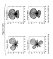
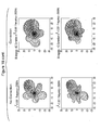
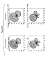
- Figure 19 illustrates beampattern variation vs. signal angle of arrival for the embedded elliptical array at 60° for 500, 1000, 2000 and 3000Hz using the superdirective approach on the left hand side and the method of the present invention on the right hand side.
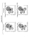
- Figure 20 illustrates beampattern variation vs. signal angle of arrival for the embedded elliptical array at 120° for 500, 1000, 2000 and 3000Hz using the superdirective approach on the left hand side and the method of the present invention on the right hand side.
- Figure 1 shows an obstacle, which may or may not contain local acoustical treatment on the surface thereof and a sensor array of M microphones on the surface.
- a point source of sound is located in the k direction at an angle ⁇ in the x-y plane and an angle ⁇ in the z plane.
- the array is in a plane but the way the beam pattern is "constrained" is very general and can be applied to arrays with 3D geometry.
- the impedance condition i.e. local surface treatment
- the distance between sensors (or microphones) and the shape of the obstacle are all variable.
- d ⁇ , ⁇ , ⁇ ( ⁇ ) be the signal vector at the M sensors for a source at position ( ⁇ , ⁇ , ⁇ ) in spherical co-ordinates.
- n be a noise vector due to the environment, where n is not correlated to the signal d , and where n and d are both dependant upon the frequency ⁇ .
- R nn ( ⁇ ) be the normalised noise correlation matrix, depending on the nature of the noise field.
- R nn ( ⁇ ) can be calculated using a set of non correlated incident plane waves around the sensor array.
- Designing a beamformer consists of finding a weighting vector w opt (complex containing amplitude and phase information), such as the Hermitian product w opt H d , for enhancing the signal of the source in the desired direction (i.e. look direction) while attenuating the noise contribution. According to the superdirective method, this is done by minimising the noise power while looking in the direction of the source, or equivalently, maximising the Signal to Noise ratio under a linear constraint.
- w opt complex containing amplitude and phase information
- H d Hermitian product
- a fixed beamforming algorithm is set forth below, although the inventive method may be extended to adaptive beamforming under constraint (e.g. such as in Frost [9]).
- the noise vectors can be computed analytically for a free-field sensor array, a sensor array embedded in a sphere or an infinite cylinder. Since the determination of n requires computation of the noise acoustic pressure at the M sensors, if a sensor array is embedded in any other shape of obstacle, Infinite Element (IFEM) or Boundary Element (BEM) methods must be used.
- IFEM Infinite Element
- BEM Boundary Element
- the noise field is a set of non-correlated plane waves emanating from all directions and R nn defined in the following way:
- the matrix R nn is generally ill conditioned due to size of the array relative to the acoustic wavelength.
- R nn must be regularised taking into account the fluctuations of each microphone (white noise). Some authors have introduced amplitude and phase variations to account for microphone errors (e.g. Ryan [4]).
- the regularisation is equivalent to a quadratic constraint on the weighting vector w amplitude that can tend to infinity when the matrix is ill conditioned.
- the signal vector d( ⁇ ) contains the signal induced by the acoustic source to be detected, at the M sensors at frequency ⁇ . It depends on the nature of the source (i.e. far field acoustic plane wave, near field, acoustic monopole, or any other type that can be modelled by numerical simulation).
- FIG. 2 is a block diagram of a classical beamformer where weights w 1 *...w M * are applied to the M microphone signals d 1 (n)...d M (n) before being summed into y(n) .
- the superdirective approach minimises the noise energy while looking in the direction of the source.
- Minimising the following functional J(w, ⁇ ) 1 2 w H R nn w + ⁇ (1 - w H d) gives the optimal weight vector w opt ( ⁇ ) .
- the directivity is highly dependent on frequency for simple geometries such as circular arrays or linear arrays in free field or in simple solid geometry such as a sphere.
- Figure 3 is a side view schematic of a symmetrical microphone array embedded in an axi-symmetric truncated cone obstacle having bottom diameter of 10 cm, top diameter 16 cm, and a height of 6 cm.
- the source can be rotated about the array.
- the weight vector is computed for twelve 30° sectors around the array, wherein six of the sectors contain a microphone.
- the beamformer is used in conjunction with a beam steering algorithm. Due to axi-symmetry, only two different weight vectors are required.
- One of the advantages of such an array is that an almost constant beamwidth is achieved when the source to be detected moves around the obstacle. As shown in Figure 3, although the beamwidth is not constant vs. angle of arrival ⁇ , the beam lobes are symmetrical and point towards the look direction. This is no longer the case, however, when the array is elliptic, for example, or when it is embedded in an obstacle whose geometry is not axi-symmetric.
- the beam When the array is no longer circular, the beam varies with the azimuth angle of the source at each frequency.
- the acoustic source to be detected is at a distance of 1 meter and an elevation of 20°. Beampatterns are computed for different source azimuth angles from 0 to 360 degrees.
- the elliptic array is considered herein for illustration purposes only. Other asymmetrical arrays may be used.
- Figure 7 shows the beam patterns for the elliptic array of Figure 6 in free field over a rigid plane, in a delay and sum scheme and for a pure super-directive approach. It will be noted when comparing the beampatterns generated by these two techniques that the beamwidth varies significantly (especially when comparing 0 and 90 degrees).
- the super-directive method provides a narrower beam but suffers from a front-back ambiguity at 0 degrees. There is symmetry at 0 and 90 degrees as the array is symmetrical from those angles.
- the beams at 30 and 60 degrees are very asymmetrical, including the side lobes and the main lobes appear to point in the wrong direction at some frequencies in both cases.
- d ( ⁇ , ⁇ , ⁇ ) be the sensor signal vector for a source at position ( ⁇ , ⁇ , ⁇ ). and d the signal vector of the source to be detected.
- w H opt d 1
- the Hermitian product w H / opt d ⁇ , ⁇ , ⁇ describes the 3D beampattern of the microphone array for a source moving in 3D space at a radius ⁇ from the centre of the array and 0 ⁇ ⁇ ⁇ 2 ⁇ , - ⁇ / 2 ⁇ ⁇ / 2 .
- d ⁇ d be the sensor signal vector at the M microphones for a look direction ⁇ .
- angles ⁇ i and their number depends on the beamwidth or the main lobe beampattern asymmetry after unconstrained minimisation, and the required beamwidth or lobe symmetry.
- Figure 8 shows an example of choice of vectors according to the optimisation process described above, where constraints are added in the functional J to provide the correction.
- the main lobe is symmetrical.
- the strong asymmetric array makes the beam globally "look" in a different direction. This deviation from the look direction depends on the frequency, the geometry of the array and the look direction angle.
- this asymmetry is corrected by choosing a convenient set of vectors d ⁇ j . Additionally, a vector may be chosen to steer to an angle slightly different from the desired look direction.
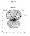
- Figure 9 shows an example of a pair of "asymmetrical" vectors according to the optimisation process described above, where constraints are added in the functional J to provide the asymmetry correction.
- the main lobe is asymmetrical and the desired look direction is 60°.
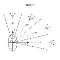
- Figure 10 shows a pair of symmetrical vectors to correct the beamwidth and a single vector to correct the asymmetry.
- the optimisation process for determining w opt consists of minimising a cost function similar to (20).
- This key aspect of the present invention allows, among other things, implementation of a non axi-symmetric microphone array in a non axi-symmetric shape, with reasonably symmetric beam shapes.
- the implementation consists of defining several sectors around the array, and sets of symmetric, asymmetric pairs of vectors or single vectors to correct the beamwidth and the beam lobe asymmetry.
- the inventive beamforming approach is coupled with a beam-steering algorithm that can be based on the optimal weighting coefficients computed for each sector, in a reduced frequency band.
- Figure 12 shows the correction of a beampattern in a super-directive approach for the elliptic array illustrated in Figure 6.
- the beamwidth has been increased using one symmetric pair of vectors d ⁇ +30 ,d ⁇ -30 and the asymmetry has been corrected using d ⁇ +45 .
- the same vectors have been chosen in Figure 13, to correct the poor directivity (delay and sum method), the strong asymmetry, and the undetermined look direction at 60 degrees. It will be noted that the correction shown in Figure 13 is considerable.
- an important application of the present invention is in designing microphone arrays embedded in obstacles having "odd" shapes (non axi-symmetric) and dealing with induced problems such as: beampattern beamwidth variation vs. the look direction angle, loss of look direction, etc.
- the present method allows for the successful implementation of a microphone array in a telephone set for conferencing purposes or increased efficiency for speech recognition.
- Figure 14 shows a mechanical definition of an obstacle that mimics a telephone set, and is used herein to illustrate the application of the inventive method.
- Implementation of fixed beamforming requires the computation of optimal weights for different sectors. To accomplish this the pressure (magnitude and phase) from each source at each microphone must be determined. As no analytical expression is available for such a geometry, numerical methods are used to determine the required data.
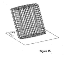
- Figure 15 shows the Boundary Element model mesh (I-DEAS Vibro-acoustics) and the position of the six microphones, where the rigid reflecting plane supporting the obstacle is taken into consideration.
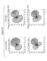
- Figures 18, 19 and 20 show correction of the beampattern and look direction at 30° (Figure 18), 60° (Figure 19) and 120° (Figure 20) using the invention for various frequencies.
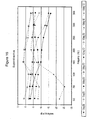
- Figure 17 shows the attenuation ⁇ 30° from the desired look direction (at an elevation of 20°). Comparing Figure 17 to Figure 16 the improvement is obvious. The attenuation now varies by a few dB. There is still a narrowing of the beam at high frequencies but it is reasonably constant over the various look directions.
- Design steps of the present invention can be implemented by a computer program operating on a computer.
- An aspect of the present invention thus provides a storage medium storing processor implementable instructions for controlling a processor to carry out the method as hereinabove described.
- the computer program can be obtained in electronic form for example by downloading the code over a network such as the internet.
- an electrical signal carrying processor implementable instructions for controlling a processor to carry out the method as hereinbefore described.
- a further aspect of the present invention also comprises the step of materially producing the subject of the above disclosed design method.
Landscapes
- Health & Medical Sciences (AREA)
- Otolaryngology (AREA)
- Physics & Mathematics (AREA)
- Engineering & Computer Science (AREA)
- Acoustics & Sound (AREA)
- Signal Processing (AREA)
- Circuit For Audible Band Transducer (AREA)
- Measurement Of Velocity Or Position Using Acoustic Or Ultrasonic Waves (AREA)
- Obtaining Desirable Characteristics In Audible-Bandwidth Transducers (AREA)
Applications Claiming Priority (2)
| Application Number | Priority Date | Filing Date | Title |
|---|---|---|---|
| GB0229059 | 2002-12-12 | ||
| GBGB0229059.1A GB0229059D0 (en) | 2002-12-12 | 2002-12-12 | Method of broadband constant directivity beamforming for non linear and non axi-symmetric sensor arrays embedded in an obstacle |
Publications (3)
| Publication Number | Publication Date |
|---|---|
| EP1429581A2 true EP1429581A2 (de) | 2004-06-16 |
| EP1429581A3 EP1429581A3 (de) | 2009-04-01 |
| EP1429581B1 EP1429581B1 (de) | 2011-01-26 |
Family
ID=9949605
Family Applications (1)
| Application Number | Title | Priority Date | Filing Date |
|---|---|---|---|
| EP03257798A Expired - Lifetime EP1429581B1 (de) | 2002-12-12 | 2003-12-11 | Verfahren zur breitbandingen richtungskonstanten Strahlungsdiagrammformung für nicht linear und nicht axialsymmetrisch angeordnete Arrays von Sensoren, die in einem Hindernis eingebettet sind |
Country Status (5)
| Country | Link |
|---|---|
| US (1) | US7269263B2 (de) |
| EP (1) | EP1429581B1 (de) |
| CA (1) | CA2453048C (de) |
| DE (1) | DE60335853D1 (de) |
| GB (1) | GB0229059D0 (de) |
Cited By (2)
| Publication number | Priority date | Publication date | Assignee | Title |
|---|---|---|---|---|
| EP1432280A3 (de) * | 2002-12-16 | 2009-04-01 | Mitel Networks Corporation | Verfahren zur Erweiterung des Frequenzbereichs eines Strahlungsdiagrammformers ohne räumliches Aliasing |
| US7840013B2 (en) | 2003-07-01 | 2010-11-23 | Mitel Networks Corporation | Microphone array with physical beamforming using omnidirectional microphones |
Families Citing this family (61)
| Publication number | Priority date | Publication date | Assignee | Title |
|---|---|---|---|---|
| US7031442B1 (en) | 1997-02-10 | 2006-04-18 | Genesys Telecommunications Laboratories, Inc. | Methods and apparatus for personal routing in computer-simulated telephony |
| US6480600B1 (en) | 1997-02-10 | 2002-11-12 | Genesys Telecommunications Laboratories, Inc. | Call and data correspondence in a call-in center employing virtual restructuring for computer telephony integrated functionality |
| US6104802A (en) | 1997-02-10 | 2000-08-15 | Genesys Telecommunications Laboratories, Inc. | In-band signaling for routing |
| US20010040887A1 (en) * | 1997-10-09 | 2001-11-15 | Yuri Shtivelman | Apparatus and methods enhancing call routing to and within call-centers |
| US6985943B2 (en) | 1998-09-11 | 2006-01-10 | Genesys Telecommunications Laboratories, Inc. | Method and apparatus for extended management of state and interaction of a remote knowledge worker from a contact center |
| US6711611B2 (en) | 1998-09-11 | 2004-03-23 | Genesis Telecommunications Laboratories, Inc. | Method and apparatus for data-linking a mobile knowledge worker to home communication-center infrastructure |
| USRE46528E1 (en) | 1997-11-14 | 2017-08-29 | Genesys Telecommunications Laboratories, Inc. | Implementation of call-center outbound dialing capability at a telephony network level |
| US7907598B2 (en) | 1998-02-17 | 2011-03-15 | Genesys Telecommunication Laboratories, Inc. | Method for implementing and executing communication center routing strategies represented in extensible markup language |
| US6332154B2 (en) | 1998-09-11 | 2001-12-18 | Genesys Telecommunications Laboratories, Inc. | Method and apparatus for providing media-independent self-help modules within a multimedia communication-center customer interface |
| USRE46153E1 (en) | 1998-09-11 | 2016-09-20 | Genesys Telecommunications Laboratories, Inc. | Method and apparatus enabling voice-based management of state and interaction of a remote knowledge worker in a contact center environment |
| US7929978B2 (en) | 1999-12-01 | 2011-04-19 | Genesys Telecommunications Laboratories, Inc. | Method and apparatus for providing enhanced communication capability for mobile devices on a virtual private network |
| EP1524879B1 (de) * | 2003-06-30 | 2014-05-07 | Nuance Communications, Inc. | Freisprechanlage zur Verwendung in einem Fahrzeug |
| GB0405790D0 (en) * | 2004-03-15 | 2004-04-21 | Mitel Networks Corp | Universal microphone array stand |
| US7783060B2 (en) * | 2005-05-10 | 2010-08-24 | The United States Of America As Represented By The Administrator Of The National Aeronautics And Space Administration | Deconvolution methods and systems for the mapping of acoustic sources from phased microphone arrays |
| US8170234B2 (en) * | 2005-05-10 | 2012-05-01 | The United States of America by the Administrator of the National Aeronautics and Space Adminstration | Deconvolution methods and systems for the mapping of acoustic sources from phased microphone arrays |
| US20070047743A1 (en) * | 2005-08-26 | 2007-03-01 | Step Communications Corporation, A Nevada Corporation | Method and apparatus for improving noise discrimination using enhanced phase difference value |
| US20070050441A1 (en) * | 2005-08-26 | 2007-03-01 | Step Communications Corporation,A Nevada Corporati | Method and apparatus for improving noise discrimination using attenuation factor |
| US7472041B2 (en) * | 2005-08-26 | 2008-12-30 | Step Communications Corporation | Method and apparatus for accommodating device and/or signal mismatch in a sensor array |
| US7436188B2 (en) * | 2005-08-26 | 2008-10-14 | Step Communications Corporation | System and method for improving time domain processed sensor signals |
| US20070047742A1 (en) * | 2005-08-26 | 2007-03-01 | Step Communications Corporation, A Nevada Corporation | Method and system for enhancing regional sensitivity noise discrimination |
| US7415372B2 (en) * | 2005-08-26 | 2008-08-19 | Step Communications Corporation | Method and apparatus for improving noise discrimination in multiple sensor pairs |
| US7619563B2 (en) | 2005-08-26 | 2009-11-17 | Step Communications Corporation | Beam former using phase difference enhancement |
| US9008075B2 (en) | 2005-12-22 | 2015-04-14 | Genesys Telecommunications Laboratories, Inc. | System and methods for improving interaction routing performance |
| GB0619825D0 (en) * | 2006-10-06 | 2006-11-15 | Craven Peter G | Microphone array |
| FR2924884B1 (fr) * | 2007-12-11 | 2009-12-04 | Eads Secure Networks | Reduction d'interferences dans un signal a repartition de frequences orthogonales |
| GB0906269D0 (en) * | 2009-04-09 | 2009-05-20 | Ntnu Technology Transfer As | Optimal modal beamformer for sensor arrays |
| US9964625B2 (en) * | 2011-06-27 | 2018-05-08 | General Electric Company | Electrical substation fault monitoring and diagnostics |
| KR101645590B1 (ko) * | 2014-08-22 | 2016-08-05 | 한국지이초음파 유한회사 | 적응적인 수신 빔 집속 방법 및 그 장치 |
| US9565493B2 (en) | 2015-04-30 | 2017-02-07 | Shure Acquisition Holdings, Inc. | Array microphone system and method of assembling the same |
| US9554207B2 (en) | 2015-04-30 | 2017-01-24 | Shure Acquisition Holdings, Inc. | Offset cartridge microphones |
| US10367948B2 (en) | 2017-01-13 | 2019-07-30 | Shure Acquisition Holdings, Inc. | Post-mixing acoustic echo cancellation systems and methods |
| US10349169B2 (en) | 2017-10-31 | 2019-07-09 | Bose Corporation | Asymmetric microphone array for speaker system |
| US11209306B2 (en) * | 2017-11-02 | 2021-12-28 | Fluke Corporation | Portable acoustic imaging tool with scanning and analysis capability |
| US20190129027A1 (en) | 2017-11-02 | 2019-05-02 | Fluke Corporation | Multi-modal acoustic imaging tool |
| US11494158B2 (en) * | 2018-05-31 | 2022-11-08 | Shure Acquisition Holdings, Inc. | Augmented reality microphone pick-up pattern visualization |
| CN112335261B (zh) | 2018-06-01 | 2023-07-18 | 舒尔获得控股公司 | 图案形成麦克风阵列 |
| US11297423B2 (en) | 2018-06-15 | 2022-04-05 | Shure Acquisition Holdings, Inc. | Endfire linear array microphone |
| JP2021532355A (ja) | 2018-07-24 | 2021-11-25 | フルークコーポレイションFluke Corporation | 音響画像にタグを付けて関連付けるためのシステム及び方法 |
| US11310596B2 (en) | 2018-09-20 | 2022-04-19 | Shure Acquisition Holdings, Inc. | Adjustable lobe shape for array microphones |
| US11558693B2 (en) | 2019-03-21 | 2023-01-17 | Shure Acquisition Holdings, Inc. | Auto focus, auto focus within regions, and auto placement of beamformed microphone lobes with inhibition and voice activity detection functionality |
| JP7572964B2 (ja) | 2019-03-21 | 2024-10-24 | シュアー アクイジッション ホールディングス インコーポレイテッド | 阻止機能を伴うビーム形成マイクロフォンローブの自動集束、領域内自動集束、および自動配置 |
| US11303981B2 (en) | 2019-03-21 | 2022-04-12 | Shure Acquisition Holdings, Inc. | Housings and associated design features for ceiling array microphones |
| TW202101422A (zh) | 2019-05-23 | 2021-01-01 | 美商舒爾獲得控股公司 | 可操縱揚聲器陣列、系統及其方法 |
| WO2020243471A1 (en) | 2019-05-31 | 2020-12-03 | Shure Acquisition Holdings, Inc. | Low latency automixer integrated with voice and noise activity detection |
| CN111385685A (zh) * | 2019-06-28 | 2020-07-07 | 深圳国威电子有限公司 | 一种具有拾音器排列矩阵呈非线性的无线通讯装置 |
| CN114467312A (zh) | 2019-08-23 | 2022-05-10 | 舒尔获得控股公司 | 具有改进方向性的二维麦克风阵列 |
| CN114207465A (zh) * | 2019-09-17 | 2022-03-18 | 卡拉汉创新有限公司 | 声纳系统和方法 |
| US12028678B2 (en) | 2019-11-01 | 2024-07-02 | Shure Acquisition Holdings, Inc. | Proximity microphone |
| US11552611B2 (en) | 2020-02-07 | 2023-01-10 | Shure Acquisition Holdings, Inc. | System and method for automatic adjustment of reference gain |
| USD944776S1 (en) | 2020-05-05 | 2022-03-01 | Shure Acquisition Holdings, Inc. | Audio device |
| US11706562B2 (en) | 2020-05-29 | 2023-07-18 | Shure Acquisition Holdings, Inc. | Transducer steering and configuration systems and methods using a local positioning system |
| CN112581974B (zh) * | 2020-11-30 | 2023-10-24 | 科大讯飞股份有限公司 | 波束设计方法、装置、设备及存储介质 |
| JP7814400B2 (ja) | 2021-01-28 | 2026-02-16 | シュアー アクイジッション ホールディングス インコーポレイテッド | ハイブリッドオーディオビーム形成システム |
| US12452584B2 (en) | 2021-01-29 | 2025-10-21 | Shure Acquisition Holdings, Inc. | Scalable conferencing systems and methods |
| US12542123B2 (en) | 2021-08-31 | 2026-02-03 | Shure Acquisition Holdings, Inc. | Mask non-linear processor for acoustic echo cancellation |
| US12289584B2 (en) | 2021-10-04 | 2025-04-29 | Shure Acquisition Holdings, Inc. | Networked automixer systems and methods |
| US12262173B2 (en) * | 2021-10-25 | 2025-03-25 | Intel Corporation | Audio processing device and method for acoustic angle of arrival detection using audio signals of a virtual rotating microphone |
| EP4427465A1 (de) | 2021-11-05 | 2024-09-11 | Shure Acquisition Holdings, Inc. | Verteilter algorithmus zur automatischen mischung von sprache über drahtlose netzwerke |
| US12250526B2 (en) | 2022-01-07 | 2025-03-11 | Shure Acquisition Holdings, Inc. | Audio beamforming with nulling control system and methods |
| CN114584895B (zh) * | 2022-05-07 | 2022-08-05 | 之江实验室 | 一种用于波束成形的声学收发阵列排布方法和装置 |
| US12598261B2 (en) | 2022-09-28 | 2026-04-07 | Shure Acquisition Holdings, Inc. | Wideband doubletalk detection for optimization of acoustic echo cancellation |
Family Cites Families (7)
| Publication number | Priority date | Publication date | Assignee | Title |
|---|---|---|---|---|
| US5592441A (en) * | 1995-10-06 | 1997-01-07 | Martin Marietta Corporation | High-gain directional transducer array |
| US6041127A (en) * | 1997-04-03 | 2000-03-21 | Lucent Technologies Inc. | Steerable and variable first-order differential microphone array |
| CA2292357A1 (en) * | 1998-12-18 | 2000-06-18 | Michael R. Stinson | Microphone array diffracting structure |
| US7068801B1 (en) * | 1998-12-18 | 2006-06-27 | National Research Council Of Canada | Microphone array diffracting structure |
| US7039198B2 (en) * | 2000-11-10 | 2006-05-02 | Quindi | Acoustic source localization system and method |
| US7142677B2 (en) * | 2001-07-17 | 2006-11-28 | Clarity Technologies, Inc. | Directional sound acquisition |
| US20030147539A1 (en) * | 2002-01-11 | 2003-08-07 | Mh Acoustics, Llc, A Delaware Corporation | Audio system based on at least second-order eigenbeams |
-
2002
- 2002-12-12 GB GBGB0229059.1A patent/GB0229059D0/en not_active Ceased
-
2003
- 2003-12-11 DE DE60335853T patent/DE60335853D1/de not_active Expired - Lifetime
- 2003-12-11 US US10/732,283 patent/US7269263B2/en not_active Expired - Lifetime
- 2003-12-11 EP EP03257798A patent/EP1429581B1/de not_active Expired - Lifetime
- 2003-12-11 CA CA002453048A patent/CA2453048C/en not_active Expired - Lifetime
Cited By (2)
| Publication number | Priority date | Publication date | Assignee | Title |
|---|---|---|---|---|
| EP1432280A3 (de) * | 2002-12-16 | 2009-04-01 | Mitel Networks Corporation | Verfahren zur Erweiterung des Frequenzbereichs eines Strahlungsdiagrammformers ohne räumliches Aliasing |
| US7840013B2 (en) | 2003-07-01 | 2010-11-23 | Mitel Networks Corporation | Microphone array with physical beamforming using omnidirectional microphones |
Also Published As
| Publication number | Publication date |
|---|---|
| EP1429581B1 (de) | 2011-01-26 |
| US20040120532A1 (en) | 2004-06-24 |
| GB0229059D0 (en) | 2003-01-15 |
| CA2453048C (en) | 2008-01-29 |
| US7269263B2 (en) | 2007-09-11 |
| CA2453048A1 (en) | 2004-06-12 |
| EP1429581A3 (de) | 2009-04-01 |
| DE60335853D1 (de) | 2011-03-10 |
Similar Documents
| Publication | Publication Date | Title |
|---|---|---|
| EP1429581B1 (de) | Verfahren zur breitbandingen richtungskonstanten Strahlungsdiagrammformung für nicht linear und nicht axialsymmetrisch angeordnete Arrays von Sensoren, die in einem Hindernis eingebettet sind | |
| US7366310B2 (en) | Microphone array diffracting structure | |
| US9445198B2 (en) | Polyhedral audio system based on at least second-order eigenbeams | |
| Koretz et al. | Dolph–Chebyshev beampattern design for spherical arrays | |
| US8433075B2 (en) | Audio system based on at least second-order eigenbeams | |
| Huang et al. | Robust and steerable Kronecker product differential beamforming with rectangular microphone arrays | |
| Ryan et al. | Array optimization applied in the near field of a microphone array | |
| Borra et al. | Uniform linear arrays of first-order steerable differential microphones | |
| Xu et al. | A modified differential beamforming and its application for DOA estimation of low frequency underwater signal | |
| US20080247565A1 (en) | Position-Independent Microphone System | |
| Huang et al. | Kronecker Product Beamforming with Multiple Differential Microphone Arrays. | |
| Albertini et al. | Two-stage beamforming with arbitrary planar arrays of differential microphone array units | |
| Huang et al. | On the design of robust steerable frequency-invariant beampatterns with concentric circular microphone arrays | |
| Kajala et al. | Filter-and-sum beamformer with adjustable filter characteristics | |
| Frank et al. | Constant-beamwidth linearly constrained minimum variance beamformer | |
| Kleiman et al. | Constant-beamwidth beamforming with nonuniform concentric ring arrays | |
| Yu et al. | A robust wavenumber-domain superdirective beamforming for endfire arrays | |
| EP1986464A1 (de) | Hochdirektives, längsstrahlendes Lautsprecherarray | |
| Jin et al. | Design of optimal linear differential microphone arrays based array geometry optimization | |
| Chen et al. | Planar array geometry optimization for region sound acquisition | |
| Zhao et al. | Design of robust differential beamformers with microphone arrays of arbitrary planar geometry | |
| CN110457796B (zh) | 无规平面差分传声器阵列阵元位置的优化方法 | |
| CN120874589A (zh) | 一种适用于任意阵的宽带高增益波束图优化方法 | |
| Itzhak et al. | Kronecker-product beamforming with sparse concentric circular arrays | |
| CN119207452A (zh) | 一种具有波束偏转恒定能力的波束形成方法、系统、存储介质和电子设备 |
Legal Events
| Date | Code | Title | Description |
|---|---|---|---|
| PUAI | Public reference made under article 153(3) epc to a published international application that has entered the european phase |
Free format text: ORIGINAL CODE: 0009012 |
|
| AK | Designated contracting states |
Kind code of ref document: A2 Designated state(s): AT BE BG CH CY CZ DE DK EE ES FI FR GB GR HU IE IT LI LU MC NL PT RO SE SI SK TR |
|
| AX | Request for extension of the european patent |
Extension state: AL LT LV MK |
|
| RAP1 | Party data changed (applicant data changed or rights of an application transferred) |
Owner name: CELTIC TECH JET LIMITED |
|
| RAP1 | Party data changed (applicant data changed or rights of an application transferred) |
Owner name: MITEL NETWORKS CORPORATION |
|
| PUAL | Search report despatched |
Free format text: ORIGINAL CODE: 0009013 |
|
| AK | Designated contracting states |
Kind code of ref document: A3 Designated state(s): AT BE BG CH CY CZ DE DK EE ES FI FR GB GR HU IE IT LI LU MC NL PT RO SE SI SK TR |
|
| AX | Request for extension of the european patent |
Extension state: AL LT LV MK |
|
| 17P | Request for examination filed |
Effective date: 20090825 |
|
| AKX | Designation fees paid |
Designated state(s): DE FR GB |
|
| GRAP | Despatch of communication of intention to grant a patent |
Free format text: ORIGINAL CODE: EPIDOSNIGR1 |
|
| GRAS | Grant fee paid |
Free format text: ORIGINAL CODE: EPIDOSNIGR3 |
|
| GRAA | (expected) grant |
Free format text: ORIGINAL CODE: 0009210 |
|
| AK | Designated contracting states |
Kind code of ref document: B1 Designated state(s): DE FR GB |
|
| REG | Reference to a national code |
Ref country code: GB Ref legal event code: FG4D |
|
| REF | Corresponds to: |
Ref document number: 60335853 Country of ref document: DE Date of ref document: 20110310 Kind code of ref document: P |
|
| REG | Reference to a national code |
Ref country code: DE Ref legal event code: R096 Ref document number: 60335853 Country of ref document: DE Effective date: 20110310 |
|
| PLBE | No opposition filed within time limit |
Free format text: ORIGINAL CODE: 0009261 |
|
| STAA | Information on the status of an ep patent application or granted ep patent |
Free format text: STATUS: NO OPPOSITION FILED WITHIN TIME LIMIT |
|
| 26N | No opposition filed |
Effective date: 20111027 |
|
| REG | Reference to a national code |
Ref country code: DE Ref legal event code: R097 Ref document number: 60335853 Country of ref document: DE Effective date: 20111027 |
|
| REG | Reference to a national code |
Ref country code: FR Ref legal event code: PLFP Year of fee payment: 13 |
|
| REG | Reference to a national code |
Ref country code: FR Ref legal event code: PLFP Year of fee payment: 14 |
|
| REG | Reference to a national code |
Ref country code: FR Ref legal event code: PLFP Year of fee payment: 15 |
|
| PGFP | Annual fee paid to national office [announced via postgrant information from national office to epo] |
Ref country code: FR Payment date: 20221010 Year of fee payment: 20 |
|
| PGFP | Annual fee paid to national office [announced via postgrant information from national office to epo] |
Ref country code: GB Payment date: 20221020 Year of fee payment: 20 Ref country code: DE Payment date: 20221018 Year of fee payment: 20 |
|
| REG | Reference to a national code |
Ref country code: DE Ref legal event code: R071 Ref document number: 60335853 Country of ref document: DE |
|
| REG | Reference to a national code |
Ref country code: GB Ref legal event code: PE20 Expiry date: 20231210 |
|
| PG25 | Lapsed in a contracting state [announced via postgrant information from national office to epo] |
Ref country code: GB Free format text: LAPSE BECAUSE OF EXPIRATION OF PROTECTION Effective date: 20231210 |
|
| PG25 | Lapsed in a contracting state [announced via postgrant information from national office to epo] |
Ref country code: GB Free format text: LAPSE BECAUSE OF EXPIRATION OF PROTECTION Effective date: 20231210 |