EP1429553A1 - Electronic camera - Google Patents
Electronic camera Download PDFInfo
- Publication number
- EP1429553A1 EP1429553A1 EP02746011A EP02746011A EP1429553A1 EP 1429553 A1 EP1429553 A1 EP 1429553A1 EP 02746011 A EP02746011 A EP 02746011A EP 02746011 A EP02746011 A EP 02746011A EP 1429553 A1 EP1429553 A1 EP 1429553A1
- Authority
- EP
- European Patent Office
- Prior art keywords
- image
- derivative
- original image
- unit
- mpu
- Prior art date
- Legal status (The legal status is an assumption and is not a legal conclusion. Google has not performed a legal analysis and makes no representation as to the accuracy of the status listed.)
- Granted
Links
- 238000012546 transfer Methods 0.000 claims abstract description 153
- 238000003384 imaging method Methods 0.000 claims abstract description 14
- 230000003068 static effect Effects 0.000 claims description 10
- 230000004044 response Effects 0.000 claims description 8
- 238000012544 monitoring process Methods 0.000 claims description 6
- 239000004973 liquid crystal related substance Substances 0.000 description 31
- 230000006870 function Effects 0.000 description 27
- 238000000034 method Methods 0.000 description 23
- 230000008569 process Effects 0.000 description 23
- 238000012545 processing Methods 0.000 description 12
- 230000009467 reduction Effects 0.000 description 11
- 230000008859 change Effects 0.000 description 8
- 238000012790 confirmation Methods 0.000 description 7
- 230000000694 effects Effects 0.000 description 6
- 238000005516 engineering process Methods 0.000 description 6
- 230000001413 cellular effect Effects 0.000 description 4
- 230000006835 compression Effects 0.000 description 2
- 238000007906 compression Methods 0.000 description 2
- 238000010586 diagram Methods 0.000 description 2
- 238000012552 review Methods 0.000 description 2
- 238000009825 accumulation Methods 0.000 description 1
- 238000006243 chemical reaction Methods 0.000 description 1
- 239000003086 colorant Substances 0.000 description 1
- 230000003247 decreasing effect Effects 0.000 description 1
- 230000002708 enhancing effect Effects 0.000 description 1
- 239000000284 extract Substances 0.000 description 1
- 238000012986 modification Methods 0.000 description 1
- 230000004048 modification Effects 0.000 description 1
- 238000003825 pressing Methods 0.000 description 1
- 230000002265 prevention Effects 0.000 description 1
- 239000000725 suspension Substances 0.000 description 1
Images





Classifications
-
- H—ELECTRICITY
- H04—ELECTRIC COMMUNICATION TECHNIQUE
- H04N—PICTORIAL COMMUNICATION, e.g. TELEVISION
- H04N5/00—Details of television systems
- H04N5/76—Television signal recording
- H04N5/765—Interface circuits between an apparatus for recording and another apparatus
- H04N5/77—Interface circuits between an apparatus for recording and another apparatus between a recording apparatus and a television camera
- H04N5/772—Interface circuits between an apparatus for recording and another apparatus between a recording apparatus and a television camera the recording apparatus and the television camera being placed in the same enclosure
-
- H—ELECTRICITY
- H04—ELECTRIC COMMUNICATION TECHNIQUE
- H04N—PICTORIAL COMMUNICATION, e.g. TELEVISION
- H04N5/00—Details of television systems
- H04N5/76—Television signal recording
- H04N5/765—Interface circuits between an apparatus for recording and another apparatus
-
- H—ELECTRICITY
- H04—ELECTRIC COMMUNICATION TECHNIQUE
- H04N—PICTORIAL COMMUNICATION, e.g. TELEVISION
- H04N5/00—Details of television systems
- H04N5/76—Television signal recording
- H04N5/907—Television signal recording using static stores, e.g. storage tubes or semiconductor memories
-
- H—ELECTRICITY
- H04—ELECTRIC COMMUNICATION TECHNIQUE
- H04N—PICTORIAL COMMUNICATION, e.g. TELEVISION
- H04N5/00—Details of television systems
- H04N5/76—Television signal recording
- H04N5/91—Television signal processing therefor
- H04N5/92—Transformation of the television signal for recording, e.g. modulation, frequency changing; Inverse transformation for playback
- H04N5/9201—Transformation of the television signal for recording, e.g. modulation, frequency changing; Inverse transformation for playback involving the multiplexing of an additional signal and the video signal
- H04N5/9205—Transformation of the television signal for recording, e.g. modulation, frequency changing; Inverse transformation for playback involving the multiplexing of an additional signal and the video signal the additional signal being at least another television signal
-
- H—ELECTRICITY
- H04—ELECTRIC COMMUNICATION TECHNIQUE
- H04N—PICTORIAL COMMUNICATION, e.g. TELEVISION
- H04N9/00—Details of colour television systems
- H04N9/79—Processing of colour television signals in connection with recording
- H04N9/80—Transformation of the television signal for recording, e.g. modulation, frequency changing; Inverse transformation for playback
- H04N9/804—Transformation of the television signal for recording, e.g. modulation, frequency changing; Inverse transformation for playback involving pulse code modulation of the colour picture signal components
- H04N9/8042—Transformation of the television signal for recording, e.g. modulation, frequency changing; Inverse transformation for playback involving pulse code modulation of the colour picture signal components involving data reduction
-
- H—ELECTRICITY
- H04—ELECTRIC COMMUNICATION TECHNIQUE
- H04N—PICTORIAL COMMUNICATION, e.g. TELEVISION
- H04N9/00—Details of colour television systems
- H04N9/79—Processing of colour television signals in connection with recording
- H04N9/80—Transformation of the television signal for recording, e.g. modulation, frequency changing; Inverse transformation for playback
- H04N9/82—Transformation of the television signal for recording, e.g. modulation, frequency changing; Inverse transformation for playback the individual colour picture signal components being recorded simultaneously only
- H04N9/8205—Transformation of the television signal for recording, e.g. modulation, frequency changing; Inverse transformation for playback the individual colour picture signal components being recorded simultaneously only involving the multiplexing of an additional signal and the colour video signal
- H04N9/8227—Transformation of the television signal for recording, e.g. modulation, frequency changing; Inverse transformation for playback the individual colour picture signal components being recorded simultaneously only involving the multiplexing of an additional signal and the colour video signal the additional signal being at least another television signal
Definitions
- the present invention relates to an electronic camera which generates derivative images for external transfer from captured original images.
- the present invention particularly relates to an image managing technology, an image displaying technology, and a user interface technology for these derivative images.
- Images generated in an electronic camera are outputted to a personal computer, a printer, a mass memory unit, a cellular phone, a digital photograph server on the Internet, and so on when necessary.
- a cellular phone or the like handles images with an extremely lower pixel density compared with that of images handled by a personal computer, a printer, and the like. Therefore, in a case where an image with substantially the same pixel density as images used with a personal computer or a printer is transferred to a cellular phone, the cellular phone cannot receive the image because the image data exceeds its data capacity, resulting in data loss.
- the inventor of the present application has come up with an idea that a derivative image with a reduced data size is generated when necessary in an electronic camera to use the derivative image for external transfer.
- the derivative image and its original image from which the derivative image is generated both exist in a recording unit of the electronic camera.
- a first embodiment is an embodiment of an electronic camera corresponding to the inventions of claims 1, 4, 5, 7 to 9, 12, and 13.
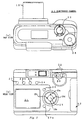
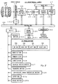
- Fig. 1(a) and Fig. 1(b) are views each showing an external appearance of this electronic camera 11. Note that Fig. 1(a) is a top view of the electronic camera 11, and Fig. 1(b) is a rear view of the electronic camera 11. Fig. 2 is a block diagram explaining the internal configuration of the electronic camera 11.
- a lens 12 is attached to the electronic camera 11.
- An image sensor 13 is disposed in an image space of this lens 12.
- This image sensor 13 is controlled by a timing generator 13a and captures a subject.
- the image captured by this image sensor 13 (namely, an original image) is digitized by an image processing unit 14 and an A/D converting unit 15, and thereafter, given to a digital signal processor (hereinafter, referred to as a DSP) 16.
- This DSP 16 is connected to a buffer memory 18 and a memory card 19 via a data bus 17.
- the DSP 16 performs two-dimensional image processing, image compression processing, and so on for the original image while exchanging image data with this buffer memory 18.
- the original image processed in the DSP 16 is recorded on the memory card 19 in an EXIF file format.
- timing generator 13a image processing unit 14, DSP 16, buffer memory 18, and memory card 19 are connected to a microprocessor (hereinafter, referred to as an MPU) 21 via a system bus 20 for control and data transfer.
- MPU microprocessor
- a release button 22 connected to this MPU 21, connected are a release button 22, a cross button 23, a menu button 24, a command dial 25, a zoom button 26, a display switch button 27, a transfer button 28, a derivative image generating button 29, an enter key 29a, and an erase button 29b.
- the aforesaid cross button 23 is constituted of four-direction keys consisting of an up key 23a, a down key 23b, a left key 23c, and a right key 23d.
- a frame memory 30 is connected to the aforesaid system bus 20. Image data in this frame memory 30 is displayed on a liquid crystal display unit 31 provided on a rear face of the electronic camera 11.
- an interface 32 transferring an image having a flag, to an external transfer destination in response to the operation to the transfer button 28.
- An imaging unit described in the claims corresponds to the image sensor 13, the timing generator 13a, the image processing unit 14, the A/D converting unit 15, and the DSP 16.
- a derivative image generating unit described in the claims corresponds to 'a derivative image generating function' of the MPU 21 (or the DSP 16).
- a recording unit described in the claims corresponds to 'a function of file management of the memory card 19' of the MPU 21.
- a transfer unit described in the claims corresponds to the interface 32.
- An erase control unit described in the claims corresponds to 'a function of receiving an erase command for the original image from a user's operation or the like of the cross button 23' of the MPU 21.
- a transfer control unit described in the claims corresponds to 'a function of receiving a file transfer command for an original image from a user's operation or the like of the cross button 23' of the MPU 21.
- a protect control unit described in the claims corresponds to 'a function of receiving a protect command for an original image from a user's operation or the like of the cross button 23' of the MPU 21.
- An original image erase control unit described in the claims corresponds to 'a function of receiving an erase command for only an original image from a user's operation or the like of the cross button 23' of the MPU 21.
- a thumbnail generating unit described in the claims corresponds to 'a function of generating a thumbnail image to append it to a file header of an original image' of the MPU 21 (or the DSP 16).
- a control unit described in the claims corresponds to 'a function of erasing from the memory card 19 a derivative image which has been transferred' of the MPU 21.
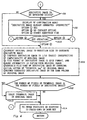
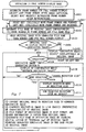
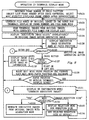
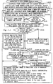
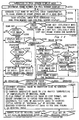
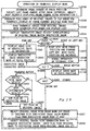
- Fig. 3 and Fig.4 are flowcharts explaining a derivative image generating process. Note that this process starts as a part of processes in response to pressing of the down key 23b. Hereinafter, the derivative image generating process will be explained following the steps in Fig. 3 and Fig. 4. Step S1: When a user presses down the down key 23b, the MPU 21 first determines a current operation mode of the electronic camera 11.
- the MPU 21 shifts its operation to Step S2.
- Step S2 The MPU 21 determines a current display status of the liquid crystal display unit 31.
- Step 3 The MPU 21 obtains information on an available storage space of the memory card 19.
- the MPU 21 gives up generating a new derivative image and shifts its operation to Step S14.
- Step S4 The MPU 21 overlappinly displays the following confirmation menu on a display image on the liquid crystal display unit 31. Header "Generate a derivative image?" Option 1 ⁇ Yes (default option) Option 2 ⁇ No Option 3 ⁇ Change reduction size
- Step S5 The MPU 21 monitors a user's operation to the cross button 23 to receive a selected one of the above options 1 ⁇ to 3 ⁇ .
- Step S8 a user hits the right key 23d once, determining selection of the option 1 ⁇ .
- the MPU 21 shifts its operation to Step S8.
- the user hits the right key 23d once after hitting the down key 23b once, determining selection of the option 2 ⁇ .
- the MPU 21 stops generating a new derivative image to shifts its operation to Step S14.
- Step S6 The MPU 21 additionally displays the following confirmation menu on the display image on the liquid crystal display unit 31. Header "Change reduction size" Option 1 ⁇ 640 x 480 (default at the shipping time) Option 2 ⁇ 320 x 240 Option 3 ⁇ 160 x 120 Option 4 ⁇ 96 x 72
- Step S7 The MPU 21 monitors the user's operation to the cross button 23 to receive the selection and determination of the image size (reduction size) of the derivative image. The MPU 21 uses the image size determined here as a default thereafter. After this operation, the MPU 21 shifts its operation back to Step S4.
- Step S8 The MPU 21 searches files in the memory card 19 to determine whether or not a derivative image to be generated already exists.
- Step S9 The MPU 21 overlappingly displays the following confirmation menu on the display image on the liquid crystal display unit 31. Header "A derivative image already generated. Overwrite?" Option 1 ⁇ Yes Option 2 ⁇ No (default option) Option 3 ⁇ Change reduction size
- Step S10 The MPU 21 monitors the user's operation to the cross button 23 to receive a selected one of the above options 1 ⁇ to 3 ⁇ .
- the MPU 21 stops generating a new derivative image to shift its operation to Step S14.
- the user hits the right key 23d once after hitting the down key 23b once, determining selection of the option 3 ⁇ .
- the MPU 21 shifts its operation to Step S6.
- Step 11 In the case of the reproduction mode, the MPU 21 reads out from the memory card 19 a compressed file of the original image currently displayed on the liquid crystal display unit 31 to store this compressed file in the buffer memory 18. The DSP 16 expands this compressed file to develop the original image in the buffer memory 18.
- the MPU 21 (or the DSP 16) performs resolution-conversion on this original image in the buffer memory 18 to have an image of a default image size to generate a derivative image.
- the DSP 16 compresses this derivative image to, for example, about 1/16 irrespective of the compressibility of the original image.
- the MPU 21 copies header information of the original image, appends it to the compressed data of the derivative image to generate a compressed file in the EXIF file format.
- the MPU 21 replaces an initial letter of a file name "DSCN***.jpg" of the original image with a letter (for example, "S” or the like) according to the image size to create a file name of the derivative image.
- the associations between the original image and the derivative image are made according to the file name rule.
- the MPU 21 records thus generated file of the derivative image in the same folder as the original image in the memory card 19.
- Step S12 The MPU 21 compares the number of pixels of a thumbnail image appended in the file of the original image with the number of pixels of the derivative image newly generated.
- the MPU 21 shifts its operation to Step S13.
- Step S14 The MPU 21 erases the thumbnail image from the file of the original image to reduce a file space of the original image. Thereafter, when the thumbnail image of the original image is required, the derivative image is used as a substitute for the thumbnail image.
- Step S14 The MPU 21 calls other process routines which are to be executed when the down key 23b is pressed down.
- Fig. 5 is a flowchart showing a process routine of file manipulation.
- the file manipulation to images will be explained following the steps shown in Fig. 5.
- Step S18 The user first switches the mode of the electronic camera 11 to the reproduction mode, and selects on the liquid crystal display unit 31 an original image as an object of the file manipulation.
- Step S19 When the original image as the object of the manipulation is selected, the MPU 21 changes the initial letter of the file name of this original image to create the file name of a derivative image.
- the MPU 21 searches the memory card 19 for the file name of the derivative image and determines whether or not the concerning derivative image exists.
- Step S20 Next, the MPU 21 monitors the user's operation to the menu button 24 and the transfer button 28.
- Step S21 When the original image as the object of the manipulation has a derivative image, the MPU 21 transfers this derivative image to a preset external transfer destination via the interface 32. Upon completion of the transfer operation, the MPU 21 erases from the memory card 19 the derivative image which has been transferred, to thereby increase an available storage space of the memory card 19.
- the original image as the object of the manipulation does not have any derivative image
- the original image is transferred as it is to the external transfer destination via the interface 32.
- Step S22 The MPU 21 displays a menu screen on the liquid crystal display unit 31 in response to the menu button 24 being pressed down. The user operates the cross button 23 referring to the menu screen on the liquid crystal display unit 31 to input a desired file manipulation command.
- Step S23 When the user selects a file erase command to the original image, the MPU 21 shifts its operation to Step S24. In other cases, the MPU 21 shifts its operation to Step S25.
- Step S24 The MPU 21 erases from the memory card 19 the original image as the object of the manipulation. Note that, when the original image as the object of the manipulation has a derivative image, the MPU 21 erases this derivative image together.
- Step S25 When the user selects a file transfer command to the original image, the MPU 21 shifts its operation to Step S26. In other cases, the MPU 21 shifts its operation to Step S27.
- Step S26 The MPU 21 file-transfers the original image as the object of the manipulation to a folder designated by the user. Note that, when the original image as the object of the manipulation has a derivative image, the MPU 21 file-transfers this derivative image together. After such file manipulation, the MPU 21 finishes the file manipulation process routine.
- Step S27 When the user selects a protect command for the original image, the MPU 21 shifts its operation to Step S28.
- Step S29 The MPU 21 appends a protect attribute to the file of the original image as the object of the manipulation. Note that, when the original image as the object of the manipulation has a derivative image, the MPU 21 appends the protect attribute to the file of this derivative image as well. After such file manipulation, the MPU 21 finishes the file manipulation process routine.
- Step S29 When the user selects an erase command to only the original image, the MPU 21 shifts its operation to Step S30. In other cases, the MPU 21 finishes the file manipulation process routine.
- Step S30 The MPU 21 erases the file of the original image as the object of the manipulation from the memory card 19.
- the MPU 21 changes the file name of this derivative image to the file name of the original image, thereby upgrading the derivative image to the original image. After such file manipulation, the MPU 21 finishes the file manipulation process routine.
- a new derivative image for transfer is generated by reducing the resolution of the original image.
- the MPU 21 changes the initial letter "D" of the file name of the original image to the initial letter "S” or the like for the derivative image to generate the file name of the derivative image.
- the original image and the derivative image are recorded on the memory card 19 in such a manner that both the images get associated with each other by the file name rule.
- the file manipulation done to the original image can be automatically applied to its derivative image.
- the user need not separately perform file manipulation for the original image and the derivative image, which realizes saving labor taken for managing the derivative image.
- the derivative image is erased in response to the completion of the external transfer of the derivative image. This eliminates a problem that the derivative image that has been transferred continues to remain in the electronic camera and occupies the memory space of the memory card 19.
- the protect setting (erase prevention setting) of the original image
- the protect setting is set on its corresponding derivative image. Therefore, the user need not set the protect setting separately on the original image and on the derivative image, which makes it possible to save his/her time and labor.
- the thumbnail image is erased from the file of the original image. This can reduce the file size of the original image by the file size of the thumbnail image.
- a second embodiment describes an electronic camera corresponding to the inventions of claims 1 to 13. Note that the configuration of the electronic camera in the second embodiment is the same as that in the first embodiment (Fig. 1 and Fig. 2), and therefore, the configuration description thereof will be omitted here. Further, description on the operations similar to those of the first embodiment (file manipulation to the images, suspension of thumbnail image appending, and so on) will be omitted here in order to avoid repetition.
- An imaging unit described in the claims corresponds to an image sensor 13, a timing generator 13a, an image processing unit 14, an A/D converting unit 15, and a DSP 16.
- a derivative image generating unit described in the claims corresponds to 'a function of generating a derivative image' of an MPU 21 (or the DSP 16).
- a recording unit described in the claims corresponds to 'a function of file management of a memory card 19' of the MPU 21.
- a transfer unit described in the claims corresponds to an interface 32.
- a storage space monitoring unit described in the claims corresponds to 'a function of monitoring an available storage space of the memory card 19' of the MPU 21.
- a control unit described in the claims corresponds to 'a function of erasing from the memory card 19 a derivative image which has been transferred' of the MPU 21.
- Fig. 6 is a flowchart showing a derivative image generating process characterizing the second embodiment.
- Step S40 A user first operates a cross button 23, similarly to the first embodiment, to give a derivative image generating command to the MPU 21.
- the MPU 21 shifts its operation to Step S42.
- Step S43 The MPU 21 erases from the memory card 19 a part or all of existing derivative images to secure a memory space in the memory card 19.
- Step S44 The MPU 21 communicates with an external transfer destination via the interface 32 to obtain information on the external transfer destination (incidentally, information on what kind of device the external transfer destination is may also be obtained through a user's input).
- Step S45 The MPU 21 determines an image format (for example, image size, a screen aspect ratio, the number of colors, and so on) of the derivative image appropriate for the external transfer destination in accordance with the information on the external transfer destination.
- Step S46 The MPU 21 determines the type of an original image from which the derivative image is generated.
- the MPU 21 shifts its operation to Step S47.
- the MPU 21 shifts its operation to Step S48.
- Step S49 When the original image is a group of static images captured in a continuous capture mode, the MPU 21 shifts its operation to Step S49.
- Step S47 The MPU 21 converts the original image (the one-frame static image here) to the image format determined in Step S45 to generate the derivative image. After this operation, the MPU 21 shifts its operation to Step S50.
- Step S48 The MPU 21 extracts a first frame of the original image (the moving images here). The MPU 21 converts this first frame into the image format determined in Step S45 to generate the derivative image. After this operation, the MPU 21 shifts its operation to Step S50.
- Step S49 The MPU 21 converts each frame of the original image (the plural static images here) into the image format determined in Step S45 to generate the plural derivative images. After this operation, the MPU 21 shifts its operation to Step S50.
- Step S50 The MPU 21 determines whether or not a lower folder corresponding to the image size of the derivative image exists in a folder of the original image.
- Step S51 The MPU 21 makes a lower folder exclusively for the image size of the derivative image under a hierarchy of the original image folder in the memory card 19.
- Step S52 The MPU 21 stores a file of the derivative image in the lower folder exclusively for the image size.
- the lower folder is made for each image size of the derivative image in the folder of the original image, and the derivative images are stored therein, being classified by the image size. This enables efficient image management of the original images and the derivative images based on the hierarchical folders.
- the image format appropriate for the external transfer destination is determined based on the information on the external transfer destination, and the derivative image is generated so as to conform to the image format. Consequently, the user need not change the image format or the like for every external transfer destination. Moreover, a suitable derivative image for the external transfer destination can be surely generated.
- all or a part of the derivative images are erased when the memory card 19 does not have a sufficient available storage space.
- a shortage in the available storage space is compensated by the file space of the erased derivative images, so that it is made possible to increase the number of recordable frames of the electronic camera with efficiency.
- the memory card 19 does not have an available storage space large enough to store a captured original image, a part or all of the derivative images may be erased. In this case, it is possible to secure the storage space for the original image.
- a third embodiment is an embodiment of an electronic camera corresponding to the inventions of claims 14 and 18.
- An imaging unit described in the claims corresponds to an image sensor 13, a timing generator 13a, an image processing unit 14, an A/D converting unit 15, and a DSP 16.
- a derivative image generating unit described in the claims corresponds to 'a function of generating a derivative image' of an MPU 21 (or the DSP 16).
- a transfer unit described in the claims corresponds to an interface 32.
- a display unit described in the claims corresponds to the MPU 21 and a liquid crystal display unit 31.
- Fig. 7 is a flowchart explaining the operation performed in a full screen display mode in the third embodiment.
- Step S101 A user turns a command dial 25 first to select a reproduction mode. The user further operates a display switch button 27 as required to select the full screen display mode.
- the MPU 21 selects a frame number for the full screen display.
- the MPU 21 selects the last frame number (in other words, a frame number captured most recently) as the frame number for the full screen display.
- Step S102 The MPU 21 generates a file name of an original image corresponding to the selected frame number based on the selected frame number and a file name rule.
- Step S103 The MPU 21 reads out a compressed file of the original image from a memory card 19 based on the generated file name and stores this compressed file in a buffer memory 18. After expanding this compressed file, the DSP 16 converts the resolution thereof according to the screen size of the liquid crystal display unit 31 and stores this converted file in a frame memory 30. The liquid crystal display unit 31 displays on the full screen the original image (the one converted in accordance with the screen size of a monitor screen) in this frame memory 30.
- Step S104 The MPU 21 determines whether or not the displayed original image has a derivative image for transfer.
- the MPU 21 changes an initial letter of the file name of the original image from "D” to "S” to generate a file name of the derivative image.
- the MPU 21 searches the memory card 19 for this file name of the derivative image to determine whether or not the original image has the derivative image.
- the MPU 21 shifts its operation to Step S105.
- Step S105 The MPU 21 overlappingly displays an information display indicating that "a derivative image exists" as shown in Fig. 9 on the liquid crystal display unit 31 via the frame memory 30.
- Step S106 The MPU 21 waits for a user's key operation with this full screen display on (Fig. 9).
- Step S107 When the user presses down a left key 23c or a right key 23d here, the MPU 21 shifts its operation to Step S107.
- Step S107 If the right key 23d is pressed down here, the MPU 21 cyclically moves the frame number for the full screen display one forward.
- the MPU 21 cyclically moves the frame number for the full screen display one backward.
- Step S108 The MPU 21 displays the following confirmation menu overlappingly on a display image on the liquid crystal display unit 31. Header "Generate a derivative image?" Option 1 ⁇ Yes (default option) Option 2 ⁇ No Option 3 ⁇ Change reduction size
- Step S109 The MPU 21 monitors the user's operation to a cross button 23 to receive the selection from the above options 1 ⁇ to 3 ⁇ .
- the MPU 21 shifts its operation to Step S112.
- the user hits the right key 23d once after hitting a down key 23b once, determining the selection of the option 2 ⁇ .
- the MPU 21 cancels generating a new derivative image and shifts its operation back to Step S106.
- Step S110 The MPU 21 additionally displays the following confirmation menu on the display image on the liquid crystal display unit 31. Header "Change reduction size" Option 1 ⁇ 640 x 480 (default at the shipping time) Option 2 ⁇ 320 x 240 Option 3 ⁇ 160 x 120 Option 4 ⁇ 96 x 72
- Step S111 The MPU 21 monitors the user's operation to the cross button 23 to receive the selection of the image size (reduction size) of the derivative image.
- the MPU 21 uses the image size selected here as a default thereafter.
- Step S112 The MPU 21 reads out from the memory card 19 the compressed file of the original image currently displayed on the liquid crystal display unit 31 to store this compressed file in the buffer memory 18.
- the DSP 16 expands this compressed file to develop the original image in the buffer memory 18 (incidentally, when the expanded image in Step S103 still exists in the buffer memory 18, this expanded image is preferably used to omit the original image expanding operation).
- the MPU 21 (or the DSP 16) converts the resolution of the original image in this buffer memory 18 to the default image size to generate a derivative image.
- the DSP 16 compresses this derivative image to, for example, about 1/16 irrespective of the compressibility of the original image.
- the MPU 21 copies header information of the original image and appends it to compressed data of the derivative image to generate a compressed file in an EXIF format.
- the MPU 21 replaces the initial letter of the file name "DSCN****.jpg" of the original image with a letter (for example, "S” or the like) according to the image size, and the resultant file name is defined as a file name of the derivative image.
- the MPU 21 records the file of thus completed derivative image in the same folder as the original image in the memory card 19.
- Fig. 8 is a flowchart explaining the operation performed in a thumbnail display mode.
- Step S121 The user turns the command dial 25 first to select the reproduction mode. The user further operates the display switch button 27 if necessary to select the thumbnail display mode.
- the MPU 21 decides a frame number at a focus position (an original image for focus selected from a group of thumbnail-displayed images).
- the MPU 21 selects the last frame number (namely, a frame number most recently captured) as the frame number at the focus position.
- Step S122 Based on the selected frame number and the file name rule, file names of the group of the original images for the thumbnail display are generated.
- Step S126 If the user presses down the derivative image generating button 29 here, the MPU 21 shifts its operation to Step S126.
- Step S127 when the user presses down a cross button 23, the MPU 21 shifts its operation to Step S127.
- Step S131 When the user presses down an enter key, the MPU 21 shifts its operation to Step S131.
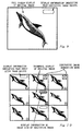
- Step S126 In case where the derivative image generating button 29 is pressed down here, the MPU 21 displays a derivative image generation mark on each of the thumbnail images at the focus positions, as shown in Fig. 10. Further, the MPU 21 adds the frame number of this focus position in a derivative image generation schedule list which is prepared on an internal memory. After this operation, the MPU 21 shifts its operation back to Step S125.
- Step S127 The MPU 21 determines the user's operation to the cross button 23.
- Step S128 If the user presses the down key 23b down here, the MPU 21 shifts its operation to Step S128.
- Step S128 The MPU 21 searches for the derivative image of the original image at the focus position, and displays as information image size of this derivative image on the thumbnail image at the focus position (refer to Fig. 10).
- the MPU 21 displays the image sizes of the derivative images in sequence every time the down key 23b is pressed down.
- Step S129 When the right key 23d is pressed down, the MPU 21 moves the focus position forward by one frame.
- Step S130 In accordance with such shift in the focus position, the MPU 21 determines whether or not the focus position shifts to the outside of a thumbnail display range.
- Step S131 When the enter key 29a is pressed down, the MPU 21 overlappingly displays the following confirmation menu on the liquid crystal display unit 31. Header "Generate a derivative image?" Option 1 ⁇ Yes (default option) Option 2 ⁇ No Option 3 ⁇ Change reduction size
- Step S132 The MPU 21 monitors the user's operation to the cross button 23 to receive the selection from the above options 1 ⁇ to 3 ⁇ .
- the MPU 21 cancels generating a new derivative image and shifts its operation back to Step S125.
- Step S133 The MPU 21 additionally displays the following confirmation menu on the display image on the liquid crystal display unit 31. Header "Change reduction size" Option 1 ⁇ 640 x 480 (default at the shipping time) Option 2 ⁇ 320 x 240 Option 3 ⁇ 160 x 120 Option 4 ⁇ 96 x 72
- Step S134 The MPU 21 monitors the user's operation to the cross button 23 to receive the selection of the image size (reduction size) of the derivative image. The MPU 21 uses the image size selected here as a default thereafter. After this operation, the MPU 21 shifts its operation back to Step S131.
- Step S135 The MPU 21 sequentially generates the derivative images from the original images with the generation mark (the original images listed in the derivative image generation schedule list) and sequentially records these derivative images in the memory card 19.
- the original image and the derivative image are discriminated based on the file name rule and only the original image is displayed on the liquid crystal display unit 31. This makes it possible to surely prevent the user from being confused at image management since there is no case where the original image and the derivative image being the same image are displayed together.
- thumbnail display mode only the original images are displayed and thus the original images and the derivative images are not displayed concurrently on the screen. This can surely prevent the user from being confused at the image management because the original image and the derivative image being the same image are both present on the screen.
- a fourth embodiment is an embodiment of an electronic camera corresponding to the inventions of claims 15 to 19.
- the configuration of the electronic camera in the fourth embodiment is the same as that in the third embodiment (Fig. 1 and Fig. 2), and therefore, the configuration description thereof will be omitted here. Further, description on the same operations as those of the third embodiment (the operation in the thumbnail display mode and so on) will be also omitted in order to avoid repeated description.
- An imaging unit described in the claims corresponds to an image sensor 13, a timing generator 13a, an image processing unit 14, an A/D converting unit 15, and a DSP 16.
- a derivative image generating unit described in the claims corresponds to 'a function of generating a derivative image' of an MPU 21 (or the DSP 16).
- a transfer unit described in the claims corresponds to an interface 32.
- a display unit described in the claims corresponds to the MPU 21 and a liquid crystal display unit 31.
- a slide display unit described in the claims corresponds to the MPU 21 and the liquid crystal display unit 31.
- Fig. 11 is a flowchart explaining the operation performed in a full screen display mode in the fourth embodiment.
- the same step numbers are assigned to the same operations as those in the third embodiment (Fig. 7), and repeated description thereof will be omitted here.
- Step S141 The MPU 21 reads out from a memory card 19 a file property of an original image which is to be displayed, and determines whether or not this original image is set as non-display.
- the MPU 21 shifts its operation to Step S142.
- Step S103 When the original image is not set as non-display (when the display thereof is permitted), the MPU 21 shifts its operation to Step S103.
- Step S142 The MPU 21 cyclically moves a frame number which is to be displayed, by one frame forward and so controls that the original image (and a derivative image) set as non-display is not displayed on the screen. After this operation, the MPU 21 shifts its operation back to Step S102.
- Step S143 When a down key 23b is pressed down in Step S106, the MPU 21 replaces an initial letter of a file name "DSCN****.jpg" of the original image with a letter (for example, "S" or the like) according to the image size to generate a file name of the derivative image.
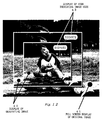
- the MPU 21 searches the memory card 19 for this derivative image. Upon finding this derivative image, the MPU 21 reads out this derivative image from the memory card 19, and displays a display 42 of this derivative image overlappingly on a full screen display 41 of the original image, as shown in Fig. 12. At this time, the MPU 21 also displays an icon 43 as information showing the image size of this derivative image.
- Fig. 12 shows a state in which the plural derivative images are displayed by this operation in a nesting way.
- Fig. 13 is a flowchart explaining the operation performed in a slide display mode in the fourth embodiment.
- Step S161 A user first turns a command dial 25 to select a reproduction mode. The user further operates a display switch button 27 as required to select the slide display mode.
- Step S162 A file name of the original image corresponding to the frame number N is generated based on the frame number N and a file name rule.
- Step S163 The MPU 21 obtains information on a file property from the memory card 19 based on the generated file name of the original image and determines whether or not the original image is set as non-display.
- the MPU 21 shifts its operation to Step S164.
- Step S165 The MPU 21 moves the frame number to be displayed by one frame forward cyclically and so controls that the original image set as non-display is not displayed on the screen. After this operation, the MPU 21 shifts its operation back to Step S162.
- Step S165 The MPU 21 reads out a compressed file of the original image from the memory card 19 based on the generated file name of the original image and stores this compressed file in a buffer memory 18. After expanding this compressed file, the DSP 16 converts the resolution thereof according the screen size of the liquid crystal display unit 31 and stores the converted file in a frame memory 30. The liquid crystal display unit 31 displays the original image (the one converted according to the screen size of a monitor screen) stored in this frame memory 30.
- Step S166 The MPU 21 determines whether or not the original image on display has a derivative image for transfer.
- the MPU 21 shifts its operation to Step S167.
- Step S168 The MPU 21 overlappingly displays an information display indicating that "a derivative image exists" on the liquid crystal display unit 31 via the frame memory 30. After such information display, the MPU 21 shifts its operation to Step S168.
- Step S168 The MPU 21 waits for the elapse of a slide display time corresponding to one frame and shifts its operation to Step S 169.
- Step S169 The MPU 21 determines whether or not the current frame number N is the last frame number in the memory card 19.
- the information display on the image size of the derivative image is displayed as shown in Fig. 12. This enables a user to appropriately distinguish the original image and the derivative image being the same image based on the information on the image size.
- the derivative images are displayed in the descending order of the image size.
- the user can appropriately distinguish the original image and the derivative image based on the display order.
- the derivative image when the original image is set as non-display, the derivative image is also set as non-display together with the original image. Therefore, the user need not separately set the derivative image as non-display, which can save the user's time and labor.
- the original image and the derivative image are discriminated based on the file name rule and only the original image is displayed in the slide display mode. Therefore, the original image and the derivative image being the same image are not redundantly and repeatedly displayed, which enables the user to look through a series of images in as short a time as possible.
- a fifth embodiment is an embodiment of an electronic camera corresponding to the inventions of claims 20 to 24.
- An imaging unit described in the claims corresponds to an image sensor 13, a timing generator 13a, an image processing unit 14, an A/D converting unit 15, and a DSP 16.
- a derivative image generating unit described in the claims corresponds to "a function of generating a derivative image" of an MPU 21 (or the DSP 16).
- a transfer setting unit described in the claims corresponds to 'a function of setting a flag on an image' of the MPU 21.
- a transfer unit described in the claims corresponds to an interface 32.
- An erase unit described in the claims corresponds to "a function of erasing an image in a memory card 19" of the MPU 21.
- Fig. 14 is a flowchart explaining the operation performed in a full screen display mode in the fifth embodiment.
- Step S201 A user first turns a command dial 25 of an electronic camera 11 to select a reproduction mode. The user further operates a display switch button 27 as required to select the full screen display mode.
- the MPU 21 selects a frame number of an image for the full screen display.
- the MPU 21 selects the last frame number (namely, a frame number most recently captured) as the frame number for the full screen display.
- Step S202 The MPU 21 generates a file name of an original image corresponding to the selected frame number based on the selected frame number and a file name rule.
- Step S203 The MPU 21 reads out a compressed file of the original image from the memory card 19 based on the generated file name and stores this compressed file in a buffer memory 18. After expanding this compressed file, the DSP 16 converts the resolution according to the screen size of a liquid crystal display unit 31, and stores this converted file in a frame memory 30. The liquid crystal display unit 31 displays on the full screen the original image (the one converted in accordance with the screen size of a monitor screen) stored in this frame memory 30. Step S204: With this full screen display, the MPU 21 determines a key operation to a cross button 23 by a user.
- Step S205 When the user presses down a left key 23c or a right key 23d here, the MPU 21 shifts its operation to Step S205.
- Step S206 When the user presses down a down key 23b, the MPU 21 shifts its operation to Step S206.
- Step S205 When the right key 23d is pressed down, the MPU 21 moves the frame number for the full screen display one forward cyclically.
- the MPU 21 moves the frame number for the full screen display one backward cyclically.
- Step S206 The MPU 21 determines whether or not the original image on display has a derivative image.
- the MPU 21 changes an initial letter of the file name of the original image from "D” to "S” to generate a file name of the derivative image.
- the MPU 21 searches the memory card 19 for this file name of the derivative image, thereby judging whether or not the original image has the derivative image.
- the MPU 21 shifts its operation to Step S207.
- Step S207 The MPU 21 reads out from the memory card 19 the derivative image which is generated from the original image on display.
- the MPU 21 displays a display 42 of this derivative image overlappingly on a full screen display 41 of the original image, as shown in Fig. 12.
- the MPU 21 also displays as information an icon 43 indicating the image size of this derivative image together.
- Fig. 12 shows a state in which the plural derivative images are displayed by this operation in a nesting way.
- Step S208 Further, the MPU 21 determines other user's key operations.
- Step S209 The MPU 21 determines whether or not the original image on display has a derivative image.
- the MPU 21 shifts its operation to Step S210.
- Step S210 The MPU 21 determines whether or not the original image on display has any print information (specification of a frame to be printed, the number of sheets to be printed, and so on) specified in DPOF (abbreviation of Digital Print Order Format) and the like.
- DPOF abbreviation of Digital Print Order Format
- the MPU 21 shifts its operation to Step S211.
- Step S212 The MPU 21 sets a flag on the original image on display. This flag is set in such a manner, for example, that the MPU 21 writes information indicating a transfer candidate in a header or the like of an image file. Another example of how the flag is set is that the MPU 21 adds an identifier (file name or the like) of the image to a transfer candidate list on an internal memory.
- Step S212 The MPU 21 sets the flag not on the original image on display but on the derivative image that the original image has.
- Step S213 The MPU 21 determines whether or not the derivative image is displayed on the screen.
- Step S214 The MPU 21 erases the original image on display from the memory card 19.
- Step S215 The MPU 21 determines whether or not the erased original image had a derivative image.
- the MPU 21 shifts its operation to Step S216.
- Step S216 The MPU 21 erases the derivative image that the original image had. Further, when the flag has been set on this derivative image, the MPU 21 removes the flag.
- Step S217 The MPU 21 moves the frame number of the original image to be displayed by one frame backward in accordance with the erase of the original image. Thereafter, the MPU 21 shifts its operation back to Step S202 and updates the full screen display.
- Step S218 The MPU 21 determines whether or not a flag is set on the derivative image displayed on the utmost front window of the screen.
- Step S219 The MPU 21 sets the flag on the original image from which this derivative image is generated. Note that when one original image has a plurality of derivative images, the MPU 21 sets the flag on a derivative image having the second largest image size next to the derivative image displayed on the utmost front window. Step S220: The MPU 21 erases from the memory card 19 the derivative image displayed on the utmost front window. Further, in a case where this derivative image has a flag, the MPU 21 removes the flag at the same time.
- Step S221 The MPU 21 determines a key operation to a derivative image generating button 29 by a user.
- the MPU 21 When the MPU 21 recognizes the user's key operation to the derivative image generating button 29 here, the MPU 21 shifts its operation to Step S222.
- Step S222 The MPU 21 reads out from the memory card 19 the compressed file of the original image currently displayed and stores this compressed file in the buffer memory 18.
- the DSP 16 expands this compressed file to develop the original image stored in the buffer memory 18 (incidentally, when the expanded image in Step S203 still exists in the buffer memory 18, it is preferable to use this image, thereby omitting the original image expanding operation).
- the MPU 21 (or the DSP 16) converts the resolution of this original image in the buffer memory 18 to generate a derivative image.
- the DSP 16 compresses this derivative image to, for example, about 1/16 irrespective of the compressibility of the original image.
- the MPU 21 copies header information of the original image and appends it to compressed data of the derivative image to generate a compressed file in an EXIF format.
- the MPU 21 replaces the initial letter of the file name "DSCN****.jpg" of the original image with a letter (for example, "S” or the like) according to the image size to generate a file name of the derivative image.
- the MPU 21 records thus generated file of the derivative image in the same folder as the original image in the memory card 19.
- Step S223 The MPU 21 determines whether or not the flag is set on the original image currently on display.
- Step S224 The MPU 21 removes the flag on the original image currently on display, and sets the flag on a newly generated derivative image.
- Fig. 15 is a flowchart explaining the operation performed in a thumbnail display mode.
- Step S241 The user first turns the command dial 25 of the electronic camera 11 to select the reproduction mode. The user further operates the display switch button 27 as required to select the thumbnail display mode.
- the MPU 21 determines a frame number of a focus position (an original image selected for focusing among a group of images displayed in the thumbnail display mode).
- the MPU 21 selects the last frame number (that is, a frame number most recently captured) as the frame number of the focus position.
- the MPU 21 selects a most recently reproduced frame number as the frame number of the focus position.
- Step S242 The MPU 21 generates file names of a group of original images for the thumbnail display in sequence based on the selected frame number and the file name rule.
- the MPU 21 stores these thumbnail images in the frame memory 30, and displays these thumbnail images as a list on the liquid crystal display unit 31, as shown in Fig. 16. At this time, the image at the focus position is highlighted (using a dotted frame or the like as shown in Fig. 16).
- Step S244 The MPU 21 determines whether or not the original image on the screen has a derivative image based on the file name rule. As for the original image having the derivative image, the MPU 21 displays information indicating that "a derivative image exists" on a corresponding thumbnail image, as shown in Fig. 16. Step S245: The MPU 21 determines the user's key operation to the cross button 23 in this thumbnail display state.
- Step S246 When the user presses down the down key 23b here, the MPU 21 shifts its operation to Step S246.
- the MPU 21 shifts its operation to Step S247.
- Step S246 The MPU 21 retrieves the derivative image of the original image at the focus position, and displays information on the image size of this derivative image on the thumbnail image at the focus position (refer to Fig. 16).
- the MPU 21 displays the image sizes of the derivative images in the descending order every time the down key 23b is pressed down.
- Step S247 When the right key 23d is pressed down, the MPU 21 moves the focus position by one frame forward.
- Step S248 In accordance with such shift of the focus position, the MPU 21 performs scroll shifting of a thumbnail view so as to keep the focus position within the screen.
- Step S249 The MPU 21 further determines a user's operation to other keys.
- the MPU 21 When the MPU 21 recognizes the key operation to the derivative image generating button 29 here, the MPU 21 shifts its operation to Step S250.
- Step S252 When the derivative image generating button 29 is thus pressed down, the MPU 21 displays a derivative image generation mark on the thumbnail image at the focus position. Further, the MPU 21 adds the frame number of this focus position to a derivative image generation schedule list which is prepared on the internal memory. After this operation, the MPU 21 shifts its operation back to Step S245.
- Step S251 When the erase button 29b is pressed down here, the MPU 21 displays a derivative image erase mark on the thumbnail image at the focus position. Further, the MPU 21 adds the frame number of this focus position to a derivative image erase schedule list which is prepared on the internal memory. After this operation, the MPU 21 shifts its operation back to Step S245.
- Step 252 The MPU 21 further determines the user's operation to other keys.
- Step S253 The MPU 21 determines whether or not the original image at the focus position has a derivative image.
- the MPU 21 shifts its operation to Step S254.
- Step S254 The MPU 21 determines whether or not the original image at the focus position has any print information (specification of a frame to be printed, the number of sheets to be printed, and so on) which is specified in DPOF (abbreviation of Digital Print Order Format) or the like.
- DPOF abbreviation of Digital Print Order Format
- the MPU 21 shifts its operation to Step S255.
- Step S255 The MPU 21 sets the flag on the original image at the focus position.
- Step S256 The MPU 21 sets the flag not on the original image at the focus position but on the derivative image that this original image has.
- Step S257 The MPU 21 selects the original image with the derivative image erase mark (the original image listed in the derivative image generation schedule list) and erases this original image together with the derivative image. Note that when the derivative image has the flag, the MPU 21 removes this flag as well.
- Step S258 The MPU 21 selects the original images with the derivative image generation mark (the original images listed in the derivative image generation schedule list) to generate the derivative images in sequence and records them in sequence on the memory card 19. Note that when the original image has the flag, the MPU 21 removes the flag from the original image and sets the flag on a newly generated derivative image.
- the user first connects the interface 32 of the electronic camera 11 to an external transfer destination via an appropriate transfer route (a cable, a wireless LAN, an Internet terminal, and the like).
- an appropriate transfer route a cable, a wireless LAN, an Internet terminal, and the like.
- the user turns a command dial 25 in this state to set the electronic camera 11 in a transfer mode.
- the MPU 21 waits for a user's operation to a transfer button 28 according to such a transfer mode.
- the MPU 21 selects a file of an image having the flag, and transfers this image to the external transfer destination according to a predetermined protocol.
- the electronic camera 11 removes the flag from the original image and sets the flag on the derivative image (refer to Steps S222 to S224 in Fig. 14 and Step 258 in Fig. 15).
- the electronic camera 11 does not set the flag on this original image but sets the flag on the derivative image (refer to Steps S209 to S212 in Fig. 14 and Steps S253 to S256 in Fig. 15).
- the derivative image generated from this original image is erased, and further, the flag on this derivative image is also removed (refer to Steps S214 to S216 in Fig. 14 and Step S257 in Fig. 15). Consequently, the removal of the flag of the derivative image and the erase of the derivative image can be carried out at the same time by only a single operation of erasing the original image. As a result, unnecessary image files in the memory card 19 can be easily erased.
- the flag when the derivative image having the flag is erased, the flag is returned to the original image from which the derivative image is generated (refer to Steps S218 to S220 in Fig. 14). Therefore, the user only needs to erase the derivative image when the user intends to transfer the original image instead of the derivative image with the flag. In this case, the flag need not be newly set on the original image, which makes it possible to facilitate the operation of the electronic camera 11.
- the flag is set on the original image irrespective of existence or nonexistence of the derivative image (refer to Steps S210 to S211 in Fig. 14 and Steps S254 to S255 in Fig. 15).
- the original image is more suitable than the derivative image in view of image quality because the original image has abundant image information compared to the derivative image with reduced data capacity.
- the original image is preferentially given the flag even when it has derivative images. This results in enhancing the print image quality with reliability when the images are used for printing purpose at the external transfer destination.
- the resolution of the original image is reduced to generate the derivative image.
- the present invention is not to be limited thereto.
- the derivative image is generated by reducing the color of the original image.
- the use of the file name rule and the hierarchical folders establishes the associations between the original image and the derivative image.
- the present invention is not to be limited thereto.
- the file associations between the original image and the derivative image may be recorded by using data such as header information of files and file management information on a recording medium.
- the original image and the derivative image may be discriminated by use of, for example, header information of files, file management information, image size, or the like.
Landscapes
- Engineering & Computer Science (AREA)
- Multimedia (AREA)
- Signal Processing (AREA)
- Television Signal Processing For Recording (AREA)
- Studio Devices (AREA)
Abstract
Description
Step S1: When a user presses down the down key 23b, the
Step S2: The
Step 3: The
Step S4: The
Header "Generate a derivative image?"
Step S5: The
Step S6: The
Header "Change reduction size"
Step S7: The
Step S8: The
Step S9: The
Header "A derivative image already generated. Overwrite?"
Step S10: The
Step 11: In the case of the reproduction mode, the
Step S12: The
Step S13: The
Step S14: The
Step S19: When the original image as the object of the manipulation is selected, the
Step S20: Next, the
Step S21: When the original image as the object of the manipulation has a derivative image, the
Step S22: The
Step S23: When the user selects a file erase command to the original image, the
Step S24: The
Step S25: When the user selects a file transfer command to the original image, the
Step S27: When the user selects a protect command for the original image, the
Step S28: The
Step S29: When the user selects an erase command to only the original image, the
Step S30: The
Step S40: A user first operates a
Step S41: The
Step S42: The
Step S43: The
Step S44: The
Step S45: The
Step S46: The
Step S47: The
Step S48: The
Step S49: The
Step S50: The
Step S51: The
Step S52: The
Step S101: A user turns a
Step S102: The
Step S103: The
Step S104: The
Step S105: The
Step S106: The
Step S107: If the right key 23d is pressed down here, the
Step S108: The
Header "Generate a derivative image?"
Step S109: The
Step S110: The
Header "Change reduction size"
Step S111: The
Step S112: The
Step S121: The user turns the
Step S122: Based on the selected frame number and the file name rule, file names of the group of the original images for the thumbnail display are generated.
Step S123: The
Step S124: The
Step S125: The
Step S126: In case where the derivative
Step S127: The
Step S128: The
Step S129: When the right key 23d is pressed down, the
Step S130: In accordance with such shift in the focus position, the
Step S131: When the enter key 29a is pressed down, the
Header "Generate a derivative image?"
Step S132: The
Step S133: The
Header "Change reduction size"
Step S134: The
Step S135: The
Step S141: The
Step S142: The
Step S143: When a down key 23b is pressed down in Step S106, the
Step S161: A user first turns a
Step S162: A file name of the original image corresponding to the frame number N is generated based on the frame number N and a file name rule.
Step S163: The
Step S164: The
Step S165: The
Step S166: The
Step S167: The
Step S168: The
Step S169: The
Step S201: A user first turns a
Step S202: The
Step S203: The
Step S204: With this full screen display, the
Step S205: When the right key 23d is pressed down, the
Step S206: The
Step S207: The
Step S208: Further, the
Step S209: The
Step S210: The
Step S211: The
Step S212: The
Step S213: The
Step S214: The
Step S215: The
Step S216: The
Step S217: The
Step S218: The
Step S219: The
Step S220: The
Step S221: The
Step S222: The
Step S223: The
Step S224: The
Step S241: The user first turns the
Step S242: The
Step S243: The
Step S244: The
Step S245: The
Step S246: The
Step S247; When the right key 23d is pressed down, the
Step S248: In accordance with such shift of the focus position, the
Step S249: The
Step S250: When the derivative
Step S251: When the erase button 29b is pressed down here, the
Step 252: The
Step S253: The
Step S254: The
Step S255: The
Step S256: The
Step S257: The
Step S258: The
Claims (24)
- An electronic camera comprising:an imaging unit for capturing a subject to generate an original image;a derivative image generating unit for reducing resolution or color of the original image to generate derivative image(s) which is/are used for transfer;a recording unit for recording the original image and the derivative image thereon such that the original image and the derivative image get associated with each other; anda transfer unit for transferring the derivative image recorded on said recording unit to an external transfer destination.
- The electronic camera according to claim 1, wherein
said recording unit has a folder in which the original image is recorded, and lower folders being under said folder hierarchically and in which the derivative images are separately recorded depending on their respective image sizes, in order to manage the original image and the derivative images in a hierarchical manner. - The electronic camera according to claim 1, wherein:said transfer unit obtains information on said external transfer destination from said external transfer destination or a user; andsaid derivative image generating unit determines an image format in accordance with the information on said external transfer destination to generate the derivative image according to said image format.
- The electronic camera according to claim 1, further comprising
an erase control unit for receiving an erase command for the original image from a user, wherein
said recording unit erases the original image in compliance with said erase command, and retrieves and erases the recorded derivative image which is associated with the erased original image. - The electronic camera according to claim 1, wherein
said recording unit erases the derivative image which has been transferred to exterior by said transfer unit. - The electronic camera according to claim 1, further comprising
a storage space monitoring unit for determining an available storage space of said recording unit and finding a shortage in the available storage space, wherein
said recording unit erases all or a part of the derivative images when said storage space monitoring unit finds the shortage in the storage space. - The electronic camera according to claim 1, further comprising
a transfer control unit for receiving a file transfer command for the original image from a user, wherein
said recording unit file-transfers the original image in compliance with said file transfer command, and retrieves and file-transfers the recorded derivative image which is associated with the original image. - The electronic camera according to claim 1, further comprising
a protect control unit for receiving a protect command for the original image from a user, wherein
said recording unit sets a protect attribute on the original image in compliance with said protect command, and retrieve the recorded derivative image which is associated with the original image to set a protect attribute on the derivative image. - The electronic camera according to claim 1, further comprising
an original image erase control unit for receiving only an erase command for the original image from a user, wherein
said recording unit erases the original image in compliance with said erase command, and retrieves the recorded derivative image which is associated with the original image and upgrade the retrieved derivative image to the original image. - The electronic camera according to claim 1, wherein:said imaging unit selectively has a moving image capture mode in which a subject is captured to generate the original image as a moving image; andsaid derivative image generating unit generates the derivative image of the original image captured in said moving image capture mode (namely, the moving image), by reducing resolution or color of one frame of the original image captured in said moving image capture mode.
- The electronic camera according to claim 1, wherein:said imaging unit selectively has a continuous capture mode in which a subject is captured to generate the original image as continuous static images; andsaid derivative image generating unit generates the derivative image (namely, a plurality of static images) of the original image captured in said continuous capture mode (namely, a plurality of static images), by reducing resolution or color of each frame of the original image captured in said moving image capture mode.
- The electronic camera according to claim 1, further comprising
a thumbnail generating unit for generating a thumbnail image for thumbnail display from the original image and appending the generated thumbnail image to the original image, wherein
said thumbnail generating unit does not append said thumbnail image to the original image when the number of pixels of said thumbnail image is equal to or larger than the number of pixels of the derivative image. - An electronic camera, comprising:an imaging unit for capturing a subject to generate an original image;a derivative image generating unit for reducing resolution or color of the original image to generate derivative image(s) which is/are used for transfer;a recording unit for recording the original image and the derivative image thereon;a transfer unit for transferring the derivative image recorded on said recording unit to an external transfer destination; anda control unit for erasing from said recording unit the derivative image which has been transferred to exterior by said transfer unit.
- The electronic camera according to claim 1, further comprising
a display unit displaying an image or information on the image, wherein
said display unit discriminates between the original image and the derivative image and decides the derivative image as non-display. - The electronic camera according to claim 1, further comprising
a display unit displaying an image or information on the image, wherein
upon displaying the derivative image, said display unit displays information on an image size of the derivative image. - The electronic camera according to claim 1, further comprising
a display unit displaying an image or information on the image, wherein:said display unit displays the derivative image when a user performs a predetermined operation during display of the original image; andwhen a plurality of derivative images generated from a same original image are present, said display unit displays the plurality of derivative images in the order of their image sizes in compliance with the user's predetermined operation. - The electronic camera according to claim 1, further comprising
a display unit displaying an image or information on the image, wherein
when deciding the original image as non-display, said display unit also decides, as non-display, the derivative image generated from the non-display original image. - The electronic camera according to claim 1, further comprising
a display unit displaying an image or information on the image, wherein
said display unit discriminates between the original image and the derivative image, and does not display the original image and the derivative image on a screen at the same time. - The electronic camera according to claim 1, further comprising
a slide display unit automatically displaying a plurality of images in sequence, wherein
said slide display unit separates said plurality of images into original image(s) and derivative image(s) to automatically display either of the original image (s) and derivative image(s). - The electronic camera according to claim 1, further comprising
a transfer setting unit setting a flag on an image designated by a user's input, the flag indicating a transfer candidate of said transfer unit, wherein:said transfer unit has a function of transferring the original image in addition to a function of transferring the derivative image; andwhen generating the derivative image from the original image having the flag set, said derivative image generating unit removes the flag from the original image and sets the flag on the generated derivative image. - The electronic camera according to claim 1, further comprising
a transfer setting unit setting a flag on an image designated by a user's input, the flag indicating a transfer candidate of said transfer unit, wherein:said transfer unit has a function of transferring the original image in addition to a function of transferring the derivative image;when an original image designated by the user's input has a derivative image, said transfer setting unit sets the flag not on the original image but on the derivative image. - The electronic camera according to claim 1, wherein further comprising:a transfer setting unit setting a flag on an image designated by a user's input, the flag indicating a transfer candidate of said transfer unit; andan erase unit erasing an image designated by a user's input, wherein:said transfer unit has a function of transferring the original image in addition to a function of transferring the derivative image;in response to erase of the original image, said transfer setting unit erases the derivative image generated from the erased original image, and removes the flag of the derivative image.
- The electronic camera according to claim 1, further comprising:a transfer setting unit setting a flag on an image designated by a user's input, the flag indicating a transfer candidate of said transfer unit; andan erase unit erasing an image designated by a user's input, wherein:said transfer unit has a function of transferring the original image in addition to a function of transferring the derivative image;when the derivative image having the flag set is erased, said transfer setting unit sets the flag on its original image from which the erased derivative image has been generated.
- The electronic camera according to claim 1, further comprising
a transfer setting unit setting a flag on an image designated by user's input, the flag indicating a transfer candidate of said transfer unit, wherein:said transfer unit has a function of transferring the original image in addition to a function of transferring the derivative image;said transfer setting unit sets the flag on an original image having print information, irrespective of whether or not the original image has a derivative image.
Applications Claiming Priority (7)
| Application Number | Priority Date | Filing Date | Title |
|---|---|---|---|
| JP2001213524 | 2001-07-13 | ||
| JP2001213524A JP4608824B2 (en) | 2001-07-13 | 2001-07-13 | Electronic camera |
| JP2001216814A JP4608825B2 (en) | 2001-07-17 | 2001-07-17 | Electronic camera |
| JP2001216814 | 2001-07-17 | ||
| JP2001245954 | 2001-08-14 | ||
| JP2001245954A JP4356272B2 (en) | 2001-08-14 | 2001-08-14 | Electronic camera |
| PCT/JP2002/007111 WO2003007599A1 (en) | 2001-07-13 | 2002-07-12 | Electronic camera |
Publications (3)
| Publication Number | Publication Date |
|---|---|
| EP1429553A1 true EP1429553A1 (en) | 2004-06-16 |
| EP1429553A4 EP1429553A4 (en) | 2007-03-28 |
| EP1429553B1 EP1429553B1 (en) | 2009-09-09 |
Family
ID=27347153
Family Applications (1)
| Application Number | Title | Priority Date | Filing Date |
|---|---|---|---|
| EP02746011A Expired - Lifetime EP1429553B1 (en) | 2001-07-13 | 2002-07-12 | Electronic camera |
Country Status (5)
| Country | Link |
|---|---|
| US (3) | US20040051784A1 (en) |
| EP (1) | EP1429553B1 (en) |
| CN (1) | CN1582571A (en) |
| DE (1) | DE60233667D1 (en) |
| WO (1) | WO2003007599A1 (en) |
Families Citing this family (22)
| Publication number | Priority date | Publication date | Assignee | Title |
|---|---|---|---|---|
| JP4173709B2 (en) * | 2002-09-26 | 2008-10-29 | 富士フイルム株式会社 | Data management method, data management apparatus and program |
| JP3937322B2 (en) * | 2002-10-04 | 2007-06-27 | 埼玉日本電気株式会社 | Mobile phone, operation control method thereof, and program |
| GB2402568B (en) * | 2003-04-30 | 2006-09-06 | Braddahead Ltd | Video capture system |
| GB2402287A (en) * | 2003-04-30 | 2004-12-01 | Braddahead Ltd | Switching between multiple analogue video signals |
| JP2005286400A (en) * | 2004-03-26 | 2005-10-13 | Fuji Photo Film Co Ltd | Digital camera |
| JP4546347B2 (en) * | 2005-07-14 | 2010-09-15 | キヤノン株式会社 | Image storage device, image storage method, and control program |
| US7760269B2 (en) * | 2005-08-22 | 2010-07-20 | Hewlett-Packard Development Company, L.P. | Method and apparatus for sizing an image on a display |
| DE602006002242D1 (en) * | 2006-02-15 | 2008-09-25 | Jaycrypto Ltd | Method and device for generating initial values for a random number generator |
| JP2007312183A (en) | 2006-05-19 | 2007-11-29 | Funai Electric Co Ltd | Image display apparatus |
| EP2026565A4 (en) * | 2006-06-13 | 2010-07-07 | Panasonic Corp | IMAGE FORMING APPARATUS |
| JP4683340B2 (en) * | 2006-07-26 | 2011-05-18 | 富士フイルム株式会社 | Imaging apparatus and imaging method |
| KR101314827B1 (en) * | 2006-12-05 | 2013-10-04 | 삼성전자주식회사 | Method for controlling digital photographing apparatus, and digital photographing apparatus adopting the method |
| US20090282365A1 (en) * | 2007-02-06 | 2009-11-12 | Nikon Corporation | Image processing apparatus, image reproducing apparatus, imaging apparatus and program recording medium |
| USD609714S1 (en) * | 2007-03-22 | 2010-02-09 | Fujifilm Corporation | Electronic camera |
| KR101465668B1 (en) * | 2008-06-24 | 2014-11-26 | 삼성전자주식회사 | Terminal and his blogging method |
| JP5208057B2 (en) * | 2009-06-16 | 2013-06-12 | キヤノン株式会社 | Image processing apparatus and control method thereof |
| US9071735B2 (en) * | 2013-05-01 | 2015-06-30 | Htc Corporation | Name management and group recovery methods and systems for burst shot |
| JP5975005B2 (en) * | 2013-09-17 | 2016-08-23 | 株式会社リコー | Image processing apparatus, information processing apparatus, and image transfer method |
| US9678649B2 (en) * | 2014-05-14 | 2017-06-13 | Htc Corporation | Method for displaying photos and electronic device for using the same |
| CN105187734A (en) * | 2015-07-23 | 2015-12-23 | 柳州永旺科技有限公司 | Loading method for dynamic image and static image |
| US10516830B2 (en) * | 2017-10-11 | 2019-12-24 | Adobe Inc. | Guided image composition on mobile devices |
| US10497122B2 (en) | 2017-10-11 | 2019-12-03 | Adobe Inc. | Image crop suggestion and evaluation using deep-learning |
Family Cites Families (28)
| Publication number | Priority date | Publication date | Assignee | Title |
|---|---|---|---|---|
| US5164831A (en) * | 1990-03-15 | 1992-11-17 | Eastman Kodak Company | Electronic still camera providing multi-format storage of full and reduced resolution images |
| JP3782471B2 (en) * | 1993-04-05 | 2006-06-07 | オリンパス株式会社 | Electronic camera |
| JP4031841B2 (en) * | 1995-09-05 | 2008-01-09 | 株式会社コダックデジタルプロダクトセンター | Digital camera |
| JP3884785B2 (en) * | 1995-11-08 | 2007-02-21 | キヤノン株式会社 | Recording / reproducing apparatus, reproducing apparatus and reproducing method |
| JPH1042286A (en) * | 1996-07-19 | 1998-02-13 | Canon Inc | Image processing apparatus, method and computer readable memory device |
| JPH10164486A (en) * | 1996-10-03 | 1998-06-19 | Nikon Corp | Information processing apparatus, information processing method, and recording medium |
| US20050158015A1 (en) * | 1996-10-03 | 2005-07-21 | Nikon Corporation | Information processing apparatus, information processing method and recording medium for electronic equipment including an electronic camera |
| US6940541B1 (en) * | 1997-04-04 | 2005-09-06 | Eastman Kodak Company | Printer parameter compensation by a host camera |
| US7212229B2 (en) * | 1997-04-04 | 2007-05-01 | Eastman Kodak Company | Digital camera providing image processing for an attachable printer |
| US6937273B1 (en) * | 1997-05-28 | 2005-08-30 | Eastman Kodak Company | Integrated motion-still capture system with indexing capability |
| JP3874317B2 (en) * | 1997-05-30 | 2007-01-31 | コニカミノルタフォトイメージング株式会社 | Digital camera |
| JPH10341411A (en) * | 1997-06-09 | 1998-12-22 | Sony Corp | Camera device |
| US6522354B1 (en) * | 1997-06-09 | 2003-02-18 | Nikon Corporation | Electronic camera and method of operating an electronic camera |
| JP3375852B2 (en) * | 1997-06-13 | 2003-02-10 | 三洋電機株式会社 | Digital camera |
| KR100261607B1 (en) * | 1997-06-30 | 2000-07-15 | 이중구 | Digital Still Camera with Remote Communication |
| US6313877B1 (en) * | 1997-08-29 | 2001-11-06 | Flashpoint Technology, Inc. | Method and system for automatically managing display formats for a peripheral display coupled to a digital imaging device |
| US6552743B1 (en) * | 1998-04-08 | 2003-04-22 | Hewlett Packard Development Company, L.P. | Digital camera-ready printer |
| JP2000312307A (en) | 1999-04-28 | 2000-11-07 | Olympus Optical Co Ltd | Electronic camera control method, information processing apparatus, and recording medium storing program for implementing electronic camera control |
| JP2000341619A (en) * | 1999-05-28 | 2000-12-08 | Canon Inc | Image processing apparatus and method, and storage medium |
| WO2001003431A1 (en) * | 1999-07-05 | 2001-01-11 | Hitachi, Ltd. | Video recording method and apparatus, video reproducing method and apparatus, and recording medium |
| JP4251757B2 (en) * | 1999-10-28 | 2009-04-08 | 三洋電機株式会社 | Digital camera |
| JP2001177742A (en) * | 1999-12-20 | 2001-06-29 | Minolta Co Ltd | Electronic camera |
| JP2001197423A (en) * | 2000-01-11 | 2001-07-19 | Konica Corp | Small image display device |
| US7034880B1 (en) * | 2000-05-11 | 2006-04-25 | Eastman Kodak Company | System and camera for transferring digital images to a service provider |
| US6885395B1 (en) * | 2000-05-26 | 2005-04-26 | Eastman Kodak Company | Selectively adjusting the resolution levels or the quality levels of digital images stored in a digital camera memory |
| JP4875798B2 (en) * | 2000-12-28 | 2012-02-15 | キヤノン株式会社 | Image viewer, control method thereof, and storage medium |
| JP2002247507A (en) * | 2001-02-15 | 2002-08-30 | Konica Corp | Image processing device |
| US7116361B2 (en) * | 2001-04-30 | 2006-10-03 | Hewlett-Packard Development Company | Image storage queue adapted to store images according to archival status |
-
2002
- 2002-07-12 DE DE60233667T patent/DE60233667D1/en not_active Expired - Lifetime
- 2002-07-12 EP EP02746011A patent/EP1429553B1/en not_active Expired - Lifetime
- 2002-07-12 WO PCT/JP2002/007111 patent/WO2003007599A1/en not_active Ceased
- 2002-07-12 US US10/380,328 patent/US20040051784A1/en not_active Abandoned
- 2002-07-12 CN CNA028023749A patent/CN1582571A/en active Pending
-
2008
- 2008-02-25 US US12/071,670 patent/US20090009629A1/en not_active Abandoned
-
2010
- 2010-12-22 US US12/929,010 patent/US8547469B2/en not_active Expired - Fee Related
Also Published As
| Publication number | Publication date |
|---|---|
| CN1582571A (en) | 2005-02-16 |
| US20090009629A1 (en) | 2009-01-08 |
| US8547469B2 (en) | 2013-10-01 |
| US20040051784A1 (en) | 2004-03-18 |
| DE60233667D1 (en) | 2009-10-22 |
| US20110096199A1 (en) | 2011-04-28 |
| WO2003007599A1 (en) | 2003-01-23 |
| EP1429553A4 (en) | 2007-03-28 |
| EP1429553B1 (en) | 2009-09-09 |
Similar Documents
| Publication | Publication Date | Title |
|---|---|---|
| US8547469B2 (en) | Electronic camera | |
| JP4143956B2 (en) | Image display device and image management program | |
| US20040267793A1 (en) | File management program, file management method, file management apparatus, imaging device and recording medium | |
| EP0993737B1 (en) | A method and system for speculative decompression of compressed image data in an image capture unit | |
| JP4090254B2 (en) | Information recording device | |
| US20040179122A1 (en) | Digital camera having an improved user interface | |
| US20040179124A1 (en) | Digital camera | |
| US20030174219A1 (en) | Image pickup and recording apparatus for recording a certain image separately from other image, and an image picking up and recording method | |
| JP3623983B2 (en) | Image file recording / reproducing apparatus and method | |
| JP4168268B2 (en) | Electronics | |
| US6564282B1 (en) | Method and system for increasing storage capacity in a digital image capture device | |
| JP2001249653A (en) | Image display method and apparatus, and electronic camera | |
| JP2009044728A (en) | Data recording device and camera | |
| JP2004304619A (en) | Digital camera | |
| JP4608824B2 (en) | Electronic camera | |
| JP2004056707A (en) | Method of creating folder and program therefor | |
| JP4356272B2 (en) | Electronic camera | |
| JP2008182513A (en) | Imaging device with information writing function | |
| JP4461991B2 (en) | Image transfer apparatus and program | |
| JP2000339344A (en) | Image reading and storage device | |
| JP4608825B2 (en) | Electronic camera | |
| JP3524804B2 (en) | Image recording device | |
| JP2004254036A (en) | Digital camera | |
| JP2005159513A (en) | Digital camera and digitized file management method | |
| JP4310711B2 (en) | Information processing apparatus and recording medium |
Legal Events
| Date | Code | Title | Description |
|---|---|---|---|
| PUAI | Public reference made under article 153(3) epc to a published international application that has entered the european phase |
Free format text: ORIGINAL CODE: 0009012 |
|
| 17P | Request for examination filed |
Effective date: 20040212 |
|
| AK | Designated contracting states |
Kind code of ref document: A1 Designated state(s): AT BE BG CH CY CZ DE DK EE ES FI FR GB GR IE IT LI LU MC NL PT SE SK TR |
|
| AX | Request for extension of the european patent |
Extension state: AL LT LV MK RO SI |
|
| A4 | Supplementary search report drawn up and despatched |
Effective date: 20070226 |
|
| RIC1 | Information provided on ipc code assigned before grant |
Ipc: H04N 5/76 20060101AFI20070220BHEP |
|
| 17Q | First examination report despatched |
Effective date: 20070628 |
|
| R17C | First examination report despatched (corrected) |
Effective date: 20070628 |
|
| GRAC | Information related to communication of intention to grant a patent modified |
Free format text: ORIGINAL CODE: EPIDOSCIGR1 |
|
| GRAP | Despatch of communication of intention to grant a patent |
Free format text: ORIGINAL CODE: EPIDOSNIGR1 |
|
| GRAS | Grant fee paid |
Free format text: ORIGINAL CODE: EPIDOSNIGR3 |
|
| GRAA | (expected) grant |
Free format text: ORIGINAL CODE: 0009210 |
|
| RBV | Designated contracting states (corrected) |
Designated state(s): DE FI FR GB SE |
|
| AK | Designated contracting states |
Kind code of ref document: B1 Designated state(s): DE FI FR GB SE |
|
| REG | Reference to a national code |
Ref country code: GB Ref legal event code: FG4D |
|
| REF | Corresponds to: |
Ref document number: 60233667 Country of ref document: DE Date of ref document: 20091022 Kind code of ref document: P |
|
| REG | Reference to a national code |
Ref country code: SE Ref legal event code: TRGR |
|
| PLBE | No opposition filed within time limit |
Free format text: ORIGINAL CODE: 0009261 |
|
| STAA | Information on the status of an ep patent application or granted ep patent |
Free format text: STATUS: NO OPPOSITION FILED WITHIN TIME LIMIT |
|
| RAP2 | Party data changed (patent owner data changed or rights of a patent transferred) |
Owner name: NIKON CORPORATION |
|
| 26N | No opposition filed |
Effective date: 20100610 |
|
| REG | Reference to a national code |
Ref country code: FR Ref legal event code: PLFP Year of fee payment: 15 |
|
| REG | Reference to a national code |
Ref country code: FR Ref legal event code: PLFP Year of fee payment: 16 |
|
| REG | Reference to a national code |
Ref country code: FR Ref legal event code: PLFP Year of fee payment: 17 |
|
| PGFP | Annual fee paid to national office [announced via postgrant information from national office to epo] |
Ref country code: DE Payment date: 20190702 Year of fee payment: 18 Ref country code: SE Payment date: 20190710 Year of fee payment: 18 Ref country code: FI Payment date: 20190709 Year of fee payment: 18 |
|
| PGFP | Annual fee paid to national office [announced via postgrant information from national office to epo] |
Ref country code: GB Payment date: 20190710 Year of fee payment: 18 |
|
| PGFP | Annual fee paid to national office [announced via postgrant information from national office to epo] |
Ref country code: FR Payment date: 20200611 Year of fee payment: 19 |
|
| REG | Reference to a national code |
Ref country code: DE Ref legal event code: R119 Ref document number: 60233667 Country of ref document: DE |
|
| REG | Reference to a national code |
Ref country code: FI Ref legal event code: MAE |
|
| REG | Reference to a national code |
Ref country code: SE Ref legal event code: EUG |
|
| GBPC | Gb: european patent ceased through non-payment of renewal fee |
Effective date: 20200712 |
|
| PG25 | Lapsed in a contracting state [announced via postgrant information from national office to epo] |
Ref country code: GB Free format text: LAPSE BECAUSE OF NON-PAYMENT OF DUE FEES Effective date: 20200712 Ref country code: FI Free format text: LAPSE BECAUSE OF NON-PAYMENT OF DUE FEES Effective date: 20200712 |
|
| PG25 | Lapsed in a contracting state [announced via postgrant information from national office to epo] |
Ref country code: DE Free format text: LAPSE BECAUSE OF NON-PAYMENT OF DUE FEES Effective date: 20210202 Ref country code: SE Free format text: LAPSE BECAUSE OF NON-PAYMENT OF DUE FEES Effective date: 20200713 |
|
| PG25 | Lapsed in a contracting state [announced via postgrant information from national office to epo] |
Ref country code: FR Free format text: LAPSE BECAUSE OF NON-PAYMENT OF DUE FEES Effective date: 20210731 |