EP1429051A2 - Transmission with cones and friction ring - Google Patents
Transmission with cones and friction ring Download PDFInfo
- Publication number
- EP1429051A2 EP1429051A2 EP04006674A EP04006674A EP1429051A2 EP 1429051 A2 EP1429051 A2 EP 1429051A2 EP 04006674 A EP04006674 A EP 04006674A EP 04006674 A EP04006674 A EP 04006674A EP 1429051 A2 EP1429051 A2 EP 1429051A2
- Authority
- EP
- European Patent Office
- Prior art keywords
- bevel
- friction ring
- friction
- ring gear
- drive
- Prior art date
- Legal status (The legal status is an assumption and is not a legal conclusion. Google has not performed a legal analysis and makes no representation as to the accuracy of the status listed.)
- Withdrawn
Links
Images


Classifications
-
- F—MECHANICAL ENGINEERING; LIGHTING; HEATING; WEAPONS; BLASTING
- F16—ENGINEERING ELEMENTS AND UNITS; GENERAL MEASURES FOR PRODUCING AND MAINTAINING EFFECTIVE FUNCTIONING OF MACHINES OR INSTALLATIONS; THERMAL INSULATION IN GENERAL
- F16H—GEARING
- F16H15/00—Gearings for conveying rotary motion with variable gear ratio, or for reversing rotary motion, by friction between rotary members
- F16H15/02—Gearings for conveying rotary motion with variable gear ratio, or for reversing rotary motion, by friction between rotary members without members having orbital motion
- F16H15/04—Gearings providing a continuous range of gear ratios
- F16H15/42—Gearings providing a continuous range of gear ratios in which two members co-operate by means of rings or by means of parts of endless flexible members pressed between the first mentioned members
-
- F—MECHANICAL ENGINEERING; LIGHTING; HEATING; WEAPONS; BLASTING
- F16—ENGINEERING ELEMENTS AND UNITS; GENERAL MEASURES FOR PRODUCING AND MAINTAINING EFFECTIVE FUNCTIONING OF MACHINES OR INSTALLATIONS; THERMAL INSULATION IN GENERAL
- F16H—GEARING
- F16H37/00—Combinations of mechanical gearings, not provided for in groups F16H1/00 - F16H35/00
- F16H37/02—Combinations of mechanical gearings, not provided for in groups F16H1/00 - F16H35/00 comprising essentially only toothed or friction gearings
- F16H37/021—Combinations of mechanical gearings, not provided for in groups F16H1/00 - F16H35/00 comprising essentially only toothed or friction gearings toothed gearing combined with continuous variable friction gearing
Definitions
- the invention relates to a conical friction ring transmission according to the preamble of Claim 1.
- Such a conical friction ring gear is known from GB-PS 298 676. at this version is parallel to the axes of the bevel friction wheels on one Guide axis guided a guide member that the friction ring along the bevel friction wheels is able to lead, whereby a stepless adjustment of the Gear ratio of the conical friction ring gear is made possible.
- For the adjustment of the friction ring requires a special drive that makes the transmission complex.
- the invention has for its object such a conical friction ring gear design more powerful.
- the solution to the problem is the characterizing features of claim 1.
- the design proposed according to the invention is particularly suitable for use as a vehicle transmission in conjunction with a fluid coupling and a manual transmission for changing the direction of travel for both Front as well as for the rear wheel drive.
- Figures 1 and 2 schematically show a friction bevel gear according to the invention.
- the cage 6 consists of a frame made by two crossheads 7, 8 and two parallel axes 9, 10 received therein is formed. These axes 9,10 are parallel to the axes 1,2 and at the same time to those under the Angle ⁇ inclined generatrix of the friction bevel gears 3, 4 and carry an adjustment bridge 11 with two pins 12 pointing towards one another, on each of which a guide roller 13 is seated. The guide rollers 13 grip on both sides of the friction ring 5 and give it the necessary axial Guide.
- the center of the crosshead 7 forms a vertical axis of rotation 14, around which the entire cage 6 is pivotable.
- the lower crosshead 8 with a transverse drive 15 acting thereon, not shown and an actuator 16 connected.
- the axis of rotation 14 lies in through the axes of rotation of the friction bevel gears 3.4 certain level. You can also do this in one parallel plane or the first-mentioned plane under an acute Cut angle.
- the cage 6 If the cage 6 is pivoted through a few angular degrees, it causes Friction drive an axial adjustment of the adjusting bridge 11 and thus one Change the gear ratio of the bevel friction wheels. This is enough a tiny amount of energy.
- FIG. 3 shows a front-wheel drive for a vehicle with an inventive Bevel friction ring gearing. It essentially consists of a hydraulic one Converter or a fluid coupling 17, one of these downstream Switch unit 18, a conical friction ring gear 19i and an output 20th
- the output part of the fluid coupling 17 is seated on a shaft 21 which is also arranged a brake disc 22, which is held in the housing 23 Brake shoes 24 interacts and can be controlled electronically.
- a free-running gear 25 that is engaged with a gear 26 only partially shown and can cause reverse gear in the output 20.
- the gear 25 has crown teeth on one side, with which it fits on the shaft 21 held and axially displaceable, having an internal axial toothing Shift sleeve 27 can be engaged and activated.
- the brake is activated first 22,24 actuated, so that the subsequent gearbox is not affected by the torque surge is affected. Then the shift sleeve 27 in Figure 3 is off their neutral position shown there moves to the right and comes with a pinion 28 which is fixedly connected to the drive shaft 29 of a bevel friction wheel 30 of the bevel friction ring gear 19 is connected.
- the two bevel friction wheels 30, 31 can be different Have diameters, which may result in a gear ratio in the next Output 20 is saved.
- the bevel friction wheels 30, 31 can also be hollow be, because it only depends on their lateral surfaces.
- the friction ring 32 is in a cage 33 held at point 34 (FIG. 3) in the housing about an axis of rotation 40 arranged pivotally in the by the axes of rotation of the friction bevel gears 30.31 certain level. In order to avoid large swivel paths, lies they approximately in the middle of the axial length of the friction bevel gears 30, 31.
- the axis of rotation As mentioned above, 40 can also lie in a plane parallel to this or cut the first-mentioned plane at an acute angle.
- the friction ring can, as shown, with its axis parallel to the axes the friction bevel gears 30, 31 may be arranged. But he can also do so in the cage be held so that its axis is parallel to the generatrix of the facing one another Friction bevel gears 30, 31 are perpendicular to the outer surface the friction bevel gear is stationary.
- an adjusting spindle mounted in the housing 23 80 provided with a servomotor or not shown Magnet is connected and engages the cage 33.
- the output shaft 43 of the bevel friction wheel 31 is in a pressing device 44 added, which in turn is mounted in the housing 23 and carries output pinions 45.46.
- the pressing device 44 consists of an overlapping the output shaft 43 Extension shaft with a bevel friction wheel 31 facing Flange 47 with a radial toothing 48 that with a corresponding radial toothing cooperates on the bevel friction wheel 31.
- the radial toothing 48 causes axial pressure on the bevel friction wheel 31.
- the housing 23 between the input and output 17, 18, 20 is advantageous on the one hand and the conical friction ring gear 19 on the other hand by a partition 49 divided.
- a coolant e.g. B. silicone oil
- Traction fluids are also suitable for coolant for the conical friction ring gear or oils with ceramic powder or other solid particles.
- the friction surfaces of at least one gear part of the Conical friction ring gear e.g. the bevel friction wheels 30, 31 or the friction ring 32 from a coating of hard metal or ceramic, e.g. Titanium nitride, titanium carbon nitride, Titanium aluminum nitride or the like
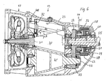
- FIG. 6 shows the application of the conical friction ring gear according to the invention with a rear wheel drive of a vehicle.
- a fluid coupling is located in front of a conical friction ring gear 19 or a hydraulic converter 17 and behind the conical friction ring gear 19 a planetary gear 50.
- the output shaft of the fluid coupling 17 also forms the shaft 51 of the upper bevel friction wheel 30, which is a lower bevel friction wheel via the friction ring 32 31 drives, on the output shaft 52 a pinion 53 is seated with a freely rotatable gearwheel seated on a transmission output shaft 53 ' 54 combs.
- the transmission output shaft 53 ' is aligned with the shaft 51 and is in this is freely rotatable.
- a pinion 55 integrally connected to the gear 54 forms the sun gear of the planetary gear 50. This meshes with planet gears 56, which are held in a planet carrier 57 which is around the transmission output shaft 53 'able to walk.
- the planet carrier 57 has a cylindrical Approach 58, which includes a ring gear 59, which with the planet gears 56 meshes and with the transmission output shaft 53 'via a spline 60 is firmly connected.
- a multi-plate clutch 61 is also provided in the planetary gear 50 the gear output shaft 53 can connect to the ring gear 59.
- the cylindrical extension 58 of the planet carrier 54 is a brake 62 assigned.
- the forward drive is switched on by actuating the multi-plate clutch 61. If the brake 62 is actuated, the planet carrier 57 is held in place and there is a change in the direction of rotation of the transmission output shaft 53, i.e. a reverse drive.
Abstract
Description
Die Erfindung betrifft ein Kegelreibringgetriebe nach dem Oberbegriff des Patentanspruches 1.The invention relates to a conical friction ring transmission according to the preamble of Claim 1.
Ein solches Kegelreibringgetriebe ist aus der GB-PS 298 676 bekannt. Bei dieser Ausführung ist parallel zu den Achsen der Kegelreibräder auf einer Führungsachse ein Führungsglied geführt, das den Reibring entlang den Kegelreibrädern zu führen vermag, wodurch eine stufenlose Verstellung des Übersetzungsverhältnisses des Kegelreibringgetriebes ermöglicht wird. Für die Verstellung des Reibringes ist ein besonderer Antrieb erforderlich, der das Getriebe aufwendig macht.Such a conical friction ring gear is known from GB-PS 298 676. at this version is parallel to the axes of the bevel friction wheels on one Guide axis guided a guide member that the friction ring along the bevel friction wheels is able to lead, whereby a stepless adjustment of the Gear ratio of the conical friction ring gear is made possible. For the adjustment of the friction ring requires a special drive that makes the transmission complex.
Der Erfindung liegt die Aufgabe zugrunde, ein derartiges Kegelreibringgetriebe leistungsfähiger auszugestalten. Die Lösung der Aufgabe besteht in den kennzeichnenden Merkmalen des Anspruches 1.The invention has for its object such a conical friction ring gear design more powerful. The solution to the problem is the characterizing features of claim 1.
Weitere vorteilhafte Weiterbildungen der Erfindung sind in den Unteransprüchen angegeben.Further advantageous developments of the invention are in the subclaims specified.
Die erfindungsgemäß vorgeschlagene Bauart eignet sich insbesondere für den Einsatz als Fahrzeuggetriebe in Verbindung mit einer Flüssigkeitskupplung und einem Schaltgetriebe für den Fahrtrichtungswechsel sowohl für den Front- als auch für den Heckantrieb. The design proposed according to the invention is particularly suitable for use as a vehicle transmission in conjunction with a fluid coupling and a manual transmission for changing the direction of travel for both Front as well as for the rear wheel drive.
Nachstehend ist die Erfindung anhand von in der Zeichnung dargestellten Ausführungsbeispielen näher erläutert. Es zeigen:
- Figur 1
- einen schematischen Querschnitt durch ein Kegelreibringgetriebe
nach der Erfindung nach der Linie I-I in
Figur 2; Figur 2- eine Draufsicht zu Figur 1;
Figur 3- einen Längsschnitt durch einen Fahrzeugantrieb für einen Frontantrieb mit einem Kegelreibringgetriebe;
Figur 4- eine andere Darstellung der Verstelleinrichtung nach einem
Schnitt IV-IV in
Figur 3; - Figur 5
- eine Einzelheit der
Figur 4 im Längsschnitt und Figur 6- einen Längsschnitt durch einen Hinterradantrieb für ein Fahrzeug mit einem Kegelreibringgetriebe.
- Figure 1
- a schematic cross section through a bevel friction ring gear according to the invention along the line II in Figure 2;
- Figure 2
- a plan view of Figure 1;
- Figure 3
- a longitudinal section through a vehicle drive for a front-wheel drive with a bevel friction ring gear;
- Figure 4
- another representation of the adjusting device according to a section IV-IV in Figure 3;
- Figure 5
- a detail of Figure 4 in longitudinal section and
- Figure 6
- a longitudinal section through a rear wheel drive for a vehicle with a bevel friction ring gear.
Die Figur 1 und 2 zeigen schematisch ein in Reibkegelgetriebe nach der Erfindung.Figures 1 and 2 schematically show a friction bevel gear according to the invention.
Es besteht im wesentlichen aus zwei auf parallelen Achsen 1,2 mit radialem
Abstand angeordneten Kegelreibrädern 3,4, die zueinander gegensinnig angeordnet
sind und gleiche Kegelwinkel β haben. Zwischen den Kegelreibrädem
3,4, ist ein, deren Zwischenraum ausfüllender Reibring 5 angeordnet,
der das Kegelreibrad 3 umgibt und in einem Käfig 6 gehalten ist.It consists essentially of two on
Der Käfig 6 besteht aus einem Rahmen, der von zwei Querhäuptern 7,8 und
zwei darin aufgenommenen, parallelen Achsen 9,10 gebildet ist. Diese Achsen
9,10 sind parallel zu den Achsen 1,2 und zugleich zu den unter dem
Winkel β geneigten Erzeugenden der Reibkegelräder 3,4 angeordnet und
tragen eine Verstellbrücke 11 mit zwei aufeinander weisenden Zapfen 12,
auf denen jeweils eine Führungsrolle 13 sitzt. Die Führungsrollen 13 greifen
beiderseits des Reibringes 5 an und geben diesem die notwendige axiale
Führung.The
Die Mitte des Querhauptes 7 bildet eine lotrechte Drehachse 14, um die der
gesamte Käfig 6 schwenkbar ist. Zu diesem Zweck ist das untere Querhaupt
8 mit einem daran angreifenden, nicht näher dargestellten Querantrieb 15
und einem Verstellmotor 16 verbunden.The center of the
Die Drehachse 14 liegt beim Ausführungsbeispiel in der durch die Drehachsen
der Reibkegelräder 3,4 bestimmten Ebene. Sie kann auch in einer hierzu
parallelen Ebene liegen oder die erstgenannte Ebene unter einem spitzen
Winkel schneiden. In the exemplary embodiment, the axis of
Wird der Käfig 6 um wenige Winkelgrade verschwenkt, so bewirkt der
Reibantrieb eine axiale Verstellung der Verstellbrücke 11 und damit eine
Änderung des Übersetzungsverhältnisses der Kegelreibräder. Hierzu genügt
ein winziger Energieaufwand.If the
Fig.3 zeigt einen Frontantrieb für ein Fahrzeug mit einem erfmdungsgemäßen
Kegelreibringgetriebe. Es besteht im wesentlichen aus einem hydraulischen
Wandler bzw. einer Flüssigkeitskupplung 17, einem dieser nachgeordneten
Schalteinheit 18, einem Kegelreibringgetriebe 19iund einem Abtrieb
20.3 shows a front-wheel drive for a vehicle with an inventive
Bevel friction ring gearing. It essentially consists of a hydraulic one
Converter or a
Der Abtriebsteil der Flüssigkeitskupplung 17 sitzt auf einer Welle 21, auf
der auch eine Bremsscheibe 22 angeordnet ist, die mit im Gehäuse 23 gehaltenen
Bremsbacken 24 zusammenwirkt und elektronisch ansteuerbar ist.The output part of the
Unmittelbar hinter der Bremsscheibe 22 sitzt ein freilaufendes Zahnrad 25,
das mit einem nur teilweise dargestellten Vorgelege 26 in Eingriff steht und
im Abtrieb 20 den Rückwärtsgang bewirken kann. Das Zahnrad 25 weist auf
einer Seite eine Kronenverzahnung auf, mit der es mit einer auf der Welle 21
gehaltenen und axial verschiebbaren, eine innere Axialverzahnung aufweisenden
Schaltmuffe 27 in Eingriff gebracht und aktiviert werden kann.Immediately behind the
Wird eine Drehrichtungsumkehr gewünscht, so wird zunächst die Bremse
22,24 betätigt, damit das nachfolgende Getriebe nicht von dem Drehmomentenstoß
beeinträchtigt wird. Sodann wird die Schaltmuffe 27 in Fig.3 aus
ihrer dort gezeigten neutralen Stellung nach rechts bewegt und gelangt mit
einem Ritzel 28 in Eingriff, das fest mit der Antriebswelle 29 eines Kegelreibrades
30 des Kegelreibringgetriebes 19 verbunden ist.If a reversal of the direction of rotation is desired, the brake is activated first
22,24 actuated, so that the subsequent gearbox is not affected by the torque surge
is affected. Then the shift sleeve 27 in Figure 3 is off
their neutral position shown there moves to the right and comes with
a
Das Kegelreibringgetriebe 19 besteht, wie in den Fig. 1 und 2 beschrieben,
aus zwei entgegengesetzt und mit radialem Abstand zueinander angeordneten
Kegelreibrädern 30,31 mit gleichem Kegelwinkel β und parallelen Achsen.
Ferner ist das obere Kegelreibrad 30 von einem Reibring 32 umschlossen,
der mit seiner inneren Mantelfläche mit dem Kegelreibrad 30 und mit
seiner äußeren Mantelfläche mit dem Kegelreibrad 31 in Reibeingriff steht.The bevel
Die beiden Kegelreibräder 30,31 können, wie dargestellt, unterschiedliche
Durchmesser haben, wodurch ggf. eine Übersetzungsstufe beim nachfolgenden
Abtrieb 20 eingespart wird.As shown, the two
Aus Gewichtsgründen können die Kegelreibräder 30,31 auch hohl ausgebildet
sein, da es lediglich auf ihre Mantelflächen ankommt.For weight reasons, the
Der Reibring 32 ist, wie auch die Fig.4 und 5 zeigen, in einem Käfig 33
gehalten, der an der Stelle 34 (Fig.3) im Gehäuse um eine Drehachse 40
schwenkbar angeordnet, die in der durch die Drehachsen der Reibkegelräder
30,31 bestimmten Ebene liegt. Um große Schwenkwege zu venneiden, liegt
sie etwa in der Mitte der axialen Länge der Reibkegelräder 30,31. Die Drehachse
40 kann, wie oben erwähnt, auch in einer hierzu parallelen Ebene liegen
oder die erstgenannte Ebene unter einem spitzen Winkel schneiden.As shown in FIGS. 4 and 5, the
Im Käfig sind zwei parallele Achsen 35,36 gehalten, deren Steigungswinkel
β zur Waagerechten gleich dem Kegelwinkel β der Kegelreibräder 30,31 ist.
Auf diesen Achsen 35,36 ist eine Verstellbrücke 37 geführt, die Ansätze 38
aufweist, an denen Führungsrollen 39 gelagert sind. Diese haben, wie Fig.5
zeigt, eine Umfangsnut 41 und umgreifen mit ihren Flanschen 42 den Reibring
32.Two
Der Reibring kann, wie dargestellt, mit seiner Achse parallel zu den Achsen
der Reibkegelräder 30,31 angeordnet sein. Er kann aber auch so im Käfig
gehalten sein, dass seine Achse parallel zur Erzeugenden der einander zugewandten
Reibkegelräder 30,31 liegt und senkrecht auf der Mantelfläche
der Reibkegelräder steht.The friction ring can, as shown, with its axis parallel to the axes
the
Für die Verstellung des Käfigs 33 ist eine im Gehäuse 23 gelagerte Verstellspindel
80 vorgesehen, die mit einem nicht dargestellten Verstellmotor oder
Magnet verbunden ist und am Käfig 33 angreift.For the adjustment of the
Bei leichter Drehung des Käfigs 33 wird der Reibring 32 um die Achse 40
gedreht, wodurch sich die relative Lage zu den Kegelrädern verändert, so
dass der Reibring 32 selbsttätig seine Position verfährt und das Übersetzungsverhältnis
des Kegelreibringgetriebes 19 verändert. When the
Die Abtriebswelle 43 des Kegelreibrades 31 ist in einer Anpresseinrichtung
44 aufgenommen, die ihrerseits im Gehäuse 23 gelagert ist und trägt Abtriebsritzel
45,46.The
Die Anpresseinrichtung 44 besteht aus einer die Abtriebswelle 43 übergreifenden
Verlängerungswelle mit einem dem Kegelreibrad 31 zugewandten
Flansch 47 mit einer Radialverzahnung 48, die mit einer entsprechenden Radialverzahnung
am Kegelreibrad 31 zusammenwirkt. Die Radialverzahnung
48 bewirkt einen axialen Druck auf das Kegelreibrad 31.The
Vorteilhaft ist das Gehäuse 23 zwischen dem An- und Abtrieb 17, 18, 20
einerseits und dem Kegelreibringgetriebe 19 andererseits durch eine Trennwand
49 abgeteilt. Damit ist es möglich, im Gehäuseteil für das Kegelreibringgetriebe
19 eine Kühlflüssigkeit ohne Schmiereigenschaften, z. B. Silikonöl,
einlaufen zu lassen, so dass der Reibwert nicht beeinflusst wird. Als
Kühlflüssigkeit für das Kegelreibringgetriebe eignen sich auch Traktionsfluide
oder Öle mit Keramikpulver oder anderen Feststoffpartikeln.The
Vorteilhaft bestehen die Reibflächen mindestens eines Getriebeteiles des
Kegelreibringgetriebes, z.B. die Kegelreibräder 30,31 oder der Reibring 32
aus einer Beschichtung aus Hartmetall oder Keramik, z.B. Titannitrid, Titancarbonnitrid,
Titan-Aluminiumnitrid oder dgl. The friction surfaces of at least one gear part of the
Conical friction ring gear, e.g. the
Die Fig.6 zeigt die Anwendung des erfindungsgemäßen Kegelreibringgetriebes bei einem Hinterradantrieb eines Fahrzeuges.6 shows the application of the conical friction ring gear according to the invention with a rear wheel drive of a vehicle.
Vor einem Kegelreibringgetriebe 19 befmdet sich eine Flüssigkeitskupplung
bzw. ein hydraulischer Wandler 17 und hinter dem Kegelreibringgetriebe 19
ein Planetengetriebe 50.A fluid coupling is located in front of a conical
Die Abtriebswelle der Flüssigkeitskupplung 17 bildet zugleich die Welle 51
des oberen Kegelreibrades 30, das über den Reibring 32 ein unteres Kegelreibrad
31 antreibt, auf dessen Abtriebswelle 52 ein Ritzel 53 sitzt, das mit
einem frei drehbaren, auf einer Getriebeabtriebswelle 53' sitzenden Zahnrad
54 kämmt. Die Getriebeabtriebswelle 53' fluchtet mit der Welle 51 und ist in
dieser frei drehbar aufgenommen.The output shaft of the
Ein mit dem Zahnrad 54 einstückig verbundenes Ritzel 55 bildet das Sonnenrad
des Planetengetriebes 50. Dieses kämmt mit Planetenzahnrädern 56,
die in einem Planetenträger 57 gehalten sind, der um die Getriebeabtriebswelle
53' zu laufen vermag. Der Planetenträger 57 weist einen zylindrischen
Ansatz 58 auf, der ein Hohlrad 59 einschließt, das mit den Plantenzahnrädem
56 kämmt und mit der Getriebeabtriebswelle 53' über eine Längsverzahnung
60 fest verbunden ist.A
Im Planetengetriebe 50 ist ferner eine Lamellenkupplung 61 vorgesehen, die
die Getriebeabtriebswelle 53 mit dem Hohlrad 59 verbinden kann. Schließlich
ist dem zylindrischen Ansatz 58 des Planetenträgers 54 eine Bremse 62
zugeordnet.A multi-plate clutch 61 is also provided in the
Durch Betätigung der Lamellenkupplung 61 wird der Vorwärtsantrieb eingeschaltet.
Wird die Bremse 62 betätigt, wird der Planetenträger 57 festgehalten
und es ergibt sich eine Drehrichtungsänderung der Getriebeabtriebswelle
53, d.h. ein Rückwärtsantrieb.The forward drive is switched on by actuating the
Claims (5)
Priority Applications (1)
| Application Number | Priority Date | Filing Date | Title |
|---|---|---|---|
| EP04006674A EP1429051A3 (en) | 1997-05-14 | 1997-05-14 | Transmission with cones and friction ring |
Applications Claiming Priority (2)
| Application Number | Priority Date | Filing Date | Title |
|---|---|---|---|
| EP04006674A EP1429051A3 (en) | 1997-05-14 | 1997-05-14 | Transmission with cones and friction ring |
| EP97107857A EP0878641B1 (en) | 1995-11-16 | 1997-05-14 | Transmission with cones and friction ring |
Related Parent Applications (2)
| Application Number | Title | Priority Date | Filing Date |
|---|---|---|---|
| EP97107857A Division EP0878641B1 (en) | 1995-11-16 | 1997-05-14 | Transmission with cones and friction ring |
| EP97107857.1 Division | 1997-05-14 |
Publications (2)
| Publication Number | Publication Date |
|---|---|
| EP1429051A2 true EP1429051A2 (en) | 2004-06-16 |
| EP1429051A3 EP1429051A3 (en) | 2005-06-01 |
Family
ID=32319753
Family Applications (2)
| Application Number | Title | Priority Date | Filing Date |
|---|---|---|---|
| EP04006674A Withdrawn EP1429051A3 (en) | 1997-05-14 | 1997-05-14 | Transmission with cones and friction ring |
| EP04014776A Expired - Lifetime EP1460310B1 (en) | 1997-05-14 | 1997-05-14 | Control method for the friction ring of a transmission with cones and friction ring |
Family Applications After (1)
| Application Number | Title | Priority Date | Filing Date |
|---|---|---|---|
| EP04014776A Expired - Lifetime EP1460310B1 (en) | 1997-05-14 | 1997-05-14 | Control method for the friction ring of a transmission with cones and friction ring |
Country Status (3)
| Country | Link |
|---|---|
| EP (2) | EP1429051A3 (en) |
| DE (2) | DE59711872D1 (en) |
| ES (2) | ES2315592T3 (en) |
Cited By (1)
| Publication number | Priority date | Publication date | Assignee | Title |
|---|---|---|---|---|
| EP2687753A3 (en) * | 2004-08-06 | 2015-03-11 | Ulrich Rohs | Friction ring-type transmission with two roller bodies with a gap between them |
Citations (1)
| Publication number | Priority date | Publication date | Assignee | Title |
|---|---|---|---|---|
| GB298676A (en) | 1927-07-15 | 1928-10-15 | Charles George Garrard | Improvements in and relating to variable speed gearing |
Family Cites Families (10)
| Publication number | Priority date | Publication date | Assignee | Title |
|---|---|---|---|---|
| FR615350A (en) * | 1900-01-01 | |||
| GB191308908A (en) * | 1913-04-16 | 1914-04-09 | Philip Alfred Charles Davies | A Variable Speed Gear for Motor Vehicles. |
| DE434153C (en) * | 1922-07-28 | 1926-09-20 | Wilhelm Stoeckicht Dipl Ing | Friction gear change transmission |
| CH147713A (en) * | 1930-03-17 | 1931-06-15 | Hauser Emil | Friction gear change gear with a movable and resistant pressure ring arranged between the friction surfaces. |
| US2178859A (en) * | 1937-06-25 | 1939-11-07 | Robert M Jett | Power transmission mechanism |
| US2847861A (en) * | 1953-06-23 | 1958-08-19 | Zenas V Weisel | Variable speed transmission |
| US3225617A (en) * | 1961-01-09 | 1965-12-28 | James R Young | Variable ratio friction transmission and control system therefor |
| US4577523A (en) * | 1983-11-28 | 1986-03-25 | Dow Corning Corporation | Silicone traction fluids |
| DE3835052A1 (en) * | 1987-10-21 | 1989-05-03 | Barmag Barmer Maschf | Frictional element gearing |
| JP2809448B2 (en) * | 1989-10-23 | 1998-10-08 | 出光興産株式会社 | Fluid for traction drive |
-
1997
- 1997-05-14 EP EP04006674A patent/EP1429051A3/en not_active Withdrawn
- 1997-05-14 EP EP04014776A patent/EP1460310B1/en not_active Expired - Lifetime
- 1997-05-14 ES ES04014776T patent/ES2315592T3/en not_active Expired - Lifetime
- 1997-05-14 ES ES97107857T patent/ES2227634T3/en not_active Expired - Lifetime
- 1997-05-14 DE DE59711872T patent/DE59711872D1/en not_active Expired - Lifetime
- 1997-05-14 DE DE59712971T patent/DE59712971D1/en not_active Expired - Lifetime
Patent Citations (1)
| Publication number | Priority date | Publication date | Assignee | Title |
|---|---|---|---|---|
| GB298676A (en) | 1927-07-15 | 1928-10-15 | Charles George Garrard | Improvements in and relating to variable speed gearing |
Cited By (3)
| Publication number | Priority date | Publication date | Assignee | Title |
|---|---|---|---|---|
| EP2687753A3 (en) * | 2004-08-06 | 2015-03-11 | Ulrich Rohs | Friction ring-type transmission with two roller bodies with a gap between them |
| US9316293B2 (en) | 2004-08-06 | 2016-04-19 | Ulrich Rohs | Friction-ring transmission having two roller bodies spaced apart from one another by a gap |
| US9638295B2 (en) | 2004-08-06 | 2017-05-02 | Ulrich Rohs | Friction-ring transmission having two roller bodies spaced apart from one another by a gap |
Also Published As
| Publication number | Publication date |
|---|---|
| DE59712971D1 (en) | 2008-11-20 |
| EP1460310A3 (en) | 2005-06-01 |
| EP1460310A2 (en) | 2004-09-22 |
| DE59711872D1 (en) | 2004-09-30 |
| ES2227634T3 (en) | 2005-04-01 |
| EP1460310B1 (en) | 2008-10-08 |
| EP1429051A3 (en) | 2005-06-01 |
| ES2315592T3 (en) | 2009-04-01 |
Similar Documents
| Publication | Publication Date | Title |
|---|---|---|
| EP0878641B1 (en) | Transmission with cones and friction ring | |
| DE3001784C2 (en) | Transmission arrangement for vehicles | |
| EP2018492B1 (en) | Transmission device for distributing a drive torque to at least two output shafts | |
| AT503359B1 (en) | TRANSMISSION MODULE FOR VARIABLE TORQUE DISTRIBUTION | |
| EP1859180B1 (en) | Differential transmission unit featuring active controlling of the moment distribution | |
| EP0175674B1 (en) | Transmission arrangement for motor vehicles | |
| EP3027455B1 (en) | Drive train of a motor vehicle | |
| EP0857267B1 (en) | Motor vehicle gearbox with infinitely variable reduction ratio | |
| DE10249485A1 (en) | Power split transmission | |
| DE10324362A1 (en) | Gear for driving a rotary tube | |
| DE3710582A1 (en) | Permanent four wheel drive for a motor vehicle | |
| EP1574316A1 (en) | Drive for a twin-screw extruder | |
| DE1630852C3 (en) | Drive block for vehicles consisting of an internal combustion engine and a hydrodynamic-mechanical transmission | |
| DE4425411A1 (en) | Infinitely variable contact transmission for rear wheel drive vehicles | |
| DE60121769T2 (en) | GEAR DRIVES | |
| DE102006022176A1 (en) | Transmission device for distributing a drive torque to at least two output shafts | |
| DE102006022174A1 (en) | Transmission device for distributing drive torque to two output shafts, has planetary gear sets that are provided between differential cage of differential and output of each side | |
| DE102004003691B4 (en) | Cone Ring Transmission | |
| WO1999010236A1 (en) | Gearbox with torque division, in particular for a helicopter rotor drive | |
| EP1429051A2 (en) | Transmission with cones and friction ring | |
| DE102007031011B4 (en) | Powertrain for a motor vehicle | |
| DE19549804B4 (en) | Variable speed drive with friction ring connecting opposed-conical rotors - has minimally-sized actuator to cant ring either way, causing axial displacement to increase or decrease ratio automatically, optionally in assembly with torque converter, epicyclic reversing gear and brake band | |
| DE102004003716A1 (en) | Cone Ring Transmission | |
| DE112018001076B4 (en) | Infinitely variable friction gear with cone planets | |
| DE102004039266B4 (en) | Motor vehicle e.g. passenger vehicle, front wheel driving unit, has slip-controlled coupling for driving torque distribution on both differentials integrated in mid axial differential, over which two units of mid differential are coupled |
Legal Events
| Date | Code | Title | Description |
|---|---|---|---|
| PUAI | Public reference made under article 153(3) epc to a published international application that has entered the european phase |
Free format text: ORIGINAL CODE: 0009012 |
|
| AC | Divisional application: reference to earlier application |
Ref document number: 0878641 Country of ref document: EP Kind code of ref document: P |
|
| AK | Designated contracting states |
Kind code of ref document: A2 Designated state(s): DE ES FR GB IT SE |
|
| PUAL | Search report despatched |
Free format text: ORIGINAL CODE: 0009013 |
|
| AK | Designated contracting states |
Kind code of ref document: A3 Designated state(s): DE ES FR GB IT SE |
|
| 17P | Request for examination filed |
Effective date: 20051104 |
|
| AKX | Designation fees paid |
Designated state(s): DE ES FR GB IT SE |
|
| 17Q | First examination report despatched |
Effective date: 20060321 |
|
| STAA | Information on the status of an ep patent application or granted ep patent |
Free format text: STATUS: THE APPLICATION IS DEEMED TO BE WITHDRAWN |
|
| 18D | Application deemed to be withdrawn |
Effective date: 20120712 |