EP1428756A1 - Tablet feeder - Google Patents
Tablet feeder Download PDFInfo
- Publication number
- EP1428756A1 EP1428756A1 EP02762802A EP02762802A EP1428756A1 EP 1428756 A1 EP1428756 A1 EP 1428756A1 EP 02762802 A EP02762802 A EP 02762802A EP 02762802 A EP02762802 A EP 02762802A EP 1428756 A1 EP1428756 A1 EP 1428756A1
- Authority
- EP
- European Patent Office
- Prior art keywords
- gear
- section
- rotor
- tablet
- gears
- Prior art date
- Legal status (The legal status is an assumption and is not a legal conclusion. Google has not performed a legal analysis and makes no representation as to the accuracy of the status listed.)
- Withdrawn
Links
Images



Classifications
-
- B—PERFORMING OPERATIONS; TRANSPORTING
- B65—CONVEYING; PACKING; STORING; HANDLING THIN OR FILAMENTARY MATERIAL
- B65B—MACHINES, APPARATUS OR DEVICES FOR, OR METHODS OF, PACKAGING ARTICLES OR MATERIALS; UNPACKING
- B65B9/00—Enclosing successive articles, or quantities of material, e.g. liquids or semiliquids, in flat, folded, or tubular webs of flexible sheet material; Subdividing filled flexible tubes to form packages
- B65B9/06—Enclosing successive articles, or quantities of material, in a longitudinally-folded web, or in a web folded into a tube about the articles or quantities of material placed upon it
- B65B9/08—Enclosing successive articles, or quantities of material, in a longitudinally-folded web, or in a web folded into a tube about the articles or quantities of material placed upon it in a web folded and sealed transversely to form pockets which are subsequently filled and then closed by sealing
-
- A—HUMAN NECESSITIES
- A61—MEDICAL OR VETERINARY SCIENCE; HYGIENE
- A61J—CONTAINERS SPECIALLY ADAPTED FOR MEDICAL OR PHARMACEUTICAL PURPOSES; DEVICES OR METHODS SPECIALLY ADAPTED FOR BRINGING PHARMACEUTICAL PRODUCTS INTO PARTICULAR PHYSICAL OR ADMINISTERING FORMS; DEVICES FOR ADMINISTERING FOOD OR MEDICINES ORALLY; BABY COMFORTERS; DEVICES FOR RECEIVING SPITTLE
- A61J3/00—Devices or methods specially adapted for bringing pharmaceutical products into particular physical or administering forms
- A61J3/06—Devices or methods specially adapted for bringing pharmaceutical products into particular physical or administering forms into the form of pills, lozenges or dragees
-
- B—PERFORMING OPERATIONS; TRANSPORTING
- B65—CONVEYING; PACKING; STORING; HANDLING THIN OR FILAMENTARY MATERIAL
- B65B—MACHINES, APPARATUS OR DEVICES FOR, OR METHODS OF, PACKAGING ARTICLES OR MATERIALS; UNPACKING
- B65B35/00—Supplying, feeding, arranging or orientating articles to be packaged
- B65B35/06—Separating single articles from loose masses of articles
- B65B35/08—Separating single articles from loose masses of articles using pocketed conveyors
-
- B—PERFORMING OPERATIONS; TRANSPORTING
- B65—CONVEYING; PACKING; STORING; HANDLING THIN OR FILAMENTARY MATERIAL
- B65B—MACHINES, APPARATUS OR DEVICES FOR, OR METHODS OF, PACKAGING ARTICLES OR MATERIALS; UNPACKING
- B65B5/00—Packaging individual articles in containers or receptacles, e.g. bags, sacks, boxes, cartons, cans, jars
- B65B5/10—Filling containers or receptacles progressively or in stages by introducing successive articles, or layers of articles
- B65B5/101—Filling containers or receptacles progressively or in stages by introducing successive articles, or layers of articles by gravity
- B65B5/103—Filling containers or receptacles progressively or in stages by introducing successive articles, or layers of articles by gravity for packaging pills or tablets
-
- B—PERFORMING OPERATIONS; TRANSPORTING
- B65—CONVEYING; PACKING; STORING; HANDLING THIN OR FILAMENTARY MATERIAL
- B65B—MACHINES, APPARATUS OR DEVICES FOR, OR METHODS OF, PACKAGING ARTICLES OR MATERIALS; UNPACKING
- B65B65/00—Details peculiar to packaging machines and not otherwise provided for; Arrangements of such details
- B65B65/02—Driving gear
Definitions
- the present invention relates to a tablet feeder.
- a tablet feeder there has conventionally been one that is composed of a case support base on which a motor is provided and a tablet housing case attachable to and detachable from the case support base.
- This type of tablet feeder is structured such that drive of the motor rotates a rotor disposed in the tablet housing case via a plurality of gears so as to discharge tablets held in the pockets of the rotor from a discharge section.
- the above-described conventional structures require a plate spring and an elastic engagement member, which complicates the structure and causes increased costs. Moreover, in the state that the tablet housing case is attached to the case support base, force always acts upon the plate spring and the elastic engagement member, so that the long-term use thereof may disable the plate spring and the elastic engagement member from sufficiently fulfilling the roll of preventing the rotation of the gear. Furthermore, when the tablet housing case is detached from the case support base, it is not possible to avoid the rotation of the gear before the force from the plate spring and the elastic engagement member acts thereon.
- a tablet feeder characterized by driving a motor provided in a case support base, rotating a rotor disposed inside a tablet housing case via a plurality of gears, moving tablets housed in the tablet housing case to a discharge section in the state of being held in each pocket section of the rotor, and discharging the tablets from the discharge section
- the gears comprises: a drive gear that is interlocked with a rotating shaft of the motor; a driven gear that is interlocked with the rotor; and an intermediate gear composed of a first gear section that gears with the drive gear and a second gear section that gears with the driven gear, and at least a gear ratio of the second gear section to the first gear section in the intermediate gear is made small so as to prevent tablets in other pocket sections adjacent to a pocket section open to the discharge section from falling down from the discharge section when the tablet housing case is detached from the case support base.
- the driven gear can rotate only in the range smaller than that of the drive gear due to the difference in gear ratio with the second gear section. Therefore, with a simple structure having only an intermediate gear that is composed of the first gear section and the second gear section different from each other in gear ratio, it becomes possible to thoroughly prevent the tablets from falling down.
- a tablet feeder characterized by driving a motor provided in a case support base, rotating a rotor disposed inside a tablet housing case via drive transmissionmeans including a plurality of gears, moving tablets housed in the tablet housing case to a discharge section in the state of being held in each pocket section of the rotor, and discharging the tablets from the discharge section
- the drive transmission means comprises: a driven gear that is interlocked with the rotor; a worm gear that gears with the driven gear; a slide shaft that is disposed slidably along a shaft center of the worm gear and that rotates integrally with the worm gear; and a drive section that is integrated with a rotating shaft of the motor and that engages with and disengages from one end portion of the slide shaft from a shaft center direction.
- the drive section that is integrated with the rotating shaft of the motor engages with and disengages from the slide shaft from the shaft center direction, so that rotation of the worm gear is prevented. Therefore, the rotor would not rotate via the driven gear, making it possible to thoroughly prevent the tablets from falling down.
- the slide shaft is slid and engaged with the drive section by rotation of the motor. Therefore, attachment of the tablet housing case is accomplished by one smooth operation, making it possible to ensure engagement between the drive section and the slide shaft.
- Fig. 1 shows tablet feeders 1 according to the first embodiment in the state of being attached to respective case support bases 3 disposed in a cylindrical shape inside a tablet feeding apparatus 2. Tablets discharged from each of the tablet feeder 1 travel through a pathway 1a extending in the vertical direction, and are collected in a hopper 1b below and packed one by one by a packing unit 1c.
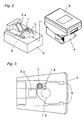
- the tablet feeder 1 has a tablet housing case 4 attachable to and detachable from the case support base 3 provided in the tablet feeding apparatus 2.
- the case support base 3 is structured such that guide sections 5 are disposed in parallel on its upper surface with a specified space therebetween. Further, in the case support base 3, there is housed a motor 6 that is subject to drive control based on a control signal from an unshown control unit. The rotating shaft of the motor 6 protrudes above the upper face of the case support base 3, and the protruded portion is integrated with a drive gear 7. As the drive gear 7, there is used, for example, a spur gear with a module of 0.8 and 13 teeth. Also in the case support base 3, there is formed a discharge pathway 3a linked to the pathway 1a, where a sensor (unshown) for detecting passing tablets is provided.
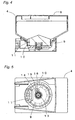
- the tablet housing case 4 has a substantially box-like shape and its upper face is comprised of a cover article 8 that is openable and closable.
- the upper face of the bottom wall of the tablet housing case 4 is shaped into a substantially circular cone, on which a rotor 9 is disposed.
- the pocket section 10 has a width and a depth that makes it possible to hold only one among housed tablets.
- a discharge port 11 is formed on the bottom wall of the tablet housing case 4.
- the discharge port 11 has a width size that makes it possible to position only one pocket section 10 of the rotor 9.
- the rotating shaft of the rotor 9 protrudes from the lower face of the bottom wall of the tablet housing case 4, and is integrated with a driven gear 13.
- a driven gear 13 there is used, for example, a spur gear having 38 teeth.
- an intermediate gear 14 is provided in a rotatable manner.
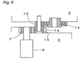
- the intermediate gear 14 is a double-tiered spur gear comprised of a first gear section 15 that gears with the drive gear 7 and a second gear section 16 that gears with the driven gear 13 when the tablet housing case 4 is attached to the case support base 3.
- the first gear section 15 has the same number of teeth as the drive gear 7, while the second gear section 16 has a number of teeth smaller than that of the driven gear 13 (12 teeth for example).
- a tablet feeder 1 housing relevant tablets is driven. More specifically, the motor 6 is driven to rotate the rotor 9, and the tablet held in each pocket section 10 is discharged in sequence from the discharge pathway 3a. A number of discharged tablets is counted by a sensor provided in the discharge pathway 3a, and the motor 6 is stopped when a specified number is reached.
- the tablets are given off from the tablet feeder 1, and when the tablets run out, the tablet housing case 4 is detached from the case support base 3 for replenishment.
- the drive gear 7 gears with the second gear section 16 of the intermediate gear 14
- the intermediate gear 14 rotates by one tooth at the maximum.
- the driven gear 13 that is connected to the rotor 9 via the first gear section 15 of the intermediate gear 14 also rotates.
- a gear ratio of the second gear section 16 to the first gear section 15 is small, and in addition, a gear ratio of the driven gear 13 to the second gear section 16 is large. Consequently, the rotating angle of the driven gear 13 is kept small.
- the drive gear 7 has 13 teeth
- the first gear section 15 of the intermediate gear 14 has 13 teeth
- the second gear section 16 has 12 teeth
- the driven gear 13 has 38 teeth as described above
- one-tooth rotation of the drive gear 7 corresponds to approx. 0.4-tooth (13/12 ⁇ 13/38) rotation of the driven gear 13. Therefore, even if the intermediate gear 14 rotates when the tablet housing case 4 is detached from the case support base 3, the rotating amount of the driven gear 13 can be kept small, and so tablets held in adj acent pocket sections 10 would not be discharged from the discharge pathway 3a through the discharge port 11. This means that attachment and detachment of the tablet housing case 4 would not cause an improper fall of the tablets.
- the gear ratio between the first gear section 15 and the second gear section 16 of the intermediate gear 14 and the gear ratio between the second gear section 16 of the intermediate gear 14 and the driven gear 13 are set different so as to control rotation of the rotor 9 upon attachment and detachment of the tablet housing case 4.
- the double-tiered intermediate gear 14 having a different gear ratio is interposed between the drive gear 7 and the driven gear 13, the rotational quantity of the rotor 9 when the tablet housing case 4 is detached from the case support base 3 in a restricted range of occupied area can be sufficiently suppressed so as to thoroughly prevent a tablet held in the pocket section 10 from falling down to the discharge pathway 3a through the discharge port 11.
- Fig. 7 shows a tablet feeder 100 according to the second embodiment.
- the tablet feeder 100 is comprised of a tablet housing case 101 attached to and detached from a case support base 3 provided in a tablet feeding apparatus 2.
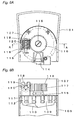
- a rotating shaft of an motor not shown protrudes along an attachment direction of the tablet housing case 101, and a drive section 102 shown in Fig. 9 is provided at its top end.
- the drive section 102 is composed of a cylindrical section 103 formed on the periphery of the top end, and a pair of first engagement protruding sections 104 formed in symmetrical positions on the inner surface thereof.
- the tablet housing case 101 is comprised of a box-shaped housing section 105, a cylindrical barrel section 106 linked to the lower part of the housing section 105, and an attachment section 107 protruding in a circular arc shape from the outer circumference of the bottom face of the barrel section 106.
- An upper aperture portion of the housing section 105 is opened and closed by a cover article 108 that rotates around a spindle 108a.
- a rotor 109 is rotatably housed in thebarrel section 106.
- the rotor 109 is formed to have a circular arc-shaped upper face, on which a recess section 110 forming a fan shape from a vertex and having a depth gradually increased toward the direction of rotation is formed in three locations at an equal angle.
- a groove-shaped pocket section 111 is formed in a plurality of locations at an equal angle.
- the pocket sections 111 are linked to each other through a circumferential groove 112, on which a partition member 114 is disposable as shown in Fig.
- the partition member 114 being inserted from a slit 113 formed on the front face of the barrel section 106.
- the partition member 114 ensures that a pocket section 111 holds only one of the tablets in the housing section 105 by preventing other tablets from the housing section 105 from entering into the pocket section 111.
- a rotating shaft 115 of the rotor 109 protrudes from the bottom face of the barrel section 106 to the inside of the attachment section 107, where the rotating shaft 115 is integrated with a given gear 116.
- a curved recess section 117 is formed on the tooth top of the given gear 116 to achieve a good gearing condition with a later-described worm gear 120.
- supporting walls 118 are formed with a specified space, which support the worm gear 120 in a rotatable manner through a slide shaft 119.
- the worm gear 120 gears with the given gear 116, and its center hole 121 has groove portions 122 formed in symmetrical positions.
- the slide shaft 119 has a collar section 123 on its one end, and second engagement protruding sections 124 are formed at quadrisected positions on the circumference thereof.
- the collar section 123 is disposed in the cylindrical section 103 formed on the drive section 102 of the motor so that the second engagement protruding sections 124 engage with the first engagement protruding sections 104 formed thereon.
- projections 125 slidably disposed in the groove portions 122 of the worm gear 120 are formed in the symmetrical positions on a central portion of the slide shaft 119.
- the worm gear 120 is attached as shown below. That is, a C-ring 126 is slidably placed between the collar section 123 and the projections 125 of the slide shaft 119, and a spring 127 is externally attached on the top end side of the slide shaft 119. Then, the top end side of the slide shaft 119 is inserted together with the spring 127 into the center hole 121 of the worm gear 120, and is passed through a tiered O-ring 128. In this point, the projections 125 of the slide shaft 119 slidably engage with the groove portions 122 of the worm gear 120. Next, a portion between the C-ring 126 and the collar section 123, and a small-diameter section 128a of the O-ring 128 are rotatably supported by a U-shaped section 118a of the supporting wall 118.
- the tablet housing case 101 is attached to the case support base 3, by which the collar section 123 of the slide shaft 119 is positioned in the cylindrical section 103 of the drive section 102, where the first engagement protruding sections 104 engage with the second engagement protruding sections 124, allowing transmission of power from the motor to the rotor 109.
- the slide shaft 119 is pushed against the spring 127.
- the worm gear 120 wouldnot rotate, and so the given gear 116 and the rotor 109 maintain their positions, preventing a tablet held in the pocket section 111 from accidentally falling down to the side of the pathway 1a. Then, when the motor is driven later, the slide shaft 119 rotates and the positions of the first engagement protruding sections 104 with respect to the second engagement protruding sections 124 are displaced, so that the slide shaft 119 is moved by the biasing force of the spring 127, which establishes engagement between the engagement protruding sections 104 and 124, thereby allowing transmission of power.
- the first engagement protruding sections 104 of the drive section 102 impart no power to the second engagement protruding sections 124 of the slide shaft 119, so that the worm gear 120 would not rotate, and so the given gear 116 and the rotor 109 maintain their position intact. Therefore, if the tablet housing case 101 is detached from the case support base 3, the rotor 109 would not rotate, and so a tablet held in the pocket section 111 would not fall down accidentally.
Landscapes
- Engineering & Computer Science (AREA)
- Mechanical Engineering (AREA)
- Health & Medical Sciences (AREA)
- Chemical & Material Sciences (AREA)
- Medicinal Chemistry (AREA)
- Life Sciences & Earth Sciences (AREA)
- Pharmacology & Pharmacy (AREA)
- Animal Behavior & Ethology (AREA)
- General Health & Medical Sciences (AREA)
- Public Health (AREA)
- Veterinary Medicine (AREA)
- Basic Packing Technique (AREA)
- Medical Preparation Storing Or Oral Administration Devices (AREA)
- Gear Transmission (AREA)
- Supply Of Fluid Materials To The Packaging Location (AREA)
Abstract
Gears are composed of a drive gear 7 that is interlocked
with the rotating shaft of a motor 6, a driven gear 13 that is
interlocked with a rotor 9, and an intermediate gear 14 made
up of a first gear section 15 that gears with the drive gear
7 and a second gear section 16 that gears with the driven gear
13. At least a gear ratio of the second gear section 16 to the
first gear section 15 of the intermediate gear 14 is made small
so as to prevent tablets in other pocket sections 10 adjacent
to a pocket section 10 open to a discharge port 11 from falling
from the discharge port 11 when a tablet housing case 4 is detached
from a case support base 3. This makes it possible to thoroughly
prevent tablets from falling down when the tablet housing case
is detached from the case support base despite a simple structure.
Description
The present invention relates to a tablet feeder.
As a tablet feeder, there has conventionally been one that
is composed of a case support base on which a motor is provided
and a tablet housing case attachable to and detachable from the
case support base. This type of tablet feeder is structured
such that drive of the motor rotates a rotor disposed in the
tablet housing case via a plurality of gears so as to discharge
tablets held in the pockets of the rotor from a discharge section.
When a tablet is supplied to a tablet housing case, the
tablet housing case should be tentatively detached from the case
support base. In this case, the rotor comes into a rotatable
state, and so the tablet housed therein might fall down.
Accordingly, in order to prevent automatic rotation of the rotor
and discharge of the tablet, there has been proposed a structure
for preventing rotation of the rotor by pressing a plate spring
and the like to the gear that is interlocked with the rotor (see
Japanese Patent Gazette No. 3040396, Japanese Patent Laid-Open
Publication No. 10-314277, and Japanese Patent Laid-Open
Publication No. 2000-43801 for reference).
Further, when the tablet housing case is detached from
the case support base, tooth bearing of the gear on the case
support base side and the tablet housing case side is changed,
which sometimes causes slight rotation of the rotor. In this
case, depending on the stop position of the rotor, tablets held
in the pockets may be discharged from the discharge section.
Accordingly, in order to prevent rotation of the rotor
when the tablet housing case is detached from the case support
base, there has been proposed a structure having an elastic
engagement member which engages with the gear that is interlocked
with the rotor to prevent the rotor from rotating when the tablet
housing case is detached from the case support base (Japanese
Patent Laid-Open Publication No. 9-323702).
However, the above-described conventional structures
require a plate spring and an elastic engagement member, which
complicates the structure and causes increased costs. Moreover,
in the state that the tablet housing case is attached to the
case support base, force always acts upon the plate spring and
the elastic engagement member, so that the long-term use thereof
may disable the plate spring and the elastic engagement member
from sufficiently fulfilling the roll of preventing the rotation
of the gear. Furthermore, when the tablet housing case is
detached from the case support base, it is not possible to avoid
the rotation of the gear before the force from the plate spring
and the elastic engagement member acts thereon.
Accordingly, it is a primary object of the present
invention to provide a tablet feeder capable of thoroughly
preventing tablets from falling down when a tablet housing case
is detached from a case support base despite a simple structure.
As a means to accomplish the above object of the present
invention, there is provided a tablet feeder characterized by
driving a motor provided in a case support base, rotating a rotor
disposed inside a tablet housing case via a plurality of gears,
moving tablets housed in the tablet housing case to a discharge
section in the state of being held in each pocket section of
the rotor, and discharging the tablets from the discharge section,
wherein
the gears comprises: a drive gear that is interlocked with a rotating shaft of the motor; a driven gear that is interlocked with the rotor; and an intermediate gear composed of a first gear section that gears with the drive gear and a second gear section that gears with the driven gear, and at least a gear ratio of the second gear section to the first gear section in the intermediate gear is made small so as to prevent tablets in other pocket sections adjacent to a pocket section open to the discharge section from falling down from the discharge section when the tablet housing case is detached from the case support base.
the gears comprises: a drive gear that is interlocked with a rotating shaft of the motor; a driven gear that is interlocked with the rotor; and an intermediate gear composed of a first gear section that gears with the drive gear and a second gear section that gears with the driven gear, and at least a gear ratio of the second gear section to the first gear section in the intermediate gear is made small so as to prevent tablets in other pocket sections adjacent to a pocket section open to the discharge section from falling down from the discharge section when the tablet housing case is detached from the case support base.
According to this structure, even if the teeth of the drive
gear presses and rotates the teeth of the first gear section
of the intermediate gear when the tablet housing case is detached
from the case support base, the driven gear can rotate only in
the range smaller than that of the drive gear due to the difference
in gear ratio with the second gear section. Therefore, with
a simple structure having only an intermediate gear that is
composed of the first gear section and the second gear section
different from each other in gear ratio, it becomes possible
to thoroughly prevent the tablets from falling down.
Further, as a means to accomplish the above object of the
present invention, there is provided a tablet feeder
characterized by driving a motor provided in a case support base,
rotating a rotor disposed inside a tablet housing case via drive
transmissionmeans including a plurality of gears, moving tablets
housed in the tablet housing case to a discharge section in the
state of being held in each pocket section of the rotor, and
discharging the tablets from the discharge section, wherein
the drive transmission means comprises: a driven gear that is interlocked with the rotor; a worm gear that gears with the driven gear; a slide shaft that is disposed slidably along a shaft center of the worm gear and that rotates integrally with the worm gear; and a drive section that is integrated with a rotating shaft of the motor and that engages with and disengages from one end portion of the slide shaft from a shaft center direction.
the drive transmission means comprises: a driven gear that is interlocked with the rotor; a worm gear that gears with the driven gear; a slide shaft that is disposed slidably along a shaft center of the worm gear and that rotates integrally with the worm gear; and a drive section that is integrated with a rotating shaft of the motor and that engages with and disengages from one end portion of the slide shaft from a shaft center direction.
According to this structure, when the tablet housing case
is attached to and detached from the case support base, the drive
section that is integrated with the rotating shaft of the motor
engages with and disengages from the slide shaft from the shaft
center direction, so that rotation of the worm gear is prevented.
Therefore, the rotor would not rotate via the driven gear, making
it possible to thoroughly prevent the tablets from falling down.
Moreover, even if the drive section and the slide shaft do not
engage with each other when the tablet housing case is attached
to the case support base, the slide shaft is slid and engaged
with the drive section by rotation of the motor. Therefore,
attachment of the tablet housing case is accomplished by one
smooth operation, making it possible to ensure engagement between
the drive section and the slide shaft.
Embodiments of the invention will now be described with
reference to the accompanying drawings.
Fig. 1 shows tablet feeders 1 according to the first
embodiment in the state of being attached to respective case
support bases 3 disposed in a cylindrical shape inside a tablet
feeding apparatus 2. Tablets discharged from each of the tablet
feeder 1 travel through a pathway 1a extending in the vertical
direction, and are collected in a hopper 1b below and packed
one by one by a packing unit 1c.
As shown in Fig. 2, the tablet feeder 1 has a tablet housing
case 4 attachable to and detachable from the case support base
3 provided in the tablet feeding apparatus 2.
As shown in Fig. 3, the case support base 3 is structured
such that guide sections 5 are disposed in parallel on its upper
surface with a specified space therebetween. Further, in the
case support base 3, there is housed a motor 6 that is subject
to drive control based on a control signal from an unshown control
unit. The rotating shaft of the motor 6 protrudes above the
upper face of the case support base 3, and the protruded portion
is integrated with a drive gear 7. As the drive gear 7, there
is used, for example, a spur gear with a module of 0.8 and 13
teeth. Also in the case support base 3, there is formed a
discharge pathway 3a linked to the pathway 1a, where a sensor
(unshown) for detecting passing tablets is provided.
As shown in Fig. 4 and Fig. 5, the tablet housing case
4 has a substantially box-like shape and its upper face is
comprised of a cover article 8 that is openable and closable.
The upper face of the bottom wall of the tablet housing case
4 is shaped into a substantially circular cone, on which a rotor
9 is disposed. On the lower face of the circular cone of the
rotor 9, groove-shaped pocket sections 10 are formed in a
plurality of locations at an equal angle. The pocket section
10 has a width and a depth that makes it possible to hold only
one among housed tablets. Moreover, a discharge port 11 is formed
on the bottom wall of the tablet housing case 4. The discharge
port 11 has a width size that makes it possible to position only
one pocket section 10 of the rotor 9. The rotating shaft of
the rotor 9 protrudes from the lower face of the bottom wall
of the tablet housing case 4, and is integrated with a driven
gear 13. As the driven gear 13, there is used, for example,
a spur gear having 38 teeth. Also on the lower face of the bottom
wall of the tablet housing case 4, an intermediate gear 14 is
provided in a rotatable manner. As shown in Fig. 6, the
intermediate gear 14 is a double-tiered spur gear comprised of
a first gear section 15 that gears with the drive gear 7 and
a second gear section 16 that gears with the driven gear 13 when
the tablet housing case 4 is attached to the case support base
3. The first gear section 15 has the same number of teeth as
the drive gear 7, while the second gear section 16 has a number
of teeth smaller than that of the driven gear 13 (12 teeth for
example).
Description will now be given of the operation of the
above-structured tablet feeder 1.
Based on prescription data, a tablet feeder 1 housing
relevant tablets is driven. More specifically, the motor 6 is
driven to rotate the rotor 9, and the tablet held in each pocket
section 10 is discharged in sequence from the discharge pathway
3a. A number of discharged tablets is counted by a sensor
provided in the discharge pathway 3a, and the motor 6 is stopped
when a specified number is reached.
Thus, the tablets are given off from the tablet feeder
1, and when the tablets run out, the tablet housing case 4 is
detached from the case support base 3 for replenishment. Here,
since the drive gear 7 gears with the second gear section 16
of the intermediate gear 14, the intermediate gear 14 rotates
by one tooth at the maximum. In this connection, the driven
gear 13 that is connected to the rotor 9 via the first gear section
15 of the intermediate gear 14 also rotates. In this case, a
gear ratio of the second gear section 16 to the first gear section
15 is small, and in addition, a gear ratio of the driven gear
13 to the second gear section 16 is large. Consequently, the
rotating angle of the driven gear 13 is kept small. For example,
in the case where the drive gear 7 has 13 teeth, the first gear
section 15 of the intermediate gear 14 has 13 teeth, the second
gear section 16 has 12 teeth, and the driven gear 13 has 38 teeth
as described above, one-tooth rotation of the drive gear 7
corresponds to approx. 0.4-tooth (13/12 × 13/38) rotation of
the driven gear 13. Therefore, even if the intermediate gear
14 rotates when the tablet housing case 4 is detached from the
case support base 3, the rotating amount of the driven gear 13
can be kept small, and so tablets held in adj acent pocket sections
10 would not be discharged from the discharge pathway 3a through
the discharge port 11. This means that attachment and detachment
of the tablet housing case 4 would not cause an improper fall
of the tablets.
It is to be noted that in the aforementioned embodiment,
the gear ratio between the first gear section 15 and the second
gear section 16 of the intermediate gear 14 and the gear ratio
between the second gear section 16 of the intermediate gear 14
and the driven gear 13 are set different so as to control rotation
of the rotor 9 upon attachment and detachment of the tablet housing
case 4. However, it is also acceptable to control the rotation
of the rotor 9 with use of the combination of at least either
one of the gear ratios and a gear ratio between the drive gear
7 and the first gear section 15 of the intermediate gear 14.
Particularly in the present embodiment, since the double-tiered
intermediate gear 14 having a different gear ratio is interposed
between the drive gear 7 and the driven gear 13, the rotational
quantity of the rotor 9 when the tablet housing case 4 is detached
from the case support base 3 in a restricted range of occupied
area can be sufficiently suppressed so as to thoroughly prevent
a tablet held in the pocket section 10 from falling down to the
discharge pathway 3a through the discharge port 11.
Fig. 7 shows a tablet feeder 100 according to the second
embodiment. Like the first embodiment, the tablet feeder 100
is comprised of a tablet housing case 101 attached to and detached
from a case support base 3 provided in a tablet feeding apparatus
2.
On the case support base 3, a rotating shaft of an motor
not shown protrudes along an attachment direction of the tablet
housing case 101, and a drive section 102 shown in Fig. 9 is
provided at its top end. The drive section 102 is composed of
a cylindrical section 103 formed on the periphery of the top
end, and a pair of first engagement protruding sections 104 formed
in symmetrical positions on the inner surface thereof.
As shown in Fig. 7, the tablet housing case 101 is comprised
of a box-shaped housing section 105, a cylindrical barrel section
106 linked to the lower part of the housing section 105, and
an attachment section 107 protruding in a circular arc shape
from the outer circumference of the bottom face of the barrel
section 106. An upper aperture portion of the housing section
105 is opened and closed by a cover article 108 that rotates
around a spindle 108a.
As shown in Fig. 8B, a rotor 109 is rotatably housed in
thebarrel section 106. The rotor 109 is formed to have a circular
arc-shaped upper face, on which a recess section 110 forming
a fan shape from a vertex and having a depth gradually increased
toward the direction of rotation is formed in three locations
at an equal angle. On the outer circumferential face of the
rotor 109, a groove-shaped pocket section 111 is formed in a
plurality of locations at an equal angle. The pocket sections
111 are linked to each other through a circumferential groove
112, on which a partition member 114 is disposable as shown in
Fig. 7, the partition member 114 being inserted from a slit 113
formed on the front face of the barrel section 106. The partition
member 114 ensures that a pocket section 111 holds only one of
the tablets in the housing section 105 by preventing other tablets
from the housing section 105 from entering into the pocket section
111. A rotating shaft 115 of the rotor 109 protrudes from the
bottom face of the barrel section 106 to the inside of the
attachment section 107, where the rotating shaft 115 is
integrated with a given gear 116. A curved recess section 117
is formed on the tooth top of the given gear 116 to achieve a
good gearing condition with a later-described worm gear 120.
On the bottom face of the barrel section 106, as shown
in Fig. 7 to Fig. 9, supporting walls 118 are formed with a
specified space, which support the worm gear 120 in a rotatable
manner through a slide shaft 119. The worm gear 120 gears with
the given gear 116, and its center hole 121 has groove portions
122 formed in symmetrical positions. The slide shaft 119 has
a collar section 123 on its one end, and second engagement
protruding sections 124 are formed at quadrisected positions
on the circumference thereof. The collar section 123 is disposed
in the cylindrical section 103 formed on the drive section 102
of the motor so that the second engagement protruding sections
124 engage with the first engagement protruding sections 104
formed thereon. Further, projections 125 slidably disposed in
the groove portions 122 of the worm gear 120 are formed in the
symmetrical positions on a central portion of the slide shaft
119.
The worm gear 120 is attached as shown below. That is,
a C-ring 126 is slidably placed between the collar section 123
and the projections 125 of the slide shaft 119, and a spring
127 is externally attached on the top end side of the slide shaft
119. Then, the top end side of the slide shaft 119 is inserted
together with the spring 127 into the center hole 121 of the
worm gear 120, and is passed through a tiered O-ring 128. In
this point, the projections 125 of the slide shaft 119 slidably
engage with the groove portions 122 of the worm gear 120. Next,
a portion between the C-ring 126 and the collar section 123,
and a small-diameter section 128a of the O-ring 128 are rotatably
supported by a U-shaped section 118a of the supporting wall 118.
In the case of the above-structured tablet feeder 100,
the tablet housing case 101 is attached to the case support base
3, by which the collar section 123 of the slide shaft 119 is
positioned in the cylindrical section 103 of the drive section
102, where the first engagement protruding sections 104 engage
with the second engagement protruding sections 124, allowing
transmission of power from the motor to the rotor 109. In this
case, if the positions of the first engagement protruding
sections 104 are aligned with the positions of the second
engagement protruding sections 124 and so a desired engagement
state is not achieved, the slide shaft 119 is pushed against
the spring 127. Consequently, the worm gear 120 wouldnot rotate,
and so the given gear 116 and the rotor 109 maintain their positions,
preventing a tablet held in the pocket section 111 from
accidentally falling down to the side of the pathway 1a. Then,
when the motor is driven later, the slide shaft 119 rotates and
the positions of the first engagement protruding sections 104
with respect to the second engagement protruding sections 124
are displaced, so that the slide shaft 119 is moved by the biasing
force of the spring 127, which establishes engagement between
the engagement protruding sections 104 and 124, thereby allowing
transmission of power.
Further, when the tablet housing case 101 is detached from
the case support base 3, the first engagement protruding sections
104 of the drive section 102 impart no power to the second
engagement protruding sections 124 of the slide shaft 119, so
that the worm gear 120 would not rotate, and so the given gear
116 and the rotor 109 maintain their position intact. Therefore,
if the tablet housing case 101 is detached from the case support
base 3, the rotor 109 would not rotate, and so a tablet held
in the pocket section 111 would not fall down accidentally.
Claims (2)
- A tablet feeder characterized by driving a motor provided in a case support base, rotating a rotor disposed inside a tablet housing case via a plurality of gears, moving tablets housed in the tablet housing case to a discharge section in the state of being held in each pocket section of the rotor, and discharging the tablets from the discharge section, wherein
the gears comprises: a drive gear that is interlocked with a rotating shaft of the motor; a driven gear that is interlocked with the rotor; and an intermediate gear composed of a first gear section that gears with the drive gear and a second gear section that gears with the driven gear, and at least a gear ratio of the second gear section to the first gear section in the intermediate gear is made small so as to prevent tablets in other pocket sections adjacent to a pocket section open to the discharge section from falling down from the discharge section when the tablet housing case is detached from the case support base. - A tablet feeder characterized by driving a motor provided in a case support base, rotating a rotor disposed inside a tablet housing case via drive transmission means including a plurality of gears, moving tablets housed in the tablet housing case to a discharge section in the state of being held in each pocket section of the rotor, and discharging the tablets from the discharge section, wherein
the drive transmission means comprises: a driven gear that is interlocked with the rotor; a worm gear that gears with the driven gear; a slide shaft that is disposed slidably along a shaft center of the worm gear and that rotates integrally with the worm gear; and a drive section that is integrated with a rotating shaft of the motor and that engages with and disengages from one end portion of the slide shaft from a shaft center direction.
Applications Claiming Priority (3)
| Application Number | Priority Date | Filing Date | Title |
|---|---|---|---|
| JP2001249341 | 2001-08-20 | ||
| JP2001249341 | 2001-08-20 | ||
| PCT/JP2002/008340 WO2003016138A1 (en) | 2001-08-20 | 2002-08-19 | Tablet feeder |
Publications (2)
| Publication Number | Publication Date |
|---|---|
| EP1428756A1 true EP1428756A1 (en) | 2004-06-16 |
| EP1428756A4 EP1428756A4 (en) | 2004-11-10 |
Family
ID=19078357
Family Applications (1)
| Application Number | Title | Priority Date | Filing Date |
|---|---|---|---|
| EP02762802A Withdrawn EP1428756A4 (en) | 2001-08-20 | 2002-08-19 | Tablet feeder |
Country Status (8)
| Country | Link |
|---|---|
| US (1) | US7131554B2 (en) |
| EP (1) | EP1428756A4 (en) |
| JP (1) | JP4249015B2 (en) |
| KR (1) | KR100821669B1 (en) |
| CN (2) | CN1251926C (en) |
| CA (1) | CA2457352A1 (en) |
| NO (1) | NO20041195L (en) |
| WO (1) | WO2003016138A1 (en) |
Cited By (2)
| Publication number | Priority date | Publication date | Assignee | Title |
|---|---|---|---|---|
| CN100493996C (en) * | 2005-02-25 | 2009-06-03 | 株式会社汤山制作所 | Tablet filling device |
| EP2759286A3 (en) * | 2013-01-23 | 2015-01-21 | Infopia Co., Ltd. | Cartridge for medication dispensing apparatus having auto locking function |
Families Citing this family (22)
| Publication number | Priority date | Publication date | Assignee | Title |
|---|---|---|---|---|
| JP2001287702A (en) * | 2000-04-11 | 2001-10-16 | Yuyama Manufacturing Co Ltd | Tablet filling apparatus |
| JP4351016B2 (en) * | 2003-10-01 | 2009-10-28 | 株式会社湯山製作所 | Tablet cassette |
| JP2006231459A (en) * | 2005-02-24 | 2006-09-07 | Yuyama Manufacturing Co Ltd | Vial carrying device and its arm |
| JP4802856B2 (en) * | 2006-05-24 | 2011-10-26 | 株式会社湯山製作所 | Tablet feeder |
| JP4910481B2 (en) | 2006-05-24 | 2012-04-04 | 株式会社湯山製作所 | Tablet filling equipment |
| US20080093372A1 (en) * | 2006-10-23 | 2008-04-24 | Milton Monroe T | Method and apparatus for sorting, counting and packaging pharmaceutical drugs and other objects |
| JP5297733B2 (en) * | 2008-09-12 | 2013-09-25 | 高園産業株式会社 | Drug container and drug dispensing device |
| US8430269B2 (en) * | 2008-09-30 | 2013-04-30 | Jvm Co., Ltd. | Tablet cassette of automatic tablet packing apparatus |
| KR101800029B1 (en) * | 2009-04-17 | 2017-11-21 | 가부시키가이샤 유야마 세이사쿠쇼 | Drug feeder and drug delivery unit |
| KR101254659B1 (en) | 2011-03-15 | 2013-04-15 | (주)제이브이엠 | Drug dispenser |
| DE102011080746A1 (en) | 2011-08-10 | 2013-02-14 | Robert Bosch Gmbh | Device for holding and positioning of pharmaceutical products designed as tablets, hard gelatin capsules or the like in a packaging installation |
| EP2703299B1 (en) | 2012-08-31 | 2016-03-30 | CareFusion Switzerland 317 Sarl | A storage and dosing station for storage and dispensing dosed quantities of solid drug portions |
| KR102114901B1 (en) * | 2013-10-02 | 2020-05-25 | (주)제이브이엠 | Medicine dispensing apparatus |
| SG11201602737PA (en) * | 2013-10-09 | 2016-05-30 | Takazono Technology Inc | Medicine filling apparatus |
| US10583979B2 (en) | 2015-10-12 | 2020-03-10 | Carefusion Germany 326 Gmbh | Storage container for drug dispensing and storage stations |
| ES2663811T3 (en) * | 2015-10-12 | 2018-04-17 | Becton Dickinson Rowa Germany Gmbh | Storage container for a medication storage and unloading station |
| CN106115017A (en) * | 2016-08-02 | 2016-11-16 | 迈为医疗技术(深圳)有限公司 | A kind of medicine box link plate quick-connect machanism for tablet Subpackaging machine |
| EP3389022A1 (en) * | 2017-04-11 | 2018-10-17 | Becton Dickinson Rowa Germany GmbH | Storage container for a storage and dispensing station |
| CN111419704B (en) * | 2020-03-31 | 2022-06-17 | 合肥工业大学 | Novel intelligent medicine box |
| US11498761B1 (en) * | 2021-06-22 | 2022-11-15 | Vmi Holland B.V. | Method for dispensing discrete medicaments, a test station for testing a feeder unit, and a method for determining a fill level of a feeder unit |
| NL2028895B1 (en) * | 2021-07-30 | 2023-02-02 | Vmi Holland Bv | Method for step dispensing discrete medicaments from a dispensing system, and method for controlling operation of a system |
| CN117228027B (en) * | 2023-10-30 | 2025-07-29 | 南京埃伯顿自动化设备有限公司 | Quick sorting equipment of traditional chinese medicine pharmacy traditional chinese medicine |
Family Cites Families (24)
| Publication number | Priority date | Publication date | Assignee | Title |
|---|---|---|---|---|
| GB537659A (en) * | 1939-12-28 | 1941-07-01 | Stotherts Ltd | Improvements in and relating to machines for delivering measured quantities of smalluniformly-shaped articles such as tablets, pills and the like |
| CN2172750Y (en) * | 1993-09-21 | 1994-07-27 | 东港市制药机械设备厂 | Automatic feeding device for tablet heat-sealing packing machine |
| JP2875203B2 (en) * | 1995-03-27 | 1999-03-31 | キヤノン株式会社 | Electrophotographic image forming apparatus, process cartridge, driving force transmitting component, and electrophotographic photosensitive drum |
| US5768658A (en) * | 1995-07-21 | 1998-06-16 | Canon Kabushiki Kaisha | Electrode member, developing apparatus, process cartridge and image forming apparatus |
| JPH09232702A (en) | 1996-02-26 | 1997-09-05 | Hitachi Telecom Technol Ltd | Printed wiring board structure |
| US6240266B1 (en) * | 1996-03-21 | 2001-05-29 | Canon Kabushiki Kaisha | Process cartridge and drum mount for photosensitive drum |
| JP3276847B2 (en) * | 1996-05-31 | 2002-04-22 | 株式会社湯山製作所 | Pill feeder |
| JP3745047B2 (en) * | 1996-09-26 | 2006-02-15 | キヤノン株式会社 | Electrophotographic image forming apparatus and process cartridge |
| JP3689504B2 (en) * | 1996-09-26 | 2005-08-31 | キヤノン株式会社 | Electrophotographic image forming apparatus |
| JP3969804B2 (en) * | 1996-09-26 | 2007-09-05 | キヤノン株式会社 | Electrophotographic image forming apparatus |
| CN2286668Y (en) * | 1997-04-01 | 1998-07-29 | 苏州工业园区华园机电有限公司 | Type-printer for capsule and tablet |
| JPH10314277A (en) | 1997-05-19 | 1998-12-02 | Takazono Sangyo Kk | Drug cassetter |
| FR2767121B1 (en) * | 1997-08-05 | 1999-10-29 | Jean Michel Chabout | DISTRIBUTOR OF DRUGS |
| JP3957885B2 (en) * | 1997-12-26 | 2007-08-15 | 東北リコー株式会社 | Paper feeder |
| JP2000066498A (en) * | 1998-08-21 | 2000-03-03 | Canon Inc | Electrophotographic image forming apparatus and process cartridge |
| JP2000103404A (en) * | 1998-09-29 | 2000-04-11 | Sanyo Electric Co Ltd | Medicine feed device |
| JP4298834B2 (en) * | 1999-01-14 | 2009-07-22 | 株式会社湯山製作所 | Tablet feeder |
| JP3645117B2 (en) * | 1999-03-16 | 2005-05-11 | 理想科学工業株式会社 | Paper feeder |
| JP3534658B2 (en) * | 1999-08-17 | 2004-06-07 | 高園産業株式会社 | Drug container for drug selective supply device for tablets etc. |
| JP2001159841A (en) * | 1999-12-01 | 2001-06-12 | Canon Inc | Developing cartridge, process cartridge, and electrophotographic image forming apparatus |
| JP3635003B2 (en) * | 2000-05-17 | 2005-03-30 | 理想科学工業株式会社 | Paper feeding device and printing device using the same |
| JP2002182446A (en) * | 2000-10-04 | 2002-06-26 | Canon Inc | Driving force transmitting component, electrophotographic photosensitive drum, process cartridge, and electrophotographic image forming apparatus |
| US6829455B2 (en) * | 2000-10-20 | 2004-12-07 | Canon Kabushiki Kaisha | Driving force transmission mechanism, image forming apparatus equipped with such a mechanism, and process unit of such an apparatus |
| JP4677093B2 (en) * | 2000-12-25 | 2011-04-27 | キヤノン株式会社 | Process cartridge |
-
2002
- 2002-08-19 CN CNB028161718A patent/CN1251926C/en not_active Expired - Fee Related
- 2002-08-19 US US10/486,897 patent/US7131554B2/en not_active Expired - Fee Related
- 2002-08-19 CA CA2457352A patent/CA2457352A1/en not_active Abandoned
- 2002-08-19 JP JP2003521079A patent/JP4249015B2/en not_active Expired - Fee Related
- 2002-08-19 KR KR1020047002084A patent/KR100821669B1/en not_active Expired - Fee Related
- 2002-08-19 EP EP02762802A patent/EP1428756A4/en not_active Withdrawn
- 2002-08-19 CN CNB2005100916540A patent/CN100391797C/en not_active Expired - Fee Related
- 2002-08-19 WO PCT/JP2002/008340 patent/WO2003016138A1/en not_active Ceased
-
2004
- 2004-03-19 NO NO20041195A patent/NO20041195L/en not_active Application Discontinuation
Cited By (3)
| Publication number | Priority date | Publication date | Assignee | Title |
|---|---|---|---|---|
| CN100493996C (en) * | 2005-02-25 | 2009-06-03 | 株式会社汤山制作所 | Tablet filling device |
| EP2759286A3 (en) * | 2013-01-23 | 2015-01-21 | Infopia Co., Ltd. | Cartridge for medication dispensing apparatus having auto locking function |
| US9211232B2 (en) | 2013-01-23 | 2015-12-15 | Infopia Co., Ltd. | Cartridge for medication dispensing apparatus having auto locking function |
Also Published As
| Publication number | Publication date |
|---|---|
| CN1743234A (en) | 2006-03-08 |
| NO20041195L (en) | 2004-05-19 |
| US20040195261A1 (en) | 2004-10-07 |
| KR20040029422A (en) | 2004-04-06 |
| JPWO2003016138A1 (en) | 2004-12-02 |
| US7131554B2 (en) | 2006-11-07 |
| CN100391797C (en) | 2008-06-04 |
| CA2457352A1 (en) | 2003-02-27 |
| CN1251926C (en) | 2006-04-19 |
| KR100821669B1 (en) | 2008-04-11 |
| JP4249015B2 (en) | 2009-04-02 |
| EP1428756A4 (en) | 2004-11-10 |
| CN1543415A (en) | 2004-11-03 |
| WO2003016138A1 (en) | 2003-02-27 |
Similar Documents
| Publication | Publication Date | Title |
|---|---|---|
| US7131554B2 (en) | Tablet feeder | |
| JP4574749B1 (en) | Drug feeder and drug dispensing device | |
| US6073799A (en) | Tablet feeder | |
| JP4298834B2 (en) | Tablet feeder | |
| US6776703B2 (en) | Coin dispensing device with aligned hoppers | |
| WO2003042042A1 (en) | Medicine feeder | |
| KR19990087901A (en) | Size change-able coin hopper apparatus | |
| JP2002186658A (en) | Tablet feeder | |
| JP6402332B2 (en) | Coin hopper | |
| JP3891633B2 (en) | Disc-shaped body feeding device | |
| JP3294602B1 (en) | Pill feeder | |
| JP6649660B2 (en) | Coin-like member delivery device | |
| JP3811577B2 (en) | Vending machine product dispensing device | |
| JP3014246B2 (en) | Coin payout device | |
| JP3891634B2 (en) | Disc-shaped body feeding device | |
| JP2002133485A (en) | Small coin hopper | |
| JP4507689B2 (en) | Coin ejector, coin payout device and game machine | |
| JP3611590B2 (en) | Variable winning device | |
| JP4539162B2 (en) | Coin dispensing device and game machine | |
| JP3851157B2 (en) | Rotating article support device and receiving device provided with the same | |
| JP2531351Y2 (en) | Ball discharging device in ball rental machine | |
| JPH0624928Y2 (en) | Coin dispensing device | |
| JP5830760B2 (en) | Medal insertion device, medal lending machine and gaming machine equipped with the same | |
| CN121317285A (en) | Tablet dispensing device and tablet packaging device | |
| JP3847228B2 (en) | Medal transport device, medal lending machine, and game machine |
Legal Events
| Date | Code | Title | Description |
|---|---|---|---|
| PUAI | Public reference made under article 153(3) epc to a published international application that has entered the european phase |
Free format text: ORIGINAL CODE: 0009012 |
|
| 17P | Request for examination filed |
Effective date: 20040316 |
|
| AK | Designated contracting states |
Kind code of ref document: A1 Designated state(s): AT BE BG CH CY CZ DE DK EE ES FI FR GB GR IE IT LI LU MC NL PT SE SK TR |
|
| A4 | Supplementary search report drawn up and despatched |
Effective date: 20040924 |
|
| 17Q | First examination report despatched |
Effective date: 20070103 |
|
| STAA | Information on the status of an ep patent application or granted ep patent |
Free format text: STATUS: THE APPLICATION IS DEEMED TO BE WITHDRAWN |
|
| 18D | Application deemed to be withdrawn |
Effective date: 20070301 |