EP1428585A1 - Dispositif porte verres destiné plus particulierement au traitement des verres optiques ou autres substrats - Google Patents
Dispositif porte verres destiné plus particulierement au traitement des verres optiques ou autres substrats Download PDFInfo
- Publication number
- EP1428585A1 EP1428585A1 EP02027942A EP02027942A EP1428585A1 EP 1428585 A1 EP1428585 A1 EP 1428585A1 EP 02027942 A EP02027942 A EP 02027942A EP 02027942 A EP02027942 A EP 02027942A EP 1428585 A1 EP1428585 A1 EP 1428585A1
- Authority
- EP
- European Patent Office
- Prior art keywords
- clamp
- glass
- bar
- glass holder
- holder device
- Prior art date
- Legal status (The legal status is an assumption and is not a legal conclusion. Google has not performed a legal analysis and makes no representation as to the accuracy of the status listed.)
- Granted
Links
- 239000011521 glass Substances 0.000 title claims abstract description 53
- 239000005304 optical glass Substances 0.000 title claims abstract description 17
- 239000000758 substrate Substances 0.000 title claims abstract description 6
- 238000011282 treatment Methods 0.000 claims abstract description 7
- 239000002184 metal Substances 0.000 claims description 8
- 230000002093 peripheral effect Effects 0.000 claims description 8
- 230000000284 resting effect Effects 0.000 claims description 2
- 241001639412 Verres Species 0.000 description 3
- 230000000694 effects Effects 0.000 description 3
- 238000004140 cleaning Methods 0.000 description 2
- 239000007788 liquid Substances 0.000 description 2
- 239000012263 liquid product Substances 0.000 description 2
- 230000003287 optical effect Effects 0.000 description 2
- 239000002966 varnish Substances 0.000 description 2
- 238000006116 polymerization reaction Methods 0.000 description 1
- 238000002791 soaking Methods 0.000 description 1
- 239000000725 suspension Substances 0.000 description 1
- 238000003466 welding Methods 0.000 description 1
Images

Classifications
-
- B—PERFORMING OPERATIONS; TRANSPORTING
- B08—CLEANING
- B08B—CLEANING IN GENERAL; PREVENTION OF FOULING IN GENERAL
- B08B11/00—Cleaning flexible or delicate articles by methods or apparatus specially adapted thereto
- B08B11/02—Devices for holding articles during cleaning
-
- B—PERFORMING OPERATIONS; TRANSPORTING
- B29—WORKING OF PLASTICS; WORKING OF SUBSTANCES IN A PLASTIC STATE IN GENERAL
- B29D—PRODUCING PARTICULAR ARTICLES FROM PLASTICS OR FROM SUBSTANCES IN A PLASTIC STATE
- B29D11/00—Producing optical elements, e.g. lenses or prisms
- B29D11/00009—Production of simple or compound lenses
-
- B—PERFORMING OPERATIONS; TRANSPORTING
- B29—WORKING OF PLASTICS; WORKING OF SUBSTANCES IN A PLASTIC STATE IN GENERAL
- B29D—PRODUCING PARTICULAR ARTICLES FROM PLASTICS OR FROM SUBSTANCES IN A PLASTIC STATE
- B29D11/00—Producing optical elements, e.g. lenses or prisms
- B29D11/00865—Applying coatings; tinting; colouring
- B29D11/00894—Applying coatings; tinting; colouring colouring or tinting
- B29D11/00903—Applying coatings; tinting; colouring colouring or tinting on the surface
-
- Y—GENERAL TAGGING OF NEW TECHNOLOGICAL DEVELOPMENTS; GENERAL TAGGING OF CROSS-SECTIONAL TECHNOLOGIES SPANNING OVER SEVERAL SECTIONS OF THE IPC; TECHNICAL SUBJECTS COVERED BY FORMER USPC CROSS-REFERENCE ART COLLECTIONS [XRACs] AND DIGESTS
- Y10—TECHNICAL SUBJECTS COVERED BY FORMER USPC
- Y10S—TECHNICAL SUBJECTS COVERED BY FORMER USPC CROSS-REFERENCE ART COLLECTIONS [XRACs] AND DIGESTS
- Y10S248/00—Supports
- Y10S248/902—Eyeglasses holder
-
- Y—GENERAL TAGGING OF NEW TECHNOLOGICAL DEVELOPMENTS; GENERAL TAGGING OF CROSS-SECTIONAL TECHNOLOGIES SPANNING OVER SEVERAL SECTIONS OF THE IPC; TECHNICAL SUBJECTS COVERED BY FORMER USPC CROSS-REFERENCE ART COLLECTIONS [XRACs] AND DIGESTS
- Y10—TECHNICAL SUBJECTS COVERED BY FORMER USPC
- Y10T—TECHNICAL SUBJECTS COVERED BY FORMER US CLASSIFICATION
- Y10T24/00—Buckles, buttons, clasps, etc.
- Y10T24/13—Article holder attachable to apparel or body
- Y10T24/1371—Eyeglass holder including retaining means
Definitions
- the subject of the present invention is a glass holder device intended more particularly for treatment of optical glasses or other substrates.
- said devices glass holder consisting of a frame provided with at least a horizontal bar and metal glass clips hanging one behind the other from said bar and fixedly joined to the latter by welding so that the clamps do not fall, especially during transport of the device or during a processing operation.
- Each clamp carries an optical glass which is kept on said clamp, in position substantially parallel to the axis of the metal rod forming the body of the clamp, at the by means of two lever arms elastically recalled one towards each other and coming to grip and squeeze said glass between their two free ends by pinching its edge peripheral and a stop on which said glass rests.
- Optical lens control operations are carried out by directly removing said glasses from glass holder tongs with fingers which has the effect of scratch said glasses or leave fingerprints which will get stuck in the glass especially during its polymerization.
- the current glass holders present, due to their monolithic configuration, a large volume of space not allowing a storage in a reduced volume. Furthermore, the pliers current glass holders are not suitable for receiving optical glasses of various sizes and in particular thick or very thin glass.
- the object of the present invention is to remedy these disadvantages by proposing a glass holder device universal for easy removal of clamps glass holder while ensuring their rotation lock free around the chassis bar in position suspension.
- the device for glasses according to the present invention is intended more particularly for treatment optical glasses or other substrates and is of the type consisting of a frame comprising at least one bar horizontal cylindrical shape supporting clamps glass holder is essentially characterized in that a glass holder clamp consists of a rod central unit forming the body of the clamp and comprising one of its ends of the hooking means allowing removably securing said clamps to said bar one behind the other at locations evenly spaced and locking means preventing the free rotation of said clamp around the bar and secondly means for holding in position the glass on said clip, said glass being held substantially parallel to the axis of the central rod.
- the central rod of the clamp may be curved at one end to form a hook allowing the clip to be suspended from the chassis bar by latching it by its hook into a notch made in said bar.
- the hook will be bent into a U of so as to create a space delimited by the two branches and intended to receive the bar which will be clamped by two branches and one of which will be engaged in a notch whose bottom is straight so that prevent the clamp, by its contact with said branch, from rotate freely around the bar.
- the means of holding an optical glass on a clamp may consist of two lever arms mounted around a common pivot axis, secured to the rod central, elastically recalled towards each other from way to grab and squeeze the glass between their free ends by pinching its peripheral edge, said glass resting on a stop extending perpendicular to the central rod of the pliers.
- lever arms will be provided at their free end with a blade-shaped contact piece having on its edge intended to be in contact with the peripheral edge of the glass a rounded and curved cutout delimited by two tips.
- the lever arms will preferably be made in one piece from a bent metal rod.
- a glass holder device consists of a cylindrical bar 1 mounted on a metal frame not shown comprising at at least one bar 1 supporting glass holder clamps 2 secured to locations marked by notches 10 practiced in bar 1 and regularly spaced.
- the glass holder clamps 2 are intended each to wear a 40.40 'optical glass ( Figure 2) or other substrate in order to subject it without damage, different cleaning or application treatments liquid products
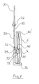
- a glass holder clamp 2 consists of a part of a central metal rod 20, forming the body pliers, bent at one end to form a hook 21 in U allowing it to be suspended from the bar 1 by snapping it in at its curved end 21 in a notch 10 and on the other hand gripping means and clamping 3 of the 40.40 'glass allowing it to be held on the clamp substantially parallel to the axis of the rod 20 by pinching its peripheral edge as can be seen see in figure 2.
- the space 22 created between the branches 23.24 of the U is intended to receive the bar 1 which is clamped between part of the branches 23.24 of which one 23 of these last is engaged in a notch 10 whose bottom 11 is also straight, the contact between the two faces rectilinear lines of one of the branches and of the bottom of the notch having the effect of preventing the rod central 20 to rotate freely around the bar 2 and fall, especially during transport of the support or during the evolution of the support in a chain of treatment.
- the glass holder clips 2 can thus be easily assembled or disassembled from bar 1 by simple snap hook 21 into the notches 10 and it is then possible to perform optical glass checks without touching it directly with your fingers, removing the corresponding clamp 2 of the chassis.
- the 3 means for gripping the optical glass are constituted by a thin metal rod 30 bent in its middle so as to form two lever arms 31,31 'and secured at its fold to the body 20 of the clamp 2 thanks to a rivet 32.
- the two lever arms 31, 31 ' are resiliently recalled towards each other which allows pinch the 4.4 'optical glass between the two ends 32.32 'free from the arms 31.41' via a contact piece 33.33 ', as can be seen on the figure 2.
- the contact piece 33.33 ' is a piece metal blade-shaped having at its end intended to be in contact with the optical glass 4,4 'a 34.34 'curved cutout for holding glasses 4.4 'optics with variable thicknesses.
- the 44.44 'curved cutouts reveal each two points respectively 35.35 'allowing to hold a very thick 4 'optical glass with the peripheral edge 40 of the glass 4 between the tips 35.35 'which has the effect, especially after a application of varnish or other liquid, not to alter the latter due to a reduced contact surface.
- Thin 4 'optical glass are maintained by placing their peripheral edge 40 'of the between the two points respectively 35.35 of each cut out 34.34 '.
- the pliers thus obtained make it possible to avoid significant consumption of liquid or varnish after soaking unlike current pliers. Furthermore the glass holder device according to the present invention allows easy disassembly of the clamps while retaining a fixed position of the clamps when suspended on the bar of the chassis even in the event of overturning where the clamps and the glasses remain in position without falling.
Landscapes
- Engineering & Computer Science (AREA)
- Health & Medical Sciences (AREA)
- Manufacturing & Machinery (AREA)
- Ophthalmology & Optometry (AREA)
- Mechanical Engineering (AREA)
- Grinding And Polishing Of Tertiary Curved Surfaces And Surfaces With Complex Shapes (AREA)
- Surface Treatment Of Glass (AREA)
- Joining Of Glass To Other Materials (AREA)
- Re-Forming, After-Treatment, Cutting And Transporting Of Glass Products (AREA)
- Eyeglasses (AREA)
Abstract
Description
- la figure 1 représente une vue en perspective partielle de l'axe du support du dispositif porte verre selon la présente invention.
- la figure 2 représente une vue de profil d'une pince porte verre portant un verre optique.
Claims (6)
- Dispositif porte verres destiné plus particulièrement au traitement des verres optiques (4,4') ou autres substrats, du type constitué d'un châssis comportant au moins une barre (1) horizontale de forme cylindrique supportant des pinces porte verre (2) caractérisé en ce qu'une pince porte verre (2) est constituée d'une part d'une tige centrale (20) formant le corps de la pince (2) et comportant à l'une de ses extrémités des moyens d'accrochage (21,22,25) permettant de solidariser de manière amovible lesdites pinces à ladite barre l'une derrière l'autre à des emplacements (10) espacés régulièrement et des moyens de verrouillage (23,24,25) empêchant la rotation libre de ladite pince (2) autour de la barre (1) et d'autre part de moyens de maintien (3) en position du verre sur ladite pince (2), ledit verre (4,4') étant maintenu sensiblement parallèlement à l'axe de la tige centrale (20).
- Dispositif porte verres selon la revendication 1 caractérisé en ce que la tige centrale (20) est recourbée à l'une de ses extrémités pour former un crochet permettant de suspendre la pince à la barre (1) en l'encliquetant par son crochet dans une encoche (10) pratiquée dans la barre (1).
- Dispositif porte verre selon la revendication 2 caractérisé en ce que le crochet (21) est recourbé en U de manière à créer un espace (22) délimité par les deux branches (23,24) du U et destiné à recevoir la barre (1) qui est enserrée par les deux branches (23,24) et dont l'une des branches est engagée dans une encoche (10) dont le fond (11) est rectiligne de manière à empêcher, par son contact avec ladite branche (23,24), la pince (2) de tourner librement autour de la barre (1).
- Dispositif porte verres selon l'une quelconque des revendications précédentes caractérisé en ce que les moyens de maintien (3) d'un verre optique sur une pince (2) sont constitués de deux bras de levier (41,41') montés autour d'un axe pivot (42) commun, solidarisé à la tige centrale (20), rappelés élastiquement l'un vers l'autre de manière à saisir et à serrer le verre entre leurs extrémités libres par pincement de son bord périphérique (40,40'), ledit verre reposant sur une butée (36) s'étendant perpendiculairement de la tige centrale de la pince.
- Dispositif porte verres selon la revendication 4 caractérisé en ce que les bras de leviers (41,41') sont munis à leur extrémité libre d'une pièce de contact (43,43') en forme de lame comportant à son bord destiné à être en contact avec le bord périphérique (40,40') du verre (4,4') une découpe (44,44') arrondie et incurvée délimité par deux pointes (45,45').
- Dispositif porte verres caractérisé en ce que les bras de leviers (41,41') sont réalisés en une seule pièce à partir d'une tige métallique pliée.
Priority Applications (5)
| Application Number | Priority Date | Filing Date | Title |
|---|---|---|---|
| EP02027942A EP1428585B1 (fr) | 2002-12-13 | 2002-12-13 | Dispositif porte verres destiné plus particulierement au traitement des verres optiques ou autres substrats |
| DE60211354T DE60211354T2 (de) | 2002-12-13 | 2002-12-13 | Vorrichtung zum Halten von optischen Gläsern, die besonders für die Behandlung von optischen Gläsern oder anderen Substraten geeignet ist |
| AT02027942T ATE325663T1 (de) | 2002-12-13 | 2002-12-13 | Vorrichtung zum halten von optischen gläsern, die besonders für die behandelung von optischen gläsern oder anderen substraten geeignet ist |
| JP2003334531A JP4452052B2 (ja) | 2002-12-13 | 2003-09-26 | 光学ガラス又は他の基板を処理するためのガラスホルダ装置 |
| US10/735,233 US7575210B2 (en) | 2002-12-13 | 2003-12-12 | Device for suspending lenses intended more particularly to optical lenses processing |
Applications Claiming Priority (1)
| Application Number | Priority Date | Filing Date | Title |
|---|---|---|---|
| EP02027942A EP1428585B1 (fr) | 2002-12-13 | 2002-12-13 | Dispositif porte verres destiné plus particulierement au traitement des verres optiques ou autres substrats |
Publications (2)
| Publication Number | Publication Date |
|---|---|
| EP1428585A1 true EP1428585A1 (fr) | 2004-06-16 |
| EP1428585B1 EP1428585B1 (fr) | 2006-05-10 |
Family
ID=32319598
Family Applications (1)
| Application Number | Title | Priority Date | Filing Date |
|---|---|---|---|
| EP02027942A Expired - Lifetime EP1428585B1 (fr) | 2002-12-13 | 2002-12-13 | Dispositif porte verres destiné plus particulierement au traitement des verres optiques ou autres substrats |
Country Status (5)
| Country | Link |
|---|---|
| US (1) | US7575210B2 (fr) |
| EP (1) | EP1428585B1 (fr) |
| JP (1) | JP4452052B2 (fr) |
| AT (1) | ATE325663T1 (fr) |
| DE (1) | DE60211354T2 (fr) |
Cited By (5)
| Publication number | Priority date | Publication date | Assignee | Title |
|---|---|---|---|---|
| EP1707278A1 (fr) * | 2005-04-01 | 2006-10-04 | Special Coating Laboratory International (S.C.L. International) | Dispositif de transport de verres optiques destiné à équiper une machine de nettoyage de verres optiques |
| WO2006111364A3 (fr) * | 2005-04-19 | 2007-04-12 | Special Coating Lab Internat | Unite de lavage pour une machine de nettoyage de verres ophtalmiques ou autres substrats |
| WO2012069756A1 (fr) * | 2010-11-25 | 2012-05-31 | Scl International Special Coating Laboratory | Dispositif porte-verre double |
| US8991805B2 (en) | 2010-11-25 | 2015-03-31 | Scl International Special Coating Laboratory | Lens-holder with offset hook |
| EP4596122A1 (fr) * | 2024-02-01 | 2025-08-06 | Mei S.R.L. | Machine et procédé de nettoyage de lentilles, telles que des lentilles de lunettes |
Families Citing this family (2)
| Publication number | Priority date | Publication date | Assignee | Title |
|---|---|---|---|---|
| ATE325663T1 (de) * | 2002-12-13 | 2006-06-15 | Special Coating Lab Internat S | Vorrichtung zum halten von optischen gläsern, die besonders für die behandelung von optischen gläsern oder anderen substraten geeignet ist |
| DE102005063312B4 (de) * | 2005-01-27 | 2007-08-23 | Carl Zeiss Vision Gmbh | Transportvorrichtung zum Handhaben von Linsen und Haltevorrichtung für diese |
Citations (5)
| Publication number | Priority date | Publication date | Assignee | Title |
|---|---|---|---|---|
| EP0215261A2 (fr) * | 1985-09-10 | 1987-03-25 | Balzers Aktiengesellschaft | Support de lentilles, en particulier pour nettoyage et dépôt subséquent de couches sur des lentilles ophtalmiques |
| DE9001964U1 (de) * | 1990-02-20 | 1990-04-26 | Schnoor, Olaf, 2000 Hamburg | Halteelement für optische Gläser, insbesondere Brillengläser |
| EP0483034A2 (fr) * | 1990-10-24 | 1992-04-29 | MACI OPTIC Sarl | Dispositif de maintien, notamment de verres d'optique |
| DE4418950A1 (de) * | 1994-05-31 | 1995-12-07 | Olaf Schnoor | Halteelement für optische Gläser, insbesondere Brillengläser |
| US5988191A (en) * | 1997-11-19 | 1999-11-23 | Coburn Optical Industries, Inc. | Holder for ophthalmic lenses and lens blocks |
Family Cites Families (8)
| Publication number | Priority date | Publication date | Assignee | Title |
|---|---|---|---|---|
| US2884219A (en) * | 1955-01-24 | 1959-04-28 | Anthony D Glover | Clip for holding spectacles or the like |
| EP0626816B1 (fr) * | 1992-11-26 | 1998-03-04 | JANOUSCHEK, Heinz | Support pour lunettes |
| US5372345A (en) * | 1993-06-16 | 1994-12-13 | Schmidt; Ray T. | Eyeglass holder |
| US5511705A (en) * | 1995-02-06 | 1996-04-30 | Dreszer; George C. | Interchangeable tool and fastener carrying and storage system |
| US5794312A (en) * | 1995-02-15 | 1998-08-18 | O'mahony; Sean Patrick | Holding device |
| US5864924A (en) * | 1997-01-15 | 1999-02-02 | Rodriguez; Luis | Eyeglass holder |
| US6330962B1 (en) * | 2000-10-30 | 2001-12-18 | Luis Rodriguez | Eyeglass holder |
| ATE325663T1 (de) * | 2002-12-13 | 2006-06-15 | Special Coating Lab Internat S | Vorrichtung zum halten von optischen gläsern, die besonders für die behandelung von optischen gläsern oder anderen substraten geeignet ist |
-
2002
- 2002-12-13 AT AT02027942T patent/ATE325663T1/de not_active IP Right Cessation
- 2002-12-13 DE DE60211354T patent/DE60211354T2/de not_active Expired - Lifetime
- 2002-12-13 EP EP02027942A patent/EP1428585B1/fr not_active Expired - Lifetime
-
2003
- 2003-09-26 JP JP2003334531A patent/JP4452052B2/ja not_active Expired - Lifetime
- 2003-12-12 US US10/735,233 patent/US7575210B2/en active Active
Patent Citations (5)
| Publication number | Priority date | Publication date | Assignee | Title |
|---|---|---|---|---|
| EP0215261A2 (fr) * | 1985-09-10 | 1987-03-25 | Balzers Aktiengesellschaft | Support de lentilles, en particulier pour nettoyage et dépôt subséquent de couches sur des lentilles ophtalmiques |
| DE9001964U1 (de) * | 1990-02-20 | 1990-04-26 | Schnoor, Olaf, 2000 Hamburg | Halteelement für optische Gläser, insbesondere Brillengläser |
| EP0483034A2 (fr) * | 1990-10-24 | 1992-04-29 | MACI OPTIC Sarl | Dispositif de maintien, notamment de verres d'optique |
| DE4418950A1 (de) * | 1994-05-31 | 1995-12-07 | Olaf Schnoor | Halteelement für optische Gläser, insbesondere Brillengläser |
| US5988191A (en) * | 1997-11-19 | 1999-11-23 | Coburn Optical Industries, Inc. | Holder for ophthalmic lenses and lens blocks |
Cited By (7)
| Publication number | Priority date | Publication date | Assignee | Title |
|---|---|---|---|---|
| EP1707278A1 (fr) * | 2005-04-01 | 2006-10-04 | Special Coating Laboratory International (S.C.L. International) | Dispositif de transport de verres optiques destiné à équiper une machine de nettoyage de verres optiques |
| WO2006111364A3 (fr) * | 2005-04-19 | 2007-04-12 | Special Coating Lab Internat | Unite de lavage pour une machine de nettoyage de verres ophtalmiques ou autres substrats |
| WO2012069756A1 (fr) * | 2010-11-25 | 2012-05-31 | Scl International Special Coating Laboratory | Dispositif porte-verre double |
| FR2967986A1 (fr) * | 2010-11-25 | 2012-06-01 | Scl Internat Special Coating Lab | Dispositif porte-verre double |
| US8991805B2 (en) | 2010-11-25 | 2015-03-31 | Scl International Special Coating Laboratory | Lens-holder with offset hook |
| US9448381B2 (en) | 2010-11-25 | 2016-09-20 | Scl International Special Coating Laboratory | Dual lens-holding device |
| EP4596122A1 (fr) * | 2024-02-01 | 2025-08-06 | Mei S.R.L. | Machine et procédé de nettoyage de lentilles, telles que des lentilles de lunettes |
Also Published As
| Publication number | Publication date |
|---|---|
| EP1428585B1 (fr) | 2006-05-10 |
| DE60211354T2 (de) | 2007-03-29 |
| ATE325663T1 (de) | 2006-06-15 |
| JP4452052B2 (ja) | 2010-04-21 |
| DE60211354D1 (de) | 2006-06-14 |
| US20080029466A1 (en) | 2008-02-07 |
| US7575210B2 (en) | 2009-08-18 |
| JP2004196648A (ja) | 2004-07-15 |
Similar Documents
| Publication | Publication Date | Title |
|---|---|---|
| EP0043883A2 (fr) | Crochet de lien, notamment crochet de lien élastique | |
| EP2643097B1 (fr) | Dispositif porte-verre double | |
| FR2932273A1 (fr) | Pince adaptee pour saisir un support d'echantillons biologiques, ensemble d'un support echantillons biologiques et d'une pince adaptee pour le saisir, et automate de traitement et/ou d'analyse d'echantillons biologiques | |
| EP0816202A1 (fr) | Dispositif de porte-outil destiné à être adapté sur une brouette | |
| EP1428585B1 (fr) | Dispositif porte verres destiné plus particulierement au traitement des verres optiques ou autres substrats | |
| FR2967987A1 (fr) | Porte-verre avec hampe deportee | |
| FR2490989A1 (fr) | Pince de prehension d'objets et tete preneuse equipee de telles pinces | |
| FR2641500A1 (fr) | Appareil pour maintenir un objet, par exemple un oeuf en vue de le peindre | |
| EP0209420A1 (fr) | Dispositif tel que sous-verre pour présenter un document | |
| FR2946104A1 (fr) | Dispositif de pince a ecrou, susceptible d'etre place sur le bord d'un support tel qu'un panneau | |
| FR2771908A1 (fr) | Support de document | |
| FR2668578A1 (fr) | Dispositif de maintien, notamment de verres d'optique. | |
| EP0639405B1 (fr) | Dispositif de support et de protection d'un élément tubulaire de très faible diamètre, notamment du genre micropipette | |
| EP1972495A2 (fr) | Poignée destinée à la manutention d'un boîtier d'un moyen d'éclairage/signalisation pour véhicule automobile et procédé de manutention d'un tel boîtier | |
| FR2658945A1 (fr) | Dispositif porte-detecteur et detecteur de proximite inductif equipe de ce dispositif. | |
| FR3109548A1 (fr) | Dispositif pour le prélèvement d’un objet à sensibilité magnétique | |
| FR2625360A1 (fr) | Support pour une pancarte de signalisation ou similaire devant etre apposee sur un element constitue par une grille metallique | |
| EP1470984B1 (fr) | Dispositif destiné à faciliter la manipulation d'un bac à deux roues de collecte de déchets | |
| WO2008110701A2 (fr) | Dispositif de maintien d'une cravate ou d'un article d'habillement similaire | |
| FR3105768A1 (fr) | Système d'essuyage pour véhicule automobile | |
| FR2501981A1 (fr) | Poignee porte-sacs | |
| EP0579562B1 (fr) | Outil de préhension de nacelles pour plaquettes de silicium | |
| FR2949768A1 (fr) | Convoyeur a pinces | |
| FR2913368A1 (fr) | Dispositif pour immobiliser un porte brosse sur un pot de peinture | |
| EP1375408A1 (fr) | Dispositif comportant une membrane élastique pour la préhension et la manipulation d'objets fragiles et lourds en milieu industriel |
Legal Events
| Date | Code | Title | Description |
|---|---|---|---|
| PUAI | Public reference made under article 153(3) epc to a published international application that has entered the european phase |
Free format text: ORIGINAL CODE: 0009012 |
|
| AK | Designated contracting states |
Kind code of ref document: A1 Designated state(s): AT BE BG CH CY CZ DE DK EE ES FI FR GB GR IE IT LI LU MC NL PT SE SI SK TR |
|
| AX | Request for extension of the european patent |
Extension state: AL LT LV MK RO |
|
| 17P | Request for examination filed |
Effective date: 20041015 |
|
| AKX | Designation fees paid |
Designated state(s): AT BE BG CH CY CZ DE DK EE ES FI FR GB GR IE IT LI LU MC NL PT SE SI SK TR |
|
| 17Q | First examination report despatched |
Effective date: 20050204 |
|
| GRAP | Despatch of communication of intention to grant a patent |
Free format text: ORIGINAL CODE: EPIDOSNIGR1 |
|
| GRAS | Grant fee paid |
Free format text: ORIGINAL CODE: EPIDOSNIGR3 |
|
| GRAA | (expected) grant |
Free format text: ORIGINAL CODE: 0009210 |
|
| AK | Designated contracting states |
Kind code of ref document: B1 Designated state(s): AT BE BG CH CY CZ DE DK EE ES FI FR GB GR IE IT LI LU MC NL PT SE SI SK TR |
|
| PG25 | Lapsed in a contracting state [announced via postgrant information from national office to epo] |
Ref country code: SK Free format text: LAPSE BECAUSE OF FAILURE TO SUBMIT A TRANSLATION OF THE DESCRIPTION OR TO PAY THE FEE WITHIN THE PRESCRIBED TIME-LIMIT Effective date: 20060510 Ref country code: SI Free format text: LAPSE BECAUSE OF FAILURE TO SUBMIT A TRANSLATION OF THE DESCRIPTION OR TO PAY THE FEE WITHIN THE PRESCRIBED TIME-LIMIT Effective date: 20060510 Ref country code: NL Free format text: LAPSE BECAUSE OF FAILURE TO SUBMIT A TRANSLATION OF THE DESCRIPTION OR TO PAY THE FEE WITHIN THE PRESCRIBED TIME-LIMIT Effective date: 20060510 Ref country code: IE Free format text: LAPSE BECAUSE OF FAILURE TO SUBMIT A TRANSLATION OF THE DESCRIPTION OR TO PAY THE FEE WITHIN THE PRESCRIBED TIME-LIMIT Effective date: 20060510 Ref country code: FI Free format text: LAPSE BECAUSE OF FAILURE TO SUBMIT A TRANSLATION OF THE DESCRIPTION OR TO PAY THE FEE WITHIN THE PRESCRIBED TIME-LIMIT Effective date: 20060510 Ref country code: CZ Free format text: LAPSE BECAUSE OF FAILURE TO SUBMIT A TRANSLATION OF THE DESCRIPTION OR TO PAY THE FEE WITHIN THE PRESCRIBED TIME-LIMIT Effective date: 20060510 Ref country code: AT Free format text: LAPSE BECAUSE OF FAILURE TO SUBMIT A TRANSLATION OF THE DESCRIPTION OR TO PAY THE FEE WITHIN THE PRESCRIBED TIME-LIMIT Effective date: 20060510 |
|
| REG | Reference to a national code |
Ref country code: GB Ref legal event code: FG4D Free format text: NOT ENGLISH |
|
| REG | Reference to a national code |
Ref country code: CH Ref legal event code: EP |
|
| REF | Corresponds to: |
Ref document number: 60211354 Country of ref document: DE Date of ref document: 20060614 Kind code of ref document: P |
|
| REG | Reference to a national code |
Ref country code: IE Ref legal event code: FG4D Free format text: LANGUAGE OF EP DOCUMENT: FRENCH |
|
| PG25 | Lapsed in a contracting state [announced via postgrant information from national office to epo] |
Ref country code: SE Free format text: LAPSE BECAUSE OF FAILURE TO SUBMIT A TRANSLATION OF THE DESCRIPTION OR TO PAY THE FEE WITHIN THE PRESCRIBED TIME-LIMIT Effective date: 20060810 Ref country code: DK Free format text: LAPSE BECAUSE OF FAILURE TO SUBMIT A TRANSLATION OF THE DESCRIPTION OR TO PAY THE FEE WITHIN THE PRESCRIBED TIME-LIMIT Effective date: 20060810 |
|
| PG25 | Lapsed in a contracting state [announced via postgrant information from national office to epo] |
Ref country code: ES Free format text: LAPSE BECAUSE OF FAILURE TO SUBMIT A TRANSLATION OF THE DESCRIPTION OR TO PAY THE FEE WITHIN THE PRESCRIBED TIME-LIMIT Effective date: 20060821 |
|
| REG | Reference to a national code |
Ref country code: CH Ref legal event code: NV Representative=s name: BOVARD AG PATENTANWAELTE |
|
| GBT | Gb: translation of ep patent filed (gb section 77(6)(a)/1977) |
Effective date: 20060815 |
|
| PG25 | Lapsed in a contracting state [announced via postgrant information from national office to epo] |
Ref country code: PT Free format text: LAPSE BECAUSE OF FAILURE TO SUBMIT A TRANSLATION OF THE DESCRIPTION OR TO PAY THE FEE WITHIN THE PRESCRIBED TIME-LIMIT Effective date: 20061010 |
|
| NLV1 | Nl: lapsed or annulled due to failure to fulfill the requirements of art. 29p and 29m of the patents act | ||
| REG | Reference to a national code |
Ref country code: IE Ref legal event code: FD4D |
|
| PG25 | Lapsed in a contracting state [announced via postgrant information from national office to epo] |
Ref country code: MC Free format text: LAPSE BECAUSE OF NON-PAYMENT OF DUE FEES Effective date: 20061231 |
|
| PGFP | Annual fee paid to national office [announced via postgrant information from national office to epo] |
Ref country code: IT Payment date: 20061231 Year of fee payment: 5 |
|
| PGFP | Annual fee paid to national office [announced via postgrant information from national office to epo] |
Ref country code: GB Payment date: 20070109 Year of fee payment: 5 |
|
| PLBE | No opposition filed within time limit |
Free format text: ORIGINAL CODE: 0009261 |
|
| STAA | Information on the status of an ep patent application or granted ep patent |
Free format text: STATUS: NO OPPOSITION FILED WITHIN TIME LIMIT |
|
| 26N | No opposition filed |
Effective date: 20070213 |
|
| PG25 | Lapsed in a contracting state [announced via postgrant information from national office to epo] |
Ref country code: GR Free format text: LAPSE BECAUSE OF FAILURE TO SUBMIT A TRANSLATION OF THE DESCRIPTION OR TO PAY THE FEE WITHIN THE PRESCRIBED TIME-LIMIT Effective date: 20060811 |
|
| PG25 | Lapsed in a contracting state [announced via postgrant information from national office to epo] |
Ref country code: BG Free format text: LAPSE BECAUSE OF FAILURE TO SUBMIT A TRANSLATION OF THE DESCRIPTION OR TO PAY THE FEE WITHIN THE PRESCRIBED TIME-LIMIT Effective date: 20060810 Ref country code: EE Free format text: LAPSE BECAUSE OF FAILURE TO SUBMIT A TRANSLATION OF THE DESCRIPTION OR TO PAY THE FEE WITHIN THE PRESCRIBED TIME-LIMIT Effective date: 20060510 |
|
| PG25 | Lapsed in a contracting state [announced via postgrant information from national office to epo] |
Ref country code: TR Free format text: LAPSE BECAUSE OF FAILURE TO SUBMIT A TRANSLATION OF THE DESCRIPTION OR TO PAY THE FEE WITHIN THE PRESCRIBED TIME-LIMIT Effective date: 20060510 Ref country code: LU Free format text: LAPSE BECAUSE OF NON-PAYMENT OF DUE FEES Effective date: 20061213 |
|
| PGFP | Annual fee paid to national office [announced via postgrant information from national office to epo] |
Ref country code: FR Payment date: 20071231 Year of fee payment: 6 |
|
| GBPC | Gb: european patent ceased through non-payment of renewal fee |
Effective date: 20071213 |
|
| REG | Reference to a national code |
Ref country code: FR Ref legal event code: ST Effective date: 20081020 |
|
| PG25 | Lapsed in a contracting state [announced via postgrant information from national office to epo] |
Ref country code: CY Free format text: LAPSE BECAUSE OF FAILURE TO SUBMIT A TRANSLATION OF THE DESCRIPTION OR TO PAY THE FEE WITHIN THE PRESCRIBED TIME-LIMIT Effective date: 20060510 |
|
| PG25 | Lapsed in a contracting state [announced via postgrant information from national office to epo] |
Ref country code: GB Free format text: LAPSE BECAUSE OF NON-PAYMENT OF DUE FEES Effective date: 20071213 |
|
| PG25 | Lapsed in a contracting state [announced via postgrant information from national office to epo] |
Ref country code: FR Free format text: LAPSE BECAUSE OF NON-PAYMENT OF DUE FEES Effective date: 20071231 |
|
| PG25 | Lapsed in a contracting state [announced via postgrant information from national office to epo] |
Ref country code: IT Free format text: LAPSE BECAUSE OF NON-PAYMENT OF DUE FEES Effective date: 20071213 |
|
| REG | Reference to a national code |
Ref country code: CH Ref legal event code: PFA Owner name: SPECIAL COATING LABORATORY INTERNATIONAL (S.C.L. Free format text: SPECIAL COATING LABORATORY INTERNATIONAL (S.C.L. INTERNATIONAL) S.A.R.L.#BUSINESS PARK-SITE D'ARCHAMPS#74160 ARCHAMPS (FR) -TRANSFER TO- SPECIAL COATING LABORATORY INTERNATIONAL (S.C.L. INTERNATIONAL) S.A.R.L.#BUSINESS PARK-SITE D'ARCHAMPS#74160 ARCHAMPS (FR) |
|
| PGFP | Annual fee paid to national office [announced via postgrant information from national office to epo] |
Ref country code: BE Payment date: 20191218 Year of fee payment: 18 |
|
| PGFP | Annual fee paid to national office [announced via postgrant information from national office to epo] |
Ref country code: CH Payment date: 20191115 Year of fee payment: 18 |
|
| REG | Reference to a national code |
Ref country code: CH Ref legal event code: PL |
|
| REG | Reference to a national code |
Ref country code: BE Ref legal event code: MM Effective date: 20201231 |
|
| PG25 | Lapsed in a contracting state [announced via postgrant information from national office to epo] |
Ref country code: LI Free format text: LAPSE BECAUSE OF NON-PAYMENT OF DUE FEES Effective date: 20201231 Ref country code: CH Free format text: LAPSE BECAUSE OF NON-PAYMENT OF DUE FEES Effective date: 20201231 |
|
| PGFP | Annual fee paid to national office [announced via postgrant information from national office to epo] |
Ref country code: DE Payment date: 20211117 Year of fee payment: 20 |
|
| PG25 | Lapsed in a contracting state [announced via postgrant information from national office to epo] |
Ref country code: BE Free format text: LAPSE BECAUSE OF NON-PAYMENT OF DUE FEES Effective date: 20201231 |
|
| REG | Reference to a national code |
Ref country code: DE Ref legal event code: R071 Ref document number: 60211354 Country of ref document: DE |