EP1428577A1 - Metal catalyst carrier - Google Patents
Metal catalyst carrier Download PDFInfo
- Publication number
- EP1428577A1 EP1428577A1 EP03293072A EP03293072A EP1428577A1 EP 1428577 A1 EP1428577 A1 EP 1428577A1 EP 03293072 A EP03293072 A EP 03293072A EP 03293072 A EP03293072 A EP 03293072A EP 1428577 A1 EP1428577 A1 EP 1428577A1
- Authority
- EP
- European Patent Office
- Prior art keywords
- sheet
- slots
- interval
- cell passage
- passage direction
- Prior art date
- Legal status (The legal status is an assumption and is not a legal conclusion. Google has not performed a legal analysis and makes no representation as to the accuracy of the status listed.)
- Granted
Links
Images


Classifications
-
- F—MECHANICAL ENGINEERING; LIGHTING; HEATING; WEAPONS; BLASTING
- F01—MACHINES OR ENGINES IN GENERAL; ENGINE PLANTS IN GENERAL; STEAM ENGINES
- F01N—GAS-FLOW SILENCERS OR EXHAUST APPARATUS FOR MACHINES OR ENGINES IN GENERAL; GAS-FLOW SILENCERS OR EXHAUST APPARATUS FOR INTERNAL-COMBUSTION ENGINES
- F01N3/00—Exhaust or silencing apparatus having means for purifying, rendering innocuous, or otherwise treating exhaust
- F01N3/08—Exhaust or silencing apparatus having means for purifying, rendering innocuous, or otherwise treating exhaust for rendering innocuous
- F01N3/10—Exhaust or silencing apparatus having means for purifying, rendering innocuous, or otherwise treating exhaust for rendering innocuous by thermal or catalytic conversion of noxious components of exhaust
- F01N3/24—Exhaust or silencing apparatus having means for purifying, rendering innocuous, or otherwise treating exhaust for rendering innocuous by thermal or catalytic conversion of noxious components of exhaust characterised by constructional aspects of converting apparatus
- F01N3/28—Construction of catalytic reactors
- F01N3/2803—Construction of catalytic reactors characterised by structure, by material or by manufacturing of catalyst support
- F01N3/2807—Metal other than sintered metal
- F01N3/281—Metallic honeycomb monoliths made of stacked or rolled sheets, foils or plates
- F01N3/2821—Metallic honeycomb monoliths made of stacked or rolled sheets, foils or plates the support being provided with means to enhance the mixing process inside the converter, e.g. sheets, plates or foils with protrusions or projections to create turbulence
-
- B—PERFORMING OPERATIONS; TRANSPORTING
- B01—PHYSICAL OR CHEMICAL PROCESSES OR APPARATUS IN GENERAL
- B01J—CHEMICAL OR PHYSICAL PROCESSES, e.g. CATALYSIS OR COLLOID CHEMISTRY; THEIR RELEVANT APPARATUS
- B01J35/00—Catalysts, in general, characterised by their form or physical properties
- B01J35/50—Catalysts, in general, characterised by their form or physical properties characterised by their shape or configuration
- B01J35/56—Foraminous structures having flow-through passages or channels, e.g. grids or three-dimensional [3D] monoliths
- B01J35/57—Honeycombs
-
- F—MECHANICAL ENGINEERING; LIGHTING; HEATING; WEAPONS; BLASTING
- F01—MACHINES OR ENGINES IN GENERAL; ENGINE PLANTS IN GENERAL; STEAM ENGINES
- F01N—GAS-FLOW SILENCERS OR EXHAUST APPARATUS FOR MACHINES OR ENGINES IN GENERAL; GAS-FLOW SILENCERS OR EXHAUST APPARATUS FOR INTERNAL-COMBUSTION ENGINES
- F01N2330/00—Structure of catalyst support or particle filter
- F01N2330/02—Metallic plates or honeycombs, e.g. superposed or rolled-up corrugated or otherwise deformed sheet metal
- F01N2330/04—Methods of manufacturing
-
- F—MECHANICAL ENGINEERING; LIGHTING; HEATING; WEAPONS; BLASTING
- F01—MACHINES OR ENGINES IN GENERAL; ENGINE PLANTS IN GENERAL; STEAM ENGINES
- F01N—GAS-FLOW SILENCERS OR EXHAUST APPARATUS FOR MACHINES OR ENGINES IN GENERAL; GAS-FLOW SILENCERS OR EXHAUST APPARATUS FOR INTERNAL-COMBUSTION ENGINES
- F01N2330/00—Structure of catalyst support or particle filter
- F01N2330/30—Honeycomb supports characterised by their structural details
- F01N2330/38—Honeycomb supports characterised by their structural details flow channels with means to enhance flow mixing,(e.g. protrusions or projections)
-
- Y—GENERAL TAGGING OF NEW TECHNOLOGICAL DEVELOPMENTS; GENERAL TAGGING OF CROSS-SECTIONAL TECHNOLOGIES SPANNING OVER SEVERAL SECTIONS OF THE IPC; TECHNICAL SUBJECTS COVERED BY FORMER USPC CROSS-REFERENCE ART COLLECTIONS [XRACs] AND DIGESTS
- Y10—TECHNICAL SUBJECTS COVERED BY FORMER USPC
- Y10T—TECHNICAL SUBJECTS COVERED BY FORMER US CLASSIFICATION
- Y10T428/00—Stock material or miscellaneous articles
- Y10T428/12—All metal or with adjacent metals
- Y10T428/1234—Honeycomb, or with grain orientation or elongated elements in defined angular relationship in respective components [e.g., parallel, inter- secting, etc.]
-
- Y—GENERAL TAGGING OF NEW TECHNOLOGICAL DEVELOPMENTS; GENERAL TAGGING OF CROSS-SECTIONAL TECHNOLOGIES SPANNING OVER SEVERAL SECTIONS OF THE IPC; TECHNICAL SUBJECTS COVERED BY FORMER USPC CROSS-REFERENCE ART COLLECTIONS [XRACs] AND DIGESTS
- Y10—TECHNICAL SUBJECTS COVERED BY FORMER USPC
- Y10T—TECHNICAL SUBJECTS COVERED BY FORMER US CLASSIFICATION
- Y10T428/00—Stock material or miscellaneous articles
- Y10T428/12—All metal or with adjacent metals
- Y10T428/12361—All metal or with adjacent metals having aperture or cut
-
- Y—GENERAL TAGGING OF NEW TECHNOLOGICAL DEVELOPMENTS; GENERAL TAGGING OF CROSS-SECTIONAL TECHNOLOGIES SPANNING OVER SEVERAL SECTIONS OF THE IPC; TECHNICAL SUBJECTS COVERED BY FORMER USPC CROSS-REFERENCE ART COLLECTIONS [XRACs] AND DIGESTS
- Y10—TECHNICAL SUBJECTS COVERED BY FORMER USPC
- Y10T—TECHNICAL SUBJECTS COVERED BY FORMER US CLASSIFICATION
- Y10T428/00—Stock material or miscellaneous articles
- Y10T428/12—All metal or with adjacent metals
- Y10T428/1241—Nonplanar uniform thickness or nonlinear uniform diameter [e.g., L-shape]
Definitions
- the present invention relates to a metal catalyst carrier that is installed in an exhaust system of an internal combustion engine and the like to purify exhaust gas.
- a conventional metal catalyst carrier is disclosed in Japanese patent laid-open Tokkai 2002-143693.
- This metal catalyst carrier is produced by several manufacturing processes including a preparing process of preparing sheet metals for a corrugated sheet and a flat sheet, a slot forming process of forming the sheet metal for at least the corrugated sheet out of the corrugated sheet and the flat sheet with a plurality of slots, a corrugating process of corrugating one of the metal sheet formed with the slots, a rolling process of stacking the corrugated sheet and the flat sheet and rolling them in multi-layers to obtain a cylindrical core, and a press-fitting process of press-fitting the core into an outer cylinder.
- the core therefore, is provided with a plurality of cell passages, formed between the corrugated sheet and the flat sheet, through which exhaust gas from an engine passes to the atmosphere.
- the slots through which the exhaust gas passes from one to another of the cell passages, constitutes a plurality of slot arrays each of which has the plural slots and is set in a cell passage direction.
- the slot arrays are arranged to have a predetermined interval equal to zero or larger than zero in a direction perpendicular to the cell passage direction between opening peripheral edge portions of the slots adjacent to each other in the slot arrays adjacent to each other so as not to overlap each other.
- the above-predetermined interval is set to prevent the sheet metal with the slots from being distorted or cracked during the corrugating process.
- a metal catalyst carrier of the present invention includes: a highly corrugated sheet made of a sheet metal; and one of a slightly corrugated sheet and a flat sheet made of a sheet metal, the slightly corrugated sheet having a smaller corrugation than a corrugation of the highly corrugated sheet, wherein the highly corrugated sheet and the one of the slightly corrugated sheet and the flat sheet are stacked and rolled in multi-layers so as to form cell passages through which exhaust gas passes between the highly corrugated sheet and the one of the slightly corrugated sheet and the flat sheet, the highly corrugated sheet being provided with a plurality of slot arrays arranged in a cell passage direction respectively, the slot arrays having a plurality of slots formed before the sheet metal is corrugated and arranged in a direction perpendicular to the cell passage direction respectively, and wherein an interval X is set in the direction perpendicular to the cell passage direction between opening peripheral edge portions of the slots adjacent to each other in the slot arrays adjacent to
- the metal catalyst carrier of the present invention prevents the occurrence of distortions and cracks in the process of corrugating the sheet metal when the interval Y in the cell passage direction and the interval X in the direction perpendicular to the cell passage direction, between the opening peripheral edge portions of the slots adjacent to each other in the slot arrays adjacent to each other, are set under the above-described conditions.
- the occurrence of the distortions and cracks in the process of corrugating the sheet metal is prevented by such setting that the interval Y in the cell passage direction is 4 mm or more when the interval X in the direction perpendicular to the direction of the cell passage is zero as the condition of the minimum interval X.
- the interval X in the direction perpendicular to the cell passage direction can be set narrower by a 5/2 ratio of an increased amount of the interval Y, and when the interval Y is 4 mm, the interval X can be set to zero as the condition of the minimum interval X.
- the highly corrugated sheet is 20 ⁇ m to 50 ⁇ m in sheet thickness.
- a length L of each of the slots in the direction perpendicular to the cell passage direction is set under a condition of L ⁇ 15 mm.
- the interval Y in the cell passage direction between the opening peripheral edge portions of the slots adjacent to each other in the slot arrays adjacent to each other and a pitch P of the slots in each of the slot arrays are set under a condition of Y ⁇ -(1/2)P + 14.5 mm.
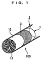
- FIG. 1 is a perspective view partly in section showing a metal catalyst carrier 100 of the embodiment according to the invention
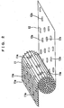
- FIG. 2 is a perspective view showing a corrugated sheet 11 and a flat sheet 12 in a process of stacking and rolling them.
- the metal catalyst carrier 100 has a core 1, an outer cylinder 2 in which the core 1 is press-fitted, and a brazing foil material 3 interposed between the core 1 and the outer cylinder 2.
- the outer cylinder 2 is made of SUS430 ferritic stainless sheet material with a sheet thickness of 1 mm to 2 mm, and formed in a cylindrical shape with an inside diameter smaller than an outside diameter of the core 1 before the core 1 is press-fitted in the outer cylinder 2.
- the brazing foil material 3 is wound around the outer peripheral surface of the core 1 before the core 1 is press-fitted in the outer cylinder 2.
- this brazing foil material 3 covers a part of the outer peripheral surface of the core 1 at its middle portion deviated from the center of the core 1 toward an exhaust gas outlet side end portion (right end portion in FIG. 1) of the core 1.
- the core 1 is constructed so that the corrugated sheet 11 and the flat sheet 12, both made of a sheet metal with a sheet thickness of 30 ⁇ m, are stacked each other and rolled in multi-layers with the flat sheet 12 being on the outer side of the core 1, which forms a honeycomb structure.
- the honeycomb structure is disposed in an exhaust gas passage from an internal combustion engine, not shown, to reduce HC, CO, NOx, and so on in exhaust gas. It has a plurality of honeycomb passages (cell passages), defined by walls of the corrugated sheet 11 and the flat sheet 12, with a catalyst carrier layer, formed on the surfaces of the walls, which is made of alumina or the like and carries noble metal for purifying exhaust gas passing through the cell passages.
- the corrugated sheet 11 functions as a highly corrugated sheet of the present invention.
- the corrugated sheet 11 is obtained by corrugating a flat sheet metal formed with a plurality of slots 11a. As shown in FIGS. 2 and 3, the slots 11a are formed before corrugating the flat sheet metal to have a predetermined length L and disposed so as to be a predetermined intervals X and Y between the slots which are adjacent to each other in a cell passage direction and in a direction perpendicular to the cell passage direction respectively, which will be described in detail later.
- the flat sheet 12 is also formed with a plurality of slots 12a having a predetermined length that are disposed so as to have predetermined intervals between the slots adjacent to each another in the same directions as the corrugated sheet 11 respectively.
- the metal catalyst carrier 100 in order to improve an exhaust gas purifying performance, it is effective to actively cause turbulent motion of the exhaust gas when passing through the cell passages to contact the exhaust gas to the noble metal as much as possible.
- a large number of the slots 11a and 12a in a shape elongated in the direction perpendicular to the cell passages are formed in the corrugated sheet 11 and the flat sheet 12 respectively.
- the exhaust gas is allowed to pass from one to another of the cell passages, separated by the wall of the corrugated sheet 11 and the flat sheet 12, through these slots 11a and 12a so that the flow of the exhaust gas inside the core 1 is further promoted to be turbulent in a width direction (direction perpendicular to the cell passage direction), thereby improving the exhaust gas purifying performance.
- FIG. 3 shows a layout pattern where a plurality of slot arrays, each constituted of the plural slots 11a disposed along the direction perpendicular to the cell passage direction 13, are arranged in the cell passage direction 13, and sheet metals in which layout patterns were variously set by varying the interval Y, the interval X, the length L, and a pitch P are prepared, the interval Y being an interval in the cell passage direction 13 between opening peripheral edge portions of the slots 11a adjacent to each other in the slot arrays adjacent to each other, the interval X being an interval in the direction perpendicular to the cell passage direction 13 between the opening peripheral edge portions of the slots 11a adjacent to each other in the slot arrays adjacent to each other, the length L being a length of each of the slots 11 a in the direction perpendicular to the cell passage direction 13, and the pitch P being a pitch of the slots 11a adjacent to each other in each of the slot arrays.
- FIG. 4 to FIG. 6 are data showing the results of the above-described experiment.
- FIG. 4 shows the correlation between the interval X and the interval Y
- FIG. 5 shows the correlation between the interval X and the length L
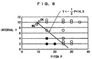
- FIG. 6 shows the correlation between the interval Y and the pitch P. Note that marks "OK” and "NG” in these data indicate ranges where no distortion or crack occurred and ranges where the occurrence of distortions or cracks was observed, respectively.
- this results means that when the interval Y is set to 4 mm or more with the interval X being set to zero, as a condition where the interval X is the minimum, the occurrence of the distortions or the cracks in the corrugated sheet is prevented.
- the interval X can be set narrower by a 5/2 ratio of an increased amount of the interval Y without the occurrence of the distortions or the cracks.
- the interval X can be set to zero, which is the condition where the interval X is the minimum.
- the pitch P under the setting of the pitch P to 29 mm or more, the occurrence of the distortions and cracks in the corrugating sheet is prevented even when the interval Y is set to zero.
- the pitch P As the pitch P is more reduced from 29 mm, it is necessary to widen the interval Y by a 1/2 ratio of a reduced amount of the pitch P.
- the metal catalyst carrier of this embodiment of the invention when the intervals X and Y, the length L, and the pitch P are set so as to fall within the ranges indicated by "OK" in the data of FIG. 4 to FIG. 6, the occurrence of the distortions and cracks in the corrugated sheet metal is prevented and thereby leading to better productivity.
- the experiment was conducted using the sheet metals with a sheet thickness of 30 ⁇ m as the material of the corrugated sheet 11, but substantially the same result was observed in experiments using sheet metals with a sheet thickness of 20 ⁇ m to 50 ⁇ m, which may be adapted to the present invention.
- each slot is formed in a shape of a longitudinal slot, but the same effects are obtained with slots in other shapes, for example, a circular slot shape, which may be adapted to the present invention.
- the flat sheet 12 is used, but the same effects are obtainable when a slightly corrugated sheet having a smaller corrugation than that of the corrugated sheet 11 is used in place of the flat sheet 12, which may be adapted to the present invention.
Landscapes
- Chemical & Material Sciences (AREA)
- Chemical Kinetics & Catalysis (AREA)
- Engineering & Computer Science (AREA)
- Health & Medical Sciences (AREA)
- Toxicology (AREA)
- Combustion & Propulsion (AREA)
- Mechanical Engineering (AREA)
- General Engineering & Computer Science (AREA)
- Catalysts (AREA)
- Exhaust Gas After Treatment (AREA)
- Exhaust Gas Treatment By Means Of Catalyst (AREA)
Abstract
Description
Referring to FIG. 1, the
The honeycomb structure is disposed in an exhaust gas passage from an internal combustion engine, not shown, to reduce HC, CO, NOx, and so on in exhaust gas. It has a plurality of honeycomb passages (cell passages), defined by walls of the corrugated sheet 11 and the
The
Claims (4)
- A metal catalyst carrier (100) comprising a highly corrugated sheet (11) made of a sheet metal and one of a slightly corrugated sheet and a flat sheet (12) made of a sheet metal, said slightly corrugated sheet having a smaller corrugation than a corrugation of said highly corrugated sheet (11), wherein said highly corrugated sheet (11) and the one of said slightly corrugated sheet and said flat sheet (12) are stacked and rolled in multi-layers so as to form cell passages through which exhaust gas passes between said highly corrugated sheet (11) and the one of said slightly corrugated sheet and said flat sheet (12), said highly corrugated sheet (11) being provided with a plurality of slot arrays arranged in a cell passage direction (13) respectively, the slot arrays having a plurality of slots (11a) which are formed before the sheet metal is corrugated and disposed along a direction perpendicular to the cell passage direction (13) respectively, and wherein an interval X is set in the direction perpendicular to the cell passage direction (13) between opening peripheral edge portions of the slots (11a) adjacent to each other in the slot arrays adjacent to each other, an interval Y being set in the cell passage direction (13) between the opening peripheral edge portions of the slots (11a) adjacent to each other in the slot arrays adjacent to each other, the interval X and the interval Y being set under a condition satisfying X ≥ 0 mm and X ≥ -(5/2)Y + 10 mm.
- A metal catalyst carrier (100) according to claim 1, wherein said highly corrugated sheet (11) is 20 µm to 50 µm in sheet thickness.
- A metal catalyst carrier (100) according to claim 1 or claim 2, wherein a length L of each of the slots (11a) in the direction perpendicular to the cell passage direction (13) is set under a condition of L ≤ 15 mm.
- A metal catalyst carrier (100) according to any one of claims 1 to 3, wherein the interval Y in the cell passage direction (13) between the opening peripheral edge portions of the slots (11a) adjacent to each other in the slot arrays adjacent to each other and a pitch P of the slots (11) in each of the slot arrays are set under a condition of Y ≥ -(1/2)P + 14.5 mm.
Applications Claiming Priority (2)
| Application Number | Priority Date | Filing Date | Title |
|---|---|---|---|
| JP2002359900 | 2002-12-11 | ||
| JP2002359900A JP4226884B2 (en) | 2002-12-11 | 2002-12-11 | Metal catalyst carrier |
Publications (2)
| Publication Number | Publication Date |
|---|---|
| EP1428577A1 true EP1428577A1 (en) | 2004-06-16 |
| EP1428577B1 EP1428577B1 (en) | 2005-06-08 |
Family
ID=32322111
Family Applications (1)
| Application Number | Title | Priority Date | Filing Date |
|---|---|---|---|
| EP03293072A Expired - Lifetime EP1428577B1 (en) | 2002-12-11 | 2003-12-09 | Metal catalyst carrier |
Country Status (4)
| Country | Link |
|---|---|
| US (1) | US7030059B2 (en) |
| EP (1) | EP1428577B1 (en) |
| JP (1) | JP4226884B2 (en) |
| DE (1) | DE60300811T2 (en) |
Cited By (1)
| Publication number | Priority date | Publication date | Assignee | Title |
|---|---|---|---|---|
| RU2391136C2 (en) * | 2005-02-18 | 2010-06-10 | Эмитек Гезельшафт Фюр Эмиссионстехнологи Мбх | Honeycomb element with inner cavities |
Families Citing this family (14)
| Publication number | Priority date | Publication date | Assignee | Title |
|---|---|---|---|---|
| JP2006150194A (en) * | 2004-11-26 | 2006-06-15 | Calsonic Kansei Corp | Metal catalyst carrier |
| JP2008080214A (en) * | 2006-09-26 | 2008-04-10 | Calsonic Kansei Corp | Metal catalyst carrier |
| KR100857703B1 (en) * | 2007-03-29 | 2008-09-08 | 삼성에스디아이 주식회사 | Reaction vessel and reaction apparatus |
| DE102007019460A1 (en) * | 2007-04-25 | 2008-11-06 | Man Nutzfahrzeuge Ag | aftertreatment system |
| JP6106458B2 (en) * | 2013-02-26 | 2017-03-29 | 本田技研工業株式会社 | Exhaust gas catalytic device |
| DE102015110120A1 (en) | 2015-06-24 | 2016-12-29 | Thyssenkrupp Ag | Optimization of the heat balance in reformers by using metallic catalyst carriers |
| US10737258B2 (en) * | 2015-10-28 | 2020-08-11 | Umicore Ag & Co. Kg | Honeycomb catalyst for removal of nitrogen oxides in flue and exhaust gasses and method of preparation thereof |
| JP6505336B1 (en) * | 2017-08-08 | 2019-04-24 | 株式会社キャタラー | Metal base material for exhaust gas purification and exhaust gas purification apparatus using the same |
| WO2019171401A1 (en) * | 2018-03-09 | 2019-09-12 | Ecocat India Pvt. Ltd. | A catalyst substrate |
| CN112566719B (en) * | 2018-08-10 | 2023-07-21 | 本田技研工业株式会社 | catalytic device |
| US11319854B2 (en) * | 2018-08-10 | 2022-05-03 | Honda Motor Co., Ltd. | Catalytic device |
| JPWO2020032002A1 (en) * | 2018-08-10 | 2021-08-10 | 本田技研工業株式会社 | Catalyst device |
| JP6888152B1 (en) | 2020-06-12 | 2021-06-16 | 日鉄ケミカル&マテリアル株式会社 | Base material for supporting catalyst and catalyst converter |
| WO2022115349A1 (en) * | 2020-11-30 | 2022-06-02 | Corning Incorporated | Electrically powered catalyst heater for fluid treatment systems |
Citations (1)
| Publication number | Priority date | Publication date | Assignee | Title |
|---|---|---|---|---|
| US4753918A (en) * | 1985-08-29 | 1988-06-28 | Interatom Gmbh | Growth compensating metallic exhaust gas catalyst carrier body and metal sheet for manufacturing the same |
Family Cites Families (18)
| Publication number | Priority date | Publication date | Assignee | Title |
|---|---|---|---|---|
| DE2733640C3 (en) * | 1977-07-26 | 1981-04-30 | Süddeutsche Kühlerfabrik Julius Fr. Behr GmbH & Co KG, 7000 Stuttgart | Matrix for a catalytic reactor for exhaust gas cleaning in internal combustion engines |
| DE2902779C2 (en) * | 1979-01-25 | 1985-09-26 | Süddeutsche Kühlerfabrik Julius Fr. Behr GmbH & Co. KG, 7000 Stuttgart | Matrix for a catalytic reactor for exhaust gas cleaning in internal combustion engines |
| DE8438260U1 (en) * | 1984-12-29 | 1985-04-11 | Süddeutsche Kühlerfabrik Julius Fr. Behr GmbH & Co KG, 7000 Stuttgart | CARRIER MATRIX, ESPECIALLY FOR A CATALYTIC REACTOR FOR EXHAUST GAS PURIFICATION |
| JPS6463045A (en) * | 1987-09-03 | 1989-03-09 | Toyota Motor Corp | Metallic carrier |
| DE3738537A1 (en) * | 1987-11-13 | 1989-06-01 | Sueddeutsche Kuehler Behr | METHOD AND DEVICE FOR PRODUCING A SUPPORT BODY FOR A CATALYTIC REACTOR |
| US4886711A (en) * | 1987-11-27 | 1989-12-12 | General Motors Corporation | Catalytic converter metal monolithic catalyst substrate |
| JP2506909Y2 (en) * | 1987-12-28 | 1996-08-14 | 臼井国際産業 株式会社 | Metal support matrix for exhaust gas purification catalyst |
| JPH01242152A (en) * | 1988-03-25 | 1989-09-27 | Calsonic Corp | Production of metal catalyst carrier |
| DE8909128U1 (en) * | 1989-07-27 | 1990-11-29 | Emitec Gesellschaft für Emissionstechnologie mbH, 5204 Lohmar | Honeycomb bodies with internal leading edges, in particular catalyst bodies for motor vehicles |
| JPH06182224A (en) * | 1992-09-18 | 1994-07-05 | Nippondenso Co Ltd | Self heat-generation type honeycomb filter |
| JPH06320014A (en) * | 1993-03-17 | 1994-11-22 | Nippondenso Co Ltd | Metal carrier |
| US5599509A (en) * | 1993-03-17 | 1997-02-04 | Nippondenso Co., Ltd. | Honeycomb body and catalyst converter having catalyst carrier configured of this honeycomb |
| JPH06312141A (en) * | 1993-04-28 | 1994-11-08 | Sakamoto Kogyo Kk | Manufacture of metallic honeycomb carrier |
| JPH07293232A (en) * | 1994-04-21 | 1995-11-07 | Nippon Soken Inc | Metal catalyst carrier for exhaust gas purification |
| JP3755008B2 (en) * | 1995-05-22 | 2006-03-15 | 株式会社日本自動車部品総合研究所 | Method for producing metal catalyst carrier for exhaust gas purification |
| WO1999008789A1 (en) * | 1997-08-20 | 1999-02-25 | Calsonic Corporation | Metal thin film for metal catalyst carrier and metal catalyst converter employing the metal thin film |
| JP3932798B2 (en) * | 2000-11-15 | 2007-06-20 | 日産自動車株式会社 | Metal carrier |
| US7083860B2 (en) * | 2002-08-16 | 2006-08-01 | Emitec Gesellschaft Fuer Emissionstechnologie Mbh | Metallic honeycomb body having at least partially perforated sheet-metal layers |
-
2002
- 2002-12-11 JP JP2002359900A patent/JP4226884B2/en not_active Expired - Fee Related
-
2003
- 2003-12-09 DE DE60300811T patent/DE60300811T2/en not_active Expired - Fee Related
- 2003-12-09 EP EP03293072A patent/EP1428577B1/en not_active Expired - Lifetime
- 2003-12-11 US US10/732,303 patent/US7030059B2/en not_active Expired - Fee Related
Patent Citations (1)
| Publication number | Priority date | Publication date | Assignee | Title |
|---|---|---|---|---|
| US4753918A (en) * | 1985-08-29 | 1988-06-28 | Interatom Gmbh | Growth compensating metallic exhaust gas catalyst carrier body and metal sheet for manufacturing the same |
Cited By (2)
| Publication number | Priority date | Publication date | Assignee | Title |
|---|---|---|---|---|
| RU2391136C2 (en) * | 2005-02-18 | 2010-06-10 | Эмитек Гезельшафт Фюр Эмиссионстехнологи Мбх | Honeycomb element with inner cavities |
| US7981498B2 (en) | 2005-02-18 | 2011-07-19 | Emitec Gesellschaft Fuer Emissionstechnologies Mbh | Honeycomb body with internal cavities |
Also Published As
| Publication number | Publication date |
|---|---|
| JP2004188328A (en) | 2004-07-08 |
| US20040121908A1 (en) | 2004-06-24 |
| JP4226884B2 (en) | 2009-02-18 |
| DE60300811D1 (en) | 2005-07-14 |
| EP1428577B1 (en) | 2005-06-08 |
| DE60300811T2 (en) | 2006-03-23 |
| US7030059B2 (en) | 2006-04-18 |
Similar Documents
| Publication | Publication Date | Title |
|---|---|---|
| EP1428577B1 (en) | Metal catalyst carrier | |
| KR100494069B1 (en) | Metallic catalyst carrier | |
| US4665051A (en) | Carrier matrix for a catalytic reactor for the purification of exhaust gas | |
| RU2201309C2 (en) | Method and apparatus for making corrugated sheet with microstructure passing across corrugations | |
| KR940005667B1 (en) | Highly efficient metal support matrix for supporting catalyst for exhaust gas purification | |
| KR940007735B1 (en) | Catalyst support body made of wound or layered sheet metal having a structure with two or more corrugations | |
| US6475446B1 (en) | Carrier body for exhaust gas catalysts | |
| KR930006684B1 (en) | Metal exhaust gas catalyst carrier body whose size increase is compensated for and sheet steel for manufacturing the body | |
| US5591413A (en) | Metal carrier for a catalytic converter | |
| JP4156929B2 (en) | Method for manufacturing metal honeycomb body provided with sensor housing | |
| JP2002516174A (en) | Monolithic metal honeycomb body with variable number of ducts | |
| US3998599A (en) | System for catalytic reduction of NOx emanating from an internal combustion engine | |
| US20110067371A1 (en) | Honeycomb body, method for producing a brazed honeycomb body and exhaust gas treatment component | |
| CN101128655B (en) | Honeycomb body with fissured front sides | |
| CN1149841A (en) | Honeycomb body made of sheet-metal layers of different initial materials | |
| GB1603843A (en) | Gas treatment devices | |
| JPH0443702B2 (en) | ||
| JP3454018B2 (en) | Structure of metal catalyst support | |
| US20250305434A1 (en) | Catalyst device | |
| CN112196644B (en) | Arc-shaped sheet turbulent flow type metal honeycomb carrier | |
| JP2005262098A (en) | Metal carrier for catalyst | |
| KR20000068480A (en) | Method and device for making a metal corrugated sheet provided with a microstructure transverse to the corrugation | |
| JP2005313082A (en) | Catalyst carrier made of metal | |
| JP2008104918A (en) | Metal catalyst carrier and its manufacturing method | |
| CN121866109A (en) | Honeycomb unit for exhaust gas purification and catalytic converter |
Legal Events
| Date | Code | Title | Description |
|---|---|---|---|
| PUAI | Public reference made under article 153(3) epc to a published international application that has entered the european phase |
Free format text: ORIGINAL CODE: 0009012 |
|
| AK | Designated contracting states |
Kind code of ref document: A1 Designated state(s): AT BE BG CH CY CZ DE DK EE ES FI FR GB GR HU IE IT LI LU MC NL PT RO SE SI SK TR |
|
| AX | Request for extension of the european patent |
Extension state: AL LT LV MK |
|
| GRAP | Despatch of communication of intention to grant a patent |
Free format text: ORIGINAL CODE: EPIDOSNIGR1 |
|
| 17P | Request for examination filed |
Effective date: 20041014 |
|
| AKX | Designation fees paid |
Designated state(s): DE FR GB |
|
| GRAS | Grant fee paid |
Free format text: ORIGINAL CODE: EPIDOSNIGR3 |
|
| GRAA | (expected) grant |
Free format text: ORIGINAL CODE: 0009210 |
|
| AK | Designated contracting states |
Kind code of ref document: B1 Designated state(s): DE FR GB |
|
| REG | Reference to a national code |
Ref country code: GB Ref legal event code: FG4D |
|
| REF | Corresponds to: |
Ref document number: 60300811 Country of ref document: DE Date of ref document: 20050714 Kind code of ref document: P |
|
| ET | Fr: translation filed | ||
| PLBE | No opposition filed within time limit |
Free format text: ORIGINAL CODE: 0009261 |
|
| STAA | Information on the status of an ep patent application or granted ep patent |
Free format text: STATUS: NO OPPOSITION FILED WITHIN TIME LIMIT |
|
| 26N | No opposition filed |
Effective date: 20060309 |
|
| PGFP | Annual fee paid to national office [announced via postgrant information from national office to epo] |
Ref country code: FR Payment date: 20081212 Year of fee payment: 6 |
|
| PGFP | Annual fee paid to national office [announced via postgrant information from national office to epo] |
Ref country code: DE Payment date: 20081205 Year of fee payment: 6 |
|
| PGFP | Annual fee paid to national office [announced via postgrant information from national office to epo] |
Ref country code: GB Payment date: 20081203 Year of fee payment: 6 |
|
| REG | Reference to a national code |
Ref country code: GB Ref legal event code: 746 Effective date: 20090924 |
|
| GBPC | Gb: european patent ceased through non-payment of renewal fee |
Effective date: 20091209 |
|
| REG | Reference to a national code |
Ref country code: FR Ref legal event code: ST Effective date: 20100831 |
|
| PG25 | Lapsed in a contracting state [announced via postgrant information from national office to epo] |
Ref country code: FR Free format text: LAPSE BECAUSE OF NON-PAYMENT OF DUE FEES Effective date: 20091231 |
|
| PG25 | Lapsed in a contracting state [announced via postgrant information from national office to epo] |
Ref country code: DE Free format text: LAPSE BECAUSE OF NON-PAYMENT OF DUE FEES Effective date: 20100701 |
|
| PG25 | Lapsed in a contracting state [announced via postgrant information from national office to epo] |
Ref country code: GB Free format text: LAPSE BECAUSE OF NON-PAYMENT OF DUE FEES Effective date: 20091209 |