EP1426903A2 - Computer aided diagnosis of an image set - Google Patents
Computer aided diagnosis of an image set Download PDFInfo
- Publication number
- EP1426903A2 EP1426903A2 EP03256209A EP03256209A EP1426903A2 EP 1426903 A2 EP1426903 A2 EP 1426903A2 EP 03256209 A EP03256209 A EP 03256209A EP 03256209 A EP03256209 A EP 03256209A EP 1426903 A2 EP1426903 A2 EP 1426903A2
- Authority
- EP
- European Patent Office
- Prior art keywords
- image
- interest
- region
- energy
- images
- Prior art date
- Legal status (The legal status is an assumption and is not a legal conclusion. Google has not performed a legal analysis and makes no representation as to the accuracy of the status listed.)
- Withdrawn
Links
Images






Classifications
-
- G—PHYSICS
- G06—COMPUTING OR CALCULATING; COUNTING
- G06T—IMAGE DATA PROCESSING OR GENERATION, IN GENERAL
- G06T7/00—Image analysis
- G06T7/0002—Inspection of images, e.g. flaw detection
- G06T7/0012—Biomedical image inspection
-
- A—HUMAN NECESSITIES
- A61—MEDICAL OR VETERINARY SCIENCE; HYGIENE
- A61B—DIAGNOSIS; SURGERY; IDENTIFICATION
- A61B6/00—Apparatus or devices for radiation diagnosis; Apparatus or devices for radiation diagnosis combined with radiation therapy equipment
- A61B6/02—Arrangements for diagnosis sequentially in different planes; Stereoscopic radiation diagnosis
- A61B6/03—Computed tomography [CT]
-
- A—HUMAN NECESSITIES
- A61—MEDICAL OR VETERINARY SCIENCE; HYGIENE
- A61B—DIAGNOSIS; SURGERY; IDENTIFICATION
- A61B6/00—Apparatus or devices for radiation diagnosis; Apparatus or devices for radiation diagnosis combined with radiation therapy equipment
- A61B6/48—Diagnostic techniques
- A61B6/482—Diagnostic techniques involving multiple energy imaging
-
- A—HUMAN NECESSITIES
- A61—MEDICAL OR VETERINARY SCIENCE; HYGIENE
- A61B—DIAGNOSIS; SURGERY; IDENTIFICATION
- A61B6/00—Apparatus or devices for radiation diagnosis; Apparatus or devices for radiation diagnosis combined with radiation therapy equipment
- A61B6/50—Apparatus or devices for radiation diagnosis; Apparatus or devices for radiation diagnosis combined with radiation therapy equipment specially adapted for specific body parts; specially adapted for specific clinical applications
- A61B6/505—Apparatus or devices for radiation diagnosis; Apparatus or devices for radiation diagnosis combined with radiation therapy equipment specially adapted for specific body parts; specially adapted for specific clinical applications for diagnosis of bone
-
- G—PHYSICS
- G06—COMPUTING OR CALCULATING; COUNTING
- G06T—IMAGE DATA PROCESSING OR GENERATION, IN GENERAL
- G06T12/00—Tomographic reconstruction from projections
- G06T12/10—Image preprocessing, e.g. calibration, positioning of sources or scatter correction
-
- G—PHYSICS
- G16—INFORMATION AND COMMUNICATION TECHNOLOGY [ICT] SPECIALLY ADAPTED FOR SPECIFIC APPLICATION FIELDS
- G16H—HEALTHCARE INFORMATICS, i.e. INFORMATION AND COMMUNICATION TECHNOLOGY [ICT] SPECIALLY ADAPTED FOR THE HANDLING OR PROCESSING OF MEDICAL OR HEALTHCARE DATA
- G16H30/00—ICT specially adapted for the handling or processing of medical images
- G16H30/20—ICT specially adapted for the handling or processing of medical images for handling medical images, e.g. DICOM, HL7 or PACS
-
- G—PHYSICS
- G16—INFORMATION AND COMMUNICATION TECHNOLOGY [ICT] SPECIALLY ADAPTED FOR SPECIFIC APPLICATION FIELDS
- G16H—HEALTHCARE INFORMATICS, i.e. INFORMATION AND COMMUNICATION TECHNOLOGY [ICT] SPECIALLY ADAPTED FOR THE HANDLING OR PROCESSING OF MEDICAL OR HEALTHCARE DATA
- G16H50/00—ICT specially adapted for medical diagnosis, medical simulation or medical data mining; ICT specially adapted for detecting, monitoring or modelling epidemics or pandemics
- G16H50/20—ICT specially adapted for medical diagnosis, medical simulation or medical data mining; ICT specially adapted for detecting, monitoring or modelling epidemics or pandemics for computer-aided diagnosis, e.g. based on medical expert systems
-
- A—HUMAN NECESSITIES
- A61—MEDICAL OR VETERINARY SCIENCE; HYGIENE
- A61B—DIAGNOSIS; SURGERY; IDENTIFICATION
- A61B6/00—Apparatus or devices for radiation diagnosis; Apparatus or devices for radiation diagnosis combined with radiation therapy equipment
- A61B6/02—Arrangements for diagnosis sequentially in different planes; Stereoscopic radiation diagnosis
- A61B6/03—Computed tomography [CT]
- A61B6/032—Transmission computed tomography [CT]
-
- A—HUMAN NECESSITIES
- A61—MEDICAL OR VETERINARY SCIENCE; HYGIENE
- A61B—DIAGNOSIS; SURGERY; IDENTIFICATION
- A61B6/00—Apparatus or devices for radiation diagnosis; Apparatus or devices for radiation diagnosis combined with radiation therapy equipment
- A61B6/50—Apparatus or devices for radiation diagnosis; Apparatus or devices for radiation diagnosis combined with radiation therapy equipment specially adapted for specific body parts; specially adapted for specific clinical applications
- A61B6/502—Apparatus or devices for radiation diagnosis; Apparatus or devices for radiation diagnosis combined with radiation therapy equipment specially adapted for specific body parts; specially adapted for specific clinical applications for diagnosis of breast, i.e. mammography
-
- G—PHYSICS
- G06—COMPUTING OR CALCULATING; COUNTING
- G06T—IMAGE DATA PROCESSING OR GENERATION, IN GENERAL
- G06T2207/00—Indexing scheme for image analysis or image enhancement
- G06T2207/30—Subject of image; Context of image processing
- G06T2207/30004—Biomedical image processing
- G06T2207/30008—Bone
-
- G—PHYSICS
- G06—COMPUTING OR CALCULATING; COUNTING
- G06T—IMAGE DATA PROCESSING OR GENERATION, IN GENERAL
- G06T2211/00—Image generation
- G06T2211/40—Computed tomography
- G06T2211/408—Dual energy
Definitions
- This invention generally relates to computer aided detection and diagnosis (CAD) of an image set. More particularly, this invention relates to a method and system for computer aided detection and diagnosis of dual energy (“DE”) or multiple energy images, as well as of radiographic images, computed tomography images, and tomosynthesis images.
- DE dual energy
- the classic radiograph or "X-ray” image is obtained by situating the object to be imaged between an X-ray emitter and an X-ray detector made of photographic film. Emitted X-rays pass through the object to expose the film, and the degree of exposure at the various points on the film are largely determined by the density of the object along the path of the X-rays.
- Dual energy (DE) imaging in digital X-Ray combines information from two sequential exposures at different energy levels, one with a high energy spectrum and the other with a low energy spectrum. With a digital X-ray detector, these two images are acquired sequentially and processed to get two additional images, each representative of attenuation of a given tissue type, for example bone and soft tissue images.
- a multiple energy imaging system can be built that can be used to further decompose the tissues in an anatomy.
- a series of images at different energies / kVps (Energy 1, ... Energy n) can be acquired in a rapid sequence and decomposed into different tissue types (Tissue 1, ... Tissue n).
- Computed tomography (CT) systems typically include an x-ray source collimated to form a fan beam directed through an object to be imaged and received by an x-ray detector array.
- the x-ray source, the fan beam and detector array are orientated to lie within the x-y plane of a Cartesian coordinate system, termed the "imaging plane".
- the x-ray source and detector array may be rotated together on a gantry within the imaging plane, around the imaged object, and hence around the z-axis of the Cartesian coordinate system.
- the detector array is comprised of detector elements each of which measures the intensity of transmitted radiation along a ray path projected from the x-ray source to that particular detector element.
- a projection is acquired comprised of intensity signals from each of the detector elements.
- the gantry is then rotated to a new gantry angle and the process is repeated to collect a number of projections along a number of gantry angles to form a tomographic projection set.
- Each acquired tomographic projection set may be stored in numerical form for later computer processing to reconstruct a cross sectional image according to algorithms known in the art.
- the reconstructed image may be displayed on a conventional CRT tube, flat-panel thin-film-transistor array, or may be converted to a film record by means of a computer-controlled camera.
- the fan beam may be filtered to concentrate the energies of the x-ray radiation into high and low energies.
- two projection sets may be acquired, one at high x-ray energy, and one at low x-ray energy, at each gantry angle. These pairs of projection sets may be taken at each gantry angle, alternating between high and low x-ray energy, such that patient movement creates minimal problems.
- each projection set may be acquired in separate cycles of gantry rotation, such that x-ray tube voltage and filtering need not be constantly switched back and forth.
- Diagnosis from radiographic images, computed tomography images, and other medical images has traditionally been a visual task. Due to the subjective nature of the task, the diagnosis is subject to reader variability. In addition, due to the underlying and overlying structures relevant to the pathologies of interest, visual assessment can be difficult. Subtle rib fractures, calcifications, and metastatic bone lesions (metastases) in the chest can be difficult to detect on a standard chest X-ray. As an additional example, only 5-25% of pulmonary nodules are detected today with chest radiographs, but 35-50% are visible in retrospect.
- different regions of the imaged object can be composed of different tissues of differing densities such that the total attenuation (thus CT number and pixel value) are the same. These two regions would have identical representation in the image, and thus be indistinguishable.
- Dual energy CT offers the ability to discriminate between the two tissue types. Traditionally, this discrimination would still be a visual task.
- a method for computer aided processing of dual or multiple energy images including employing a data source, the data source including a dual or multiple energy image set including a high energy image, a low energy image, a bone image, and a soft tissue image, defining a region of interest within an image from the dual or multiple energy image set, extracting feature measures from the region of interest, and reporting at least one of the feature measures on the region of interest.
- a system for computer aided processing of dual energy images may include a detector generating a first image representative of photons at a first energy level passing through a structure and a second image representative of photons at a second energy level passing through the structure, a memory coupled to the detector, the memory storing the first image and the second image, a processing circuit coupled to the memory, the processing circuit processing a dual energy image set including a first decomposed image, a second decomposed image, a high energy image, and a low energy image from the first image and the second image, storing the dual energy image set in the memory as a data source, defining a region of interest within an image from the dual energy image set, and extracting feature measures from the region of interest, and a reporting device coupled to the processing circuit, the reporting device reporting at least one of the feature measures.
- a storage medium encoded with a machine readable computer program code including instructions for causing a computer to implement a method for aiding in processing of dual or multiple energy images, where the method includes employing a data source, the data source including a dual or multiple energy image set having a first decomposed image, a second decomposed image, a high energy image, and a low energy image, defining a region of interest within an image from the dual or multiple energy image set, extracting feature measures from the region of interest, and employing a feature selection algorithm on the feature measures for identifying an optimal set of features.
- a method for detecting bone fractures, calcifications or metastases includes utilizing a bone image from a dual or multiple energy image set, selecting a region of interest within the bone image to search for a calcification, fracture, erosion, or metastatic bone lesion, segmenting bone from a background of the bone image, and identifying a candidate region within the bone as a candidate for a calcification, fracture or metastatic bone lesion.
- a method for detecting lung disease includes utilizing a soft-tissue image from a dual or multiple energy image set, selecting a region of interest within the soft-tissue image to search for an indication of disease, segmenting the region of interest from a background of the soft-tissue image, identifying a candidate region within a bone image which correlates to the region of interest in the soft-tissue image, extracting features from the candidate region in the bone image, and classifying the region of interest in the soft-tissue image as a candidate for soft-tissue disease utilizing the features extracted from the bone image.
- a method for computer aided processing of computed tomography images includes acquiring an image set of dual energy computed tomography images, employing a data source, the data source including the image set, defining a region of interest within an image from the image set, extracting feature measures from the region of interest, and reporting at least one of the feature measures on the region of interest.
- a method for computer aided processing of volumetric computed tomography images includes acquiring an image set of volumetric computed tomography images from projections taken at different angles of a structure, employing a data source, the data source including the image set, defining a region of interest within an image from the image set, extracting feature measures from the region of interest, and reporting at least one of the feature measures on the region of interest.
- a method for computer aided processing of tomosynthesis images includes acquiring an image set of tomosynthesis images, employing a data source, the data source including the image set, defining a region of interest within an image from the image set, extracting feature measures from the region of interest, and reporting at least one of the feature measures on the region of interest.
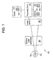
- FIG. 1 illustrates an exemplary X-ray imaging system 100.
- the imaging system 100 includes an X-ray source 102 and a collimator 104, which subject structure under examination 106 to X-ray photons.
- the X-ray source 102 may be an X-ray tube
- the structure under examination 106 may be a human patient, test phantom or other inanimate object under test.
- the X-ray source 102 is able to generate photons at a first energy level and at least a second energy level different than the first energy level. Multiple, more than two, energy levels are also within the scope of this method and system.
- the X-ray imaging system 100 also includes an image sensor 108 coupled to a processing circuit 110.
- the processing circuit 110 e.g., a microcontroller, microprocessor, custom ASIC, or the like
- the processing circuit 110 is coupled to a memory 112 and a display 114.
- the display 114 may include a display device, such as a touch screen monitor with a touch-screen interface.
- the system 100 may include a computer or computer-like object which contains the display 114.
- the computer or computer-like object may include a hard disk, or other fixed, high density media dives, connected using an appropriate device bus, such as a SCSI bus, an Enhanced IDE bus, a PCI bus, etc., a floppy drive, a tape or CD ROM drive with tape or CD media, or other removable media devices, such as magneto-optical media, etc., and a mother board.
- the motherboard includes, for example, a processor, a RAM, and a ROM, I/O ports which are used to couple to the image sensor 108, and optional specialized hardware for performing specialized hardware/software functions, such as sound processing, image processing, signal processing, neural network processing, etc., a microphone, and a speaker or speakers.
- Associated with the computer or computer-like object may be a keyboard for data entry, a pointing device such as a mouse, and a mouse pad or digitizing pad.
- the system and method include programming for controlling both the hardware of the computer and for enabling the computer to interact with a human user.
- Such programming may include, but is not limited to, software for implementation of device drivers, operating systems, and user applications.
- Such computer readable media further includes programming or software instructions to direct the general purpose computer to performance in accordance with the system and method.
- the memory 112 (e.g., including one or more of a hard disk, floppy disk, CDROM, EPROM, and the like) stores a high energy level image 116 (e.g., an image read out from the image sensor 108 after 110-140 kVp 5 mAs exposure) and a low energy level image 118 (e.g., an image read out after 70 kVp 25 mAs exposure).
- Processing circuit 110 provides an image 120 for display on device 114.
- the image 120 may be representative of different structures (e.g., soft-tissue, bone).
- the image sensor 108 may be a flat panel solid state image sensor, for example, although conventional film images stored in digital form in the memory 112 may also be processed as disclosed below as well.
- FIG. 2 depicts a high-level flowchart of exemplary processing performed by the system of FIG. 1.
- the process begins at step 10 with image acquisition.
- An exemplary image acquisition routine is shown in FIG. 3.
- the image acquisition routine includes a technique optimization step 11 that includes processing such as automatic selection of acquisition parameters such as kVp (High and Low), mAs, additional filtration (for example, copper or aluminum), timing, etc.
- the acquisition parameters can be based on variables provided by the user (such as patient size) or obtained automatically by the system (such as variables determined by a low-dose "pre-shot"). Selection of the acquisition parameters may address problems such as residual structures, lung/heart motion, decomposition artifacts and contrast.
- cardiac gating is utilized at step 12.
- Cardiac gating is a technique that triggers the acquisition of images by detector 108 at a specific point in the cardiac cycle. This reduces heart-motion artifacts in views that include the heart, as well as artifacts indirectly related to heart motion such as lung motion. Cardiac gating addresses lung/heart motion artifacts due to heart/aortic pulsatile motion.
- Detector corrections may be applied to both the high energy image and low energy image at steps 15 and 16, respectively.
- Such detector corrections are known in systems employing flat panel detectors and include techniques such as bad pixel/line correction, gain map correction, etc., as well as corrections specific to dual energy imaging such as laggy pixel corrections.
- FIG. 4 is flowchart of an exemplary pre-processing routine.
- the pre-processing includes a scatter correction step 22 which may be implemented in software and/or hardware.
- the scatter correction routine may be applied to each image individually or utilize common information from both the high kVp and the low kVp images to reduce scatter.
- Existing scatter correction techniques may be used such as hardware solutions including specialized anti-scatter grids, and or software solutions using convolution-based or deconvolution-based methods. Additionally, software techniques can utilize information from one image to tune parameters for the other image. Scatter correction addresses decomposition artifacts due to x-ray scatter.
- noise reduction is performed at step 24 where one or more existing noise reduction algorithms are applied to the high kVp and the low kVp images, either individually or simultaneously.
- the noise correction addresses increased noise that may result from the DE decomposition.
- registration is performed to reduce motion artifacts by correcting for motion and aligning anatomies between the high kVp and the low kVp images.
- the registration algorithms may be known rigid-body or warping registration routines applied to the high kVp and the low kVp images.
- the techniques may be iterative and make use of the additional information in decomposed soft-tissue and bone images developed at step 30.
- the registration processing addresses residual structures in the soft-tissue image and/or the bone image and lung/heart motion artifacts.
- step 30 the acquired images are decomposed to generate a raw soft-tissue image and a raw bone image.
- a standard image also referred to as a standard posterior-anterior (PA) image
- PA posterior-anterior
- the decomposition may be performed using known DE radiography techniques. Such techniques may include log-subtraction or basis material decomposition to create raw soft-tissue and raw bone images from the high-energy and low-energy acquisitions.
- Information from the raw soft-tissue image and raw bone image may be used in the registration/motion correction step 26. For example, edge information and/or artifact location information can be derived from the decomposed images for use in the registration/motion correction.
- FIG. 5 is a flowchart of an exemplary post-processing routine.
- the raw soft-tissue image 41 and the raw bone image 42 are subjected to similar processing.
- Contrast matching 43 is performed match contrast of structures in raw soft-tissue image 41 and the raw bone image 42 to the corresponding structures in a standard image.
- contrast of soft-tissue structures in raw soft-tissue image 41 e.g., chest image
- the contrast matching is performed to facilitate interpretation of the x-ray images.
- one or more noise reduction algorithms may be applied to the soft-tissue image 41 and the bone image 42. Existing noise reduction algorithms may be used. The noise reduction addresses noise due to DE decomposition.
- presentation image processing may be performed to the soft-tissue image 41 and the bone image 42. The presentation processing includes processes such as edge enhancement, display window level and window width adjustments for optimal display. The result of the post-processing 40 is depicted as processed soft-tissue image 46 and processed bone image 47.
- step 50 the acquired images are processed for display.
- Computer-aided algorithms have the potential of improving accuracy and reproducibility of disease detection when used in conjunction with visual assessment by radiologists.
- Computer-aided algorithms can be used for detection (presence or absence) or diagnosis (normal or abnormal).
- the detection or diagnosis is performed based upon knowledge acquired by training on a representative sample database.
- the sample data in the database and the features of the data that the algorithms are trained are two important aspects of the training process that affect the performance of CAD algorithms.
- the accuracy of the CAD algorithms improves with improvements on the information it is trained on. With conventional radiographs, overlying and underlying structures confound the relevant information making diagnosis or detection difficult even for computerized algorithms.
- the method and system described herein addresses this problem by using dual energy images, in particular, in conjunction with conventional radiographic images for CAD. In particular, this method combines information from four images to aid computerized detection algorithms.
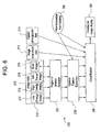
- the dual energy CAD system 200 has several parts including a data source 210, a region of interest 220, optimal feature selection 230, and classification 240, training 250, and display of results 260.
- dual energy CAD 200 may be performed once by incorporating features from all images 215 or may be performed in parallel.
- the parallel operation for a dual energy CAD 201 would involve performing CAD operations, as described in FIG. 6, individually on each image 216, 217, 218, 219 and combining the results of all CAD operations in a synthesis/classification stage 214. That is, the ROI selection 220 can be performed on each image 216, 217, 218, and 219 to provide a low energy image ROI 221, a high energy image ROI 222, a soft tissue image ROI 223, and a bone image ROI 224.
- the optimal feature extraction stage 230 can be performed on each image ROI 221, 222, 223, and 224 to result in low energy image features 231, high energy image features 232, soft tissue image features 233, and bone image features 234.
- the results of all of the CAD operations can be combined.
- FIGS. 6 and 7 show two different methods of performing dual energy CAD, however other methods are also within the scope of this invention such as the ROI selection stage 220 performing in parallel as shown in FIG. 7, but the feature extraction stage 230 performing on a combined ROI such as shown in FIG. 6.
- CAD operations to detect multiple diseases, fractures, or any other medical condition can be performed in series or parallel.
- kVp peak kilovoltage, which determines the maximum energy of the X-rays produced, wherein the amount of radiation produced increases as the square of the kilovoltage
- dose measured in Roentgen as a unit of radiation exposure, rad as a unit of absorbed dose,
- Patient demographics/symptoms/history 214 such as smoking history, sex age, and clinical symptoms may also be a source for data 210.
- Dual energy image sets 215 high energy image 216, low energy image 217, bone image 218, soft tissue image 219, or alternatively stated, first and second decomposed images in lieu of bone image 218 and soft tissue image 219, where first and second decomposed images may include any material images including, but not limited to, soft tissue and bone images
- first and second decomposed images are an additional source of data for the data source 210.
- a region of interest 220 can be defined from which to calculate features.
- the region of interest 220 can be defined several ways. For example, the entire image 215 could be used as the region of interest 220. Alternatively, a part of the image, such as a candidate nodule region in the apical lung field could be selected as the region of interest 220.
- the segmentation of the region of interest 220 can be performed either manually or automatically. The manual segmentation may involve displaying the image and a user delineating the area using, for example, a mouse. An automated segmentation algorithm can use prior knowledge such as the shape and size to automatically delineate the area of interest 220. A semi-automated method which is the combination of the above two methods may also be used.
- the feature selection algorithm 230 is then employed to sort through the candidate features and select only the useful ones and remove those that provide no information or redundant information.
- the feature extraction process, or optimal feature extraction 230 involves performing computations on the data sources 210. For example, on the image-based data 215, the region of interest statistics such as shape, size, density, curvature can be computed. On acquisition-based 212 and patient-based 214 data, the data 212, 214 themselves may serve as the features. As further shown in FIG.
- the multiple feature measures 270 from the high energy image, low energy image, soft image, and bone images or a combination of those images are extracted, for example measured features such as shape, size, texture, intensity, gradient, edge strength, location, proximity, histogram, symmetry, eccentricity, orientation, boundaries, moments, fractals, entropy, etc., patent history such as age, gender, smoking history, and acquisition data such as kVp and dose.
- feature measures thus refers to features which are computed, features which are measured, and features which just exist. A large number of feature measures are included, however the method ensures that only the features which provide relevant information are maintained.
- Step 272 within the feature selection algorithm 230 refers to feature evaluation 272 in terms of its ability to separate the different classification groups using, for example, distance criteria.
- Distance criteria will evaluate how well, using a particular feature, the method can separate the different classes that are used.
- Several different distance criteria can be used such as divergence, Bhattacharya distance, Mahalanobis distance. These techniques are described in "Introduction to Statistical Pattern Recognition", K. Fukanaga, Academic Press, 2 nd ed., 1990, which is herein incorporated by reference.
- Step 274 ranks all the features based on the distance criteria. That is, the features are ranked based on their ability to differentiate between different classes, their discrimination capability.
- the feature selection algorithm 230 is also used to reduce the dimensionality from a practical standpoint, where the computation time might be too long if the number of features to compute is large.
- the dimensionality reduction step 276 refers to how the number of features are reduced by eliminating correlated features. Extra features which are merely providing the same information as other features are eliminated. This provides a reduced set of features which are used by the forward selection step 278 which selects the highest ranked features and then adding additional features, based on a descending ranking, until the performance no longer improves. That is, no more features are added when the point is reached where adding additional features no longer provides any useful information. At this point, the output 280 provides an optimal set of features.
- a pre-trained classification algorithm 240 can be used to classify the regions of interest 220 into benign or malignant nodules, calcifications, fractures or metastases, or whatever classifications are employed for the particular medical condition involved.
- the set of features 280 is used as the input to the classification algorithm 240.
- the normalization of the feature measures from set 280 is performed with respect to feature measures derived from a database of known normal and abnormal cases of interest. This is taken from the prior knowledge from training 250.
- the prior knowledge from training may contain, for example, examples of features of confirmed malignant nodules and examples of features of confirmed benign nodules.
- the training phase 250 may involve, for example, the computation of several candidate features on known samples of benign and malignant nodules.
- Step 284 refers to grouping the normalized feature measures.
- Bayesian classifiers an algorithm for supervised learning that stores a single probabilistic summary for each class and that assumes conditional independence of the attributes given the class
- neural networks which works by creating connections between processing elements whereby the organization and weights of the connections determine the output; neural networks are effective for predicting events when the networks have a large database of prior examples to draw on, and are therefore useful in image recognition systems and medical imaging
- rule-based methods which use conditional statements that tells the system how to react in particular situations
- fuzzy logic which recognizes more than simple true and false values
- clustering techniques and similarity measure approach.
- Dual-energy techniques enable the acquisition of multiple images for review by human or machine observers.
- CAD techniques could operate on one or all of the images 216, 217, 218, and 219, and display the results 260 on each image 216, 217, 218, and 219, or synthesize the results for display 260 onto a single image 215. This would provide the benefit of improving CAD performance by simplifying the segmentation process, while not increasing the quantity of images to be reviewed.
- This display of results 260 forms part of the presentation phase 50 shown in FIG. 2.
- a CAD operation identifies two suspicious lesions characteristic of malignancy on the soft-tissue image 219.
- a CAD operation identifies a calcified nodule (indicating a benign process), and a bone lesion.
- the classification 240 takes these results and determines that one of the soft-tissue nodules is the same as the calcified nodule apparent on the bone-image 218.
- the reviewer would then be presented with the high energy image 216, a first image - taken with a technique to mimic what is currently standard practice for single-energy chest radiography.
- the reviewer would also be presented with a second image, the same image as the first image but with markers indicating the results of the CAD operations 220, 230, 240 superimposed on the image data.
- This second image could be simultaneously displayed on a second hard-or soft-copy image display, or toggled with the other images via software on a soft-copy display.
- Superimposed upon the second image may be, for example, circles around the suspicious lung nodule classified as having characteristics of malignancy, a square around the calcified lung nodules classified as benign, and an arrow pointing to the detected bone lesions.
- the reviewer gets the benefit of the information from CAD operations 200 on each image presented simultaneously for optimal review.
- the methods 200, 201 may be used in mammography. Dual energy imaging for mammography has been previously employed, such as described in U.S. Pat. No. 6,173,034 to Chao.
- the methods 200, 201 may take the results of a dual energy imaging process performed for mammography and employ the CAD techniques as described herein.
- the energies employed in mammography may be as low as 20kVp as opposed to the energies employed typically in the above-described chest exam which may be in the range of 50-170 kVp.
- DE mammographies are typically 24-30kVp, and DE mammographies can be 24-30kVp for the low energy image and 50-80 kVp for the high energy image, where values are often limited by the x-ray tube/generator.
- the energies may be higher, about 80kVp for a conventional single energy image.
- These methods 200, 201 improve the performance of computer-aided detection or diagnosis algorithms by providing input data with overlying structures removed. Also, since the imaged anatomy is separated based on tissue type (soft tissue or bone), this algorithm 200 has the potential of extracting more diagnostic features per anatomy than with standard radiography.
- Previous CR (computed radiography) dual-energy images are of rather poor quality and noisy compared to the standard radiology image and thus computer-aided algorithms have not been previously employed on such images.
- This system and method 200, 201 uses information from high energy image 216, low-energy image 217, soft-tissue image 219, and bone images 218 in addition to acquisition parameters 212 and patient information 214. Furthermore, the results can be displayed to the reviewer without increasing the number of images over that of conventional CAD techniques.
- the above-described methods 200, 201 can additionally be utilized for identification of calcifications, bone fractures, bone erosions, and metastatic bone lesions.
- DE imaging creates an effective opportunity for automatic detection and classification of subtle bone fractures, bone erosions, calcifications and metastases that might otherwise be missed by the standard image reader.
- the method 301 uses a dual energy computer-aided detection/diagnosis (CAD) algorithm 300 for segmenting the bone from the background and detecting/identifying candidate bone regions with possible calcifications, fractures or metastases. These candidate regions are then classified based on features extracted from the corresponding complete image set 215 (high-energy 216, low-energy 217, bone 218, and soft-tissue 219).
- the classification stage not only rules out what it considers false positives, but can also provide additional information about the fracture or lesion (fracture type, lesion size, etc.) The results are then highlighted on the images for the reader to assess.
- the first step in a CAD algorithm 300 for detecting calcifications, bone fractures, bone erosions, and metastases in DE images 215 requires the selection of the desired area to search, or selection of the region of interest (ROI) 310.
- ROI region of interest
- the selection of the region of interest (ROI) 310 can be done manually or by automated algorithms based on user specifications as described above with reference to ROI 220.
- segmentation of bone 320 occurs.
- the purpose of the segmentation 320 is to separate the bone from the background (non-bone).
- One embodiment would be a region-growing algorithm.
- Manual or automated methods can be used for initializing region growing. In manual methods, a means is provided for the user to select the seed point(s). In automated methods, attributes of the bone such as intensity range, gradient range, shape, size etc. can be used for initializing seed points.
- Another potential segmentation method would involve multi-level intensity thresholding.
- candidate regions can be identified in step 330.
- One method for identifying candidate regions is based on an edge detection algorithm. To eliminate noise and false edges, image processing using morphological erosion could follow. In addition, to rule out longer lines that are most likely rib edges, a connectivity algorithm could be applied. Therefore, the remaining image consists of only those edges that are possible candidates for the calcifications, fractures and metastases.
- Candidate regions may then be classified in step 340.
- the classification of the remaining candidate regions may comprise a rule-based approach.
- the rules can be different for identification of calcifications, metastases and fractures. There will preferably be different rules for the different types of fractures, and different rules for the different properties of metastases. For example, for fractures, one might wish to separate the edges inside the ribs from the edges outside the ribs, as edges inside the ribs are candidates for fractures. Rules could also be based on size measurements of the line edges.
- Remaining candidate regions should then be indicated to the user or reader for inspection in a presentation step, or indication of results 350. This could be performed by highlighting areas on the original bone image, either with arrows, circles, or some other indicator or marker. Additional information such as lesion type or size can also be overlaid on the images.
- the indication of results 350 may then be read by a radiologist or clinician in step 360 and this method 301 can be used to improve the detection of calcifications, subtle rib fractures, subtle bone erosions, and metastatic bone lesions in chest radiography as exemplified by step 370.
- the detection of such ailments can lead to increased benefit to the patient by early detection, leading to improved patient care by the clinician.
- the ability to provide a bone image without over/underlying soft-tissue can also be used to greatly improve detection and diagnosis of bone-related pathology.
- Using the bone image for calcifications, fracture and metastases detection is a diagnostic concept for DE imaging which has not previously been available.
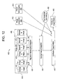
- a multiple energy imaging system 400 is shown in FIG. 12, which is similar to the DE imaging systems 200, 201, and 300 as described above in that in includes a data source 410 including image data 415, image acquisition data 412, and patient demographic data 414, defining or selecting a region of interest 420, optimal feature extraction 430, synthesis/classification 440, and overlay on image display 460. Also as in the previously described DE imaging systems, prior knowledge from training 450 is applied to the optimal feature extraction stage 430 and the synthesis/classification stage 440. Thus, the only distinction between the method 400 and the previously described DE methods is the content of the image data 415.
- the multiple energy imaging system 400 uses a series of images 413 taken at different energies/kVps (Energy 1 image, Energy 2 image, ... Energy N image). It should be noted that "N” denotes an arbitrary number and may change from one imaging process to the next. While these images 413 can be acquired in a rapid sequence and decomposed into a bone image 418 and different tissue type images, they may also be decomposed into different material images (material 1 image, material 2 image, ... material N image) which may or may not include a bone image. Information from one or more of these images can be used to detect and diagnose various diseases or medical conditions.
- regions of interest can be identified and features can be computed on material 2 image and the Energy 1 image.
- all the images may be used.
- region of interest selection, optimal feature computation, and classification may be performed in series or in parallel on the image data 415.
- “multiple" energy imaging may encompass dual energy imaging, since two images are multiple images.
- pre-reconstruction analysis and post-reconstruction analysis are prior art techniques generally recognized for using dual energy X-ray sources in materials analysis.
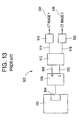
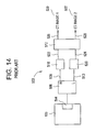
- the signal flow is as shown in FIG. 13.
- the system 100 is typically similar to the one shown in FIG. 1 and has an X-ray source capable of producing a fan beam at two distinct energy levels (i.e., dual energy).
- the data acquisition system 504 gathers signals generated by detector array at discrete angular positions of the rotating platform (not shown) and passes the signals to the pre-processing element 506.
- the pre-processing element 506 re-sorts the data it receives from the data acquisition system 504 in order to optimize the sequence for the subsequent mathematical processing.
- the pre-processing element 506 also corrects the data from the data acquisition system 504 for detector temperature, intensity of the primary beam, gain and offset, and other deterministic error factors.
- the pre-processing element 506 extracts data corresponding to high-energy views and routes it to a high energy channel path 508, and routes the data corresponding to low-energy views to a low energy path 510.
- the projection computer 512 receives the projection data on the high energy path 508 and the low energy path 510 and performs Alvarez/Macovski Algorithm processing to produce a first stream of projection data 514 which is dependent on a first parameter of the material being scanned and a second stream of projection data 516 which is dependent on a second parameter of the material scanned.
- the first parameter is often the atomic number and the second parameter is often material density, although other parameters may be selected.
- a first reconstruction computer 518 receives the first stream of projection data 514 and generates a CT image from the series of projections corresponding to the first material parameter.
- a second reconstruction computer 520 receives the second stream of projection data 516 and generates a CT image from the series projections corresponding to the second material parameter.
- a pre-processing element 506 receives data from a data acquisition system 504, performs several operations upon the data, then routes the data corresponding to high-energy views to a high energy path 508 and routes the data corresponding to low-energy views to a low energy path 510.
- a first reconstruction computer 518 receives the projection data from the high energy path 508 and generates a CT image corresponding to the high-energy series of projections.
- a second reconstruction computer 520 receives the projection data fro the low-energy path 510 and generates a CT image corresponding to the low-energy series of projections.
- a projection computer 512 receives the high energy CT data 522 and the low-energy CT data 524 and performs basis material decomposition to product CT data 526 which is dependent on a first parameter of the material being scanned and a second stream of projection data 528 which is dependent on a second parameter of the material scanned.
- FIG. 15 shows the method of computer aided detection and diagnosis 202 revised for dual energy CT imaging.
- the method 202 is similar to the method 200 described with respect to FIG. 6, except that multiple CT images 1a, ... 1N 530 or 534 and multiple CT images 2a, ... 2N 532 or 536, as described above with respect to either FIGS. 13 or 14, replace high energy image 216 and low energy image 217 to form image set 540.
- N may denote any arbitrary number and need not be the same number as the "N" in FIG. 12.
- the image data 540 could instead include first decomposed images and second decomposed images, as previously described with respect to FIG. 6.
- the CAD method 201 shown in FIG. 7 could also be revised for dual energy CT.
- volume CT or cone-beam CT
- Fan-beam tomography a fan collection of X-rays are generated by placing a collimator with a long and narrow slot in front of a point X-ray source.
- a cone-beam family of x-rays is made by removing the collimator. This allows the x-rays to diverge from the point x-ray source to form a cone-like solid angle.
- a divergent line integral data set results when the x-rays, which penetrate the object, are collected by a detector located on the opposite side.
- Cone-beam tomography involves inverting the cone-beam data set to form an estimate of the density of each point inside the object.
- FIG. 16 shows a CAD system 600 which uses Volume CT images 1 ... N for image data 615 such that data source 610 includes volume CT images 615, image acquisition data 212, and patient demographic data 214. Otherwise, the CAD system is similar to system 200 described with respect to FIG. 6. Alternatively, the operations 220. 230, 240 may be performed in parallel on each volume CT image as described with respect to FIG. 7.
- a dual energy CAD system 700 uses high and low energy Volume CT images 1a... 1N 716 and 2a...2N 717, respectively, as well as soft tissue images 1... N 219 and bone images 1... N 218 (or alternatively first decomposed images and second decomposed images) as image data 715, such that data source 710 includes image data 715, image acquisition data 212, and patient demographic data 214.
- the CAD system 700 is similar to system 200 described with respect to FIG. 6.
- the operations 220, 230, 240 may be performed in parallel on each Volume CT image and each soft tissue image and bone image as described with respect to FIG. 7.
- volume CT CAD 600 and DE Volume CT CAD 700 are described in FIGS. 16 and 17, it is further contemplated that multiple energy Volume CT CAD may be employed using the methods described with respect to FIG. 12, that is, the method shown in FIG. 17 may be expanded to incorporate additional energies.
- an imaging mode where limited angle x-ray tomosynthesis acquisition is performed and reconstructed may be combined with the computer aided detection and diagnosis methods described above and as shown in FIG. 18.
- Tomosynthesis is performed by acquiring multiple images with a digital detector, i.e. series of low dose images used to reconstruct tomography images at any level. Tomosynthesis may be performed using many different tube motions including linear, circular, elliptical, hypocycloidal, and others.
- image sequences are acquired, with typical number of images ranging from 5 to 50.
- the imaging portion of this embodiment may be less expensive, although not necessarily preferred, over the CAD CT methods described above.
- the tomosynthesis CAD system 800 shown in FIG. 18 is similar to the CT CAD system shown in FIG.
- the system 800 is similar to system 200 described with respect to FIG. 6.
- the operations 220, 230, 240 may be performed in parallel on each tomosynthesis image as described with respect to FIG. 7.
- a dual energy CAD system 900 uses high and low energy tomosynthesis images 1a...1N 916 and 2a...2N 917, respectively, as well as soft tissue images 1... N 219 and bone images 1 ... N 218 (or alternatively first decomposed images and second decomposed images) as image data 915, such that data source 910 includes image data 915, image acquisition data 212, and patient demographic data 214.
- the CAD system 900 is similar to system 200 described with respect to FIG. 6.
- the operations 220, 230, 240 may be performed in parallel on each tomosynthesis image and each soft tissue image and bone image as described with respect to FIG. 7.
- tomosynthesis CAD 800 and DE tomosynthesis CAD 900 are described in FIGS. 18 and 19, it is further contemplated that multiple energy tomosynthesis CAD may be employed using the methods described with respect to FIG. 12, that is, the method shown in FIG. 19 may be expanded to incorporate additional energies.
- the present invention can also be embodied in the form of computer program code, for example, whether stored in a storage medium, loaded into and/or executed by a computer, or as data signal transmitted whether a modulated carrier wave or not, over some transmission medium, such as over electrical wiring or cabling, through fiber optics, or via electromagnetic radiation, wherein, when the computer program code is loaded into and executed by a computer, the computer becomes an apparatus for practicing the invention.
- the computer program code segments configure the microprocessor to create specific logic circuits.
Landscapes
- Health & Medical Sciences (AREA)
- Engineering & Computer Science (AREA)
- Medical Informatics (AREA)
- Life Sciences & Earth Sciences (AREA)
- General Health & Medical Sciences (AREA)
- Public Health (AREA)
- Physics & Mathematics (AREA)
- Nuclear Medicine, Radiotherapy & Molecular Imaging (AREA)
- Radiology & Medical Imaging (AREA)
- Biomedical Technology (AREA)
- Pathology (AREA)
- Heart & Thoracic Surgery (AREA)
- Veterinary Medicine (AREA)
- High Energy & Nuclear Physics (AREA)
- Biophysics (AREA)
- Molecular Biology (AREA)
- Surgery (AREA)
- Animal Behavior & Ethology (AREA)
- Optics & Photonics (AREA)
- General Physics & Mathematics (AREA)
- Theoretical Computer Science (AREA)
- Epidemiology (AREA)
- Primary Health Care (AREA)
- Quality & Reliability (AREA)
- Computer Vision & Pattern Recognition (AREA)
- Orthopedic Medicine & Surgery (AREA)
- Dentistry (AREA)
- Oral & Maxillofacial Surgery (AREA)
- Data Mining & Analysis (AREA)
- Databases & Information Systems (AREA)
- Apparatus For Radiation Diagnosis (AREA)
Abstract
Description
Claims (10)
- A method (200, 201, 202, 300, 400, 700, 900) for computer aided processing of dual or multiple energy images, the method comprising:employing a data source (210, 410, 710 910), the data source (210, 410, 710 910) including a dual or multiple energy image set (215, 415, 540, 715, 915) including a high energy image (216, 530, 534, 716, 916), a low energy image (217, 532, 536, 717, 917), a bone image (218), and a soft tissue image (219);defining a region of interest (220) within an image from the dual or multiple energy image set (215, 415, 540, 715, 915);extracting (230) feature measures from the region of interest (220); and,reporting (260) at least one of the feature measures on the region of interest (220).
- The method (202) of claim 1 further comprising acquiring the image set (540) using x-ray computed tomography.
- The method (900) of claim 1 further comprising acquiring the image set (915) using digital x-ray tomosynthesis.
- The method (200, 201, 202, 300, 400, 700, 900) of claim 1 further comprising employing a feature selection algorithm (230) on the region of interest (220) and classifying (240) the region of interest (220).
- A system (100) for computer aided processing of dual energy images, the system (100) comprising:a detector (108) generating a first image representative of photons at a first energy level passing through a structure (106) and a second image representative of photons at a second energy level passing through the structure (106);a memory (112) coupled to the detector (108), the memory (112) storing the first image and the second image;a processing circuit (110) coupled to the memory (112), the processing circuit (110) processing a dual energy image set (215, 415, 540, 715, 915) including a first decomposed image, a second decomposed image, a high energy image, and a low energy image from the first image and the second image, storing the dual energy image set in the memory (112) as a data source (210), defining a region of interest (220) within an image from the dual energy image set (215, 415, 540, 715, 915), and extracting feature measures (230) from the region of interest (220); and,a reporting device (114) coupled to the processing circuit (110), the reporting device (114) reporting at least one of the feature measures.
- A system (100) for computer aided processing of dual energy images, the system (100) comprising:detection means (108) for generating a first image representative of photons at a first energy level passing through a structure (106) and a second image representative of photons at a second energy level passing through the structure (106);storage means (112) for storing the first image and the second image (215, 415, 540, 715, 915);processing means (110) for processing a dual energy image set (215, 415, 540, 715, 915) including a first decomposed image, a second decomposed image, a high energy image, and a low energy image from the first image and the second image, storing the dual energy image set in the memory (112) as a data source (210), defining a region of interest (220) within an image from the dual energy image set (215, 415, 540, 715, 915), extracting feature measures (230) from the region of interest (220), employing a feature selection algorithm (230) on the set of feature measures and identifying an optimal set of features, classifying (240) the optimal set of features, and incorporating prior knowledge from training (250) into classifying (240) the optimal set of features; and,display means (260) for displaying the classified optimal set of features.
- A storage medium encoded with a machine readable computer program code, said code including instructions for causing a computer to implement a method (200, 201, 202, 300, 400, 700, 900) for aiding in processing of dual or multiple energy images, the method comprising:employing a data source (210, 710, 910), the data source (210, 710, 910) including a dual or multiple energy image set (215, 415, 540, 715, 915) having a first decomposed image, a second decomposed image, a high energy image, and a low energy image;defining a region of interest (220) within an image from the dual or multiple energy image set (215, 415, 540, 715, 915);extracting feature measures (230) from the region of interest (220); and,employing a feature selection algorithm (230) on the feature measures for identifying an optimal set of features.
- A method (202) for computer aided processing of computed tomography images, the method (202) comprising:acquiring an image set (540) of dual energy computed tomography images;employing a data source, the data source including the image set (540);defining a region of interest (220) within an image from the image set (540);extracting feature measures (230) from the region of interest (220); and,reporting (260) at least one of the feature measures on the region of interest (220).
- A method (600, 700) for computer aided processing of volumetric computed tomography images, the method (600, 700) comprising:acquiring an image set (615, 715) of volumetric computed tomography images;employing a data source (610, 710), the data source (610, 710) including the image set (615, 715);defining a region of interest (220) within an image from the image set (615, 715);extracting feature measures (230) from the region of interest (220); and,reporting (260) at least one of the feature measures on the region of interest (220).
- A method (800, 900) for computer aided processing of x-ray tomosynthesis images, the method (800, 900) comprising:acquiring an image set (815, 915) of tomosynthesis images;employing a data source (810, 910), the data source (810, 910) including the image set (815, 915);defining a region of interest (220) within an image from the image set (815, 915);extracting (230) feature measures from the region of interest (220); and,reporting (260) at least one of the feature measures on the region of interest (220).
Applications Claiming Priority (2)
| Application Number | Priority Date | Filing Date | Title |
|---|---|---|---|
| US10/065,854 US7295691B2 (en) | 2002-05-15 | 2002-11-26 | Computer aided diagnosis of an image set |
| US65854 | 2002-11-26 |
Publications (2)
| Publication Number | Publication Date |
|---|---|
| EP1426903A2 true EP1426903A2 (en) | 2004-06-09 |
| EP1426903A3 EP1426903A3 (en) | 2006-02-08 |
Family
ID=32311671
Family Applications (1)
| Application Number | Title | Priority Date | Filing Date |
|---|---|---|---|
| EP03256209A Withdrawn EP1426903A3 (en) | 2002-11-26 | 2003-10-01 | Computer aided diagnosis of an image set |
Country Status (5)
| Country | Link |
|---|---|
| US (2) | US7295691B2 (en) |
| EP (1) | EP1426903A3 (en) |
| JP (1) | JP2004174232A (en) |
| KR (1) | KR20040047561A (en) |
| CN (1) | CN1504931B (en) |
Cited By (34)
| Publication number | Priority date | Publication date | Assignee | Title |
|---|---|---|---|---|
| DE102004051401A1 (en) * | 2004-10-21 | 2006-05-24 | Siemens Ag | Method for diagnosis in three-dimensional imaging, in particular in mammography |
| DE102005022543A1 (en) * | 2005-05-17 | 2006-11-23 | Siemens Ag | Mammography procedure and mammography device |
| EP1734405A2 (en) | 2005-06-14 | 2006-12-20 | Canon Kabushiki Kaisha | Radiographic imaging apparatus, control method thereof, and radiographic imaging system |
| DE102006037063A1 (en) * | 2006-08-08 | 2008-02-21 | Siemens Ag | Method for generating a medical image and data processing unit and computer software for this purpose |
| WO2008064398A1 (en) * | 2006-11-28 | 2008-06-05 | Orthonova Pty Ltd | Diagnostic system |
| WO2008100471A1 (en) * | 2007-02-12 | 2008-08-21 | Carestream Health, Inc. | Renormalization of dual-energy images |
| WO2008035266A3 (en) * | 2006-09-21 | 2009-01-29 | Koninkl Philips Electronics Nv | Automatic seed point selection |
| CN100471453C (en) * | 2005-06-14 | 2009-03-25 | 佳能株式会社 | Radiographic imaging apparatus, control method thereof, and radiographic imaging system |
| WO2009084995A1 (en) * | 2007-12-28 | 2009-07-09 | Exini Diagnostics Ab | System for detecting bone cancer metastases |
| WO2010017729A1 (en) * | 2008-08-13 | 2010-02-18 | 清华大学 | Method for image reconstruction in the high energy dual energy ct system |
| NL2003843A (en) * | 2008-11-26 | 2010-05-27 | Gen Electric | Systems and methods for displaying multi-energy data. |
| US7860283B2 (en) | 2006-10-25 | 2010-12-28 | Rcadia Medical Imaging Ltd. | Method and system for the presentation of blood vessel structures and identified pathologies |
| US7873194B2 (en) | 2006-10-25 | 2011-01-18 | Rcadia Medical Imaging Ltd. | Method and system for automatic analysis of blood vessel structures and pathologies in support of a triple rule-out procedure |
| US7940970B2 (en) | 2006-10-25 | 2011-05-10 | Rcadia Medical Imaging, Ltd | Method and system for automatic quality control used in computerized analysis of CT angiography |
| US7940977B2 (en) | 2006-10-25 | 2011-05-10 | Rcadia Medical Imaging Ltd. | Method and system for automatic analysis of blood vessel structures to identify calcium or soft plaque pathologies |
| WO2011073818A1 (en) * | 2009-12-15 | 2011-06-23 | Koninklijke Philips Electronics N.V. | Motion compensation with tissue density retention |
| US8103074B2 (en) | 2006-10-25 | 2012-01-24 | Rcadia Medical Imaging Ltd. | Identifying aorta exit points from imaging data |
| WO2012025855A1 (en) * | 2010-08-25 | 2012-03-01 | Koninklijke Philips Electronics N.V. | Dual modality imaging including quality metrics |
| WO2012080914A1 (en) * | 2010-12-13 | 2012-06-21 | Koninklijke Philips Electronics N.V. | Breast density assessment |
| CN101664318B (en) * | 2008-09-03 | 2013-07-17 | 爱克发医疗保健公司 | Method for deriving the amount of dense tissue from a digital mammographic image representation |
| US10340046B2 (en) | 2016-10-27 | 2019-07-02 | Progenics Pharmaceuticals, Inc. | Network for medical image analysis, decision support system, and related graphical user interface (GUI) applications |
| US10973486B2 (en) | 2018-01-08 | 2021-04-13 | Progenics Pharmaceuticals, Inc. | Systems and methods for rapid neural network-based image segmentation and radiopharmaceutical uptake determination |
| US11321844B2 (en) | 2020-04-23 | 2022-05-03 | Exini Diagnostics Ab | Systems and methods for deep-learning-based segmentation of composite images |
| US11386988B2 (en) | 2020-04-23 | 2022-07-12 | Exini Diagnostics Ab | Systems and methods for deep-learning-based segmentation of composite images |
| US11534125B2 (en) | 2019-04-24 | 2022-12-27 | Progenies Pharmaceuticals, Inc. | Systems and methods for automated and interactive analysis of bone scan images for detection of metastases |
| US11544407B1 (en) | 2019-09-27 | 2023-01-03 | Progenics Pharmaceuticals, Inc. | Systems and methods for secure cloud-based medical image upload and processing |
| US11564621B2 (en) | 2019-09-27 | 2023-01-31 | Progenies Pharmacenticals, Inc. | Systems and methods for artificial intelligence-based image analysis for cancer assessment |
| US11657508B2 (en) | 2019-01-07 | 2023-05-23 | Exini Diagnostics Ab | Systems and methods for platform agnostic whole body image segmentation |
| US11721428B2 (en) | 2020-07-06 | 2023-08-08 | Exini Diagnostics Ab | Systems and methods for artificial intelligence-based image analysis for detection and characterization of lesions |
| US11900597B2 (en) | 2019-09-27 | 2024-02-13 | Progenics Pharmaceuticals, Inc. | Systems and methods for artificial intelligence-based image analysis for cancer assessment |
| US11948283B2 (en) | 2019-04-24 | 2024-04-02 | Progenics Pharmaceuticals, Inc. | Systems and methods for interactive adjustment of intensity windowing in nuclear medicine images |
| US12417533B2 (en) | 2019-09-27 | 2025-09-16 | Progenics Pharmaceuticals, Inc. | Systems and methods for artificial intelligence-based image analysis for cancer assessment |
| US12597127B2 (en) | 2021-10-08 | 2026-04-07 | Exini Diagnostics Ab | Systems and methods for automated identification and classification of lesions in local lymph and distant metastases |
| US12602772B2 (en) | 2018-01-08 | 2026-04-14 | Progenics Pharmaceuticals, Inc. | Systems and methods for rapid neural network-based image segmentation and radiopharmaceutical uptake determination |
Families Citing this family (236)
| Publication number | Priority date | Publication date | Assignee | Title |
|---|---|---|---|---|
| US6836528B2 (en) * | 2002-07-23 | 2004-12-28 | Ge Medical Systems Global Technology Company, Llc | Methods and apparatus for detecting structural, perfusion, and functional abnormalities |
| US6891922B2 (en) * | 2002-11-22 | 2005-05-10 | Ge Medical Systems Global Technology Company, Llc | Methods and apparatus for the classification of nodules |
| US8571289B2 (en) | 2002-11-27 | 2013-10-29 | Hologic, Inc. | System and method for generating a 2D image from a tomosynthesis data set |
| US8565372B2 (en) | 2003-11-26 | 2013-10-22 | Hologic, Inc | System and method for low dose tomosynthesis |
| US7123684B2 (en) | 2002-11-27 | 2006-10-17 | Hologic, Inc. | Full field mammography with tissue exposure control, tomosynthesis, and dynamic field of view processing |
| US7616801B2 (en) | 2002-11-27 | 2009-11-10 | Hologic, Inc. | Image handling and display in x-ray mammography and tomosynthesis |
| US10638994B2 (en) | 2002-11-27 | 2020-05-05 | Hologic, Inc. | X-ray mammography with tomosynthesis |
| US7577282B2 (en) | 2002-11-27 | 2009-08-18 | Hologic, Inc. | Image handling and display in X-ray mammography and tomosynthesis |
| JP4253497B2 (en) * | 2002-12-03 | 2009-04-15 | 株式会社東芝 | Computer-aided diagnosis device |
| US20040122702A1 (en) * | 2002-12-18 | 2004-06-24 | Sabol John M. | Medical data processing system and method |
| US20040122706A1 (en) * | 2002-12-18 | 2004-06-24 | Walker Matthew J. | Patient data acquisition system and method |
| US7187790B2 (en) * | 2002-12-18 | 2007-03-06 | Ge Medical Systems Global Technology Company, Llc | Data processing and feedback method and system |
| US20040122704A1 (en) * | 2002-12-18 | 2004-06-24 | Sabol John M. | Integrated medical knowledge base interface system and method |
| US20040122707A1 (en) * | 2002-12-18 | 2004-06-24 | Sabol John M. | Patient-driven medical data processing system and method |
| US20040122708A1 (en) * | 2002-12-18 | 2004-06-24 | Avinash Gopal B. | Medical data analysis method and apparatus incorporating in vitro test data |
| US7490085B2 (en) | 2002-12-18 | 2009-02-10 | Ge Medical Systems Global Technology Company, Llc | Computer-assisted data processing system and method incorporating automated learning |
| US20040122787A1 (en) * | 2002-12-18 | 2004-06-24 | Avinash Gopal B. | Enhanced computer-assisted medical data processing system and method |
| US20040122705A1 (en) * | 2002-12-18 | 2004-06-24 | Sabol John M. | Multilevel integrated medical knowledge base system and method |
| US20040122709A1 (en) * | 2002-12-18 | 2004-06-24 | Avinash Gopal B. | Medical procedure prioritization system and method utilizing integrated knowledge base |
| US7616818B2 (en) * | 2003-02-19 | 2009-11-10 | Agfa Healthcare | Method of determining the orientation of an image |
| US6873677B2 (en) * | 2003-04-18 | 2005-03-29 | Leon Kaufman | Method and device for improving time resolution of an imaging device |
| GB0525593D0 (en) | 2005-12-16 | 2006-01-25 | Cxr Ltd | X-ray tomography inspection systems |
| US8243876B2 (en) | 2003-04-25 | 2012-08-14 | Rapiscan Systems, Inc. | X-ray scanners |
| JP4118786B2 (en) * | 2003-11-14 | 2008-07-16 | ジーイー・メディカル・システムズ・グローバル・テクノロジー・カンパニー・エルエルシー | Imaging support system |
| US20050123185A1 (en) * | 2003-11-26 | 2005-06-09 | Ram Balasubramanian | Computer aided detection workflow and user interface |
| US8768026B2 (en) | 2003-11-26 | 2014-07-01 | Hologic, Inc. | X-ray imaging with x-ray markers that provide adjunct information but preserve image quality |
| WO2005055140A1 (en) * | 2003-12-02 | 2005-06-16 | Philips Intellectual Property & Standards Gmbh | A device and method for correcting defects in x-ray images |
| US8442280B2 (en) * | 2004-01-21 | 2013-05-14 | Edda Technology, Inc. | Method and system for intelligent qualitative and quantitative analysis of digital radiography softcopy reading |
| US7616794B2 (en) * | 2004-01-26 | 2009-11-10 | Siemens Medical Solutions Usa, Inc. | System and method for automatic bone extraction from a medical image |
| US7072435B2 (en) * | 2004-01-28 | 2006-07-04 | Ge Medical Systems Global Technology Company, Llc | Methods and apparatus for anomaly detection |
| US7406187B2 (en) * | 2004-02-23 | 2008-07-29 | Canon Kabushiki Kaisha | Method and system for processing an image |
| US8064660B2 (en) * | 2004-02-27 | 2011-11-22 | National University Of Singapore | Method and system for detection of bone fractures |
| JP4647360B2 (en) * | 2004-04-05 | 2011-03-09 | 富士フイルム株式会社 | DIFFERENTIAL IMAGE CREATION DEVICE, DIFFERENTIAL IMAGE CREATION METHOD, AND PROGRAM THEREOF |
| CN101420905B (en) * | 2004-04-14 | 2013-01-02 | 美国医软科技公司 | Method and system for quality assurance of lesion labeling and characterization |
| US7835562B2 (en) | 2004-07-23 | 2010-11-16 | General Electric Company | Methods and apparatus for noise reduction filtering of images |
| US9155373B2 (en) * | 2004-08-02 | 2015-10-13 | Invention Science Fund I, Llc | Medical overlay mirror |
| EP1632178A1 (en) * | 2004-09-03 | 2006-03-08 | ndd Medizintechnik AG | Method for non-cooperative lung function diagnosis using ultrasound |
| FR2875693B1 (en) * | 2004-09-24 | 2006-12-08 | Gen Electric | X-RAY TOMOGRAPHY DEVICE |
| US7352885B2 (en) * | 2004-09-30 | 2008-04-01 | General Electric Company | Method and system for multi-energy tomosynthesis |
| US7787672B2 (en) | 2004-11-04 | 2010-08-31 | Dr Systems, Inc. | Systems and methods for matching, naming, and displaying medical images |
| US7920152B2 (en) | 2004-11-04 | 2011-04-05 | Dr Systems, Inc. | Systems and methods for viewing medical 3D imaging volumes |
| US7970625B2 (en) | 2004-11-04 | 2011-06-28 | Dr Systems, Inc. | Systems and methods for retrieval of medical data |
| US7660488B2 (en) | 2004-11-04 | 2010-02-09 | Dr Systems, Inc. | Systems and methods for viewing medical images |
| US7662082B2 (en) | 2004-11-05 | 2010-02-16 | Theragenics Corporation | Expandable brachytherapy device |
| EP2602743B1 (en) | 2004-11-15 | 2014-11-05 | Hologic, Inc. | Matching geometry generation and display of mammograms and tomosynthesis images |
| EP1813136A4 (en) * | 2004-11-18 | 2008-12-17 | Compumed Inc | Methods and systems for analyzing bone conditions using mammography device |
| EP1815392A1 (en) * | 2004-11-23 | 2007-08-08 | Eastman Kodak Company | Automated radiograph classification using anatomy information |
| CN101065778A (en) * | 2004-11-23 | 2007-10-31 | 伊斯曼柯达公司 | Method for classifying radiographs |
| EP3106094B1 (en) | 2004-11-26 | 2021-09-08 | Hologic, Inc. | Integrated multi-mode mammography/tomosynthesis x-ray system |
| US20060136259A1 (en) * | 2004-12-17 | 2006-06-22 | General Electric Company | Multi-dimensional analysis of medical data |
| US20060136417A1 (en) * | 2004-12-17 | 2006-06-22 | General Electric Company | Method and system for search, analysis and display of structured data |
| US7729523B2 (en) * | 2004-12-21 | 2010-06-01 | General Electric Company | Method and system for viewing image data |
| US20060247544A1 (en) * | 2005-02-03 | 2006-11-02 | Maleeha Qazi | Characterization of cardiac motion with spatial relationship |
| JP4664158B2 (en) * | 2005-09-01 | 2011-04-06 | 富士通株式会社 | Authentication processing method and authentication server |
| US20070078873A1 (en) * | 2005-09-30 | 2007-04-05 | Avinash Gopal B | Computer assisted domain specific entity mapping method and system |
| EP1780651A1 (en) * | 2005-10-25 | 2007-05-02 | Bracco Imaging, S.P.A. | Method and system for automatic processing and evaluation of images, particularly diagnostic images |
| WO2013078476A1 (en) | 2011-11-27 | 2013-05-30 | Hologic, Inc. | System and method for generating a 2d image using mammography and/or tomosynthesis image data |
| US10008184B2 (en) | 2005-11-10 | 2018-06-26 | Hologic, Inc. | System and method for generating a 2D image using mammography and/or tomosynthesis image data |
| US7465268B2 (en) | 2005-11-18 | 2008-12-16 | Senorx, Inc. | Methods for asymmetrical irradiation of a body cavity |
| US8005278B2 (en) * | 2005-11-22 | 2011-08-23 | General Electric Company | System and method for patient acuity driven workflow using computer-aided diagnosis of medical images |
| DE102005060311A1 (en) * | 2005-12-16 | 2007-06-21 | Siemens Ag | Device for visualizing object properties |
| JP4690204B2 (en) * | 2006-01-16 | 2011-06-01 | 富士フイルム株式会社 | Image reproduction apparatus and program thereof |
| US7986827B2 (en) * | 2006-02-07 | 2011-07-26 | Siemens Medical Solutions Usa, Inc. | System and method for multiple instance learning for computer aided detection |
| US20070189455A1 (en) * | 2006-02-14 | 2007-08-16 | Accuray Incorporated | Adaptive x-ray control |
| WO2007095330A2 (en) | 2006-02-15 | 2007-08-23 | Hologic Inc | Breast biopsy and needle localization using tomosynthesis systems |
| JP5214110B2 (en) * | 2006-03-07 | 2013-06-19 | ジーイー・メディカル・システムズ・グローバル・テクノロジー・カンパニー・エルエルシー | X-ray CT system |
| DE102006013472A1 (en) * | 2006-03-23 | 2007-09-20 | Siemens Ag | Method and device for processing image data for automatic detection and / or segmentation of anatomical features from computed tomography images |
| DE102006021373A1 (en) * | 2006-05-08 | 2007-11-15 | Siemens Ag | X-ray diagnostic device |
| US7940955B2 (en) * | 2006-07-26 | 2011-05-10 | Delphi Technologies, Inc. | Vision-based method of determining cargo status by boundary detection |
| JP5196751B2 (en) * | 2006-09-13 | 2013-05-15 | 株式会社東芝 | Computer-aided diagnosis device |
| US20080089584A1 (en) * | 2006-10-13 | 2008-04-17 | Vanmetter Richard L | Viewing glass display for multi-component images |
| US7953614B1 (en) | 2006-11-22 | 2011-05-31 | Dr Systems, Inc. | Smart placement rules |
| JP4575909B2 (en) * | 2006-11-22 | 2010-11-04 | ジーイー・メディカル・システムズ・グローバル・テクノロジー・カンパニー・エルエルシー | X-ray tomography equipment |
| JP4992456B2 (en) * | 2007-02-16 | 2012-08-08 | コニカミノルタエムジー株式会社 | Bone disease evaluation system |
| JP2008229122A (en) * | 2007-03-22 | 2008-10-02 | Fujifilm Corp | Image component separation apparatus, method, and program |
| JP4895204B2 (en) * | 2007-03-22 | 2012-03-14 | 富士フイルム株式会社 | Image component separation device, method, and program, and normal image generation device, method, and program |
| US8816959B2 (en) * | 2007-04-03 | 2014-08-26 | General Electric Company | Method and apparatus for obtaining and/or analyzing anatomical images |
| US20080253525A1 (en) * | 2007-04-11 | 2008-10-16 | Boyden Edward S | Compton scattered x-ray visualizing, imaging, or information providing of at least some dissimilar matter |
| US8837677B2 (en) * | 2007-04-11 | 2014-09-16 | The Invention Science Fund I Llc | Method and system for compton scattered X-ray depth visualization, imaging, or information provider |
| US8041006B2 (en) * | 2007-04-11 | 2011-10-18 | The Invention Science Fund I Llc | Aspects of compton scattered X-ray visualization, imaging, or information providing |
| US20080253526A1 (en) * | 2007-04-11 | 2008-10-16 | Searete Llc, A Limited Liability Corporation Of The State Of Delaware | Geometric compton scattered x-ray visualizing, imaging, or information providing |
| US7734012B2 (en) * | 2007-04-11 | 2010-06-08 | The Invention Science Fund I, Llc | Volumetric type compton scattered X-ray visualization, imaging, or information provider |
| US20080253522A1 (en) * | 2007-04-11 | 2008-10-16 | Searete Llc, A Limited Liability Corporation Of The State Of Delaware | Tool associated with compton scattered X-ray visualization, imaging, or information provider |
| US8098917B2 (en) * | 2007-05-18 | 2012-01-17 | Siemens Aktiengesellschaft | Automatically updating a geometric model |
| US9532750B2 (en) * | 2007-07-13 | 2017-01-03 | Mayo Foundation For Medical Education And Research | Object identification in dual energy contrast-enhanced CT images |
| FR2919747B1 (en) * | 2007-08-02 | 2009-11-06 | Gen Electric | METHOD AND SYSTEM FOR DISPLAYING TOMOSYNTHESIS IMAGES |
| US20090060366A1 (en) * | 2007-08-27 | 2009-03-05 | Riverain Medical Group, Llc | Object segmentation in images |
| ATE554465T1 (en) * | 2007-09-10 | 2012-05-15 | Koninkl Philips Electronics Nv | IMAGE PROCESSING USING COMPUTER-ASSISTED RECOGNITION AND/OR DIAGNOSIS |
| US7630533B2 (en) | 2007-09-20 | 2009-12-08 | Hologic, Inc. | Breast tomosynthesis with display of highlighted suspected calcifications |
| JP4829198B2 (en) * | 2007-10-23 | 2011-12-07 | 日立アロカメディカル株式会社 | Bone measuring apparatus and bone image processing method |
| US20100259263A1 (en) * | 2007-11-14 | 2010-10-14 | Dominic Holland | Longitudinal registration of anatomy in magnetic resonance imaging |
| KR101129718B1 (en) * | 2008-01-04 | 2012-03-28 | 주식회사 메디칼스탠다드 | Reading aid method of digital test images |
| JP5329103B2 (en) * | 2008-02-01 | 2013-10-30 | ジーイー・メディカル・システムズ・グローバル・テクノロジー・カンパニー・エルエルシー | Image processing apparatus and X-ray CT apparatus |
| CN101502420B (en) * | 2008-02-05 | 2013-05-22 | Ge医疗系统环球技术有限公司 | Image processing method and equipment |
| AU2009210848B2 (en) * | 2008-02-08 | 2013-12-19 | Phadia Ab | Method, computer program product and system for enabling clinical decision support |
| US20090204338A1 (en) * | 2008-02-13 | 2009-08-13 | Nordic Bioscience A/S | Method of deriving a quantitative measure of the instability of calcific deposits of a blood vessel |
| US8571633B2 (en) * | 2008-03-23 | 2013-10-29 | Scott Rosa | Diagnostic imaging method |
| US7792245B2 (en) | 2008-06-24 | 2010-09-07 | Hologic, Inc. | Breast tomosynthesis system with shifting face shield |
| KR101068828B1 (en) * | 2008-06-27 | 2011-09-29 | 재단법인서울대학교산학협력재단 | Network-based Medical Image Analysis System and Its Control Method |
| US7991106B2 (en) | 2008-08-29 | 2011-08-02 | Hologic, Inc. | Multi-mode tomosynthesis/mammography gain calibration and image correction using gain map information from selected projection angles |
| EP2334233A4 (en) | 2008-09-12 | 2013-02-27 | Accuray Inc | Controlling x-ray imaging based on target motion |
| GB0817650D0 (en) * | 2008-09-26 | 2008-11-05 | Phase Focus Ltd | Improvements in the field of imaging |
| US20100082506A1 (en) * | 2008-09-30 | 2010-04-01 | General Electric Company | Active Electronic Medical Record Based Support System Using Learning Machines |
| US9480404B2 (en) * | 2008-10-10 | 2016-11-01 | Massachusetts Institute Of Technology | Method for imaging biomaterial erosion in vivo |
| JP5305821B2 (en) * | 2008-10-10 | 2013-10-02 | 株式会社東芝 | Medical image processing apparatus and medical image diagnostic apparatus |
| US10210179B2 (en) * | 2008-11-18 | 2019-02-19 | Excalibur Ip, Llc | Dynamic feature weighting |
| US8380533B2 (en) | 2008-11-19 | 2013-02-19 | DR Systems Inc. | System and method of providing dynamic and customizable medical examination forms |
| JP2010158298A (en) * | 2009-01-06 | 2010-07-22 | Fujifilm Corp | Tomographic image capturing apparatus and tomographic image capturing method |
| CN107095686A (en) * | 2009-01-19 | 2017-08-29 | 皇家飞利浦电子股份有限公司 | Regional reconstruction and qualitative assessment in list mode PET imagings |
| US9579524B2 (en) | 2009-02-11 | 2017-02-28 | Hologic, Inc. | Flexible multi-lumen brachytherapy device |
| US9248311B2 (en) | 2009-02-11 | 2016-02-02 | Hologic, Inc. | System and method for modifying a flexibility of a brachythereapy catheter |
| US8223916B2 (en) * | 2009-03-31 | 2012-07-17 | Hologic, Inc. | Computer-aided detection of anatomical abnormalities in x-ray tomosynthesis images |
| US10207126B2 (en) | 2009-05-11 | 2019-02-19 | Cytyc Corporation | Lumen visualization and identification system for multi-lumen balloon catheter |
| US20100310036A1 (en) * | 2009-06-04 | 2010-12-09 | General Electric Company | Computed tomography method and apparatus |
| JP2011005050A (en) * | 2009-06-26 | 2011-01-13 | Canon Inc | Image processing method and image processing apparatus |
| US8786873B2 (en) | 2009-07-20 | 2014-07-22 | General Electric Company | Application server for use with a modular imaging system |
| US8712120B1 (en) | 2009-09-28 | 2014-04-29 | Dr Systems, Inc. | Rules-based approach to transferring and/or viewing medical images |
| CN102481146B (en) | 2009-10-08 | 2016-08-17 | 霍罗吉克公司 | Breast needle biopsy system and method of use thereof |
| KR101026833B1 (en) * | 2009-10-26 | 2011-04-04 | 충남대학교산학협력단 | Method for manufacturing breast phantom for breast cancer diagnosis equipment using electromagnetic waves |
| WO2011056143A2 (en) * | 2009-11-04 | 2011-05-12 | Tcl Thomson Electronics Singapore Pte Ltd | A digital audio-video arrangement of a device for determining connection of another device with the device, and a method for determining connection of a device with another device |
| IL202788A (en) * | 2009-12-17 | 2016-08-31 | Elta Systems Ltd | Method and system for enhancing a sar image |
| CN101847182B (en) * | 2010-05-05 | 2012-06-27 | 唐佩福 | Virtual and real resetting registration method of long bone based on six-degree-of-freedom parallel connection mechanism |
| US8243882B2 (en) | 2010-05-07 | 2012-08-14 | General Electric Company | System and method for indicating association between autonomous detector and imaging subsystem |
| KR101687971B1 (en) | 2010-07-19 | 2016-12-21 | 삼성전자주식회사 | Apparatus and method for checking breast cancer |
| KR101486776B1 (en) | 2010-07-29 | 2015-01-29 | 삼성전자주식회사 | Method and apparatus of processing image and medical image system employing the same |
| US9352172B2 (en) | 2010-09-30 | 2016-05-31 | Hologic, Inc. | Using a guide member to facilitate brachytherapy device swap |
| CA2813591C (en) | 2010-10-05 | 2020-09-22 | Hologic, Inc. | Upright x-ray breast imaging with a ct mode, multiple tomosynthesis modes, and a mammography mode |
| US8705688B2 (en) * | 2010-10-13 | 2014-04-22 | Kabushiki Kaisha Toshiba | Medical image processing apparatus, X-ray computed tomography apparatus, and medical image processing method |
| US20120133600A1 (en) | 2010-11-26 | 2012-05-31 | Hologic, Inc. | User interface for medical image review workstation |
| US10342992B2 (en) | 2011-01-06 | 2019-07-09 | Hologic, Inc. | Orienting a brachytherapy applicator |
| JP5997180B2 (en) * | 2011-02-01 | 2016-09-28 | コーニンクレッカ フィリップス エヌ ヴェKoninklijke Philips N.V. | Method and system for dual energy CT image reconstruction |
| US9392986B2 (en) * | 2011-02-14 | 2016-07-19 | University Of Rochester | Method and apparatus for cone beam breast CT image-based computer-aided detection and diagnosis |
| DE102011004120B4 (en) * | 2011-02-15 | 2017-04-06 | Siemens Healthcare Gmbh | Method, image data record processing device, X-ray system and computer program for the correction of image data of an examination object |
| JP6057922B2 (en) | 2011-03-08 | 2017-01-11 | ホロジック, インコーポレイテッドHologic, Inc. | System and method for dual energy and / or contrast enhanced breast imaging for screening, diagnosis and biopsy |
| JP5102888B2 (en) * | 2011-03-23 | 2012-12-19 | 日立アロカメディカル株式会社 | Bone diagnostic image display device |
| US9092551B1 (en) | 2011-08-11 | 2015-07-28 | D.R. Systems, Inc. | Dynamic montage reconstruction |
| US8532744B2 (en) * | 2011-08-23 | 2013-09-10 | General Electric Company | Method and system for design of spectral filter to classify tissue and material from multi-energy images |
| KR101909125B1 (en) * | 2011-11-23 | 2018-10-18 | 삼성전자주식회사 | Method for computer-aided diagnosis and computer-aided diagnosis apparatus thereof |
| WO2013123091A1 (en) | 2012-02-13 | 2013-08-22 | Hologic, Inc. | System and method for navigating a tomosynthesis stack using synthesized image data |
| US20150065868A1 (en) * | 2012-04-02 | 2015-03-05 | The Research Foundation for the State University New York | System, method, and computer accessible medium for volumetric texture analysis for computer aided detection and diagnosis of polyps |
| KR101323034B1 (en) * | 2012-04-30 | 2013-11-06 | 재단법인 아산사회복지재단 | Cone beam computered tomography apparatus using single energy photon source and method for acquiring image using the same |
| CN104395934B (en) * | 2012-06-21 | 2017-07-14 | 皇家飞利浦有限公司 | The image reconstruction in multi-energy imaging staggeredly |
| US9044186B2 (en) | 2012-06-25 | 2015-06-02 | George W. Ma | Portable dual-energy radiographic X-ray perihpheral bone density and imaging systems and methods |
| US9384555B2 (en) * | 2012-07-02 | 2016-07-05 | Kabushiki Kaisha Toshiba | Motion correction apparatus and method |
| US8774485B2 (en) | 2012-07-26 | 2014-07-08 | General Electric Company | Systems and methods for performing segmentation and visualization of multivariate medical images |
| KR101479212B1 (en) | 2012-09-05 | 2015-01-06 | 삼성전자 주식회사 | X-ray image apparatus and x-ray image forming method |
| KR102025753B1 (en) | 2012-09-21 | 2019-09-26 | 삼성전자주식회사 | Apparatus and Method for Estimating Object Information |
| US9060674B2 (en) | 2012-10-11 | 2015-06-23 | Karl Storz Imaging, Inc. | Auto zoom for video camera |
| KR102003042B1 (en) | 2012-10-31 | 2019-10-21 | 삼성전자주식회사 | Medical image processing apparatus and method of synthesizing and displaying of medical image generated by multi-energy x-ray |
| US9672600B2 (en) * | 2012-11-19 | 2017-06-06 | Carestream Health, Inc. | Clavicle suppression in radiographic images |
| US8983156B2 (en) * | 2012-11-23 | 2015-03-17 | Icad, Inc. | System and method for improving workflow efficiences in reading tomosynthesis medical image data |
| US9378551B2 (en) * | 2013-01-03 | 2016-06-28 | Siemens Aktiengesellschaft | Method and system for lesion candidate detection |
| US9495604B1 (en) * | 2013-01-09 | 2016-11-15 | D.R. Systems, Inc. | Intelligent management of computerized advanced processing |
| DE102013001808A1 (en) * | 2013-02-04 | 2014-08-07 | Ge Sensing & Inspection Technologies Gmbh | Method for non-destructive testing of the volume of a test object and test device set up to carry out such a method |
| JP6422451B2 (en) * | 2013-03-13 | 2018-11-14 | エフディーエヌエー インコーポレイテッド | System, method and computer-readable medium for identifying when a subject is likely to be affected by a medical condition |
| WO2014151646A1 (en) | 2013-03-15 | 2014-09-25 | Hologic Inc. | Tomosynthesis-guided biopsy in prone |
| US10624598B2 (en) | 2013-03-15 | 2020-04-21 | Hologic, Inc. | System and method for navigating a tomosynthesis stack including automatic focusing |
| WO2014147495A2 (en) * | 2013-03-21 | 2014-09-25 | Koninklijke Philips N.V. | A method and x-ray system for computer aided detection of structures in x-ray images |
| JP6145874B2 (en) * | 2013-07-23 | 2017-06-14 | 富士フイルム株式会社 | Radiation image processing apparatus and method |
| WO2015011889A1 (en) * | 2013-07-23 | 2015-01-29 | 富士フイルム株式会社 | Radiation-image processing device and method |
| JP6071805B2 (en) * | 2013-08-27 | 2017-02-01 | 富士フイルム株式会社 | Image area designating apparatus and method, and radiation image processing apparatus and method |
| US9324140B2 (en) | 2013-08-29 | 2016-04-26 | General Electric Company | Methods and systems for evaluating bone lesions |
| DE102013218047B3 (en) * | 2013-09-10 | 2015-01-29 | Siemens Aktiengesellschaft | Method for the automatic display and / or measurement of bone changes in medical image data, as well as medical imaging device and electronically readable data carrier |
| ES2954561T3 (en) | 2013-10-09 | 2023-11-23 | Hologic Inc | X-ray breast tomosynthesis that enhances spatial resolution, even in the thickness direction of a flattened breast |
| EP3646798B1 (en) | 2013-10-24 | 2023-09-27 | Hologic, Inc. | System and method for navigating x-ray guided breast biopsy |
| US11517270B2 (en) * | 2013-12-04 | 2022-12-06 | The Trustees Of The University Of Pennsylvania | Dynamic four-dimensional contrast enhanced tomosynthesis |
| CN103793552B (en) * | 2013-12-18 | 2017-07-11 | 哈尔滨工程大学 | A kind of real-time dynamic creation method of the local Mass-spring Model of soft tissue deformation |
| US10111631B2 (en) | 2014-02-28 | 2018-10-30 | Hologic, Inc. | System and method for generating and displaying tomosynthesis image slabs |
| CN104331694A (en) * | 2014-04-02 | 2015-02-04 | 上海齐正微电子有限公司 | A method for extracting and marking medical image feature area in real time |
| US9964499B2 (en) * | 2014-11-04 | 2018-05-08 | Toshiba Medical Systems Corporation | Method of, and apparatus for, material classification in multi-energy image data |
| US10398397B2 (en) * | 2014-12-31 | 2019-09-03 | General Electric Company | Contrast-enhanced X-ray image guided biopsy system and method |
| US10269146B2 (en) | 2015-01-20 | 2019-04-23 | Koninklijke Philips N.V. | Image data segmentation and display |
| WO2016132164A1 (en) | 2015-02-17 | 2016-08-25 | Siemens Healthcare Gmbh | Method and system for personalizing a vessel stent |
| US20170039321A1 (en) | 2015-04-30 | 2017-02-09 | D.R. Systems, Inc. | Database systems and interactive user interfaces for dynamic interaction with, and sorting of, digital medical image data |
| JP6493884B2 (en) * | 2016-03-09 | 2019-04-03 | 富士フイルム株式会社 | Image display control apparatus and method, and program |
| WO2017185028A1 (en) | 2016-04-22 | 2017-10-26 | Hologic, Inc. | Tomosynthesis with shifting focal spot x-ray system using an addressable array |
| US10403006B2 (en) * | 2016-08-26 | 2019-09-03 | General Electric Company | Guided filter for multiple level energy computed tomography (CT) |
| US10176569B2 (en) * | 2016-09-07 | 2019-01-08 | International Business Machines Corporation | Multiple algorithm lesion segmentation |
| KR101669793B1 (en) * | 2016-10-06 | 2016-11-09 | 사회복지법인 삼성생명공익재단 | Information providing method and system for clinical diagnosis |
| KR101864124B1 (en) * | 2016-11-21 | 2018-06-04 | (주)레이 | Cone Beam Computerized Tomography System of Dual Energy Type |
| EP3600047A1 (en) | 2017-03-30 | 2020-02-05 | Hologic, Inc. | System and method for hierarchical multi-level feature image synthesis and representation |
| CN110621233B (en) | 2017-03-30 | 2023-12-12 | 豪洛捷公司 | Methods for processing breast tissue image data |
| CN110662489B (en) | 2017-03-30 | 2024-08-02 | 豪洛捷公司 | Systems and methods for targeted object enhancement to generate synthetic breast tissue images |
| WO2018236565A1 (en) | 2017-06-20 | 2018-12-27 | Hologic, Inc. | Dynamic self-learning medical image method and system |
| WO2019019199A1 (en) | 2017-07-28 | 2019-01-31 | Shenzhen United Imaging Healthcare Co., Ltd. | System and method for image conversion |
| DE202018006903U1 (en) | 2017-08-16 | 2024-07-29 | Hologic Inc. | Techniques for patient motion artifact compensation in breast imaging |
| EP3449835B1 (en) | 2017-08-22 | 2023-01-11 | Hologic, Inc. | Computed tomography system and method for imaging multiple anatomical targets |
| CN107610196B (en) * | 2017-09-04 | 2020-12-11 | 东软医疗系统股份有限公司 | Dual-energy CT image processing method, device and image processing device |
| US10699405B2 (en) * | 2017-09-29 | 2020-06-30 | General Electric Company | System and method for DXA tomo-based finite element analysis of bones |
| DE102017217543B4 (en) * | 2017-10-02 | 2020-01-09 | Siemens Healthcare Gmbh | Method and system for classifying materials using machine learning |
| EP3467771A1 (en) * | 2017-10-05 | 2019-04-10 | Koninklijke Philips N.V. | Image feature annotation in diagnostic imaging |
| CN107817204B (en) * | 2017-11-01 | 2018-12-28 | 中国科学院地质与地球物理研究所 | A kind of shale micro-void structures analysis method and device |
| CN108171714B (en) * | 2017-11-13 | 2021-09-21 | 广东三维家信息科技有限公司 | Fracture area identification method and system based on pair-wise comparison |
| WO2019178289A1 (en) | 2018-03-13 | 2019-09-19 | Grail, Inc. | Method and system for selecting, managing, and analyzing data of high dimensionality |
| US10779791B2 (en) * | 2018-03-16 | 2020-09-22 | General Electric Company | System and method for mobile X-ray imaging |
| CN108596877B (en) * | 2018-03-28 | 2022-02-08 | 苏州科技城医院 | Rib CT data analysis system |
| CN108520519B (en) * | 2018-04-11 | 2022-09-16 | 上海联影医疗科技股份有限公司 | Image processing method and device and computer readable storage medium |
| CN112888459B (en) * | 2018-06-01 | 2023-05-23 | 格里尔公司 | Convolutional neural network system and data classification method |
| US11210779B2 (en) * | 2018-09-07 | 2021-12-28 | Siemens Healthcare Gmbh | Detection and quantification for traumatic bleeding using dual energy computed tomography |
| US10762632B2 (en) * | 2018-09-12 | 2020-09-01 | Siemens Healthcare Gmbh | Analysis of skeletal trauma using deep learning |
| US11090017B2 (en) | 2018-09-13 | 2021-08-17 | Hologic, Inc. | Generating synthesized projection images for 3D breast tomosynthesis or multi-mode x-ray breast imaging |
| CN112804944B (en) | 2018-09-24 | 2024-07-23 | 豪洛捷公司 | Breast mapping and abnormality localization |
| US12079907B2 (en) * | 2018-09-28 | 2024-09-03 | Mayo Foundation For Medical Education And Research | Systems and methods for multi-kernel synthesis and kernel conversion in medical imaging |
| JP7482860B2 (en) | 2018-09-28 | 2024-05-14 | ホロジック, インコーポレイテッド | System and method for generating synthetic breast tissue images with high density element suppression - Patents.com |
| EP4462388A3 (en) * | 2018-10-09 | 2025-01-22 | Light AI Inc. | Image processing of streptococcal infection in pharyngitis subjects |
| EP3651117B1 (en) | 2018-11-09 | 2021-02-17 | Oxipit, UAB | Methods, systems and use for detecting irregularities in medical images by means of a machine learning model |
| US12170140B2 (en) | 2018-11-25 | 2024-12-17 | Hologic, Inc. | Customizable multimodality image hanging protocols |
| US10945695B2 (en) * | 2018-12-21 | 2021-03-16 | Canon Medical Systems Corporation | Apparatus and method for dual-energy computed tomography (CT) image reconstruction using sparse kVp-switching and deep learning |
| US10937206B2 (en) * | 2019-01-18 | 2021-03-02 | Canon Medical Systems Corporation | Deep-learning-based scatter estimation and correction for X-ray projection data and computer tomography (CT) |
| KR20200092747A (en) | 2019-01-25 | 2020-08-04 | 삼성전자주식회사 | Method for processing of a x-ray image and apparatus for processing a x-ray image |
| KR20200095859A (en) | 2019-02-01 | 2020-08-11 | 삼성전자주식회사 | Method for processing of a x-ray image and apparatus for processing a x-ray image performing the same |
| WO2020205610A1 (en) | 2019-03-29 | 2020-10-08 | Hologic, Inc. | Snip-triggered digital image report generation |
| CN110334415B (en) * | 2019-06-18 | 2022-10-04 | 佛山科学技术学院 | Temperature noise filtering method and device in motor fault prediction |
| CN110852325B (en) * | 2019-10-31 | 2023-03-31 | 上海商汤智能科技有限公司 | Image segmentation method and device, electronic equipment and storage medium |
| EP3832689A3 (en) | 2019-12-05 | 2021-08-11 | Hologic, Inc. | Systems and methods for improved x-ray tube life |
| CN111079863B (en) * | 2019-12-31 | 2023-05-19 | 重庆青信科技有限公司 | System for identifying focus tissue by utilizing spectral curve statistical fingerprint |
| US11645747B2 (en) | 2020-02-25 | 2023-05-09 | GE Precision Healthcare LLC | Methods and systems for digital mammography imaging |
| US11872069B2 (en) * | 2020-03-09 | 2024-01-16 | Chang Gung Memorial Hospital, Linkou | Method for providing fracture-detection tool |
| AU2021241536A1 (en) | 2020-03-27 | 2022-08-18 | Hologic, Inc. | Systems and methods for identifying regions of interest in multiple imaging modalities |
| US11471118B2 (en) | 2020-03-27 | 2022-10-18 | Hologic, Inc. | System and method for tracking x-ray tube focal spot position |
| JP2023519878A (en) | 2020-03-27 | 2023-05-15 | ホロジック, インコーポレイテッド | Systems and methods for correlating regions of interest in multiple imaging modalities |
| US20220164951A1 (en) | 2020-11-20 | 2022-05-26 | Hologic, Inc. | Systems and methods for using ai to identify regions of interest in medical images |
| US11786191B2 (en) | 2021-05-17 | 2023-10-17 | Hologic, Inc. | Contrast-enhanced tomosynthesis with a copper filter |
| US11948687B2 (en) * | 2021-05-24 | 2024-04-02 | Nantcell, Inc. | Deep learning models for region-of-interest determination |
| CN113465546B (en) * | 2021-07-02 | 2022-09-16 | 长春理工大学 | Laser scanning projection system circular back-reflection cooperative target scanning method |
| KR102389628B1 (en) * | 2021-07-22 | 2022-04-26 | 주식회사 클라리파이 | Apparatus and method for medical image processing according to pathologic lesion property |
| CN113506288A (en) * | 2021-07-28 | 2021-10-15 | 中山仰视科技有限公司 | Lung nodule detection method and device based on transform attention mechanism |
| US12186119B2 (en) | 2021-10-05 | 2025-01-07 | Hologic, Inc. | Interactive model interface for image selection in medical imaging systems |
| US12254586B2 (en) | 2021-10-25 | 2025-03-18 | Hologic, Inc. | Auto-focus tool for multimodality image review |
| US12616437B2 (en) * | 2021-11-25 | 2026-05-05 | Shimadzu Corporation | X-ray imaging apparatus |
| IL313196A (en) | 2021-11-29 | 2024-07-01 | Hologic Inc | Systems and methods for determining correlations between objects of interest |
| US12414217B2 (en) | 2022-02-07 | 2025-09-09 | Hologic, Inc. | Systems and methods for adaptively controlling filament current in an X-ray tube |
| US12274575B2 (en) * | 2022-10-13 | 2025-04-15 | GE Precision Healthcare LLC | Artificial intelligence-based dual energy x-ray image motion correction training method and system |
| CN120769982A (en) * | 2023-02-27 | 2025-10-10 | 世高株式会社 | X-ray inspection equipment and procedures |
| US12361555B2 (en) * | 2023-11-03 | 2025-07-15 | Qure.Ai Technologies Private Limited | System and method for classifying type of a fracture on musculoskeletal X-ray image |
| CN120852429B (en) * | 2025-09-23 | 2025-12-09 | 中国人民解放军空军军医大学 | Parallel identification system and method for multi-part fracture based on medical image |
Family Cites Families (70)
| Publication number | Priority date | Publication date | Assignee | Title |
|---|---|---|---|---|
| US4626688A (en) * | 1982-11-26 | 1986-12-02 | Barnes Gary T | Split energy level radiation detection |
| US5115394A (en) * | 1983-11-25 | 1992-05-19 | Technicare Corporation | Dual energy computerized tomography system |
| US4571491A (en) * | 1983-12-29 | 1986-02-18 | Shell Oil Company | Method of imaging the atomic number of a sample |
| US4789930A (en) * | 1985-11-15 | 1988-12-06 | Picker International, Inc. | Energy dependent gain correction for radiation detection |
| US4837686A (en) * | 1985-11-15 | 1989-06-06 | Picker International | Substance quantification in animal bodies |
| US4980904A (en) * | 1985-11-15 | 1990-12-25 | Picker International, Inc. | Radiation imaging calibration |
| US4788429A (en) * | 1986-04-21 | 1988-11-29 | The Medical College Of Wisconsin, Inc. | Device and method for measuring bone mineral mass |
| US4963746A (en) * | 1986-11-25 | 1990-10-16 | Picker International, Inc. | Split energy level radiation detection |
| US4792900A (en) * | 1986-11-26 | 1988-12-20 | Picker International, Inc. | Adaptive filter for dual energy radiographic imaging |
| USRE34511E (en) * | 1987-05-15 | 1994-01-18 | Hologic, Inc. | Method of radiologically scanning the spine for measuring bone density |
| US5165410A (en) * | 1987-05-15 | 1992-11-24 | Medical & Scientific Enterprises, Inc. | Position indicating system for a multidiagnostic scanner |
| US4907156A (en) * | 1987-06-30 | 1990-03-06 | University Of Chicago | Method and system for enhancement and detection of abnormal anatomic regions in a digital image |
| US5068788A (en) * | 1988-11-29 | 1991-11-26 | Columbia Scientific Inc. | Quantitative computed tomography system |
| US5850465A (en) * | 1989-06-26 | 1998-12-15 | Fuji Photo Film Co., Ltd. | Abnormnal pattern detecting or judging apparatus, circular pattern judging apparatus, and image finding apparatus |
| JP2574181B2 (en) * | 1989-10-19 | 1997-01-22 | 富士写真フイルム株式会社 | Abnormal shadow detector |
| FR2656109B1 (en) * | 1989-12-14 | 1992-02-28 | Gen Electric Cgr | CALIBRATION METHOD OF THE MEASUREMENT CHAIN OF AN X-RAY APPARATUS. |
| US4975933A (en) | 1990-03-26 | 1990-12-04 | General Electric Company | Bow-tie X-ray filter assembly for dual energy tomography |
| US5155365A (en) * | 1990-07-09 | 1992-10-13 | Cann Christopher E | Emission-transmission imaging system using single energy and dual energy transmission and radionuclide emission data |
| US5376795A (en) * | 1990-07-09 | 1994-12-27 | Regents Of The University Of California | Emission-transmission imaging system using single energy and dual energy transmission and radionuclide emission data |
| US5319547A (en) * | 1990-08-10 | 1994-06-07 | Vivid Technologies, Inc. | Device and method for inspection of baggage and other objects |
| JP3231810B2 (en) * | 1990-08-28 | 2001-11-26 | アーチ・デベロップメント・コーポレーション | Differential diagnosis support method using neural network |
| DE9016046U1 (en) * | 1990-11-26 | 1991-02-14 | Kalender, Willi, Dr., 8521 Kleinseebach | Calibration phantom for bone mineral measurements in the lumbar spine |
| US5287546A (en) | 1992-09-14 | 1994-02-15 | Lunar Corporation | Patient positioning apparatus for bone scanning |
| US6160866A (en) * | 1991-02-13 | 2000-12-12 | Lunar Corporation | Apparatus for bilateral femur measurement |
| US5247559A (en) * | 1991-10-04 | 1993-09-21 | Matsushita Electric Industrial Co., Ltd. | Substance quantitative analysis method |
| US5402338A (en) | 1991-12-26 | 1995-03-28 | Fuji Photo Film Co., Ltd. | Method for forming energy subtraction images |
| JPH05197813A (en) | 1992-01-20 | 1993-08-06 | N T T Data Tsushin Kk | Feature selection method |
| US5289374A (en) * | 1992-02-28 | 1994-02-22 | Arch Development Corporation | Method and system for analysis of false positives produced by an automated scheme for the detection of lung nodules in digital chest radiographs |
| US5335260A (en) * | 1992-11-25 | 1994-08-02 | Arnold Ben A | Calibration phantom and improved method of quantifying calcium and bone density using same |
| US5319549A (en) * | 1992-11-25 | 1994-06-07 | Arch Development Corporation | Method and system for determining geometric pattern features of interstitial infiltrates in chest images |
| US5430787A (en) * | 1992-12-03 | 1995-07-04 | The United States Of America As Represented By The Secretary Of Commerce | Compton scattering tomography |
| US5442672A (en) * | 1993-03-31 | 1995-08-15 | Bjorkholm; Paul J. | Three-dimensional reconstruction based on a limited number of X-ray projections |
| US5665971A (en) * | 1993-04-12 | 1997-09-09 | Massachusetts Institute Of Technology | Radiation detection and tomography |
| US5748705A (en) * | 1993-11-22 | 1998-05-05 | Hologic Inc. | X-ray bone densitometry |
| US5931780A (en) * | 1993-11-29 | 1999-08-03 | Arch Development Corporation | Method and system for the computerized radiographic analysis of bone |
| US5490196A (en) * | 1994-03-18 | 1996-02-06 | Metorex International Oy | Multi energy system for x-ray imaging applications |
| AU1837495A (en) * | 1994-10-13 | 1996-05-06 | Horus Therapeutics, Inc. | Computer assisted methods for diagnosing diseases |
| US5900170A (en) * | 1995-05-01 | 1999-05-04 | United Technologies Corporation | Containerless method of producing crack free metallic articles by energy beam deposition with reduced power density |
| US5914059A (en) * | 1995-05-01 | 1999-06-22 | United Technologies Corporation | Method of repairing metallic articles by energy beam deposition with reduced power density |
| CA2184237A1 (en) | 1995-09-08 | 1997-03-09 | Jay A. Stein | X-ray bone densitometry |
| US6008208A (en) * | 1995-10-23 | 1999-12-28 | Osteoscreen, Inc. | Compositions and methods for treating bone deficit conditions |
| US6018562A (en) * | 1995-11-13 | 2000-01-25 | The United States Of America As Represented By The Secretary Of The Army | Apparatus and method for automatic recognition of concealed objects using multiple energy computed tomography |
| US6141437A (en) * | 1995-11-22 | 2000-10-31 | Arch Development Corporation | CAD method, computer and storage medium for automated detection of lung nodules in digital chest images |
| US5732697A (en) * | 1995-11-22 | 1998-03-31 | Arch Development Corporation | Shift-invariant artificial neural network for computerized detection of clustered microcalcifications in mammography |
| US5648997A (en) * | 1995-12-29 | 1997-07-15 | Advanced Optical Technologies, Inc. | Apparatus and method for removing scatter from an x-ray image |
| US5771269A (en) * | 1995-12-29 | 1998-06-23 | Advanced Optical Technologies, Inc. | Apparatus and method for removing scatter from an x-ray image |
| US6052433A (en) * | 1995-12-29 | 2000-04-18 | Advanced Optical Technologies, Inc. | Apparatus and method for dual-energy x-ray imaging |
| JP2000504832A (en) * | 1996-02-12 | 2000-04-18 | ザ ユニバーシティ オブ アクロン | Multimedia detector for medical images |
| US5910972A (en) | 1996-09-25 | 1999-06-08 | Fuji Photo Film Co., Ltd. | Bone image processing method and apparatus |
| US5873824A (en) * | 1996-11-29 | 1999-02-23 | Arch Development Corporation | Apparatus and method for computerized analysis of interstitial infiltrates in chest images using artificial neural networks |
| US5764721A (en) * | 1997-01-08 | 1998-06-09 | Southwest Research Institute | Method for obtaining optimized computed tomography images from a body of high length-to-width ratio using computer aided design information for the body |
| US5930327A (en) * | 1997-06-23 | 1999-07-27 | Trex Medical Corporation | X-ray image processing |
| US6058322A (en) * | 1997-07-25 | 2000-05-02 | Arch Development Corporation | Methods for improving the accuracy in differential diagnosis on radiologic examinations |
| US6381349B1 (en) * | 1997-11-12 | 2002-04-30 | The University Of Utah | Projector/backprojector with slice-to-slice blurring for efficient 3D scatter modeling |
| US6088473A (en) * | 1998-02-23 | 2000-07-11 | Arch Development Corporation | Method and computer readable medium for automated analysis of chest radiograph images using histograms of edge gradients for false positive reduction in lung nodule detection |
| US6132724A (en) * | 1998-04-29 | 2000-10-17 | City Of Hope National Medical Center | Allelic polygene diagnosis of reward deficiency syndrome and treatment |
| US6088423A (en) * | 1998-06-05 | 2000-07-11 | Vivid Technologies, Inc. | Multiview x-ray based system for detecting contraband such as in baggage |
| US6240201B1 (en) | 1998-07-24 | 2001-05-29 | Arch Development Corporation | Computerized detection of lung nodules using energy-subtracted soft-tissue and standard chest images |
| US6738499B1 (en) * | 1998-11-13 | 2004-05-18 | Arch Development Corporation | System for detection of malignancy in pulmonary nodules |
| US6687333B2 (en) * | 1999-01-25 | 2004-02-03 | Vanderbilt University | System and method for producing pulsed monochromatic X-rays |
| US6173034B1 (en) * | 1999-01-25 | 2001-01-09 | Advanced Optical Technologies, Inc. | Method for improved breast x-ray imaging |
| US6185272B1 (en) * | 1999-03-15 | 2001-02-06 | Analogic Corporation | Architecture for CT scanning system |
| CO5271696A1 (en) * | 2000-01-12 | 2003-04-30 | Pfizer Prod Inc | PROCEDURE TO REDUCE MORBILITY AND RISK OF MORTALITY |
| US6418189B1 (en) * | 2000-01-24 | 2002-07-09 | Analogic Corporation | Explosive material detection apparatus and method using dual energy information of a scan |
| JP4188532B2 (en) | 2000-02-01 | 2008-11-26 | 富士フイルム株式会社 | Inter-image calculation method and apparatus, and image display method and apparatus |
| US6438519B1 (en) * | 2000-05-31 | 2002-08-20 | Motorola, Inc. | Apparatus and method for rejecting out-of-class inputs for pattern classification |
| US6597940B2 (en) * | 2000-12-01 | 2003-07-22 | Neomed Technologies | Methods of detecting occlusion of the coronary artery system and imaging the heart |
| US6694046B2 (en) | 2001-03-28 | 2004-02-17 | Arch Development Corporation | Automated computerized scheme for distinction between benign and malignant solitary pulmonary nodules on chest images |
| US6370223B1 (en) * | 2001-04-06 | 2002-04-09 | Ut-Battelle, Llc | Automatic detection of bone fragments in poultry using multi-energy x-rays |
| US6661873B2 (en) * | 2002-01-28 | 2003-12-09 | Ge Medical Systems Global Technology Company, Llc | Motion artifacts reduction algorithm for two-exposure dual-energy radiography |
-
2002
- 2002-11-26 US US10/065,854 patent/US7295691B2/en not_active Expired - Lifetime
-
2003
- 2003-09-30 CN CN031390978A patent/CN1504931B/en not_active Expired - Fee Related
- 2003-10-01 KR KR1020030068168A patent/KR20040047561A/en not_active Withdrawn
- 2003-10-01 JP JP2003342889A patent/JP2004174232A/en not_active Withdrawn
- 2003-10-01 EP EP03256209A patent/EP1426903A3/en not_active Withdrawn
-
2007
- 2007-09-21 US US11/859,035 patent/US7796795B2/en not_active Expired - Lifetime
Cited By (60)
| Publication number | Priority date | Publication date | Assignee | Title |
|---|---|---|---|---|
| DE102004051401A1 (en) * | 2004-10-21 | 2006-05-24 | Siemens Ag | Method for diagnosis in three-dimensional imaging, in particular in mammography |
| DE102005022543A1 (en) * | 2005-05-17 | 2006-11-23 | Siemens Ag | Mammography procedure and mammography device |
| US7386089B2 (en) | 2005-06-14 | 2008-06-10 | Canon Kabushiki Kaisha | Radiographic imaging apparatus, control method thereof, and radiographic imaging system |
| EP1734405A3 (en) * | 2005-06-14 | 2007-05-02 | Canon Kabushiki Kaisha | Radiographic imaging apparatus, control method thereof, and radiographic imaging system |
| EP1734405A2 (en) | 2005-06-14 | 2006-12-20 | Canon Kabushiki Kaisha | Radiographic imaging apparatus, control method thereof, and radiographic imaging system |
| CN100471453C (en) * | 2005-06-14 | 2009-03-25 | 佳能株式会社 | Radiographic imaging apparatus, control method thereof, and radiographic imaging system |
| DE102006037063A1 (en) * | 2006-08-08 | 2008-02-21 | Siemens Ag | Method for generating a medical image and data processing unit and computer software for this purpose |
| WO2008035266A3 (en) * | 2006-09-21 | 2009-01-29 | Koninkl Philips Electronics Nv | Automatic seed point selection |
| US7873194B2 (en) | 2006-10-25 | 2011-01-18 | Rcadia Medical Imaging Ltd. | Method and system for automatic analysis of blood vessel structures and pathologies in support of a triple rule-out procedure |
| US8103074B2 (en) | 2006-10-25 | 2012-01-24 | Rcadia Medical Imaging Ltd. | Identifying aorta exit points from imaging data |
| US7940977B2 (en) | 2006-10-25 | 2011-05-10 | Rcadia Medical Imaging Ltd. | Method and system for automatic analysis of blood vessel structures to identify calcium or soft plaque pathologies |
| US7940970B2 (en) | 2006-10-25 | 2011-05-10 | Rcadia Medical Imaging, Ltd | Method and system for automatic quality control used in computerized analysis of CT angiography |
| US7860283B2 (en) | 2006-10-25 | 2010-12-28 | Rcadia Medical Imaging Ltd. | Method and system for the presentation of blood vessel structures and identified pathologies |
| WO2008064398A1 (en) * | 2006-11-28 | 2008-06-05 | Orthonova Pty Ltd | Diagnostic system |
| WO2008100471A1 (en) * | 2007-02-12 | 2008-08-21 | Carestream Health, Inc. | Renormalization of dual-energy images |
| US8184877B2 (en) | 2007-02-12 | 2012-05-22 | Carestream Health, Inc. | Renormalization of dual-energy images |
| WO2009084995A1 (en) * | 2007-12-28 | 2009-07-09 | Exini Diagnostics Ab | System for detecting bone cancer metastases |
| US8855387B2 (en) | 2007-12-28 | 2014-10-07 | Exini Diagnostics Ab | System for detecting bone cancer metastases |
| USRE47609E1 (en) | 2007-12-28 | 2019-09-17 | Exini Diagnostics Ab | System for detecting bone cancer metastases |
| WO2010017729A1 (en) * | 2008-08-13 | 2010-02-18 | 清华大学 | Method for image reconstruction in the high energy dual energy ct system |
| RU2413207C1 (en) * | 2008-08-13 | 2011-02-27 | Тсинхуа Юниверсити | Method of reconstructing images for high-energy, double-energy computer tomography system |
| CN101664318B (en) * | 2008-09-03 | 2013-07-17 | 爱克发医疗保健公司 | Method for deriving the amount of dense tissue from a digital mammographic image representation |
| NL2003843A (en) * | 2008-11-26 | 2010-05-27 | Gen Electric | Systems and methods for displaying multi-energy data. |
| US8115784B2 (en) | 2008-11-26 | 2012-02-14 | General Electric Company | Systems and methods for displaying multi-energy data |
| WO2011073818A1 (en) * | 2009-12-15 | 2011-06-23 | Koninklijke Philips Electronics N.V. | Motion compensation with tissue density retention |
| US8873823B2 (en) | 2009-12-15 | 2014-10-28 | Koninklijke Philips N.V. | Motion compensation with tissue density retention |
| US8977027B2 (en) | 2010-08-25 | 2015-03-10 | Koninklijke Philips N.V. | Dual modality imaging including quality metrics |
| WO2012025855A1 (en) * | 2010-08-25 | 2012-03-01 | Koninklijke Philips Electronics N.V. | Dual modality imaging including quality metrics |
| RU2587556C2 (en) * | 2010-12-13 | 2016-06-20 | Конинклейке Филипс Электроникс Н.В. | Evaluation of breast density |
| WO2012080914A1 (en) * | 2010-12-13 | 2012-06-21 | Koninklijke Philips Electronics N.V. | Breast density assessment |
| CN103347447A (en) * | 2010-12-13 | 2013-10-09 | 皇家飞利浦电子股份有限公司 | Breast density assessment |
| US9168013B2 (en) | 2010-12-13 | 2015-10-27 | Koninklijke Philips N.V. | Breast density assessment |
| US12224067B1 (en) | 2016-10-27 | 2025-02-11 | Progenics Pharmaceuticals, Inc. | Network for medical image analysis, decision support system, and related graphical user interface (GUI) applications |
| US11894141B2 (en) | 2016-10-27 | 2024-02-06 | Progenics Pharmaceuticals, Inc. | Network for medical image analysis, decision support system, and related graphical user interface (GUI) applications |
| US10762993B2 (en) | 2016-10-27 | 2020-09-01 | Progenics Pharmaceuticals, Inc. | Network for medical image analysis, decision support system, and related graphical user interface (GUI) applications |
| US10340046B2 (en) | 2016-10-27 | 2019-07-02 | Progenics Pharmaceuticals, Inc. | Network for medical image analysis, decision support system, and related graphical user interface (GUI) applications |
| US11424035B2 (en) | 2016-10-27 | 2022-08-23 | Progenics Pharmaceuticals, Inc. | Network for medical image analysis, decision support system, and related graphical user interface (GUI) applications |
| US10665346B2 (en) | 2016-10-27 | 2020-05-26 | Progenics Pharmaceuticals, Inc. | Network for medical image analysis, decision support system, and related graphical user interface (GUI) applications |
| US12431246B2 (en) | 2016-10-27 | 2025-09-30 | Progenics Pharmaceuticals, Inc. | Network for medical image analysis, decision support system, and related graphical user interface (GUI) applications |
| US10973486B2 (en) | 2018-01-08 | 2021-04-13 | Progenics Pharmaceuticals, Inc. | Systems and methods for rapid neural network-based image segmentation and radiopharmaceutical uptake determination |
| US12602772B2 (en) | 2018-01-08 | 2026-04-14 | Progenics Pharmaceuticals, Inc. | Systems and methods for rapid neural network-based image segmentation and radiopharmaceutical uptake determination |
| US12567155B2 (en) | 2019-01-07 | 2026-03-03 | Exini Diagnostics Ab | Systems and methods for platform agnostic whole body image segmentation |
| US11657508B2 (en) | 2019-01-07 | 2023-05-23 | Exini Diagnostics Ab | Systems and methods for platform agnostic whole body image segmentation |
| US12573050B2 (en) | 2019-01-07 | 2026-03-10 | Exini Diagnostics Ab | Systems and methods for platform agnostic whole body image segmentation |
| US11941817B2 (en) | 2019-01-07 | 2024-03-26 | Exini Diagnostics Ab | Systems and methods for platform agnostic whole body image segmentation |
| US12243236B1 (en) | 2019-01-07 | 2025-03-04 | Exini Diagnostics Ab | Systems and methods for platform agnostic whole body image segmentation |
| US11937962B2 (en) | 2019-04-24 | 2024-03-26 | Progenics Pharmaceuticals, Inc. | Systems and methods for automated and interactive analysis of bone scan images for detection of metastases |
| US11948283B2 (en) | 2019-04-24 | 2024-04-02 | Progenics Pharmaceuticals, Inc. | Systems and methods for interactive adjustment of intensity windowing in nuclear medicine images |
| US11534125B2 (en) | 2019-04-24 | 2022-12-27 | Progenies Pharmaceuticals, Inc. | Systems and methods for automated and interactive analysis of bone scan images for detection of metastases |
| US12414748B2 (en) | 2019-04-24 | 2025-09-16 | Progenics Pharmaceuticals, Inc. | Systems and methods for automated and interactive analysis of bone scan images for detection of metastases |
| US11900597B2 (en) | 2019-09-27 | 2024-02-13 | Progenics Pharmaceuticals, Inc. | Systems and methods for artificial intelligence-based image analysis for cancer assessment |
| US12032722B2 (en) | 2019-09-27 | 2024-07-09 | Progenics Pharmaceuticals, Inc. | Systems and methods for secure cloud-based medical image upload and processing |
| US11564621B2 (en) | 2019-09-27 | 2023-01-31 | Progenies Pharmacenticals, Inc. | Systems and methods for artificial intelligence-based image analysis for cancer assessment |
| US11544407B1 (en) | 2019-09-27 | 2023-01-03 | Progenics Pharmaceuticals, Inc. | Systems and methods for secure cloud-based medical image upload and processing |
| US12417533B2 (en) | 2019-09-27 | 2025-09-16 | Progenics Pharmaceuticals, Inc. | Systems and methods for artificial intelligence-based image analysis for cancer assessment |
| US11321844B2 (en) | 2020-04-23 | 2022-05-03 | Exini Diagnostics Ab | Systems and methods for deep-learning-based segmentation of composite images |
| US11386988B2 (en) | 2020-04-23 | 2022-07-12 | Exini Diagnostics Ab | Systems and methods for deep-learning-based segmentation of composite images |
| US12243637B2 (en) | 2020-07-06 | 2025-03-04 | Exini Diagnostics Ab | Systems and methods for artificial intelligence-based image analysis for detection and characterization of lesions |
| US11721428B2 (en) | 2020-07-06 | 2023-08-08 | Exini Diagnostics Ab | Systems and methods for artificial intelligence-based image analysis for detection and characterization of lesions |
| US12597127B2 (en) | 2021-10-08 | 2026-04-07 | Exini Diagnostics Ab | Systems and methods for automated identification and classification of lesions in local lymph and distant metastases |
Also Published As
| Publication number | Publication date |
|---|---|
| EP1426903A3 (en) | 2006-02-08 |
| KR20040047561A (en) | 2004-06-05 |
| US7796795B2 (en) | 2010-09-14 |
| CN1504931B (en) | 2010-05-12 |
| CN1504931A (en) | 2004-06-16 |
| US20030215120A1 (en) | 2003-11-20 |
| US20080031507A1 (en) | 2008-02-07 |
| JP2004174232A (en) | 2004-06-24 |
| US7295691B2 (en) | 2007-11-13 |
Similar Documents
| Publication | Publication Date | Title |
|---|---|---|
| US7295691B2 (en) | Computer aided diagnosis of an image set | |
| US7263214B2 (en) | Computer aided diagnosis from multiple energy images | |
| US12144670B2 (en) | Artificial intelligence training with multiple pulsed x-ray source-in-motion tomosynthesis imaging system | |
| US7072435B2 (en) | Methods and apparatus for anomaly detection | |
| US6748044B2 (en) | Computer assisted analysis of tomographic mammography data | |
| JP5138910B2 (en) | 3D CAD system and method using projected images | |
| US6898263B2 (en) | Method and apparatus for soft-tissue volume visualization | |
| US6999549B2 (en) | Method and apparatus for quantifying tissue fat content | |
| US20060210131A1 (en) | Tomographic computer aided diagnosis (CAD) with multiple reconstructions | |
| JP2004105728A (en) | Computer aided acquisition of medical image | |
| WO2019051358A1 (en) | Patient risk stratification based on body composition derived from computed tomography images using machine learning | |
| JP2004105731A (en) | Processing of computer aided medical image | |
| US20060100507A1 (en) | Method for evaluation of medical findings in three-dimensional imaging, in particular in mammography | |
| CN109416833B (en) | Determination of calcium content from spectral CT data | |
| JP7646710B2 (en) | X-ray tomosynthesis system that uses neural networks to improve resolution and generate thin slices | |
| JP5048233B2 (en) | Method and system for anatomical shape detection in a CAD system | |
| US20250037328A1 (en) | Optimized visualization in medical images based on contrast level and spatial location | |
| US20250037326A1 (en) | Optimized visualization in medical images based on color overlays | |
| Ghayyib et al. | Recognizing Computed Tomography-Scan Images In Deferent Ways: A Review Paper | |
| Kubo et al. | Efficiency and reproducibility in pulmonary nodule detection |
Legal Events
| Date | Code | Title | Description |
|---|---|---|---|
| PUAI | Public reference made under article 153(3) epc to a published international application that has entered the european phase |
Free format text: ORIGINAL CODE: 0009012 |
|
| AK | Designated contracting states |
Kind code of ref document: A2 Designated state(s): AT BE BG CH CY CZ DE DK EE ES FI FR GB GR HU IE IT LI LU MC NL PT RO SE SI SK TR |
|
| AX | Request for extension of the european patent |
Extension state: AL LT LV MK |
|
| PUAL | Search report despatched |
Free format text: ORIGINAL CODE: 0009013 |
|
| AK | Designated contracting states |
Kind code of ref document: A3 Designated state(s): AT BE BG CH CY CZ DE DK EE ES FI FR GB GR HU IE IT LI LU MC NL PT RO SE SI SK TR |
|
| AX | Request for extension of the european patent |
Extension state: AL LT LV MK |
|
| 17P | Request for examination filed |
Effective date: 20060808 |
|
| AKX | Designation fees paid |
Designated state(s): DE GB |
|
| 17Q | First examination report despatched |
Effective date: 20071119 |
|
| STAA | Information on the status of an ep patent application or granted ep patent |
Free format text: STATUS: THE APPLICATION IS DEEMED TO BE WITHDRAWN |
|
| 18D | Application deemed to be withdrawn |
Effective date: 20080530 |