EP1426627A2 - Hydraulic pressure-generating apparatus - Google Patents
Hydraulic pressure-generating apparatus Download PDFInfo
- Publication number
- EP1426627A2 EP1426627A2 EP03027286A EP03027286A EP1426627A2 EP 1426627 A2 EP1426627 A2 EP 1426627A2 EP 03027286 A EP03027286 A EP 03027286A EP 03027286 A EP03027286 A EP 03027286A EP 1426627 A2 EP1426627 A2 EP 1426627A2
- Authority
- EP
- European Patent Office
- Prior art keywords
- oil
- hydraulic
- hydraulic oil
- tank
- circulating
- Prior art date
- Legal status (The legal status is an assumption and is not a legal conclusion. Google has not performed a legal analysis and makes no representation as to the accuracy of the status listed.)
- Granted
Links
- 239000003921 oil Substances 0.000 claims abstract description 259
- 239000010720 hydraulic oil Substances 0.000 claims abstract description 201
- 238000010438 heat treatment Methods 0.000 claims abstract description 43
- 239000010724 circulating oil Substances 0.000 claims description 48
- 239000010696 ester oil Substances 0.000 claims description 32
- 235000014113 dietary fatty acids Nutrition 0.000 claims description 27
- 239000000194 fatty acid Substances 0.000 claims description 27
- 229930195729 fatty acid Natural products 0.000 claims description 27
- 150000004665 fatty acids Chemical class 0.000 claims description 20
- 230000005484 gravity Effects 0.000 claims description 9
- 238000009434 installation Methods 0.000 claims description 9
- 239000004927 clay Substances 0.000 claims description 6
- 230000003647 oxidation Effects 0.000 claims description 4
- 238000007254 oxidation reaction Methods 0.000 claims description 4
- 231100000053 low toxicity Toxicity 0.000 claims description 3
- 238000010276 construction Methods 0.000 description 26
- 238000001816 cooling Methods 0.000 description 24
- 238000012423 maintenance Methods 0.000 description 15
- 150000003014 phosphoric acid esters Chemical class 0.000 description 14
- XLYOFNOQVPJJNP-UHFFFAOYSA-N water Substances O XLYOFNOQVPJJNP-UHFFFAOYSA-N 0.000 description 14
- 238000007599 discharging Methods 0.000 description 10
- 238000007689 inspection Methods 0.000 description 10
- -1 fatty acid ester Chemical class 0.000 description 9
- 238000011144 upstream manufacturing Methods 0.000 description 7
- 230000004913 activation Effects 0.000 description 5
- 238000000746 purification Methods 0.000 description 5
- 231100000419 toxicity Toxicity 0.000 description 5
- 230000001988 toxicity Effects 0.000 description 5
- 230000006866 deterioration Effects 0.000 description 4
- 238000010586 diagram Methods 0.000 description 3
- 238000001914 filtration Methods 0.000 description 3
- 230000006872 improvement Effects 0.000 description 3
- 239000002480 mineral oil Substances 0.000 description 3
- 235000010446 mineral oil Nutrition 0.000 description 3
- 230000009467 reduction Effects 0.000 description 3
- 230000008439 repair process Effects 0.000 description 3
- 230000007059 acute toxicity Effects 0.000 description 2
- 231100000403 acute toxicity Toxicity 0.000 description 2
- 239000002199 base oil Substances 0.000 description 2
- 230000003749 cleanliness Effects 0.000 description 2
- 230000000694 effects Effects 0.000 description 2
- 238000005516 engineering process Methods 0.000 description 2
- 239000000463 material Substances 0.000 description 2
- 238000005259 measurement Methods 0.000 description 2
- 229920005862 polyol Polymers 0.000 description 2
- 230000002269 spontaneous effect Effects 0.000 description 2
- 239000002699 waste material Substances 0.000 description 2
- YCKRFDGAMUMZLT-UHFFFAOYSA-N Fluorine atom Chemical compound [F] YCKRFDGAMUMZLT-UHFFFAOYSA-N 0.000 description 1
- 229920000459 Nitrile rubber Polymers 0.000 description 1
- 239000002253 acid Substances 0.000 description 1
- 230000003213 activating effect Effects 0.000 description 1
- 230000002411 adverse Effects 0.000 description 1
- 230000008901 benefit Effects 0.000 description 1
- 230000007547 defect Effects 0.000 description 1
- 229920001971 elastomer Polymers 0.000 description 1
- 150000002148 esters Chemical class 0.000 description 1
- 238000012840 feeding operation Methods 0.000 description 1
- 239000011737 fluorine Substances 0.000 description 1
- 229910052731 fluorine Inorganic materials 0.000 description 1
- 239000007788 liquid Substances 0.000 description 1
- 238000004519 manufacturing process Methods 0.000 description 1
- 238000000034 method Methods 0.000 description 1
- 238000002156 mixing Methods 0.000 description 1
- 239000000203 mixture Substances 0.000 description 1
- 238000012986 modification Methods 0.000 description 1
- 230000004048 modification Effects 0.000 description 1
- 238000012544 monitoring process Methods 0.000 description 1
- 238000012856 packing Methods 0.000 description 1
- 230000002265 prevention Effects 0.000 description 1
- 230000004044 response Effects 0.000 description 1
- 238000007789 sealing Methods 0.000 description 1
Images
Classifications
-
- F—MECHANICAL ENGINEERING; LIGHTING; HEATING; WEAPONS; BLASTING
- F15—FLUID-PRESSURE ACTUATORS; HYDRAULICS OR PNEUMATICS IN GENERAL
- F15B—SYSTEMS ACTING BY MEANS OF FLUIDS IN GENERAL; FLUID-PRESSURE ACTUATORS, e.g. SERVOMOTORS; DETAILS OF FLUID-PRESSURE SYSTEMS, NOT OTHERWISE PROVIDED FOR
- F15B21/00—Common features of fluid actuator systems; Fluid-pressure actuator systems or details thereof, not covered by any other group of this subclass
- F15B21/04—Special measures taken in connection with the properties of the fluid
- F15B21/041—Removal or measurement of solid or liquid contamination, e.g. filtering
-
- F—MECHANICAL ENGINEERING; LIGHTING; HEATING; WEAPONS; BLASTING
- F15—FLUID-PRESSURE ACTUATORS; HYDRAULICS OR PNEUMATICS IN GENERAL
- F15B—SYSTEMS ACTING BY MEANS OF FLUIDS IN GENERAL; FLUID-PRESSURE ACTUATORS, e.g. SERVOMOTORS; DETAILS OF FLUID-PRESSURE SYSTEMS, NOT OTHERWISE PROVIDED FOR
- F15B1/00—Installations or systems with accumulators; Supply reservoir or sump assemblies
- F15B1/26—Supply reservoir or sump assemblies
-
- F—MECHANICAL ENGINEERING; LIGHTING; HEATING; WEAPONS; BLASTING
- F15—FLUID-PRESSURE ACTUATORS; HYDRAULICS OR PNEUMATICS IN GENERAL
- F15B—SYSTEMS ACTING BY MEANS OF FLUIDS IN GENERAL; FLUID-PRESSURE ACTUATORS, e.g. SERVOMOTORS; DETAILS OF FLUID-PRESSURE SYSTEMS, NOT OTHERWISE PROVIDED FOR
- F15B21/00—Common features of fluid actuator systems; Fluid-pressure actuator systems or details thereof, not covered by any other group of this subclass
- F15B21/04—Special measures taken in connection with the properties of the fluid
- F15B21/042—Controlling the temperature of the fluid
- F15B21/0423—Cooling
-
- F—MECHANICAL ENGINEERING; LIGHTING; HEATING; WEAPONS; BLASTING
- F15—FLUID-PRESSURE ACTUATORS; HYDRAULICS OR PNEUMATICS IN GENERAL
- F15B—SYSTEMS ACTING BY MEANS OF FLUIDS IN GENERAL; FLUID-PRESSURE ACTUATORS, e.g. SERVOMOTORS; DETAILS OF FLUID-PRESSURE SYSTEMS, NOT OTHERWISE PROVIDED FOR
- F15B21/00—Common features of fluid actuator systems; Fluid-pressure actuator systems or details thereof, not covered by any other group of this subclass
- F15B21/04—Special measures taken in connection with the properties of the fluid
- F15B21/042—Controlling the temperature of the fluid
- F15B21/0427—Heating
-
- F—MECHANICAL ENGINEERING; LIGHTING; HEATING; WEAPONS; BLASTING
- F15—FLUID-PRESSURE ACTUATORS; HYDRAULICS OR PNEUMATICS IN GENERAL
- F15B—SYSTEMS ACTING BY MEANS OF FLUIDS IN GENERAL; FLUID-PRESSURE ACTUATORS, e.g. SERVOMOTORS; DETAILS OF FLUID-PRESSURE SYSTEMS, NOT OTHERWISE PROVIDED FOR
- F15B21/00—Common features of fluid actuator systems; Fluid-pressure actuator systems or details thereof, not covered by any other group of this subclass
- F15B21/06—Use of special fluids, e.g. liquid metal; Special adaptations of fluid-pressure systems, or control of elements therefor, to the use of such fluids
-
- Y—GENERAL TAGGING OF NEW TECHNOLOGICAL DEVELOPMENTS; GENERAL TAGGING OF CROSS-SECTIONAL TECHNOLOGIES SPANNING OVER SEVERAL SECTIONS OF THE IPC; TECHNICAL SUBJECTS COVERED BY FORMER USPC CROSS-REFERENCE ART COLLECTIONS [XRACs] AND DIGESTS
- Y10—TECHNICAL SUBJECTS COVERED BY FORMER USPC
- Y10T—TECHNICAL SUBJECTS COVERED BY FORMER US CLASSIFICATION
- Y10T137/00—Fluid handling
- Y10T137/8593—Systems
- Y10T137/85978—With pump
- Y10T137/86035—Combined with fluid receiver
- Y10T137/86059—Hydraulic power unit
-
- Y—GENERAL TAGGING OF NEW TECHNOLOGICAL DEVELOPMENTS; GENERAL TAGGING OF CROSS-SECTIONAL TECHNOLOGIES SPANNING OVER SEVERAL SECTIONS OF THE IPC; TECHNICAL SUBJECTS COVERED BY FORMER USPC CROSS-REFERENCE ART COLLECTIONS [XRACs] AND DIGESTS
- Y10—TECHNICAL SUBJECTS COVERED BY FORMER USPC
- Y10T—TECHNICAL SUBJECTS COVERED BY FORMER US CLASSIFICATION
- Y10T137/00—Fluid handling
- Y10T137/8593—Systems
- Y10T137/85978—With pump
- Y10T137/86131—Plural
- Y10T137/86163—Parallel
Definitions
- the present invention relates to a hydraulic pressure generating apparatus for feeding high pressure flame resistant (resisting) hydraulic oil to a hydraulic pressure control system of a generator (or motor) of such as a steam turbine and gas turbine, specifically, to a hydraulic pressure generating apparatus intended for making the apparatus construction compact, reducing costs, improving facility of maintenance and safety in operation.
- flame resistant hydraulic oil specifically, phosphoric acid ester oil is applied with high pressure and high cleanliness for quickly activating control valves, feeding clean control oil to servo valves, and preventing fire from generating due to leakage of the control oil.
- phosphoric acid ester oil has viscosity which varies largely according to temperature, when starting operation of a plant installed in a cold district, it is necessary to raise the temperature to the used temperature at which the viscosity of the hydraulic oil is sufficiently lowered by heating.
- the phosphoric acid ester oil also has a property of being largely deteriorated by direct heating by, for example, an electrical heater.
- direct heating could not be performed, and, for example, there was adopted a construction in which a heating chamber surrounding the entire oil tank is formed and indirect heating is externally performed, which results in that the construction surrounding the oil tank becomes complex and large scaled.
- phosphoric acid ester oil has toxicity, and it is not only difficult to handle it, but also very difficult to dispose the same because the oil can not be easily wasted, and it is also difficult to handle the exchanging devices, maintenance tools, etc. applicable to phosphoric acid ester oil and to dispose waste thereof.
- the present invention is achieved in light of the fact described above and an object thereof is to substantially eliminate defects or drawbacks encountered in the prior art mentioned above and to provide a hydraulic pressure generating apparatus capable of being sufficiently intended for miniaturization of the construction of the apparatus, cost reduction, facility of maintenance, and improvement in safety in consideration of various installation conditions, operation conditions, inspection conditions, etc. in relation to the steam turbine, gas turbine, and the like.
- the direct heating can be performed, and, by providing a direct heating type heater within the oil tank, the tank surrounding wall and the device for feeding warm air can be omitted for miniaturization and simplification of the machine construction, as well as extreme reduction of costs and labor in operation, maintenance, etc.
- the inventors found that, by applying the flame resistant hydraulic oil having a specific gravity less than 1, and holding the separated state by sinking the water at the inside bottom of the oil tank using difference of specific gravity from water, while by preventing the water from mixing into the hydraulic oil by disposing the oil feeding pump on the side upper than the bottom portion within the oil tank, the occurrence of the above described phenomena can be prevented and the hydraulic oil in a good state can be suctioned from the oil feed pump.
- a hydraulic pressure generating apparatus comprising:
- the hydraulic oil is flame resistant hydraulic oil having specific gravity of less than 1
- the oil feeding pump is of in-tank installation type and disposed on a side upper than a bottom portion in the oil tank.
- control oil is flame resistant hydraulic oil having high oxidation resistance
- circulation line is of activated clay filter (or earth filter) dispensable type.
- control oil is flame resistant hydraulic oil having low toxicity.
- the flame resistant hydraulic oil may be fatty acid ester oil, and the flame resistant hydraulic oil may have a feeding pressure set to be equal to or more than 6.8 MPa.
- the oil feeding pump unit includes a main oil feeding pump and an auxiliary oil feeding pump in parallel to the hydraulic oil feed line
- the circulating pump unit includes a first circulating pump and a second circulating pump in parallel to the circulation line, the main oil feeding pump and the first circulating pump being of direct-coupled type, which are simultaneously driven by one motor, and the auxiliary oil feeding pump and the second circulating pump being of direct-coupled type, which are simultaneously driven by another motor.
- the hydraulic oil feed line may be provided with at least one or more feed oil filters, check valves, and stop valves
- the circulation line may be provided with at least one or more oil coolers, circulating oil filters, check valves, and stop valves.
- the hydraulic oil feed line and the hydraulic oil return line are connected by a bypass line, and at least one or more stop valves are arranged to the bypass line.
- the hydraulic pressure generating apparatus may further comprises a temperature sensor for sensing temperature in the oil tank, and temperature control means for controlling heating means disposed in the oil tank in accordance with the temperature in the tank sensed by the temperature sensor.
- a hydraulic pressure generating apparatus comprising:
- a hydraulic pressure generating apparatus comprising:
- the base oil is organic fatty acid ester and the main component thereof consists of fatty acid and polyol ester.
- the desired specific gravity of the fatty acid ester oil is equal to or more than 0.8 g/cm 3 and less than 1.0 g/cm 3 , assuming the specific gravity is a ratio of the density of the hydraulic oil at temperature of 15°C relative to the density of water at temperature of 4°C, and specifically desirable to be equal to or less than approximately 0.92 g/cm 3 .
- the desired viscosity of the fatty acid ester is 20 to 70 cSt (20 to 70 x 10 -6 ) m 2 /sec) at 40°C, which is general oil temperature when feeding to the hydraulic pressure system.
- the viscosity index is desirable to be equal to or more than 100, specifically desirable from 150 to 250, and most desirable to be in the order of 180.
- the flash point is 240 to 340°C
- fire point is 280 to 380°C
- spontaneous ignition temperature is more than 430°C.
- the acute toxicity is desirable LD50 > 1.02 ml/N.
- the hydraulic pressure generating apparatus capable of achieving the miniaturization of the construction of the apparatus, cost reduction, facility of maintenance, and improvement in safety in consideration of various installation conditions, operation conditions, inspection conditions, and the like in relation to the steam turbine, gas turbine, and the like generator.
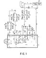
- Fig. 1 is a schematic diagram showing the hydraulic pressure generating apparatus according to one embodiment of the invention, which is applied to an hydraulic pressure control system of such as a steam turbine or gas turbine.
- the hydraulic pressure generating apparatus includes an oil tank 1, a hydraulic oil feed line 4 for feeding hydraulic oil 2 accommodated in the oil tank 1 to an hydraulic pressure control system 3 such as a steam turbine or gas turbine with high pressure, a hydraulic oil return line 5 for returning drain oil from the hydraulic pressure control system 3 to the oil tank 1, and a circulation line 6 for performing purification or cooling by circulating the hydraulic oil 2 of the oil tank 1.
- an hydraulic pressure control system 3 such as a steam turbine or gas turbine with high pressure
- a hydraulic oil return line 5 for returning drain oil from the hydraulic pressure control system 3 to the oil tank 1
- a circulation line 6 for performing purification or cooling by circulating the hydraulic oil 2 of the oil tank 1.
- the oil tank is constituted by a sealed box type container, for example, and has a simple construction which requires no exterior coverage in its periphery.
- a feeding pump 7 for discharging the accommodated hydraulic oil 2 into the hydraulic oil feed line 4 with pressure.
- the feeding pump includes a main oil feeding pump 7a for normal use and an auxiliary oil feeding pump 7b for emergency.
- These main oil feeding pump 7a and auxiliary oil feeding pump 7b are disposed in parallel to the hydraulic oil feed line 4 and in a position upper than a bottom portion within the oil tank 1, and these pumps are also directly coupled to vertical drive shafts 9a and 9b of the motor 8 (8a, 8b) provided on an upper wall of the oil tank, respectively.
- these main oil feeding pump 7a and auxiliary oil feeding pump 7b are adapted to be operable simultaneously or separately by a control unit, which is not shown. Further, the main oil feeding pump 7a and auxiliary oil feeding pump 7b have self-pressure compensators, which are not shown, for stably feeding a required control oil with constant pressure by holding the discharging pressure constant.
- a first circulating pump 10a and a second auxiliary circulating pump 10b are provided in the oil tank as a circulating pump 10 for circulating the accommodated hydraulic oil 2 in the circulation line 6.
- These first circulating pump 10a and the second auxiliary circulating pump 10b are disposed in parallel to the circulation line 6 and adjacently on the lower side of the main oil feeding pump 7a and auxiliary oil feeding pump 7b.
- the first circulating pump 10a is coaxially connected to the drive shaft 9a for rotating the main oil feeding pump 7a and the second auxiliary circulating pump 10b is coaxially connected to the drive shaft 9b for rotating the auxiliary oil feeding pump 7b. That is, the main oil feeding pump 7a and the first circulating pump 10a are of direct-coupled type, which are simultaneously driven by one motor 8a, and on the other hand, the auxiliary oil feeding pump 7b and the second auxiliary circulating pump 10b are also of direct-coupled type, which are simultaneously driven by another motor 8b.
- a heater 11 is provided within the oil tank as direct heating means capable of contacting the hydraulic oil 2 to directly heat the hydraulic oil 2.
- This heater 11 has a structure capable of arbitrarily adjusting the heating temperature by an electric heater, for example, and provided in a range from a location of the side wall of the oil tank 1 to the accommodating height of the hydraulic oil 2 with its heater part inserted into the tank.
- a temperature sensor 12 for sensing temperature of the hydraulic oil 2 is provided within the oil tank 1.
- the heater 11 and the temperature sensor 12 are connected to temperature control means 13, and the temperature of the hydraulic oil 2 within the oil tank 1, which has been sensed by the temperature sensor 12, is regularly input to the temperature control means 13.
- the temperature inside of the tank is compared with the preset temperature by the temperature control means 13 in accordance with the input (signal) from the temperature sensor 12, and the heating temperature of the heater 11 is automatically controlled so as to accord with a target temperature of the hydraulic oil 2.
- a liquid level indicator 14 for monitoring the level of oil within the tank of the hydraulic oil 2 an air breather 15 for keeping the oil tank 1 with atmosphere pressure and maintaining air that contacts the hydraulic oil 2 in a dry state are provided.
- the hydraulic oil feed line 4 is constituted as a pipe line to a hydraulic control system 3 by integrating discharging pipe units 16a and 16b of pump, which are separately guided from the main oil feeding pump 7a and the auxiliary oil feeding pump 7b to the outside of the oil tank 1.
- discharging pipe units 16a and 16b of pump there are also disposed check valves 17a and 17b for back flow prevention of the line are provided, respectively, and relief pipe units 19a and 19b to the oil tank 1, which have relief valves 18a and 18b branching on an upper stream side of those check valves 17a and 17b.
- Oil purifying units 20a and 20b for purifying the hydraulic oil to be fed are provided on an downstream side of the integrated part of the discharging pipe units 16a and 16b of the hydraulic oil feed line 4.
- two sets of oil purifying units 20a and 20b are provided in branch pipe units 21 a and 21 b, by which the hydraulic oil feed line 4 is branched in two, in parallel to each other for normal use and auxiliary use.
- Both of the feed oil purifying units 20a and 20b for normal use and auxiliary use have constructions including first stop valves 22a and 22b, feed oil filters 23a and 23b for oil filtration, and second stop valves 24a and 24b, respectively.
- the first stop valve 22a and the second stop valve 24a of the normal feed oil purifying unit 20a are of normally open type, and, at the time of normal operation, the hydraulic oil 2 is purified by the feed oil filter 23a of the normal feed oil purifying unit 20a.
- the first stop valve 22b and the second stop valve 24b of the auxiliary feed oil purifying unit 20b are of normally closed type, which are opened as occasion demands.
- the first stop valve 22a and the second stop valve 24a of the normal feed oil purifying unit 20a are closed and the first stop valve 22b and the second stop valve 24b of the auxiliary feed oil purifying unit 20b are opened, and the oil is filtered by the feed oil filter 23b of the auxiliary feed oil purifying unit 20b.
- bypass line 25 for bypassing the hydraulic oil 2 to the hydraulic oil return line 5 and returning it to the oil tank.
- this bypass line 25 one or more normally closed bypass valves 26 may be disposed to be opened as occasion demands.
- an accumulator 28 is provided via a normally open stop valve 27 so that the pressure variation of the fed hydraulic oil 2 may be absorbed.
- a drain pan, a drain collecting unit, etc., which are not shown, are provided, and the hydraulic oil return line 5 is provided from such drain collecting unit to the oil tank 1.
- the front end portion of the hydraulic oil return line 5 is inserted into the oil tank at a position lower than an inlet opening of the oil feeding pump 7.
- the circulation line 6 for circulating the control oil within the oil tank 1 is constituted as a pipe which integrates the discharging pump units 29a and 29b of pump separately guided from the first circulating pump 10a and the second circulating pump 10b to the outside of the oil tank 1 and reaches to the oil tank 1 again.
- Check valves 30a and 30b for preventing backflow to the respective circulating pumps 10a and 10b side are provided in the respective discharging pump units 29a and 29b, respectively. Furthermore, circulating oil cooling units 31a and 31 b for cooling the circulating hydraulic oil 2 and circulating oil purifying units 32a and 32b for purifying the circulation oil are provided on the downstream side of the integrated part of the circulation line 6.
- two sets of the circulating oil cooling units 31a and 31 b are provided in branch pipe units 33a and 33b, by which the circulation line 6 is branched in two, in parallel to each other for normal use and auxiliary use, and both the circulating oil cooling units 31a and 31b for normal use and auxiliary use have constructions, sequentially from the upstream side, including first stop valves 34a and 34b, coolers 35a and 35b for cooling the circulating oil, and second stop valves 36a and 36b, respectively.
- the first stop valve 34a and the second stop valve 36a of the normal circulating oil cooling unit 36a are of normally opened type, and, at the time of the normal circulating operation, the circulating oil is cooled by the cooler 35a of this normal circulating oil cooling unit 31a.
- the first stop valve 34b and the second stop valve 36b of the auxiliary circulating oil cooling unit 31b are of normally closed type, which are opened as occasion demands.
- the first stop valve 34a and the second stop valve 36a of the normal circulating oil cooling unit 31a are closed and the first stop valve 34b and the second stop valve 36b of the auxiliary circulating oil cooling unit 31b are opened, and thereby, the circulating oil is cooled by the auxiliary cooler 35b.
- two sets of the circulating oil purifying units 32a and 32b on the downstream side of the circulating oil cooling units 31a and 31 b are provided in parallel branch pipe units 37a and 37b, by which the circulation line 6 is branched in two, for normal use and auxiliary use, and both the circulating oil purifying units 32a and 32b for normal use and auxiliary use have constructions, sequentially from the upstream side, including first stop valves 38a and 38b, circulating oil filters 39a and 39b for circulating oil filtration, and second stop valves 40a and 40b, respectively.
- the first stop valve 38a and the second stop valve 40a of the normal circulating oil purifying unit 32a are of normally opened type, and, at the time of normal operation, the hydraulic oil 2 is purified by the circulating oil filter 39a of the normal circulating oil purifying unit 32a.
- the first stop valve 38b and the second stop valve 40b of the auxiliary circulating oil purifying unit 32b are of normally closed type, which are opened as occasion demands.
- the first stop valve 38a and the second stop valve 40a of the normal circulating oil purifying unit 32a are closed and the first stop valve 38b and the second stop valve 40b of the auxiliary circulating oil purifying unit 32b are opened, and the circulating oil is filtered by the circulating oil filter 39b of the auxiliary circulating oil purifying unit 32b.
- a fatty acid ester oil having organic fatty acid ester as base oil and main component consisting of fatty acid and polyol ester As the flame resistant hydraulic oil 2, a fatty acid ester oil having organic fatty acid ester as base oil and main component consisting of fatty acid and polyol ester.
- This fatty acid ester oil is slightly deteriorated by the direct heating, and when heated to a temperature of about 50°C by the direct heating type heater 11 provided in the oil tank 1, it will be hardly deteriorated.
- this specific gravity of the fatty acid ester is on the order of 0.92 g/cm 3 , for example, assuming the specific gravity is a ratio of the density of the hydraulic oil at temperature of 15°C relative to the density of water at temperature of 4°C, and the fatty acid ester always floats on a level upper than the water mixed into the oil tank 1. Furthermore, it has high oxidation resistance and an activated clay filter etc. is not required.
- This fatty acid ester has viscosity of 20 to 70 cSt (20 to 70 ⁇ 10 -6 m 2 /sec) at 40°C and viscosity index on the order of 180, and the viscosity variation according to the temperature variation is moderate compared to phosphoric ester oil. Its flash point is 240 to 340°C, fire point is 280 to 380°C, spontaneous ignition temperature is about 480°C, and acute toxicity is LD50 > 1.02 ml/N. That is, the fatty acid ester is advantageous in flame resistance and low in toxicity.
- the hydraulic pressure generating apparatus of the described embodiment can set the hydraulic oil 2 within the oil tank 1 to a predetermined temperature (temperature up or down) and can purify it prior to the operation of a steam turbine plant, gas turbine plant, or like, for example, before the activation thereof at the time when the hydraulic pressure control system 3 does not require the hydraulic oil 2.
- the hydraulic oil 2 fed to the hydraulic oil feed line 4 is purified through the feed oil filter 23a of the normal feed oil purifying unit 20a, flown back from the bypass line 25 to the oil tank 1 via the return line to thereby perform the hydraulic oil purifying operation.
- the hydraulic oil 2 circulated into the circulation line 6 by the circulating pump 10 is cooled by the cooler 35a of the normal circulating oil cooling unit 31a, then purified by the circulating oil filter 39a of the normal circulating oil purifying unit 32a, and circulated into the oil tank 1. Then, the temperature of the hydraulic oil 2 within the oil tank 1 is adjusted to the target temperature by the heater 11 controlled by the temperature control means 13 and cooling by the cooler 35a of the circulation line 6.
- the hydraulic oil 2 within the oil tank 1 can be simultaneously purified in both lines of the hydraulic oil feed line 4 and the circulation line 6, the purifying operation is efficiently performed. Furthermore, since the heater 11 is a direct heating type one which directly contacts and heats the hydraulic oil 2 within the oil tank 1, the hydraulic oil 2 within the oil tank 1 can be heated (or cooled) to the target temperature more quickly than a conventional one.
- the heating operation of the hydraulic oil 2 is performed specifically and effectively in a case of a plant which is placed in a cold district.
- the hydraulic pressure generating apparatus is sometimes activated when the hydraulic oil is at extremely low temperature of 0°C (or lower temperature).
- the hydraulic oil 2 within the oil tank 1 can be heated to the target temperature, which is the actual operation temperature, more quickly than the conventional one by setting the temperature sensor 12 so as to sense the hydraulic oil temperature and the heater 11 so as to perform the heating operation until the oil temperature within the control oil tank 1, which is an actual operation temperature, to an optional temperature near 45°C, for example.
- the fatty acid ester oil having only slight deterioration to the heating is used as the hydraulic oil 2, the problem of the hydraulic oil deterioration due to the direct heating will never arise.
- the hydraulic pressure generating apparatus might be activated from the state of low temperature.
- the direct heating type heater 11 is set, when the hydraulic oil temperature within the oil tank 1 becomes low equal to or less than 30°C, for example, so as to perform the heating operation to the optional temperature near 45°C and then stop the operation.
- the control oil can be established in a good state in advance, and, at extremely low temperature, according to the characteristics of the used hydraulic oil 2, the following advantageous effects or functions can be achieved. That is, the direct heating by the direct heating type heater 11 can be performed, the hydraulic oil temperature can be easily raised, and the main oil feeding pump 7a can be activated from the low temperature of 0°C according to the characteristics of the used hydraulic oil 2.
- the bypass valve 26 is closed, the hydraulic oil 2 is discharged from the oil tank 1 into the hydraulic oil feed line 4 by the main oil feeding pump 7a and fed to the hydraulic pressure control system 3 via the normal feed oil filter 23a, and the hydraulic oil 2 is circulated through the operation of the first circulating pump 10a.
- the purification and cooling can be performed by feeding the hydraulic oil 2 accommodated in the oil tank 1 to the hydraulic pressure system 3 with high pressure.
- the drain oil is returned from the hydraulic pressure system to the oil tank 1 via the hydraulic oil return line 5, and the hydraulic oil 2 of the oil tank 1 is circulated through the circulation line 6.
- the direct heating type heater 11 is preliminarily driven in response to the hydraulic oil temperature sensed by the temperature sensor 12 and set so that the hydraulic oil temperature within the oil tank 1 becomes in the order of 45°C to 50°C, for example.
- the circulating pump 10 of the circulation line 6 and the cooler for cooling the circulating oil are activated and set so as to perform the cooling until the hydraulic oil temperature becomes 40 to 45°C and then stop the operation of the oil cooler so as not to become a further low temperature.
- the hydraulic oil temperature within the oil tank 1 is regularly controlled at nearly 45°C, for example, and according to such hydraulic oil feeding operation, the temperature control of the hydraulic oil 2 can be easily, quickly, and stably performed through the heating of the heater 11.
- the location of the circulating pump 10 which is driven coaxially with the main oil feeding pump 7a permits the oil to be continuously cooled and filtered in the special circulating line 6, thus the temperature and the cleanliness of oil being stably controlled.
- the hydraulic oil can be stably fed, while maintaining characteristics of the flame resistance substantially equal to conventional.
- the auxiliary oil feeding pump 7b is operated simultaneously with the main oil feeding pump 7a or switched to be operated.
- the respective normally closed stop valves 22b and 24b of the auxiliary feed oil purifying unit 20b in the hydraulic oil feed line 4 are opened, while the respective normally opened stop valves 22a and 24a of the normal feed oil purifying unit 20a being closed according to the necessity of repair etc.
- the second circulating pump 10b directly coupled thereto is also operated, and the respective valves of the auxiliary circulating oil cooling unit 35b and the auxiliary circulating oil purifying unit 32b are also opened.
- the respective valves 34a, 36a, 38a, and 40a of the normal circulating oil cooling unit 31a and the normal circulating oil purifying unit 32a are closed as occasion demands, and the amount of the hydraulic oil is increased or the circulation line 6 is switched.
- the respective pump operations are flexibly performed, and the stable hydraulic feeding and circulation are performed in a constantly suitable state, thus stably controlling the hydraulic pressure.
- main oil feeding pump 7a and the auxiliary oil feeding pump 7b have self-pressure compensators and can hold the discharging pressure constant and feed the stable and required control oil at constant hydraulic pressure. Further, the pressure variation of the hydraulic oil feed line 4 is absorbed by the accumulator 28.
- the operation efficiency of the hydraulic pressure generating apparatus can be largely improved, thus being advantageous.
- the feed oil purifying units 20a and 20b for normal use and emergency use are provided in the parallel branch pipe units 21a and 21b formed by dividing the hydraulic line 4, and both the circulating oil purifying units 20a and 20b are respectively constructed by including the first stop valves 22a and 22b, the feed oil filters 23a and 23b, and the second stop valves 24a and 24b sequentially from the upstream side.
- two sets of circulating oil cooling units 31a and 31b are provided in branch pipe units 33a and 33b, by which the circulation line 6 is branched in two, in parallel to each other for normal use and auxiliary use, and both the circulating oil cooling units 31a and 31 b for normal use and auxiliary use have constructions, sequentially from the upstream side, including first stop valves 34a and 34b, cooler 35a and 35b for cooling circulating oil, and second stop valves 36a and 36b, respectively.
- two sets of circulating oil filters 39a and 39b are provided in parallel branch pipe units 37a and 37b, by which the circulation line 6 is branched in two, for normal use and auxiliary use, and constructed, sequentially from the upstream side, by including the first stop valves 38a and 38b, the coolers 39a and 39b for circulating oil filtration, and second stop valves 40a and 40b.
- the filter element can be exchanged and inspected by closing the stop valves disposed on upstream and downstream sides of either one of the branch pipe units 21a and 21b and opening the stop valves disposed on upstream and downstream sides of the other of the branch pipe units 21a and 21b without being affected by the hydraulic pressure of the respective lines. Therefore, at both times of activation and normal operation, the maintenance can be performed without stopping the hydraulic oil feeding.
- the hydraulic oil 2 in the tank 1 can be circulated via the hydraulic oil feed line 4, the bypass line 25, and the hydraulic oil return line 5 by opening the normally closed bypass valve 26 of the bypass line. Therefore, for example, when the feed oil filter 23a of one parallel branch 20a is exchanged, the hydraulic oil purifying operation can be performed in parallel by passing the hydraulic oil 2 through the feed oil filter 23b of the other parallel branch 20b, and by carrying out the purification during the halt of the apparatus, the hydraulic oil 2 can be purified in a good condition at the time of when repair and inspection made by performing the purification of the hydraulic oil 2 during the halt of the apparatus.
- the handling of the hydraulic oil 2 itself becomes easy and it can be easily wasted by an easy disposal treatment.
- the handling of the exchanging device and maintenance tools for the hydraulic oil 2 and the handling of the waste disposal become easy, and the maintenance can be largely improved. Further, the cost of hydraulic oil can be reduced compared to phosphoric ester oil.
- hydraulic oil 2 of the described embodiment can be easily used as criterion of judgment when exchanging to new oil by checking the deterioration condition from the viscosity, the total acid number, etc.
- the fatty acid ester oil as the hydraulic oil 2, there may be achieved extremely good wear resistance against the hydraulic pressure devices such as the main oil feeding pump 7a and the auxiliary oil feeding pump, and sealing and packing materials other than fluorine rubber such as nitrile rubber, which is considered to be difficult to used for the phosphoric esters hydraulic oil 2, may be used.
- the maintenance can also be improved.
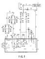
- Fig. 2 shows a hydraulic pressure generating apparatus according to another embodiment of the present invention.
- the hydraulic pressure generating apparatus of this embodiment differs from the embodiment described above with reference to Fig. 1 in that the pipe construction such as the discharging pipe from the oil feeding pump 7 and the feed oil purifying units 20a and 20b in the hydraulic oil feed line 4 are constituted by independent pipes, respectively, and check valves 41a and 41b for preventing backflow to the pump side are provided between the feed oil filters 23a and 23b and the second stop on the downstream side thereof, respectively.
- the other construction is the substantially the same as that in the first embodiment, and like reference numerals are applied to elements or members corresponding to those shown in Fig. 1 and the description thereof will be omitted herein.
- the first circulating pump 10a and the second circulating pump 10b are constructed by directly coupled to the main oil feeding pump 7a and the auxiliary oil feeding pump 7b.
- the first circulating pump 10a and the second circulating pump 10b may be constructed so as to be driven by a motor different from the main oil feeding pump 7a and the auxiliary oil feeding pump 7b.
- coolers 35a and 35b shown in the respective embodiments or coolers equivalent thereto are relocated or disposed in parallel in the hydraulic oil return line 5, it is advantageous that further cooling effects may be obtainable by directly cooling the drain oil returned at high temperature.
- the circulating line 6 is unnecessary to be provided.
- stop valves for example, required number of stop valves, relief valves, check valves, filters, etc. are provided in the hydraulic oil feed line 4, the circulating line 6, the bypass line 25 and the like.
- the present invention functions by providing at minimum one stop valve, relief valve, check valve or filter, respectively, and the changes there of in location numbers may be optionally made.
Landscapes
- Engineering & Computer Science (AREA)
- Physics & Mathematics (AREA)
- Fluid Mechanics (AREA)
- Mechanical Engineering (AREA)
- General Engineering & Computer Science (AREA)
- Chemical & Material Sciences (AREA)
- Analytical Chemistry (AREA)
- Fluid-Pressure Circuits (AREA)
- Details Of Reciprocating Pumps (AREA)
- Supply Devices, Intensifiers, Converters, And Telemotors (AREA)
Abstract
Description
Claims (15)
- A hydraulic pressure generating apparatus comprising:wherein the hydraulic oil is flame resistant hydraulic oil which is hardly deteriorated by direct heating, and the flame resistant hydraulic oil is heated by heating means disposed in the oil tank.a hydraulic oil feed line for feeding hydraulic oil with high pressure from an oil tank to a hydraulic pressure control system of a generator by an oil feeding pump unit;a hydraulic oil return line for returning drain oil from the hydraulic pressure control system to the oil tank; anda circulation line for circulating and purifying the hydraulic oil of the oil tank by a circulating pump unit,
- A hydraulic pressure generating apparatus comprising:wherein said hydraulic oil is flame resistant hydraulic oil having specific gravity of less than 1.0, and the oil feeding pump is of in-tank installation type and disposed on a side upper than a bottom portion in the oil tank.a hydraulic oil feed line for feeding hydraulic oil with high pressure from an oil tank to a hydraulic pressure control system of a generator by an oil feeding pump unit;a hydraulic oil return line for returning drain oil from the hydraulic pressure control system to the oil tank; anda circulation line for circulating and purifying the hydraulic oil of the oil tank by a circulating pump unit,
- A hydraulic pressure generating apparatus comprising:wherein said control oil is flame resistant hydraulic oil having high oxidation resistance, and the circulation line is of activated clay filter dispensable type.a hydraulic oil feed line for feeding hydraulic oil with high pressure from an oil tank to a hydraulic pressure control system of a generator by an oil feeding pump unit;a hydraulic oil return line for returning drain oil from the hydraulic pressure control system to the oil tank; anda circulation line for circulating and purifying the hydraulic oil of the oil tank by a circulating pump unit,
- A hydraulic pressure generating apparatus comprising:wherein said control oil is flame resistant hydraulic oil having low toxicity.a hydraulic oil feed line for feeding hydraulic oil with high pressure from an oil tank to a hydraulic pressure control system of a generator by an oil feeding pump unit;a hydraulic oil return line for returning drain oil from the hydraulic pressure control system to the oil tank; anda circulation line for circulating and purifying the hydraulic oil of the oil tank by a circulating pump unit,
- A hydraulic pressure generating apparatus according to any one of claims 1 to 4, wherein said flame resistant hydraulic oil is fatty acid ester oil.
- A hydraulic pressure generating apparatus according to any one of claims 1 to 4, wherein said flame resistant hydraulic oil has a feeding pressure set to be equal to or more than 6.8 MPa.
- A hydraulic pressure generating apparatus according to any one of claims 1 to 4, wherein said oil feeding pump unit includes a main oil feeding pump and an auxiliary oil feeding pump in parallel to the hydraulic oil feed line, and said circulating pump unit includes a first circulating pump and a second circulating pump in parallel to the circulation line, said main oil feeding pump and said first circulating pump being of direct-coupled type, which are simultaneously driven by one motor, and said auxiliary oil feeding pump and said second circulating pump being of direct-coupled type, which are simultaneously driven by another motor.
- A hydraulic pressure generating apparatus according to any one of claims 1 to 4, wherein said hydraulic oil feed line is provided with at least one or more feed oil filters, check valves, and stop valves.
- A hydraulic pressure generating apparatus according to any one of claims 1 to 4, wherein said circulation line is provided with at least one or more oil coolers, circulating oil filters, check valves, and stop valves.
- A hydraulic pressure generating apparatus according to any one of claims 1 to 4, wherein said hydraulic oil feed line and said hydraulic oil return line are connected by a bypass line, and at least one or more stop valves are arranged to the bypass line.
- A hydraulic pressure generating apparatus according to any one of claims 1 to 4, further comprising a temperature sensor for sensing temperature in the oil tank, and temperature control means for controlling heating means disposed in the oil tank in accordance with the temperature in the tank sensed by the temperature sensor.
- A hydraulic pressure generating apparatus comprising:wherein said flame resistant hydraulic oil is fatty acid ester oil which is fed at a feeding pressure set to be equal to or more than 6.8 MPa.a hydraulic oil feed line for feeding hydraulic oil with high pressure from an oil tank to a hydraulic pressure control system of a generator by an oil feeding pump unit;a hydraulic oil return line for returning drain oil from the hydraulic pressure control system to the oil tank; anda circulation line for circulating and purifying the hydraulic oil of the oil tank by a circulating pump unit,
- A hydraulic pressure generating apparatus comprising:a hydraulic oil feed line for feeding hydraulic oil with high pressure from an oil tank to a hydraulic pressure control system of a generator by an oil feeding pump unit including a main oil feeding pump and an auxiliary oil feeding pump in parallel to the hydraulic oil feed line, said hydraulic oil feed line being provided with at least one or more feed oil filters, check valves, and stop valves;a hydraulic oil return line for returning drain oil from the hydraulic pressure control system to the oil tank; anda circulation line for circulating and purifying the hydraulic oil of the oil tank by a circulating pump unit including a first circulating pump and a second circulating pump in parallel to the circulation line, said circulation line being provided with at least one or more oil coolers, circulating oil filters, check valves, and stop valves,said main oil feeding pump and said first circulating pump being of direct-coupled type, which are simultaneously driven by one motor, and said auxiliary oil feeding pump and said second circulating pump being of direct-coupled type, which are simultaneously driven by another motor, andsaid hydraulic oil feed line and said hydraulic oil return line being connected by a bypass line, and at least one or more stop valves are arranged to the bypass line.
- A hydraulic pressure generating apparatus according to claim 13, wherein said flame resistant hydraulic oil is fatty acid ester oil which is fed at a feeding pressure set to be equal to or more than 6.8 MPa.
- A hydraulic pressure generating apparatus according to claim 13, further comprising a temperature sensor for sensing temperature in the oil tank, and temperature control means for controlling heating means disposed in the oil tank in accordance with the temperature in the tank sensed by the temperature sensor.
Applications Claiming Priority (2)
| Application Number | Priority Date | Filing Date | Title |
|---|---|---|---|
| JP2002350409 | 2002-12-02 | ||
| JP2002350409A JP2004183539A (en) | 2002-12-02 | 2002-12-02 | Hydraulic generator |
Publications (3)
| Publication Number | Publication Date |
|---|---|
| EP1426627A2 true EP1426627A2 (en) | 2004-06-09 |
| EP1426627A3 EP1426627A3 (en) | 2005-09-21 |
| EP1426627B1 EP1426627B1 (en) | 2011-02-23 |
Family
ID=32310688
Family Applications (1)
| Application Number | Title | Priority Date | Filing Date |
|---|---|---|---|
| EP20030027286 Expired - Lifetime EP1426627B1 (en) | 2002-12-02 | 2003-11-28 | Hydraulic pressure-generating apparatus |
Country Status (5)
| Country | Link |
|---|---|
| US (1) | US6964162B2 (en) |
| EP (1) | EP1426627B1 (en) |
| JP (1) | JP2004183539A (en) |
| CN (1) | CN1306172C (en) |
| DE (1) | DE60336107D1 (en) |
Cited By (2)
| Publication number | Priority date | Publication date | Assignee | Title |
|---|---|---|---|---|
| AT15555U1 (en) * | 2016-01-13 | 2017-12-15 | Hp3 Real Gmbh | Hydraulics for a track construction machine with a fluid tank |
| DE102009035810B4 (en) | 2009-08-01 | 2019-06-19 | Hydac Systems & Services Gmbh | Device for supplying at least one hydraulic consumer of a military vehicle |
Families Citing this family (28)
| Publication number | Priority date | Publication date | Assignee | Title |
|---|---|---|---|---|
| CA2585129A1 (en) * | 2004-10-25 | 2006-05-04 | Porous Media Corporation | Membrane-based reservoir dryer |
| US8038412B2 (en) | 2007-06-06 | 2011-10-18 | Hamilton Sundstrand Corporation | Temperature management for electric motor driven pump |
| US8387354B2 (en) * | 2010-09-14 | 2013-03-05 | General Electric Company | Oil varnish mitigation systems |
| JP5683895B2 (en) * | 2010-10-14 | 2015-03-11 | 株式会社東芝 | Steam valve device |
| CN102213252B (en) * | 2011-06-15 | 2015-08-12 | 衡阳华菱钢管有限公司 | Online dispersing hydraulic station oil tank centralized oil supplementing system and oil supplement method |
| CN102954067A (en) * | 2011-08-26 | 2013-03-06 | 镇江市科能电力设备有限公司 | Double-cartridge filter |
| CN102635603A (en) * | 2012-05-02 | 2012-08-15 | 济南东测试验机技术有限公司 | Oil source device for hydraulic system |
| US10280906B2 (en) | 2016-06-07 | 2019-05-07 | Kubota Corporation | Hydraulic system for work machine |
| CN106704310B (en) * | 2017-02-08 | 2019-08-06 | 徐州工程学院 | Parallel double overload protection multi-cavity oil pressure constant power heating system device and method |
| CN109401829A (en) * | 2017-08-17 | 2019-03-01 | 绍兴齐英膜科技有限公司 | A kind of device and technique of hydraulic oil deep dehydration |
| US20190183038A1 (en) * | 2017-12-15 | 2019-06-20 | Cnh Industrial Canada, Ltd. | System for controlling product treatment flow through distribution lines |
| GB2569783A (en) * | 2017-12-15 | 2019-07-03 | Airbus Operations Ltd | Hydraulic system characteristics |
| CN109611417B (en) * | 2018-12-13 | 2024-11-15 | 中车长春轨道客车股份有限公司 | Multi-stage circulation filtration hydraulic system |
| CN109798283A (en) * | 2019-01-21 | 2019-05-24 | 江苏大学 | One kind remotely controlling more relay protective scheme function central pumping stations |
| AU2019455088A1 (en) | 2019-06-26 | 2021-11-11 | Graco Minnesota Inc. | Heated lubricant pump |
| CN110469562A (en) * | 2019-09-16 | 2019-11-19 | 中国铁建重工集团股份有限公司 | A kind of underwater hydraulic compensation device and hydraulic system |
| CN110588935A (en) * | 2019-09-23 | 2019-12-20 | 中国船舶重工集团公司第七0四研究所 | Hydraulic system for icebreaker controllable pitch propeller |
| CN111536100B (en) * | 2020-04-30 | 2022-09-06 | 肇庆学院 | A temperature control system and temperature control method for a high-acceleration test bench for hydraulic components |
| CN112503378B (en) * | 2020-11-30 | 2024-08-02 | 沪东重机有限公司 | Lubricating oil tank with independent hydraulic oil control system for diesel engine |
| CN112833068B (en) * | 2020-12-16 | 2023-07-28 | 中国南方电网有限责任公司超高压输电公司曲靖局 | Integrated movable oil filtering and injecting equipment for hydraulic mechanism |
| DE202021105582U1 (en) * | 2021-10-14 | 2021-10-25 | Emg Automation Gmbh | Electro-hydraulic actuation device with integrated electrical functional elements |
| CN115142860A (en) * | 2022-05-20 | 2022-10-04 | 中铁十五局集团有限公司 | A kind of shield machine water circulation system and water circulation method |
| CN115585166A (en) * | 2022-09-30 | 2023-01-10 | 华能上海燃机发电有限责任公司 | A method and device for improving oil filtration efficiency of unit gas turbine control oil |
| CN115949884A (en) * | 2023-01-03 | 2023-04-11 | 中冶赛迪技术研究中心有限公司 | a refueling system |
| US20250034844A1 (en) * | 2023-07-26 | 2025-01-30 | Great Plains Manufacturing, Inc. | Work machine with multiple hydraulic tanks |
| CN117505574B (en) * | 2023-12-11 | 2025-11-14 | 佛山市恒力泰机械有限公司 | An integrated pump station for extrusion equipment |
| CN118847016B (en) * | 2024-09-26 | 2024-12-24 | 西安热工研究院有限公司 | A phosphate ester fire-resistant oil micro-oxidation system and oxidation monitoring method |
| CN120334282A (en) * | 2025-06-18 | 2025-07-18 | 西安热工研究院有限公司 | A dynamic measurement system and method for phosphate ester fire-resistant oil performance |
Citations (1)
| Publication number | Priority date | Publication date | Assignee | Title |
|---|---|---|---|---|
| JPH11351209A (en) | 1998-06-09 | 1999-12-24 | Toshiba Eng Co Ltd | High pressure ehc control oil device |
Family Cites Families (3)
| Publication number | Priority date | Publication date | Assignee | Title |
|---|---|---|---|---|
| FR1603503A (en) | 1968-10-10 | 1971-05-03 | ||
| US5600954A (en) * | 1994-10-05 | 1997-02-11 | New Holland North America, Inc. | Tractor hydraulic reservoir heating element |
| JP3586568B2 (en) | 1998-07-22 | 2004-11-10 | 三菱重工業株式会社 | Hydraulic control device |
-
2002
- 2002-12-02 JP JP2002350409A patent/JP2004183539A/en active Pending
-
2003
- 2003-11-26 US US10/721,545 patent/US6964162B2/en not_active Expired - Lifetime
- 2003-11-28 EP EP20030027286 patent/EP1426627B1/en not_active Expired - Lifetime
- 2003-11-28 DE DE60336107T patent/DE60336107D1/en not_active Expired - Lifetime
- 2003-12-02 CN CNB2003101187534A patent/CN1306172C/en not_active Expired - Lifetime
Patent Citations (1)
| Publication number | Priority date | Publication date | Assignee | Title |
|---|---|---|---|---|
| JPH11351209A (en) | 1998-06-09 | 1999-12-24 | Toshiba Eng Co Ltd | High pressure ehc control oil device |
Cited By (2)
| Publication number | Priority date | Publication date | Assignee | Title |
|---|---|---|---|---|
| DE102009035810B4 (en) | 2009-08-01 | 2019-06-19 | Hydac Systems & Services Gmbh | Device for supplying at least one hydraulic consumer of a military vehicle |
| AT15555U1 (en) * | 2016-01-13 | 2017-12-15 | Hp3 Real Gmbh | Hydraulics for a track construction machine with a fluid tank |
Also Published As
| Publication number | Publication date |
|---|---|
| JP2004183539A (en) | 2004-07-02 |
| EP1426627A3 (en) | 2005-09-21 |
| CN1512080A (en) | 2004-07-14 |
| US20040103657A1 (en) | 2004-06-03 |
| EP1426627B1 (en) | 2011-02-23 |
| US6964162B2 (en) | 2005-11-15 |
| DE60336107D1 (en) | 2011-04-07 |
| CN1306172C (en) | 2007-03-21 |
Similar Documents
| Publication | Publication Date | Title |
|---|---|---|
| US6964162B2 (en) | Hydraulic pressure generating apparatus | |
| US4809745A (en) | Oil container for the supply of hydraulic power circuits | |
| US5897297A (en) | Washing objects and recovering contaminants with optimized pump control | |
| CN202052738U (en) | Hydraulic pipeline cleaner | |
| JP2004183539A5 (en) | ||
| CN103967850A (en) | Oil tank assembly for hydraulic system and use method thereof | |
| US9999843B2 (en) | Offline filtration device and method | |
| FR2468485A1 (en) | Heating control for hydraulic servo circuit - has variable return flow over flow restriction | |
| CN1121580C (en) | A closed liquid circulation system and expansion control method thereof | |
| EP1485654A1 (en) | Heating system, method for operating a heating system and use thereof | |
| KR101723383B1 (en) | Temperature control system of oil tank | |
| US20030015313A1 (en) | Apparatus and method for cleaning a shell-type cooler in situ and cleaning liquid for use therewith | |
| US12209488B2 (en) | Fracturing apparatus | |
| CN2739366Y (en) | Lubricating oil on-line purifying device | |
| CN102840315A (en) | Coal mill gear case lubricating and cooling washing method | |
| EP2009342A1 (en) | Circulation lubrication system | |
| CN107281792A (en) | A kind of heating and ventilating pipeline dirt separator | |
| JP3318810B2 (en) | Plumbing cleaning system | |
| CN210715385U (en) | Accurate control device for oil temperature in hydraulic test system | |
| CN222879792U (en) | A methanol fuel supply system for a ship dual-fuel generator | |
| JP2734190B2 (en) | Method and apparatus for heating oil for rotating machinery | |
| EP3265725B1 (en) | Device and method for the cogeneration of electrical energy and thermal energy | |
| AU2011375717A1 (en) | Method for draining thermal oil in a thermosolar plant, and corresponding auxiliary installation for carrying out said method | |
| KR101646006B1 (en) | An Apparatus for Clearing with a Structure of Pressure Vessel | |
| KR102504898B1 (en) | Car heater blockage repair device |
Legal Events
| Date | Code | Title | Description |
|---|---|---|---|
| PUAI | Public reference made under article 153(3) epc to a published international application that has entered the european phase |
Free format text: ORIGINAL CODE: 0009012 |
|
| 17P | Request for examination filed |
Effective date: 20031128 |
|
| AK | Designated contracting states |
Kind code of ref document: A2 Designated state(s): AT BE BG CH CY CZ DE DK EE ES FI FR GB GR HU IE IT LI LU MC NL PT RO SE SI SK TR |
|
| AX | Request for extension of the european patent |
Extension state: AL LT LV MK |
|
| PUAL | Search report despatched |
Free format text: ORIGINAL CODE: 0009013 |
|
| AK | Designated contracting states |
Kind code of ref document: A3 Designated state(s): AT BE BG CH CY CZ DE DK EE ES FI FR GB GR HU IE IT LI LU MC NL PT RO SE SI SK TR |
|
| AX | Request for extension of the european patent |
Extension state: AL LT LV MK |
|
| AKX | Designation fees paid |
Designated state(s): DE FR GB |
|
| 17Q | First examination report despatched |
Effective date: 20070213 |
|
| GRAP | Despatch of communication of intention to grant a patent |
Free format text: ORIGINAL CODE: EPIDOSNIGR1 |
|
| GRAS | Grant fee paid |
Free format text: ORIGINAL CODE: EPIDOSNIGR3 |
|
| GRAA | (expected) grant |
Free format text: ORIGINAL CODE: 0009210 |
|
| AK | Designated contracting states |
Kind code of ref document: B1 Designated state(s): DE FR GB |
|
| REG | Reference to a national code |
Ref country code: GB Ref legal event code: FG4D |
|
| REF | Corresponds to: |
Ref document number: 60336107 Country of ref document: DE Date of ref document: 20110407 Kind code of ref document: P |
|
| REG | Reference to a national code |
Ref country code: DE Ref legal event code: R096 Ref document number: 60336107 Country of ref document: DE Effective date: 20110407 |
|
| PLBE | No opposition filed within time limit |
Free format text: ORIGINAL CODE: 0009261 |
|
| STAA | Information on the status of an ep patent application or granted ep patent |
Free format text: STATUS: NO OPPOSITION FILED WITHIN TIME LIMIT |
|
| 26N | No opposition filed |
Effective date: 20111124 |
|
| REG | Reference to a national code |
Ref country code: DE Ref legal event code: R097 Ref document number: 60336107 Country of ref document: DE Effective date: 20111124 |
|
| REG | Reference to a national code |
Ref country code: FR Ref legal event code: PLFP Year of fee payment: 13 |
|
| REG | Reference to a national code |
Ref country code: FR Ref legal event code: PLFP Year of fee payment: 14 |
|
| REG | Reference to a national code |
Ref country code: FR Ref legal event code: PLFP Year of fee payment: 15 |
|
| REG | Reference to a national code |
Ref country code: FR Ref legal event code: PLFP Year of fee payment: 16 |
|
| PGFP | Annual fee paid to national office [announced via postgrant information from national office to epo] |
Ref country code: FR Payment date: 20221010 Year of fee payment: 20 |
|
| PGFP | Annual fee paid to national office [announced via postgrant information from national office to epo] |
Ref country code: GB Payment date: 20221006 Year of fee payment: 20 Ref country code: DE Payment date: 20220621 Year of fee payment: 20 |
|
| REG | Reference to a national code |
Ref country code: DE Ref legal event code: R071 Ref document number: 60336107 Country of ref document: DE |
|
| REG | Reference to a national code |
Ref country code: GB Ref legal event code: PE20 Expiry date: 20231127 |
|
| PG25 | Lapsed in a contracting state [announced via postgrant information from national office to epo] |
Ref country code: GB Free format text: LAPSE BECAUSE OF EXPIRATION OF PROTECTION Effective date: 20231127 |
|
| PG25 | Lapsed in a contracting state [announced via postgrant information from national office to epo] |
Ref country code: GB Free format text: LAPSE BECAUSE OF EXPIRATION OF PROTECTION Effective date: 20231127 |