EP1426564B1 - Method and device for controlling the output of a combined heat and power plant - Google Patents
Method and device for controlling the output of a combined heat and power plant Download PDFInfo
- Publication number
- EP1426564B1 EP1426564B1 EP02026036A EP02026036A EP1426564B1 EP 1426564 B1 EP1426564 B1 EP 1426564B1 EP 02026036 A EP02026036 A EP 02026036A EP 02026036 A EP02026036 A EP 02026036A EP 1426564 B1 EP1426564 B1 EP 1426564B1
- Authority
- EP
- European Patent Office
- Prior art keywords
- heating
- steam
- heated
- medium
- power station
- Prior art date
- Legal status (The legal status is an assumption and is not a legal conclusion. Google has not performed a legal analysis and makes no representation as to the accuracy of the status listed.)
- Expired - Lifetime
Links
Images

Classifications
-
- F—MECHANICAL ENGINEERING; LIGHTING; HEATING; WEAPONS; BLASTING
- F24—HEATING; RANGES; VENTILATING
- F24D—DOMESTIC- OR SPACE-HEATING SYSTEMS, e.g. CENTRAL HEATING SYSTEMS; DOMESTIC HOT-WATER SUPPLY SYSTEMS; ELEMENTS OR COMPONENTS THEREFOR
- F24D10/00—District heating systems
-
- F—MECHANICAL ENGINEERING; LIGHTING; HEATING; WEAPONS; BLASTING
- F01—MACHINES OR ENGINES IN GENERAL; ENGINE PLANTS IN GENERAL; STEAM ENGINES
- F01K—STEAM ENGINE PLANTS; STEAM ACCUMULATORS; ENGINE PLANTS NOT OTHERWISE PROVIDED FOR; ENGINES USING SPECIAL WORKING FLUIDS OR CYCLES
- F01K17/00—Using steam or condensate extracted or exhausted from steam engine plant
- F01K17/02—Using steam or condensate extracted or exhausted from steam engine plant for heating purposes, e.g. industrial, domestic
- F01K17/025—Using steam or condensate extracted or exhausted from steam engine plant for heating purposes, e.g. industrial, domestic in combination with at least one gas turbine, e.g. a combustion gas turbine
-
- F—MECHANICAL ENGINEERING; LIGHTING; HEATING; WEAPONS; BLASTING
- F01—MACHINES OR ENGINES IN GENERAL; ENGINE PLANTS IN GENERAL; STEAM ENGINES
- F01K—STEAM ENGINE PLANTS; STEAM ACCUMULATORS; ENGINE PLANTS NOT OTHERWISE PROVIDED FOR; ENGINES USING SPECIAL WORKING FLUIDS OR CYCLES
- F01K23/00—Plants characterised by more than one engine delivering power external to the plant, the engines being driven by different fluids
- F01K23/02—Plants characterised by more than one engine delivering power external to the plant, the engines being driven by different fluids the engine cycles being thermally coupled
- F01K23/06—Plants characterised by more than one engine delivering power external to the plant, the engines being driven by different fluids the engine cycles being thermally coupled combustion heat from one cycle heating the fluid in another cycle
- F01K23/10—Plants characterised by more than one engine delivering power external to the plant, the engines being driven by different fluids the engine cycles being thermally coupled combustion heat from one cycle heating the fluid in another cycle with exhaust fluid of one cycle heating the fluid in another cycle
- F01K23/101—Regulating means specially adapted therefor
-
- F—MECHANICAL ENGINEERING; LIGHTING; HEATING; WEAPONS; BLASTING
- F24—HEATING; RANGES; VENTILATING
- F24D—DOMESTIC- OR SPACE-HEATING SYSTEMS, e.g. CENTRAL HEATING SYSTEMS; DOMESTIC HOT-WATER SUPPLY SYSTEMS; ELEMENTS OR COMPONENTS THEREFOR
- F24D18/00—Small-scale combined heat and power [CHP] generation systems specially adapted for domestic heating, space heating or domestic hot-water supply
-
- F—MECHANICAL ENGINEERING; LIGHTING; HEATING; WEAPONS; BLASTING
- F05—INDEXING SCHEMES RELATING TO ENGINES OR PUMPS IN VARIOUS SUBCLASSES OF CLASSES F01-F04
- F05B—INDEXING SCHEME RELATING TO WIND, SPRING, WEIGHT, INERTIA OR LIKE MOTORS, TO MACHINES OR ENGINES FOR LIQUIDS COVERED BY SUBCLASSES F03B, F03D AND F03G
- F05B2220/00—Application
- F05B2220/60—Application making use of surplus or waste energy
-
- F—MECHANICAL ENGINEERING; LIGHTING; HEATING; WEAPONS; BLASTING
- F24—HEATING; RANGES; VENTILATING
- F24D—DOMESTIC- OR SPACE-HEATING SYSTEMS, e.g. CENTRAL HEATING SYSTEMS; DOMESTIC HOT-WATER SUPPLY SYSTEMS; ELEMENTS OR COMPONENTS THEREFOR
- F24D2101/00—Electric generators of small-scale CHP systems
- F24D2101/10—Gas turbines; Steam engines or steam turbines; Water turbines, e.g. located in water pipes
-
- F—MECHANICAL ENGINEERING; LIGHTING; HEATING; WEAPONS; BLASTING
- F24—HEATING; RANGES; VENTILATING
- F24D—DOMESTIC- OR SPACE-HEATING SYSTEMS, e.g. CENTRAL HEATING SYSTEMS; DOMESTIC HOT-WATER SUPPLY SYSTEMS; ELEMENTS OR COMPONENTS THEREFOR
- F24D2103/00—Thermal aspects of small-scale CHP systems
- F24D2103/10—Small-scale CHP systems characterised by their heat recovery units
- F24D2103/13—Small-scale CHP systems characterised by their heat recovery units characterised by their heat exchangers
-
- Y—GENERAL TAGGING OF NEW TECHNOLOGICAL DEVELOPMENTS; GENERAL TAGGING OF CROSS-SECTIONAL TECHNOLOGIES SPANNING OVER SEVERAL SECTIONS OF THE IPC; TECHNICAL SUBJECTS COVERED BY FORMER USPC CROSS-REFERENCE ART COLLECTIONS [XRACs] AND DIGESTS
- Y02—TECHNOLOGIES OR APPLICATIONS FOR MITIGATION OR ADAPTATION AGAINST CLIMATE CHANGE
- Y02B—CLIMATE CHANGE MITIGATION TECHNOLOGIES RELATED TO BUILDINGS, e.g. HOUSING, HOUSE APPLIANCES OR RELATED END-USER APPLICATIONS
- Y02B30/00—Energy efficient heating, ventilation or air conditioning [HVAC]
- Y02B30/17—District heating
-
- Y—GENERAL TAGGING OF NEW TECHNOLOGICAL DEVELOPMENTS; GENERAL TAGGING OF CROSS-SECTIONAL TECHNOLOGIES SPANNING OVER SEVERAL SECTIONS OF THE IPC; TECHNICAL SUBJECTS COVERED BY FORMER USPC CROSS-REFERENCE ART COLLECTIONS [XRACs] AND DIGESTS
- Y02—TECHNOLOGIES OR APPLICATIONS FOR MITIGATION OR ADAPTATION AGAINST CLIMATE CHANGE
- Y02E—REDUCTION OF GREENHOUSE GAS [GHG] EMISSIONS, RELATED TO ENERGY GENERATION, TRANSMISSION OR DISTRIBUTION
- Y02E20/00—Combustion technologies with mitigation potential
- Y02E20/14—Combined heat and power generation [CHP]
-
- Y—GENERAL TAGGING OF NEW TECHNOLOGICAL DEVELOPMENTS; GENERAL TAGGING OF CROSS-SECTIONAL TECHNOLOGIES SPANNING OVER SEVERAL SECTIONS OF THE IPC; TECHNICAL SUBJECTS COVERED BY FORMER USPC CROSS-REFERENCE ART COLLECTIONS [XRACs] AND DIGESTS
- Y02—TECHNOLOGIES OR APPLICATIONS FOR MITIGATION OR ADAPTATION AGAINST CLIMATE CHANGE
- Y02E—REDUCTION OF GREENHOUSE GAS [GHG] EMISSIONS, RELATED TO ENERGY GENERATION, TRANSMISSION OR DISTRIBUTION
- Y02E20/00—Combustion technologies with mitigation potential
- Y02E20/16—Combined cycle power plant [CCPP], or combined cycle gas turbine [CCGT]
-
- Y—GENERAL TAGGING OF NEW TECHNOLOGICAL DEVELOPMENTS; GENERAL TAGGING OF CROSS-SECTIONAL TECHNOLOGIES SPANNING OVER SEVERAL SECTIONS OF THE IPC; TECHNICAL SUBJECTS COVERED BY FORMER USPC CROSS-REFERENCE ART COLLECTIONS [XRACs] AND DIGESTS
- Y02—TECHNOLOGIES OR APPLICATIONS FOR MITIGATION OR ADAPTATION AGAINST CLIMATE CHANGE
- Y02P—CLIMATE CHANGE MITIGATION TECHNOLOGIES IN THE PRODUCTION OR PROCESSING OF GOODS
- Y02P80/00—Climate change mitigation technologies for sector-wide applications
- Y02P80/10—Efficient use of energy, e.g. using compressed air or pressurized fluid as energy carrier
- Y02P80/14—District level solutions, i.e. local energy networks
-
- Y—GENERAL TAGGING OF NEW TECHNOLOGICAL DEVELOPMENTS; GENERAL TAGGING OF CROSS-SECTIONAL TECHNOLOGIES SPANNING OVER SEVERAL SECTIONS OF THE IPC; TECHNICAL SUBJECTS COVERED BY FORMER USPC CROSS-REFERENCE ART COLLECTIONS [XRACs] AND DIGESTS
- Y02—TECHNOLOGIES OR APPLICATIONS FOR MITIGATION OR ADAPTATION AGAINST CLIMATE CHANGE
- Y02P—CLIMATE CHANGE MITIGATION TECHNOLOGIES IN THE PRODUCTION OR PROCESSING OF GOODS
- Y02P80/00—Climate change mitigation technologies for sector-wide applications
- Y02P80/10—Efficient use of energy, e.g. using compressed air or pressurized fluid as energy carrier
- Y02P80/15—On-site combined power, heat or cool generation or distribution, e.g. combined heat and power [CHP] supply
Definitions
- the invention relates to a method and a device for controlling a power-heat coupled power plant.
- an existing means for generating steam and a steam turbine is used in addition to generating electrical energy for the production of so-called district heating, with partially relaxed steam, which still has enough energy to heat a medium to be heated, the steam turbine removed and one or more heating condensers primary side is supplied as a heating medium.
- the medium to be heated for example water, which is heated by means of the heating medium and supplied to heat consumers.
- the proportion of power that is attributable to the district heat extraction is referred to as a so-called electrical shortage, which to add to the (required) electrical power of the power plant and is to be supplied as a corresponding power setpoint a power controller of the power plants.
- DE 33 36 596 A1 describes a method and an apparatus for controlling a power plant block according to the preamble of claims 1 and 5, in which or for controlling a steam generator, the heating line is measured (summary).
- lines 19 to 23 is in the DE 33 36 596 A1 mentions that the heating capacity can be calculated on the basis of measurements of the heated water quantity and its flow and return temperatures.
- this method does not meet the criteria of simplicity, accuracy and reliability. Therefore, in the DE 33 36 596 A1 proposed to calculate the heating power from the ratio between the steam pressure at the turbine inlet of a condensing turbine and the electrical power (page 3, lines 19 to 37).
- the operating parameters relating to the steam turbine are used to a great extent, so that in particular a method of determining the electrical shortage found for a specific power plant can not be readily transferred to another power plant because
- the corresponding operating parameters of the respective steam turbines depend very strongly on the particular type of steam turbine and empirically found relationships for a steam turbine therefore can not be transferred to another steam turbine without further notice.
- the invention is therefore an object of the invention to provide an improved method and a device for power control.eines cogeneration power plant, by means of which in particular the electrical power loss can be determined and taken into account in a simple manner.
- a basic idea of the proposed method is to calculate the heating steam mass flow with the aid of variables in the field of district heating decoupling, instead of having to carry out turbine-side measurements.
- the heating steam mass flow essentially results from the mass flows of the medium to be heated by the heating condensers, as well as the flow and return temperatures occurring in the process.
- the additionally occurring quantities of the heating-steam enthalpy, the condensate enthalpy, the specific heat capacity of the medium to be heated and the turbine utilization ratio are preferably assumed to be constant, since their values are essentially determined by the design of the system and less by current operating conditions.
- the heating steam enthalpy is the energy content per kg of heating steam, which is fed into the primary side of a heating condenser.
- the condensate enthalpy describes the energy content per kg of relaxed steam, which leaves a steam turbine and is fed into a condenser.
- the specific heat capacity of the medium to be heated is a substance property of this medium and can be taken from the relevant reference books used for the respective medium to be heated (for example water).
- the turbine utilization rate is essentially determined by the design of the turbine for nominal operation.
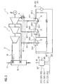
- the power plant 3 comprises a steam generator 10, which is designed for example as a waste heat boiler, which is heated by means of exhaust gas 11 of a gas turbine.
- the power plant 3 comprises a steam turbine 5 which is operated by means of operating steam 40, which is provided by the steam generator 10 as live steam.
- the steam turbine 5 is coupled to generate electrical energy to a generator G, by means of which electrical energy can be fed into a power grid.
- the relaxed steam 50 leaves the steam turbine 5 and is supplied to a condenser 15; the accumulating there condensate is supplied in a manner not shown way a feedwater treatment of the power plant 3.
- a high-pressure evaporator 12 is provided, which is arranged in the steam generator 10 at its hot end.
- heating capacitors 20, 21, 22 are provided for generating district heating, which are each heated with a partial heating steam flow 301, 302, 303.
- the Schudampfteilströme 301,302,303 are removed from a stream of heating steam 30, which in turn is taken from the steam turbine 5, for example, after a medium pressure stage of the steam turbine 5.
- the Schudampfteilstrom 301,302,303 can be taken from the steam turbine 5 also from different Dampfanzapfonne, each with different energy content.
- the heating capacitors 20,21,22 are each flowed through by a aufloomenden medium, which emits thermal energy to heat consumer 201,202,203, for heating purposes, for example.
- the steam provided by the steam generator 10 is thus converted into both electrical and thermal energy (district heating).
- the provision of a required steam power by the steam generator 10 is accomplished by means of a control device of the steam generator 10, which is not shown in the figure; At least one power setpoint must be supplied to the control device, starting from which a corresponding steam generation takes place.
- the power setpoint includes a first set point (not shown in the drawing), which includes an electrical power of the power plant 3, and a second setpoint value 60, which includes a district heat output of the power plant 3.
- the first setpoint results from a power request to the power plant 3, wherein usually an electrical load schedule is predetermined by a control center, for example, for the next 24 hours.
- the second setpoint value 60 relates to the district heat output (reduced electric power) of the power plant 3, which is provided by means of the heating steam 30 or the heating steam partial flows 301, 302, 303 and the heating condensers 20, 21, 22.
- a computing unit 52 is now provided with respect to the second setpoint value 60, by means of which the second setpoint value 60 is calculated on the basis of variables determined in the region of the district heat extraction.
- the arithmetic unit 52 is supplied with at least values for the mass flows 2013,2023,2033 of the medium to be heated in the secondary circuits of the heating capacitors 20,21,22, their flow temperatures 2011,2021,2031 and their return temperatures 2012,2022,2032.
- the mass flows and the aforementioned flow and return temperatures can be detected, for example, by means of sensors and fed to the arithmetic unit 52 as corresponding measured values.
- the determination of the second desired value 60 by the arithmetic unit 52 is advantageously effected by means of the formulas mentioned earlier in the description, according to which the heating steam mass flow of the heating steam 30 is calculated from the mass flows of the medium to be heated and the respective associated flow and return temperatures.
- the other occurring in the formulas sizes of the heating steam enthalpy 305, the condensate enthalpy 505, the specific heat capacity 307 of the medium to be heated and the turbine utilization 507 are preferably not measured, but assumed according to the design of the power plant 3 as a constant sizes, which are already known in particular.
- the value for the specific heat capacity 4 19 kJ kg K amount (when using water as the medium to be heated).
- the turbine efficiency 507 can eg 85% and the condensate enthalpy 2300 kJ kg be.
- the second setpoint value 60 determined by means of the arithmetic unit 52 is added to the first setpoint value (this can also be done, for example, by means of the arithmetic unit 52) and fed to the regulating device of the steam generator 10.
- FIG. 2 shows a preferred embodiment of the invention.
- the steam turbine 5 of the power plant 3 comprises three pressure stages, for example a high-pressure, a medium-pressure and a low-pressure stage.
- Heating steam 30 for heating heating capacitors 20,21,22 is the steam turbine 5 taken at different taps so that Schudampfteilströme 301,302,303 of the heating steam 30 have a mutually different energy level.
- the heating capacitor 20 is heated by means of the Schudampfteilstrom 301, which is compared to the other Schudampfteilströmen 302 and 303 at a lower energy level.
- the heating capacitors 21 u. 22 are connected downstream of the heating capacitor 20 in series, so that a medium to be heated said heating capacitors 20,21 u. 22 flows through successively and can be brought by means of the respective downstream heating capacitor to a higher temperature level.
- a medium to be heated said heating capacitors 20,21 u. 22 flows through successively and can be brought by means of the respective downstream heating capacitor to a higher temperature level.
- To set a particular desired temperature of the medium to be heated in the supply lines between the steam turbine 5 and the heating capacitors 21 u. 22 valves connected, so that the amount of heating steam, which by means of Bankdampfteilstrom 302 u. 303 the respective heating capacitors 21 u. 22 is supplied, is adjustable.
- flow temperatures 2011,2021 u. 2031 and the return temperatures 2012,2022 u. 2032 have in the embodiment of FIG. 2 the meaning of exit or inlet temperatures of the medium to be heated from or into the respective heating capacitors.
- formed heat circuit may be one or more heat consumers 201,202,203 connected.
- the heating steam partial stream 303 is obtained after a heat exchanger surface 42.
- a control flap is provided to tap off a partial flow of the medium to be heated at the outlet of the heating condenser 22 and feed it via a branch line to the inlet of this heating condenser and / or to supply said partial flow to the inlet of the heating condenser 20 via a further control flap.
- the function and mode of operation of the arithmetic unit 52 of the FIG. 2 corresponds to that of FIG. 1 ,
- the present invention can be outlined as follows:
- a power component which accounts for the decoupling of district heating, determined by using a Schudampfmassenstroms, with the aid of a mass flow, a flow and a return temperature of the to be heated medium with respect to the heating capacitor, a heating steam enthalpy and a specific heat capacity of the medium to be heated is calculated, and a condensate enthalpy and a turbine utilization ratio and the heating steam enthalpy.
- the mass flows, as well as the flow and return temperatures can easily in the field of district heating extraction be determined, so that in particular costly measurements in the range of a steam turbine, by means of which the heating capacitors are supplied with heating steam can be avoided.
Abstract
Description
Die Erfindung betrifft ein Verfahren sowie eine Vorrichtung zur Regelung eines kraft-wärme-gekoppelten Kraftwerks.The invention relates to a method and a device for controlling a power-heat coupled power plant.
Bei vielen bekannten Kraftwerken wird eine vorhandene Einrichtung zur Dampferzeugung sowie eine Dampfturbine zusätzlich zur Erzeugung von elektrischer Energie auch zur Erzeugung von sogenannter Fernwärme benutzt, wobei teilentspannter Dampf, welcher noch genügend Energie zur Aufheizung eines aufzuheizenden Mediums besitzt, der Dampfturbine entnommen und einem oder mehreren Heizkondensatoren primärseitig als Heizmedium zugeführt wird. Sekundärseitig werden derartige Heizkondensatoren vom aufzuheizenden Medium, beispielsweise Wasser, durchströmt, welches mittels des Heizmediums aufgeheizt und Wärmeverbrauchern zugeführt wird.In many known power plants, an existing means for generating steam and a steam turbine is used in addition to generating electrical energy for the production of so-called district heating, with partially relaxed steam, which still has enough energy to heat a medium to be heated, the steam turbine removed and one or more heating condensers primary side is supplied as a heating medium. On the secondary side, such heating condensers are flowed through by the medium to be heated, for example water, which is heated by means of the heating medium and supplied to heat consumers.
Auf diese Weise ist es möglich, die Energieerzeugung des Kraftwerks sowohl für die Erzeugung von elektrischer Energie als auch von Fernwärme, beispielsweise zu Heizzwecken, einzusetzen, wobei sich in der Regel ein guter Gesamtwirkungsgrad erzielen lässt.In this way, it is possible to use the energy production of the power plant both for the production of electrical energy and district heating, for example for heating purposes, with a good overall efficiency can be achieved as a rule.
Beachtet werden muss dabei, dass in Folge der Fernwärmeauskopplung ein Teil der Wärmeenergie des Prozessdampfes nicht mehr für die Erzeugung von elektrischer Energie zur Verfügung steht. Wenn nun das Kraftwerk eine angeforderte Menge an elektrischer Leistung zur Verfügung stellen soll, die beispielsweise in Form eines Lastfahrplans von einer übergeordneten Leitzentrale vorgegeben wird, so muss bei der Regelung der Dampferzeugung des Kraftwerks neben der geforderten elektrischen Leistung auch derjenige Leistungsanteil berücksichtigt werden, welcher zur Erzeugung der Fernwärme benötigt wird und welcher, wie bereits erwähnt, nicht zur Erzeugung von elektrischer Energie zur Verfügung steht.It should be noted that as a result of the district heating extraction part of the heat energy of the process steam is no longer available for the generation of electrical energy. Now, if the power plant to provide a requested amount of electrical power available, which is given for example in the form of a load schedule by a parent control center, so must be considered in the regulation of steam generation of the power plant in addition to the required electrical power and that power component, which Generation of district heating is needed and which, as already mentioned, is not available for the generation of electrical energy.
Dies bedeutet, dass beispielsweise eine Regelungseinrichtung eines Dampferzeugers des Kraftwerks mit einem größeren Leistungssollwert beaufschlagt wird, als es allein zur Erzeugung von elektrischer Energie nötig wäre.This means that, for example, a control device of a steam generator of the power plant is subjected to a greater power setpoint than would be necessary solely for the generation of electrical energy.
Derjenige Anteil an Leistung, welcher auf die Fernwärmeauskopplung entfällt, wird als so genannte elektrische Minderleistung bezeichnet, welche zur (geforderten) elektrischen Leistung des Kraftwerks zu addieren und als entsprechender Leistungssollwert einem Leistungsregler des Kraftwerke zuzuführen ist.The proportion of power that is attributable to the district heat extraction is referred to as a so-called electrical shortage, which to add to the (required) electrical power of the power plant and is to be supplied as a corresponding power setpoint a power controller of the power plants.
Bekannte Verfahren und Vorrichtungen zur Bestimmung der oben genannten elektrischen Minderleistung machen meist von empirisch gefundenen Zusammenhängen Gebrauch, wobei z.B. der Druck, mittels welcher die Turbinenschaufeln einer Hochdruckstufe der Dampfturbine beaufschlagt sind, herangezogen wird. Andere Einflüsse, wie beispielsweise eine variierende, insbesondere höhere, Kühlwassertemperatur oder Abschaltungen von Vorwärmern, können dabei oft nicht berücksichtigt werden.Known methods and apparatus for determining the above-mentioned electrical under-performance usually make use of empirically found relationships, e.g. the pressure, by means of which the turbine blades of a high pressure stage of the steam turbine are applied, is used. Other influences, such as a varying, in particular higher, cooling water temperature or shutdowns of preheaters, often can not be taken into account.
Zusammengefasst lässt sich feststellen, dass zur Bestimmung der elektrischen Minderleistung im Stand der Technik in starkem Maß die Dampfturbine betreffende Betriebsparameter herangezogen werden, so dass insbesondere eine für ein bestimmtes Kraftwerk gefundene Ermittlungsmethode der elektrischen Minderleistung nicht ohne Weiteres auf ein anderes Kraftwerk übertragen werden kann, weil die entsprechenden Betriebsparameter der jeweiligen Dampfturbinen sehr stark vom jeweiligen Typ der Dampfturbine abhängen und für eine Dampfturbine empirisch gefundene Zusammenhänge deshalb nicht ohne Weiteres auf eine andere Dampfturbine übertragen werden können.In summary, it can be stated that in order to determine the electrical shortage in the prior art, the operating parameters relating to the steam turbine are used to a great extent, so that in particular a method of determining the electrical shortage found for a specific power plant can not be readily transferred to another power plant because The corresponding operating parameters of the respective steam turbines depend very strongly on the particular type of steam turbine and empirically found relationships for a steam turbine therefore can not be transferred to another steam turbine without further notice.
Der Erfindung liegt daher die Aufgabe zugrunde, ein verbessertes Verfahren sowie eine Vorrichtung zur Leistungs-Regelung.eines kraft-wärme-gekoppelten Kraftwerks anzugeben, mittels welcher in einfacher Weise insbesondere die elektrische Minderleistung bestimmt und berücksichtigt werden kann.The invention is therefore an object of the invention to provide an improved method and a device for power control.eines cogeneration power plant, by means of which in particular the electrical power loss can be determined and taken into account in a simple manner.
Dabei soll das erfindungsgemäße Verfahren sowie die Vorrichtung ohne besondere Schwierigkeiten bei einer Vielzahl an Kraftwerken anwendbar serin.In this case, the inventive method and the device without special difficulties in a variety of power plants applicable serin.
Bezüglich des Verfahrens und der Vorrichtung wird die Aufgabe erfindungsgemäß gelöst durch ein Verfahren und eine Vorrichtung gemäß den Patentansprüchen 1 bzw. 5.With regard to the method and the device, the object is achieved according to the invention by a method and a device according to
Bevorzugte Ausführungsformen sind den davon jeweils abhängigen Unteransprüchen zu entnehmen.Preferred embodiments are to be taken from the respective dependent dependent claims.
Ein wesentlicher Vorteil des erfindungsgemäßen Verfahren sowie der Vorrichtung ist darin zu sehen, dass zur Bestimmung des zweiten Leistungssollwerts (=elektrische Minderleistung) lediglich Messungen im Bereich der Fernwärme nötig sind und keine turbinenspezifischen Einflussparameter und Messgrößen ermittelt und in Betracht gezogen werden müssen.An essential advantage of the method according to the invention and of the device is the fact that for the determination of the second power setpoint (= reduced electrical power) only measurements in the area of district heating are necessary and no turbine-specific influencing parameters and measured variables have to be determined and taken into account.
So müssen zur Bestimmung des zweiten Sollwerts nur der oder die Massenströme des aufzuheizenden Mediums durch den oder die Heizkondensatoren, sowie die Vor- und Rücklauftemperatur des aufzuheizenden Mediums bezüglich jedes Heizkondensators ermittelt werden, beispielsweise durch Messungen. Da die genannten Größen bei vielen kraft-wärme-gekoppelten Kraftwerken sowieso erfasst und in einem vorhandenen Leitsystem verarbeitet werden, ist in sehr vielen Fällen kein zusätzlicher Aufwand für die Ermittlung der besagten Größen notwendig.Thus, only the mass flow or streams of the medium to be heated by the one or more heating capacitors, and the flow and return temperature of the medium to be heated with respect to each heating capacitor must be determined to determine the second setpoint, for example by measurements. Since these variables are detected anyway in many power-heat coupled power plants and processed in an existing control system, in many cases no additional effort for the determination of said sizes is necessary.
Um die Berechnung der elektrischen Minderleistung besonders einfach durchführen zu können, werden bevorzugt die folgenden vereinfachenden Annahmen getroffen:
- Die Auswirkungen der Fernwärmeauskopplung auf Temperaturen und Drücke in der oder den Turbinen können vernachlässigt werden.
- Die Lastabhängigkeit des Enthalpieprofils der Turbine(n) kann vernachlässigt werden.
- Die Auswirkungen auf das Berechnungsergebnis durch anfallende Nebenkondensate können vernachlässigt werden.
- The effects of district heating on temperatures and pressures in the turbine (s) can be neglected.
- The load dependency of the enthalpy profile of the turbine (s) can be neglected.
- The effects on the calculation result by accumulating secondary condensates can be neglected.
Der zweite Sollwert (elektrische Minderleistung) kann dann mittels folgender Formeln bestimmt werden: 
wobei: 
in which:
Mit:
- ṁ Ent :
- Heizdampfmassenstrom
- ṁ Heiz :
- Massenstrom des aufzuheizenden Mediums
- ϑvL :
- Vorlauftemperatur (Austrittstemperatur) des aufzuheizenden Mediums
- ϑRL :
- Rücklauftemperatur (Eintrittstemperatur) des aufzuheizenden Mediums
- hEnt :
- Heizdampf-Enthalpie
- hkond :
- Kondensat-Enthalpie

- Cw :
- spezifische Wärmekapazität des aufzuheizenden Mediums

- εT :
- Turbinen-Ausnutzungsgrad
- ΔPG :
- zweiter Sollwert (elektrische Minderleistung)
- ṁ Ent:
- Heizdampfmassenstrom
- ṁ heating :
- Mass flow of the medium to be heated
- θ vL :
- Flow temperature (outlet temperature) of the medium to be heated
- θ RL :
- Return temperature (inlet temperature) of the medium to be heated
- h ent :
- Heating steam enthalpy
- h cond :
- Condensate enthalpy
- C w :
- specific heat capacity of the heat to be heated medium
- ε T :
- Turbine utilization
- ΔP G :
- second setpoint (electrical power loss)
Eine grundlegende Idee des vorgeschlagenen Verfahrens besteht darin, den Heizdampfmassenstrom zu berechnen unter Zuhilfenahme von Größen im Bereich der Fernwärmeauskopplung, anstatt turbinenseitige Messungen vornehmen zu müssen.A basic idea of the proposed method is to calculate the heating steam mass flow with the aid of variables in the field of district heating decoupling, instead of having to carry out turbine-side measurements.
Gemäß oben stehender Formeln ergibt sich der Heizdampfmassenstrom im Wesentlichen aus den Massenströmen des aufzuheizenden Mediums durch die Heizkondensatoren, sowie den dabei auftretenden Vorlauf- und Rücklauftemperaturen.According to the above formulas, the heating steam mass flow essentially results from the mass flows of the medium to be heated by the heating condensers, as well as the flow and return temperatures occurring in the process.
Die darüber hinaus auftretenden Größen der Heizdampf-Enthalpie, der Kondensat-Enthalpie, der spezifischen Wärmekapazität des aufzuheizenden Mediums sowie des Turbinen-Ausnutzungsgrads werden bevorzugt als konstant angenommen, da deren Werte im Wesentlichen bestimmt sind durch die Auslegung der Anlage und weniger von aktuellen Betriebsbedingungen.The additionally occurring quantities of the heating-steam enthalpy, the condensate enthalpy, the specific heat capacity of the medium to be heated and the turbine utilization ratio are preferably assumed to be constant, since their values are essentially determined by the design of the system and less by current operating conditions.
Sind in einer Anlage mehrere Heizkondensatoren vorhanden, so sind obige Formeln für jeden Heizkondensator auszuwerten und die entsprechenden Ergebnisse für den zweiten Sollwert zu addieren.If several heating capacitors are present in a system, the above formulas for each heating capacitor must be evaluated and the corresponding results for the second setpoint added.
Bei der Heizdampf-Enthalpie handelt es sich um den Energieinhalt pro kg an Heizdampf, welcher in einen Heizkondensator primärseitig eingespeist wird.The heating steam enthalpy is the energy content per kg of heating steam, which is fed into the primary side of a heating condenser.
Die Kondensat-Enthalpie beschreibt den Energieinhalt pro kg an entspanntem Dampf, welcher eine Dampf-Turbine verlässt und in einen Kondensator eingespeist wird.The condensate enthalpy describes the energy content per kg of relaxed steam, which leaves a steam turbine and is fed into a condenser.
Die spezifische Wärmekapazität des aufzuheizenden Mediums ist eine Stoffeigenschaft dieses Mediums und kann für das jeweils verwendete aufzuheizende Medium (beispielsweise Wasser) einschlägigen Nachschlagewerken entnommen werden.The specific heat capacity of the medium to be heated is a substance property of this medium and can be taken from the relevant reference books used for the respective medium to be heated (for example water).
Der Turbinen-Ausnutzungsgrad ist im Wesentlichen bestimmt durch die Auslegung der Turbine für einen Nennbetrieb.The turbine utilization rate is essentially determined by the design of the turbine for nominal operation.
Im Folgenden werden zwei Ausführungsbeispiele der Erfindung näher dargestellt. Es zeigt:
-
FIG 1 eine erfindungsgemäße Vorrichtung zur Regelung der Leistung eines kraft-wärme-gekoppelten Kraftwerks und -
FIG 2 eine bevorzugte Ausführungsform der Erfindung.
-
FIG. 1 a device according to the invention for controlling the power of a cogeneration power plant and -
FIG. 2 a preferred embodiment of the invention.
In der Figur ist eine Vorrichtung 1 zur Regelung der Leistung eines kraft-wärme-gekoppelten Kraftwerks 3 dargestellt. Das Kraftwerk 3 umfasst dabei einen Dampferzeuger 10, welcher beispielsweise als ein Abhitzekessel ausgebildet ist, welcher mittels Abgas 11 einer Gasturbine beheizt ist.In the figure, a device 1 for controlling the power of a combined heat and
Weiterhin umfasst das Kraftwerk 3 eine Dampfturbine 5, welche mittels Betriebsdampf 40, welcher vom Dampferzeuger 10 als Frischdampf bereitgestellt ist, betrieben wird.Furthermore, the
Die Dampfturbine 5 ist zur Erzeugung von elektrischer Energie an einen Generator G gekoppelt, mittels welchem elektrische Energie in ein Energieversorgungsnetz einspeisbar ist.The
Nach Verrichtung von Arbeit in der Dampfturbine 5 verlässt entspannter Dampf 50 die Dampfturbine 5 und wird einem Kondensator 15 zugeführt; das sich dort ansammelnde Kondensat wird in nicht näher dargestellter Art und Weise einer Speisewasseraufbereitung des Kraftwerks 3 zugeführt.After performing work in the
Zur Erzeugung des Betriebsdampfs 40 für die Dampfturbine 5 ist im vorliegenden Ausführungsbeispiel ein Hochdruckverdampfer 12 vorgesehen, welcher im Dampferzeuger 10 an dessen heißen Ende angeordnet ist.For generating the operating
Da es sich bei dem Kraftwerk 3 um ein kraft-wärme-gekoppeltes Kraftwerk handelt, sind zur Erzeugung von Fernwärme Heizkondensatoren 20,21,22 vorgesehen, welche jeweils mit einem Heizdampfteilstrom 301,302,303 beheizt sind. Die Heizdampfteilströme 301,302,303 sind einem Strom an Heizdampf 30 entnommen, welcher wiederum der Dampfturbine 5 entnommen ist, beispielsweise nach einer Mitteldruckstufe der Dampfturbine 5. Die Heizdampfteilströme 301,302,303 können dabei der Dampfturbine 5 auch aus unterschiedlichen Dampfanzapfungen mit jeweils unterschiedlichem Energieinhalt entnommen sein.Since the
Die Heizkondensatoren 20,21,22 sind jeweils von einem aufzuheizenden Medium durchströmt, welches an Wärmeverbraucher 201,202,203 Wärmeenergie abgibt, beispielsweise zu Heizzwecken.The
Die durch den Dampferzeuger 10 bereit gestellte Dampfleistung wird also sowohl in elektrische, als auch in Wärmeenergie (Fernwärme) umgewandelt.The steam provided by the
Die Bereitstellung einer benötigten Dampfleistung durch den Dampferzeuger 10 wird mittels einer Regelungseinrichtung des Dampferzeugers 10 bewerkstelligt, welche in der Figur nicht dargestellt ist; der Regelungseinrichtung muss zumindest ein Leistungssollwert zugeführt werden, ausgehend von welchem eine entsprechende Dampferzeugung stattfindet.The provision of a required steam power by the
Im Falle des vorliegenden kraft-wärme-gekoppelten Kraftwerks 3 umfasst der Leistungssollwert einen ersten Sollwert (in der Zeichnung nicht dargestellt), welcher eine elektrische Leistung des Kraftwerks 3 umfasst, und einen zweiten Sollwert 60, welcher eine Fernwärmeleistung des Kraftwerks 3 umfasst.In the case of the present combined heat and
Der erste Sollwert ergibt sich aus einer Leistungsanforderung an das Kraftwerk 3, wobei üblicherweise ein elektrischer Lastfahrplan durch eine Leitzentrale vorgegeben ist, beispielsweise für die nächsten 24 Stunden.The first setpoint results from a power request to the
Der zweite Sollwert 60 bezieht sich auf die Fernwärmeleistung (elektrische Minderleistung) des Kraftwerks 3, welche mittels des Heizdampfs 30 bzw. der Heizdampfteilströme 301,302,303 und der Heizkondensatoren 20,21,22 bereitgestellt wird.The
Bei der Vorgabe des Leistungssollwerts für die Regelungseinrichtung des Dampferzeugers 10 ist nun bezüglich des zweiten Sollwerts 60 eine Recheneinheit 52 vorgesehen, mittels welcher anhand von im Bereich der Fernwärmeauskopplung ermittelten Größen der zweite Sollwert 60 berechnet wird.When presetting the power setpoint for the control device of the
Dazu sind der Recheneinheit 52 mindestens Werte für die Massenströme 2013,2023,2033 des in den Sekundärkreisläufen der Heizkondensatoren 20,21,22 jeweils geführten aufzuheizenden Mediums, deren Vorlauftemperaturen 2011,2021,2031 sowie deren Rücklauftemperaturen 2012,2022,2032 zugeführt.For this purpose, the
Die Massenströme und die genannten Vorlauf- und Rücklauftemperaturen können beispielsweise mittels Sensoren erfasst und als entsprechende Messwerte der Recheneinheit 52 zugeführt sein.The mass flows and the aforementioned flow and return temperatures can be detected, for example, by means of sensors and fed to the
Die Bestimmung des zweiten Sollwerts 60 durch die Recheneinheit 52 geschieht vorteilhaft mittels der an früherer Stelle der Beschreibung genannten Formeln, wonach der Heizdampfmassenstrom des Heizdampfs 30 berechnet wird aus den Massenströmen des aufzuheizenden Mediums sowie den jeweils zugehörigen Vorlauf- und Rücklauftemperaturen.The determination of the second desired
Die weiteren in den Formeln auftretenden Größen der Heizdampf-Enthalpie 305, der Kondensat-Enthalpie 505, der spezifischen Wärmekapazität 307 des aufzuheizenden Mediums sowie des Turbinen-Ausnutzungsgrads 507 werden bevorzugt nicht gemessen, sondern entsprechend der Auslegung des Kraftwerks 3 als konstante Größen angenommen, welche insbesondere schon bekannt sind.The other occurring in the formulas sizes of the
Beispielsweise kann der Wert für die spezifische Wärmekapazität ![]()
![]()
Der Turbinen-Ausnutzungsgrad 507 kann z.B. 85 % und die Kondensat-Enthalpie 
Die Werte für die Heizdampf-Enthalpie 305 der Heizkondensatoren 20,21,22 können beispielsweise wie folgt gegeben sein
- Heizdampf-
Enthalpie 305 des Heizkondensators 20:
- Heizdampf-
Enthalpie 305 des Heizkondensators 21:
- Heizdampf-
Enthalpie 305 des Heizkondensators 22:
-
Heating steam enthalpy 305 of the heating capacitor 20: -
Heating steam enthalpy 305 of the heating capacitor 21: -
Heating steam enthalpy 305 of the heating capacitor 22:
Der mittels der Recheneinheit 52 ermittelte zweite Sollwert 60 wird zum ersten Sollwert addiert (dies kann beispielsweise ebenfalls mittels der Recheneinheit 52 geschehen) und der Regelungseinrichtung des Dampferzeugers 10 zugeführt.The
Die Dampfturbine 5 des Kraftwerks 3 umfasst dabei drei Druckstufen, beispielsweise eine Hochdruck-, eine Mitteldruck- und eine Niederdruckstufe.The
Heizdampf 30 zur Beheizung von Heizkondensatoren 20,21,22 ist dabei der Dampfturbine 5 an verschiedenen Anzapfungen entnommen, so dass Heizdampfteilströme 301,302,303 des Heizdampfs 30 ein zueinander unterschiedliches Energieniveau aufweisen.
Im Ausführungsbeispiel der
Die Heizkondensatoren 21 u. 22 sind dem Heizkondensator 20 in Reihe nachgeschaltet, so dass ein aufzuheizendes Medium die genannten Heizkondensatoren 20,21 u. 22 nacheinander durchströmt und mittels des jeweils nachgeordneten Heizkondensators auf ein höheres Temperaturniveau gebracht werden kann. Zur Einstellung einer jeweils gewünschten Temperatur des aufzuheizenden Mediums sind in die Versorgungsleitungen zwischen der Dampfturbine 5 und den Heizkondensatoren 21 u. 22 Ventile geschaltet, so dass die Heizdampfmenge, welche mittels der Heizdampfteilströme 302 u. 303 den jeweiligen Heizkondensatoren 21 u. 22 zugeführt wird, einstellbar ist.The heating capacitors 21 u. 22 are connected downstream of the
Die in
Die im Zusammenhang mit
In den mittels der Heizkondensatoren 20,21 u. 22 gebildeten Wärmekreislauf können ein oder mehrere Wärmeverbraucher 201,202,203 geschaltet sein.In the means of the
Im Ausführungsbeispiel der
Bei der Kaskadenschaltung der Heizkondensatoren 20,21 u. 22 können weitere Steuerungselemente zur Einstellung gewünschter Teilströme des aufzuheizenden Mediums vorgesehen sein, beispielsweise Steuerungsklappen oder Ventile, oder auch Abzweigleitungen. Im Beispiel der
Neben der gezeigten Ausführung der Kaskadenschaltung bezüglich der Heizkondensatoren 20,21 u. 22 sind eine Reihe weiterer Variationen denkbar.In addition to the illustrated embodiment of the cascade circuit with respect to the
Die Funktion und Wirkungsweise der Recheneinheit 52 der
Zusammengefasst lässt sich die vorliegende Erfindung wie folgt umreißen:In summary, the present invention can be outlined as follows:
Bei einem erfindungsgemäßen Verfahren sowie einer erfindungsgemäßen Vorrichtung zur Regelung der Leistung eines kraft-wärme-gekoppelten Kraftwerks wird derjenige Leistungsanteil, welcher auf die Auskopplung der Fernwärme entfällt, bestimmt unter Heranziehung eines Heizdampfmassenstroms, der unter Zuhilfenahme eines Massenstroms, einer Vorlauf- sowie einer Rücklauftemperatur des aufzuheizenden Mediums bezüglich des Heizkondensators, einer Heizdampf-Enthalpie und einer spezifischen Wärmekapazität des aufzuheizenden Mediums berechnet wird, sowie einer Kondensat-Enthalpie und eines Turbinen-Ausnutzungsgrads und der Heizdampf-Enthalpie.In a method according to the invention and a device according to the invention for controlling the power of a cogeneration power plant is that power component, which accounts for the decoupling of district heating, determined by using a Heizdampfmassenstroms, with the aid of a mass flow, a flow and a return temperature of the to be heated medium with respect to the heating capacitor, a heating steam enthalpy and a specific heat capacity of the medium to be heated is calculated, and a condensate enthalpy and a turbine utilization ratio and the heating steam enthalpy.
Die Massenströme, sowie die Vorlauf- und Rücklauftemperaturen können auf einfache Weise im Bereich der Fernwärmeauskopplung bestimmt werden, so dass insbesondere aufwendige Messungen im Bereich einer Dampfturbine, mittels welcher die Heizkondensatoren mit Heizdampf versorgt sind, vermieden werden.The mass flows, as well as the flow and return temperatures can easily in the field of district heating extraction be determined, so that in particular costly measurements in the range of a steam turbine, by means of which the heating capacitors are supplied with heating steam can be avoided.
Claims (6)
- Method for regulating the power output of a combined-cycle power station (3), at least one desired power output value, by means of which at least one regulating device of an energy generator, in particular of a steam generator (10), of the combined-cycle power station (3) is acted upon, being determined from at least one first desired value, which comprises an electrical power output of the power station (1), and from a second desired value (60), which comprises a distance heat power output of the power station (3), and the power station (3) comprising at least one heating condenser (20, 21, 22) for the generation of distance heat, through which a medium to be heated flows from the secondary side, characterized in that, to determine the second desired value (60), a heating-steam mass flow, which is calculated with the aid of a mass flow (2013, 2023, 2033), of a forward-flow temperature (2011, 2021), 2031) and return-flow temperature (2012, 2022, 2032) of the medium to be heated with respect to the heating condenser (20, 21, 22), of a heating-steam enthalpy (305) and of a specific heat capacity (307) of the medium to be heated, and also a condensate enthalpy (505) and a turbine degree of utilization (507) and the heating-steam enthalpy (305) are employed.
- Method according to Claim 1, characterized in that the heating condenser (20, 21, 22) is heated on the primary side by heating steam (30) which is extracted from a steam turbine (5) of the power station (3), and in that the power station (3) comprises at least one condenser (15), into which expanded steam (50), which leaves the steam turbine (5), is fed.
- Method according to Claim 1 or 2, characterized in that, to determine the second desired value (60) the following formula is employed:

in which
- Method according to one of Claims 1 to 3, characterized in that the heating-steam enthalpy, the condensate enthalpy, the specific heat capacity of the medium to be heated and the turbine degree of utilization are assumed to be constant.
- Device (1) for regulating the power output of a combined-cycle power station (3), at least one desired power output value, by means of which at least one regulating device of an energy generator, in particular of a steam generator (10) of the combined-cycle power station (3) is acted upon, being determinable from at least one first desired value, which comprises an electrical power output of the power station (3), and from a second desired value (60), which comprises a distance heat power output of the power station (3), and the power station (3) comprising at least one heating condenser (20, 21, 22) for the generation of distance heat, through which a medium to be heated is capable of flowing on the secondary side, characterized by a computing unit (52) for calculating a heating-steam mass flow from the following variables: mass flow (2013, 2023, 2033), forward-flow temperature (2011, 2021, 2031), return-flow temperature (2012, 2022, 2032), heating-steam enthalpy (305) and specific heat capacity (301) of the medium to be heated, which relate to the medium to be heated which is routed through the heating condenser (20, 21, 22), and for determining the second desired value (60) at least from the following variables: heating-steam mass flow, condensate enthalpy (505), turbine degree of utilization (507) and heating-steam enthalpy (305).
- Device (1) according to Claim 5, characterized in that the power station (3) comprises at least one steam turbine (5) and one condenser (15) connected to the steam turbine (5), and in that the heating condenser (20, 21, 22) is capable of being steam-heated and is connected to the steam turbine (5) on the primary side.
Priority Applications (5)
| Application Number | Priority Date | Filing Date | Title |
|---|---|---|---|
| DE50214137T DE50214137D1 (en) | 2002-11-21 | 2002-11-21 | Method and device for regulating the power of a combined heat and power plant |
| EP02026036A EP1426564B1 (en) | 2002-11-21 | 2002-11-21 | Method and device for controlling the output of a combined heat and power plant |
| ES02026036T ES2337340T3 (en) | 2002-11-21 | 2002-11-21 | PROCEDURE AND DEVICE FOR THE REGULATION OF THE POWER OF AN ENGINEER AND HEAT COMBINED PRODUCTION POWER PLANT. |
| AT02026036T ATE453781T1 (en) | 2002-11-21 | 2002-11-21 | METHOD AND DEVICE FOR CONTROLLING THE PERFORMANCE OF A CHP COMBINED POWER PLANT |
| US10/717,537 US7055328B2 (en) | 2002-11-21 | 2003-11-21 | Method and device for regulating the power output of a combined-cycle power station |
Applications Claiming Priority (1)
| Application Number | Priority Date | Filing Date | Title |
|---|---|---|---|
| EP02026036A EP1426564B1 (en) | 2002-11-21 | 2002-11-21 | Method and device for controlling the output of a combined heat and power plant |
Publications (2)
| Publication Number | Publication Date |
|---|---|
| EP1426564A1 EP1426564A1 (en) | 2004-06-09 |
| EP1426564B1 true EP1426564B1 (en) | 2009-12-30 |
Family
ID=32309339
Family Applications (1)
| Application Number | Title | Priority Date | Filing Date |
|---|---|---|---|
| EP02026036A Expired - Lifetime EP1426564B1 (en) | 2002-11-21 | 2002-11-21 | Method and device for controlling the output of a combined heat and power plant |
Country Status (5)
| Country | Link |
|---|---|
| US (1) | US7055328B2 (en) |
| EP (1) | EP1426564B1 (en) |
| AT (1) | ATE453781T1 (en) |
| DE (1) | DE50214137D1 (en) |
| ES (1) | ES2337340T3 (en) |
Families Citing this family (12)
| Publication number | Priority date | Publication date | Assignee | Title |
|---|---|---|---|---|
| DE10317183B4 (en) * | 2003-04-15 | 2007-04-05 | SWE Strom und Fernwärme GmbH | Temporary increase by electric energy generated by CHP |
| DE102004008588B3 (en) * | 2004-02-19 | 2005-10-20 | Enginion Ag | Steam regulating system for a heating system in a building comprises a burner for producing heat, a heat transfer unit for transferring heat to a working medium, an expansion machine, a pump, a condenser and a heat regulating unit |
| CN101769552B (en) * | 2008-12-29 | 2012-08-08 | 河北盛华化工有限公司 | Low-vacuum-operating circulating water heating system of steam turbine in thermal power plant |
| EP2244011A1 (en) * | 2009-03-24 | 2010-10-27 | Siemens AG | Method and device for regulating the temperature of steam for a steam power plant |
| US9046006B2 (en) * | 2010-06-21 | 2015-06-02 | Paccar Inc | Dual cycle rankine waste heat recovery cycle |
| JP2013545916A (en) * | 2010-10-19 | 2013-12-26 | アルストム テクノロジー リミテッド | Method for operating a combined cycle power plant for cogeneration and a combined cycle power plant for implementing the method |
| EP2589760B1 (en) * | 2011-11-03 | 2020-07-29 | General Electric Technology GmbH | Steam power plant with high-temperature heat reservoir |
| EP2764298B1 (en) * | 2012-01-23 | 2018-02-28 | Siemens Aktiengesellschaft | Cogeneration plant and operation method therefor |
| CN103884037A (en) * | 2014-03-11 | 2014-06-25 | 济钢集团有限公司 | Circulating water heat exchange system of heating network |
| DE102014004287A1 (en) * | 2014-03-26 | 2015-10-01 | Vattenfall Europe Powerconsult Gmbh | Method for power regulation of gas and steam cogeneration plants with counter-pressure steam turbine (s) for full participation in the primary and secondary control while controlling the heat load |
| CN105257352A (en) * | 2015-09-25 | 2016-01-20 | 东方电气集团东方汽轮机有限公司 | Industrial heat supply steam extraction method |
| GB2544063B (en) * | 2015-11-03 | 2018-04-11 | Basic Holdings | Distributed heat pump network |
Family Cites Families (13)
| Publication number | Priority date | Publication date | Assignee | Title |
|---|---|---|---|---|
| US4005581A (en) * | 1975-01-24 | 1977-02-01 | Westinghouse Electric Corporation | Method and apparatus for controlling a steam turbine |
| US4571151A (en) * | 1983-08-26 | 1986-02-18 | General Electric Company | Liquid injection control in multi-stage compressor |
| DE3336596A1 (en) | 1983-10-07 | 1985-04-25 | Siemens AG, 1000 Berlin und 8000 München | Method for controlling a power unit operated in cogeneration of power and heat |
| US4752697A (en) * | 1987-04-10 | 1988-06-21 | International Cogeneration Corporation | Cogeneration system and method |
| GB8715131D0 (en) * | 1987-06-27 | 1987-08-05 | Combined Power Systems Ltd | Building heat & power system |
| DE3841224A1 (en) * | 1988-12-07 | 1990-06-13 | Siemens Ag | Combined gas turbine/steam turbine power station |
| EP0663575B1 (en) * | 1994-01-13 | 2000-04-12 | N.V. Kema | Control for operating boilers and devices for generating heat and power |
| DE19517053A1 (en) * | 1995-05-10 | 1996-11-14 | Ingenieurgesellschaft Fuer En | Operation of thermal network for centrally heated buildings |
| DE19602330C1 (en) * | 1996-01-24 | 1997-06-26 | Meyer Fa Rud Otto | Block-heating power station to generate electricity and supply heat to one or more heat-consumer units |
| DE19621247A1 (en) | 1996-05-25 | 1997-11-27 | Wilo Gmbh | Method and circuit arrangement for remote domestic heat output station |
| DE19859364C2 (en) * | 1998-12-22 | 2001-09-13 | Baelz Gmbh Helmut | Heat supply system with peak load limitation |
| DE10003914A1 (en) * | 1999-02-23 | 2000-10-12 | Friedrich Bude | Generating and distributing electrical and thermal energy from force-heat coupling, especially unit-type thermal power station, involves generating, transporting electrical energy as thermal current |
| US20030213246A1 (en) * | 2002-05-15 | 2003-11-20 | Coll John Gordon | Process and device for controlling the thermal and electrical output of integrated micro combined heat and power generation systems |
-
2002
- 2002-11-21 DE DE50214137T patent/DE50214137D1/en not_active Expired - Lifetime
- 2002-11-21 AT AT02026036T patent/ATE453781T1/en active
- 2002-11-21 EP EP02026036A patent/EP1426564B1/en not_active Expired - Lifetime
- 2002-11-21 ES ES02026036T patent/ES2337340T3/en not_active Expired - Lifetime
-
2003
- 2003-11-21 US US10/717,537 patent/US7055328B2/en not_active Expired - Lifetime
Also Published As
| Publication number | Publication date |
|---|---|
| EP1426564A1 (en) | 2004-06-09 |
| ATE453781T1 (en) | 2010-01-15 |
| US7055328B2 (en) | 2006-06-06 |
| ES2337340T3 (en) | 2010-04-23 |
| DE50214137D1 (en) | 2010-02-11 |
| US20040129002A1 (en) | 2004-07-08 |
Similar Documents
| Publication | Publication Date | Title |
|---|---|---|
| EP0436536B1 (en) | Process and plant for generating steam using waste heat | |
| EP2255076B1 (en) | Method for regulating a boiler and control circuit for a boiler | |
| DE60126721T2 (en) | Combined circulation system with gas turbine | |
| EP1426564B1 (en) | Method and device for controlling the output of a combined heat and power plant | |
| EP2212618B1 (en) | Method for operating a continuous flow steam generator and once-through steam generator | |
| EP2359058A2 (en) | Method for operating a waste heat steam generator | |
| EP0778397A2 (en) | Method of operating a combined power plant with a waste heat boiler and a steam user | |
| DE102010060064A1 (en) | Method for increasing the power output of a gas and steam combined cycle power plant during selected operating periods | |
| DE102011076968A1 (en) | Method for operating a circulation heat recovery steam generator | |
| EP0885348B1 (en) | Process and device for rapid power control of a power station | |
| WO2011020776A2 (en) | Solar thermal power plant having a heat exchanger in the feedwater preheating section and method for operating the power plant | |
| EP1368555B1 (en) | Method for operating a steam power installation and corresponding steam power installation | |
| EP1390606B1 (en) | Device for cooling coolant in a gas turbine and gas and steam turbine with said device | |
| DE19720881A1 (en) | Combined heat and power station with conversion turbines | |
| DE4447044C1 (en) | Method reducing start=up losses in a power plant | |
| DE10155508C5 (en) | Method and device for generating electrical energy | |
| DE102005034847B4 (en) | Steam power plant | |
| EP1614962A1 (en) | Method for operating of an once-through steam generator | |
| DE3137379C2 (en) | Process for supplying district heating networks with heat and a thermal power plant | |
| DE3808006C2 (en) | ||
| EP3728800B1 (en) | Power plant | |
| EP2426337A1 (en) | Device for fuel preheating and method for fuel preheating | |
| DE102010010614B4 (en) | Method and device for generating energy in an ORC system | |
| DE4129115A1 (en) | Steam-generation method using waste heat - involves superheating saturated stream generated in both heating stages | |
| EP3280884B1 (en) | Method for cooling a steam turbine |
Legal Events
| Date | Code | Title | Description |
|---|---|---|---|
| PUAI | Public reference made under article 153(3) epc to a published international application that has entered the european phase |
Free format text: ORIGINAL CODE: 0009012 |
|
| AK | Designated contracting states |
Kind code of ref document: A1 Designated state(s): AT BE BG CH CY CZ DE DK EE ES FI FR GB GR IE IT LI LU MC NL PT SE SK TR |
|
| AX | Request for extension of the european patent |
Extension state: AL LT LV MK RO SI |
|
| 17P | Request for examination filed |
Effective date: 20040706 |
|
| AKX | Designation fees paid |
Designated state(s): AT BE BG CH CY CZ DE DK EE ES FI FR GB GR IE IT LI LU MC NL PT SE SK TR |
|
| 17Q | First examination report despatched |
Effective date: 20050513 |
|
| GRAP | Despatch of communication of intention to grant a patent |
Free format text: ORIGINAL CODE: EPIDOSNIGR1 |
|
| GRAS | Grant fee paid |
Free format text: ORIGINAL CODE: EPIDOSNIGR3 |
|
| GRAA | (expected) grant |
Free format text: ORIGINAL CODE: 0009210 |
|
| AK | Designated contracting states |
Kind code of ref document: B1 Designated state(s): AT BE BG CH CY CZ DE DK EE ES FI FR GB GR IE IT LI LU MC NL PT SE SK TR |
|
| REG | Reference to a national code |
Ref country code: GB Ref legal event code: FG4D Free format text: NOT ENGLISH |
|
| REG | Reference to a national code |
Ref country code: CH Ref legal event code: EP |
|
| REG | Reference to a national code |
Ref country code: IE Ref legal event code: FG4D |
|
| REG | Reference to a national code |
Ref country code: CH Ref legal event code: NV Representative=s name: SIEMENS SCHWEIZ AG |
|
| REF | Corresponds to: |
Ref document number: 50214137 Country of ref document: DE Date of ref document: 20100211 Kind code of ref document: P |
|
| REG | Reference to a national code |
Ref country code: NL Ref legal event code: T3 |
|
| REG | Reference to a national code |
Ref country code: SE Ref legal event code: TRGR |
|
| REG | Reference to a national code |
Ref country code: ES Ref legal event code: FG2A Ref document number: 2337340 Country of ref document: ES Kind code of ref document: T3 |
|
| PG25 | Lapsed in a contracting state [announced via postgrant information from national office to epo] |
Ref country code: FI Free format text: LAPSE BECAUSE OF FAILURE TO SUBMIT A TRANSLATION OF THE DESCRIPTION OR TO PAY THE FEE WITHIN THE PRESCRIBED TIME-LIMIT Effective date: 20091230 |
|
| REG | Reference to a national code |
Ref country code: IE Ref legal event code: FD4D |
|
| PG25 | Lapsed in a contracting state [announced via postgrant information from national office to epo] |
Ref country code: BG Free format text: LAPSE BECAUSE OF FAILURE TO SUBMIT A TRANSLATION OF THE DESCRIPTION OR TO PAY THE FEE WITHIN THE PRESCRIBED TIME-LIMIT Effective date: 20100330 Ref country code: EE Free format text: LAPSE BECAUSE OF FAILURE TO SUBMIT A TRANSLATION OF THE DESCRIPTION OR TO PAY THE FEE WITHIN THE PRESCRIBED TIME-LIMIT Effective date: 20091230 Ref country code: PT Free format text: LAPSE BECAUSE OF FAILURE TO SUBMIT A TRANSLATION OF THE DESCRIPTION OR TO PAY THE FEE WITHIN THE PRESCRIBED TIME-LIMIT Effective date: 20100430 |
|
| PG25 | Lapsed in a contracting state [announced via postgrant information from national office to epo] |
Ref country code: CZ Free format text: LAPSE BECAUSE OF FAILURE TO SUBMIT A TRANSLATION OF THE DESCRIPTION OR TO PAY THE FEE WITHIN THE PRESCRIBED TIME-LIMIT Effective date: 20091230 Ref country code: SK Free format text: LAPSE BECAUSE OF FAILURE TO SUBMIT A TRANSLATION OF THE DESCRIPTION OR TO PAY THE FEE WITHIN THE PRESCRIBED TIME-LIMIT Effective date: 20091230 |
|
| PG25 | Lapsed in a contracting state [announced via postgrant information from national office to epo] |
Ref country code: CY Free format text: LAPSE BECAUSE OF FAILURE TO SUBMIT A TRANSLATION OF THE DESCRIPTION OR TO PAY THE FEE WITHIN THE PRESCRIBED TIME-LIMIT Effective date: 20091230 Ref country code: IE Free format text: LAPSE BECAUSE OF FAILURE TO SUBMIT A TRANSLATION OF THE DESCRIPTION OR TO PAY THE FEE WITHIN THE PRESCRIBED TIME-LIMIT Effective date: 20091230 Ref country code: GR Free format text: LAPSE BECAUSE OF FAILURE TO SUBMIT A TRANSLATION OF THE DESCRIPTION OR TO PAY THE FEE WITHIN THE PRESCRIBED TIME-LIMIT Effective date: 20100331 |
|
| PLBE | No opposition filed within time limit |
Free format text: ORIGINAL CODE: 0009261 |
|
| STAA | Information on the status of an ep patent application or granted ep patent |
Free format text: STATUS: NO OPPOSITION FILED WITHIN TIME LIMIT |
|
| 26N | No opposition filed |
Effective date: 20101001 |
|
| PG25 | Lapsed in a contracting state [announced via postgrant information from national office to epo] |
Ref country code: DK Free format text: LAPSE BECAUSE OF FAILURE TO SUBMIT A TRANSLATION OF THE DESCRIPTION OR TO PAY THE FEE WITHIN THE PRESCRIBED TIME-LIMIT Effective date: 20091230 |
|
| BERE | Be: lapsed |
Owner name: SIEMENS A.G. Effective date: 20101130 |
|
| PG25 | Lapsed in a contracting state [announced via postgrant information from national office to epo] |
Ref country code: MC Free format text: LAPSE BECAUSE OF NON-PAYMENT OF DUE FEES Effective date: 20101130 |
|
| PG25 | Lapsed in a contracting state [announced via postgrant information from national office to epo] |
Ref country code: BE Free format text: LAPSE BECAUSE OF NON-PAYMENT OF DUE FEES Effective date: 20101130 |
|
| PG25 | Lapsed in a contracting state [announced via postgrant information from national office to epo] |
Ref country code: LU Free format text: LAPSE BECAUSE OF NON-PAYMENT OF DUE FEES Effective date: 20101121 |
|
| PGFP | Annual fee paid to national office [announced via postgrant information from national office to epo] |
Ref country code: SE Payment date: 20121113 Year of fee payment: 11 Ref country code: TR Payment date: 20121031 Year of fee payment: 11 Ref country code: ES Payment date: 20121207 Year of fee payment: 11 Ref country code: IT Payment date: 20121129 Year of fee payment: 11 |
|
| PGFP | Annual fee paid to national office [announced via postgrant information from national office to epo] |
Ref country code: FR Payment date: 20121214 Year of fee payment: 11 Ref country code: AT Payment date: 20121010 Year of fee payment: 11 Ref country code: NL Payment date: 20121105 Year of fee payment: 11 |
|
| PGFP | Annual fee paid to national office [announced via postgrant information from national office to epo] |
Ref country code: CH Payment date: 20130211 Year of fee payment: 11 |
|
| REG | Reference to a national code |
Ref country code: NL Ref legal event code: V1 Effective date: 20140601 |
|
| REG | Reference to a national code |
Ref country code: CH Ref legal event code: PL |
|
| REG | Reference to a national code |
Ref country code: SE Ref legal event code: EUG |
|
| REG | Reference to a national code |
Ref country code: AT Ref legal event code: MM01 Ref document number: 453781 Country of ref document: AT Kind code of ref document: T Effective date: 20131121 |
|
| PG25 | Lapsed in a contracting state [announced via postgrant information from national office to epo] |
Ref country code: CH Free format text: LAPSE BECAUSE OF NON-PAYMENT OF DUE FEES Effective date: 20131130 Ref country code: LI Free format text: LAPSE BECAUSE OF NON-PAYMENT OF DUE FEES Effective date: 20131130 |
|
| REG | Reference to a national code |
Ref country code: FR Ref legal event code: ST Effective date: 20140731 |
|
| PG25 | Lapsed in a contracting state [announced via postgrant information from national office to epo] |
Ref country code: NL Free format text: LAPSE BECAUSE OF NON-PAYMENT OF DUE FEES Effective date: 20140601 Ref country code: SE Free format text: LAPSE BECAUSE OF NON-PAYMENT OF DUE FEES Effective date: 20131122 Ref country code: IT Free format text: LAPSE BECAUSE OF NON-PAYMENT OF DUE FEES Effective date: 20131121 Ref country code: AT Free format text: LAPSE BECAUSE OF NON-PAYMENT OF DUE FEES Effective date: 20131121 |
|
| PG25 | Lapsed in a contracting state [announced via postgrant information from national office to epo] |
Ref country code: FR Free format text: LAPSE BECAUSE OF NON-PAYMENT OF DUE FEES Effective date: 20131202 |
|
| REG | Reference to a national code |
Ref country code: ES Ref legal event code: FD2A Effective date: 20150710 |
|
| PG25 | Lapsed in a contracting state [announced via postgrant information from national office to epo] |
Ref country code: ES Free format text: LAPSE BECAUSE OF NON-PAYMENT OF DUE FEES Effective date: 20131122 |
|
| PG25 | Lapsed in a contracting state [announced via postgrant information from national office to epo] |
Ref country code: TR Free format text: LAPSE BECAUSE OF NON-PAYMENT OF DUE FEES Effective date: 20131121 |
|
| REG | Reference to a national code |
Ref country code: DE Ref legal event code: R081 Ref document number: 50214137 Country of ref document: DE Owner name: SIEMENS GAS AND POWER GMBH & CO. KG, DE Free format text: FORMER OWNER: SIEMENS AKTIENGESELLSCHAFT, 80333 MUENCHEN, DE Ref country code: DE Ref legal event code: R081 Ref document number: 50214137 Country of ref document: DE Owner name: SIEMENS ENERGY GLOBAL GMBH & CO. KG, DE Free format text: FORMER OWNER: SIEMENS AKTIENGESELLSCHAFT, 80333 MUENCHEN, DE |
|
| REG | Reference to a national code |
Ref country code: GB Ref legal event code: 732E Free format text: REGISTERED BETWEEN 20201001 AND 20201007 |
|
| REG | Reference to a national code |
Ref country code: DE Ref legal event code: R081 Ref document number: 50214137 Country of ref document: DE Owner name: SIEMENS ENERGY GLOBAL GMBH & CO. KG, DE Free format text: FORMER OWNER: SIEMENS GAS AND POWER GMBH & CO. KG, 80333 MUENCHEN, DE |
|
| PGFP | Annual fee paid to national office [announced via postgrant information from national office to epo] |
Ref country code: GB Payment date: 20211221 Year of fee payment: 20 |
|
| PGFP | Annual fee paid to national office [announced via postgrant information from national office to epo] |
Ref country code: DE Payment date: 20220127 Year of fee payment: 20 |
|
| REG | Reference to a national code |
Ref country code: DE Ref legal event code: R071 Ref document number: 50214137 Country of ref document: DE |
|
| REG | Reference to a national code |
Ref country code: GB Ref legal event code: PE20 Expiry date: 20221120 |
|
| PG25 | Lapsed in a contracting state [announced via postgrant information from national office to epo] |
Ref country code: GB Free format text: LAPSE BECAUSE OF EXPIRATION OF PROTECTION Effective date: 20221120 |