EP1426468A1 - Hydrogen gas manufacturing and filling equipment and electrochemical equipment - Google Patents
Hydrogen gas manufacturing and filling equipment and electrochemical equipment Download PDFInfo
- Publication number
- EP1426468A1 EP1426468A1 EP02765497A EP02765497A EP1426468A1 EP 1426468 A1 EP1426468 A1 EP 1426468A1 EP 02765497 A EP02765497 A EP 02765497A EP 02765497 A EP02765497 A EP 02765497A EP 1426468 A1 EP1426468 A1 EP 1426468A1
- Authority
- EP
- European Patent Office
- Prior art keywords
- hydrogen gas
- unit
- hydrogen
- proton
- charging
- Prior art date
- Legal status (The legal status is an assumption and is not a legal conclusion. Google has not performed a legal analysis and makes no representation as to the accuracy of the status listed.)
- Withdrawn
Links
Images


Classifications
-
- H—ELECTRICITY
- H01—ELECTRIC ELEMENTS
- H01M—PROCESSES OR MEANS, e.g. BATTERIES, FOR THE DIRECT CONVERSION OF CHEMICAL ENERGY INTO ELECTRICAL ENERGY
- H01M8/00—Fuel cells; Manufacture thereof
- H01M8/10—Fuel cells with solid electrolytes
- H01M8/1016—Fuel cells with solid electrolytes characterised by the electrolyte material
-
- C—CHEMISTRY; METALLURGY
- C25—ELECTROLYTIC OR ELECTROPHORETIC PROCESSES; APPARATUS THEREFOR
- C25B—ELECTROLYTIC OR ELECTROPHORETIC PROCESSES FOR THE PRODUCTION OF COMPOUNDS OR NON-METALS; APPARATUS THEREFOR
- C25B1/00—Electrolytic production of inorganic compounds or non-metals
- C25B1/01—Products
- C25B1/02—Hydrogen or oxygen
- C25B1/04—Hydrogen or oxygen by electrolysis of water
-
- H—ELECTRICITY
- H01—ELECTRIC ELEMENTS
- H01M—PROCESSES OR MEANS, e.g. BATTERIES, FOR THE DIRECT CONVERSION OF CHEMICAL ENERGY INTO ELECTRICAL ENERGY
- H01M8/00—Fuel cells; Manufacture thereof
- H01M8/04—Auxiliary arrangements, e.g. for control of pressure or for circulation of fluids
- H01M8/04082—Arrangements for control of reactant parameters, e.g. pressure or concentration
- H01M8/04089—Arrangements for control of reactant parameters, e.g. pressure or concentration of gaseous reactants
-
- H—ELECTRICITY
- H01—ELECTRIC ELEMENTS
- H01M—PROCESSES OR MEANS, e.g. BATTERIES, FOR THE DIRECT CONVERSION OF CHEMICAL ENERGY INTO ELECTRICAL ENERGY
- H01M8/00—Fuel cells; Manufacture thereof
- H01M8/06—Combination of fuel cells with means for production of reactants or for treatment of residues
- H01M8/0606—Combination of fuel cells with means for production of reactants or for treatment of residues with means for production of gaseous reactants
- H01M8/065—Combination of fuel cells with means for production of reactants or for treatment of residues with means for production of gaseous reactants by dissolution of metals or alloys; by dehydriding metallic substances
-
- H—ELECTRICITY
- H01—ELECTRIC ELEMENTS
- H01M—PROCESSES OR MEANS, e.g. BATTERIES, FOR THE DIRECT CONVERSION OF CHEMICAL ENERGY INTO ELECTRICAL ENERGY
- H01M8/00—Fuel cells; Manufacture thereof
- H01M8/06—Combination of fuel cells with means for production of reactants or for treatment of residues
- H01M8/0606—Combination of fuel cells with means for production of reactants or for treatment of residues with means for production of gaseous reactants
- H01M8/0656—Combination of fuel cells with means for production of reactants or for treatment of residues with means for production of gaseous reactants by electrochemical means
-
- Y—GENERAL TAGGING OF NEW TECHNOLOGICAL DEVELOPMENTS; GENERAL TAGGING OF CROSS-SECTIONAL TECHNOLOGIES SPANNING OVER SEVERAL SECTIONS OF THE IPC; TECHNICAL SUBJECTS COVERED BY FORMER USPC CROSS-REFERENCE ART COLLECTIONS [XRACs] AND DIGESTS
- Y02—TECHNOLOGIES OR APPLICATIONS FOR MITIGATION OR ADAPTATION AGAINST CLIMATE CHANGE
- Y02E—REDUCTION OF GREENHOUSE GAS [GHG] EMISSIONS, RELATED TO ENERGY GENERATION, TRANSMISSION OR DISTRIBUTION
- Y02E60/00—Enabling technologies; Technologies with a potential or indirect contribution to GHG emissions mitigation
- Y02E60/30—Hydrogen technology
- Y02E60/36—Hydrogen production from non-carbon containing sources, e.g. by water electrolysis
-
- Y—GENERAL TAGGING OF NEW TECHNOLOGICAL DEVELOPMENTS; GENERAL TAGGING OF CROSS-SECTIONAL TECHNOLOGIES SPANNING OVER SEVERAL SECTIONS OF THE IPC; TECHNICAL SUBJECTS COVERED BY FORMER USPC CROSS-REFERENCE ART COLLECTIONS [XRACs] AND DIGESTS
- Y02—TECHNOLOGIES OR APPLICATIONS FOR MITIGATION OR ADAPTATION AGAINST CLIMATE CHANGE
- Y02E—REDUCTION OF GREENHOUSE GAS [GHG] EMISSIONS, RELATED TO ENERGY GENERATION, TRANSMISSION OR DISTRIBUTION
- Y02E60/00—Enabling technologies; Technologies with a potential or indirect contribution to GHG emissions mitigation
- Y02E60/30—Hydrogen technology
- Y02E60/50—Fuel cells
Definitions
- This invention relates to an apparatus for manufacturing and charging hydrogen gas and electrochemical apparatus.
- a fuel cell employing a hydrogen gas as an electrode active material, has been offered.
- the fuel cell is stirring up notice as being a source energy imposing only a low load on the environment. From the technological perspective, how to generate and preserve a hydrogen gas is crucial in order for the fuel cell to become popular.
- the hydrogen gas will be in widespread use, such that the gas may be delivered directly to households and become readily available.
- the method by electrolysis of water is predominantly used.
- the technique for preserving the hydrogen gas a method for preserving the hydrogen gas, compressed to a high pressure, in a high-pressure vessel, or a method of using a hydrogen gas occluding alloy, is used. It is noted that, whether the hydrogen gas is preserved in a high pressure vessel, or a hydrogen gas occluding alloy is used, the quantity of the preserved hydrogen gas becomes larger if the hydrogen gas is compressed to a higher pressure. Thus, the technique of compressing and preserving the hydrogen gas is crucial.
- This method has a drawback that the apparatus tends to be increased in size, such that, in order for a user to generate and utilize the hydrogen gas readily for personal use, the conventional method of applying a mechanical pressure is not proper.
- Fig.1 shows a conventional electro-chemical hydrogen gas compressor disclosed in the US Patent 4671080.
- 201 denotes a film of e.g. a perfluorosulfonate resin, as an ionic conduction film, having a thickness of approximately 0.2 mm
- 202 denotes an electrode for gas diffusion, operating as a positive electrode, carrying a catalyst of e.g.
- platinum denotes an electrode for gas diffusion, operating as a negative electrode, carrying a catalyst similar to the catalyst carried by the positive electrode 202, 204 denotes a positive electrode side gas flow channel, 205 denotes a negative electrode side gas flow channel, 206 denotes a positive electrode side metallic current collector, and 207 denotes a negative electrode side metallic current collector.
- this perfluorosulfonate resin Nafion 117, manufactured by Du Pont (Inc.) (referred to below as Nafion), is used.
- This 2H 3 O + ion proceeds to the opposite side electrode for gas diffusion 203, with the voltage as a driving power, as it entrains water in the film of ionic conduction 201, to accept electrons on this electrode for gas diffusion 203, so as to be re-converted to a hydrogen gas in accordance with the following formula (2): 2e - + 2H 3 O + ⁇ H 2 + 2H 2 O
- metal current collectors 206, 207 apply the voltage across the electrodes for gas diffusion 202, 203, while mechanically augmenting the electrodes for gas diffusion 202, 203 and ionic conduction film 201.
- the object of the invention described therein is to provide an electro-chemical gas compression apparatus having high mechanical reliability and superior electronic characteristics and which moreover is lightweight, compact and is capable of developing a large output.
- E E 0 + (RT/2F) ⁇ ln(P 2 /P 1 ) + ir
- E 0 the ionizing potential of the hydrogen gas
- R a gas constant
- T temperature
- F the Faraday constant
- P 1 the hydrogen gas pressure on the side of the electrode for gas diffusion 202
- P 2 the hydrogen gas pressure on the side of the electrode for gas diffusion 203
- i the current
- r an electrical resistance
- the ionizing potential E 0 of the first term of the right side is 0.02 V
- the second term is the so-called Nernst's additive voltage.
- This additive voltage which is determined by the gas pressure across the two electrodes 202, 203, is 0.06 V even when the gas pressure is compressed to 100 atm.
- the resistance of the third term is large and is 0.1V, accounting for 55% of the entire voltage. That is, the proposed compressor suffers from a drawback that the voltage efficiency of the compressor is extremely small because of the large electrical resistance of the ionic conduction 201 film.
- the resistance of the film of ionic conduction 201 is that in case its thickness is approximately 0.2 mm. Thus, for reducing the electrical resistance of the film of ionic conduction 201, it is sufficient to reduce its film thickness. There is also such a method in which a sufficient quantity of moisture is supplied to the film of ionic conduction 201 to maintain the ionic conductivity of the film of ionic conduction 201.
- the Japanese Laying-Open Patent Publication H-5-242850 discloses an arrangement in which a plural number of solid electrolytes exhibiting ionic conductivity and a plural number of electrodes exhibiting gas diffusion characteristics are layered alternatively to provide plural cells of a unitary structure, an arrangement in which a moisture supplying channel for supplying the moisture is provided to the gas diffusion electrodes characteristics provided between neighboring cells, and an arrangement in which an external electrical circuit is connected to the gas diffusion electrodes provided between neighboring cells to provide for variable voltages applied across plural electrodes.
- the present invention provides a hydrogen gas manufacturing and charging apparatus comprising an electrolytic unit for generating a hydrogen gas by electrolysis, a pressurizing unit for compressing the hydrogen gas evolved in the electrolytic unit, and a charging unit for charging the hydrogen gas compressed by the pressurizing unit into a hydrogen gas tank.
- the hydrogen gas charging apparatus By having the electrolytic unit for generating the hydrogen gas on electrolysis, the hydrogen gas charging apparatus is able to manufacture the hydrogen gas readily efficiently. Moreover, by having the pressurizing unit and the charging unit, the hydrogen gas charging apparatus is able to compress and charge hydrogen efficiently.
- the hydrogen gas charging apparatus of the present invention can be reduced in size and made portable, so that it can be carried by a user in person to manufacture and charge the hydrogen gas extremely readily. If the hydrogen gas tank is taken out for use, it may be used for running a variety of apparatus powered by the hydrogen gas.
- the pressurizing unit is made up by an electrochemical compressing unit for electrochemically compressing the hydrogen gas, and a pressurizing current controller, and the electrochemical compressing unit is made up by a first electrode for decomposing the hydrogen gas into protons (H + ) and a second electrode for re-converting the protons generated in the first electrode into the hydrogen gas and a proton conductor sandwiched between these electrodes, the pressurizing current controller supplying the current corresponding to the pressurizing state of the pressurizing unit to the first and second electrodes.
- the electrolytic unit, pressurizing unit and the charging unit are controlled by a system controller.
- a hydrogen gas manufacturing and charging apparatus 100 is roughly composed of an electrolytic unit 1, a pressurizing unit 2, a system controller 3 and a charging unit 4, as shown in Fig.2.
- the electrolytic unit 1 includes a transforming rectifying unit 7, an electrolysis controller 8, an electrolytic vessel 10 and an electrolysis state detection unit 11.
- the power supply may be any suitable power supply, such as, for example, a commercial power supply or a power generator exploiting natural energy.
- a commercial power supply a usual home uses A.C. 100V or a larger power supply of A.C. 200V.
- the transforming rectifying unit 7 is made up by a transformer, a rectifier and a smoothing capacitor, not shown, for producing a D.C. power of a voltage required for electrolysis.
- a switching regulator for example, is substituted in case a D.C. power supply is used as a power supply.
- An output end of the D.C. power of the transforming rectifying unit 7 is connected to an input end of the electrolysis controller 8.
- the electrolysis controller 8 controls the amount of the hydrogen gas evolved by electrolysis, and has its control voltage output ends 22, 23 directly connected to respective electrodes 24, 25 provided to the electrolytic vessel 10.
- the electrolytic vessel 10 is made up by electrodes 24, 25, a gas separating film 26, a casing 27 for holding an electrolytic solution 28, the electrolytic solution 28, a liquid level sensor 29 for sensing the surface state of the electrolytic solution and a hydrogen gas pipe 30 for conducting the hydrogen gas yielded in the electrolytic vessel 10 to the pressurizing unit 2.
- the inside of the casing 27 is divided by a gas isolation film 26 into two spacings, such that the hydrogen gas evolved on the electrode 25 by the operation of the electrolysis is passed to the pressurizing unit 2 through the hydrogen gas pipe 30 for supplying the hydrogen gas supplied to the pressurizing unit.
- the hydrogen gas pipe 30 for hydrogen supplied to the pressurizing unit includes a sensor 21 for detecting the hydrogen gas supplied to the pressurizing unit.
- the sensor 21 for detecting the hydrogen gas supplied to the pressurizing unit may, for example, be a pressure detecting apparatus employing a diaphragm, and converts the displacement of the diaphragm corresponding to the pressure into electrical signals.
- the electrolysis state detection unit 11 is coupled an output signal from the liquid level sensor 29 and the sensor 21 for detecting the hydrogen gas supplied to the pressurizing unit.
- the electrolysis state detection unit is further connected to the system controller 3 over a bus line 9.
- the pressurizing unit 2 is made up by an electro-chemical compression unit 40 and a pressurizing current controller 13.
- the electro-chemical compression unit 40 is made up by a gas diffusion electrode 32 of a positive electrode, as a first electrode, carrying a catalyst of e.g. platinum, a gas diffusion electrode 33 of a negative electrode, as a second electrode, carrying a catalyst of e.g. platinum, a proton conductor 31, sandwiched between these electrodes, a positive electrode side metal current collector 36, a negative electrode side metal current collector 37, a positive electrode side gas reservoir chamber 38 and a negative electrode side gas reservoir chamber 39.
- the electro-chemical compression unit includes a multi-layered film comprised of a membrane (thin film) and electrodes (membrane and electro-assembly) in which the membranous proton conductor 31 is sandwiched between the positive electrode 32 and the negative electrode 33.
- the proton conductor 31 has a thickness of e.g. approximately 0.03 mm and includes a catalyst layer on each side thereof.
- a catalyst layer By providing the catalyst layer, it is possible to improve electro-chemical decomposition of hydrogen to improve the proton yielding efficiency further.
- the gas diffusion electrodes 32, 33 are preferably heat-resistant and of a surface area which is as large as possible.
- the gas diffusion electrodes 32, 33 may also preferably be intimately bonded over their entire surfaces to the proton conductor 31 through a catalyst carried on their surfaces and exhibit flexibility to a certain extent for bonding to the proton conductor 31.
- the gas diffusion electrodes 32, 33 are also preferably activated electrodes.
- the positive electrode 32 and the negative electrode 33 are porous or meshed.
- the positive electrode and the negative electrode may each be manufactured by forming carbon fibers or porous carbon as a starting material into a sheet and by having an active catalyst carried by the surface of the sheet intimately bonded to the proton conductor 31.
- a net-shaped member, as a core material, obtained on knitting a metal wire, may be inserted in or bonded to the sheet-shaped electrode material. By inserting or bonding the metal core material in this manner, the electrode itself may be improved in electrical conductivity, such that uniform current distribution may be expected to be achieved over the entire electrode surface.
- the catalyst is preferably fine particles of e.g. platinum, ruthenium oxide or iridium oxide. Any other suitable electrode material, such as silver, may also be used provided the targeted reaction is allowed to take place with the electrode material used.
- the catalyst used may be carried on the electrodes 32, 33 by any usual method.
- a method may be used which consists in having a catalyst material or a precursor thereof carried on the surfaces of carbon particles and heating the resulting mass to form catalyst particles which may then be sintered on the electrode surface along with the fluorine resin.
- an electrode carrying no catalyst material is prepared at the outset, and a precursor of the catalyst material, such as a mixed aqueous solution of chloroplatinic acid and chlororuthenic acid, or a butyl alcohol solution, as a coating solution, is coated on the electrode surface, and the resulting mass is sintered at 200 to 350°C in a hydrogen-containing reducing atmosphere, to form a platinum-ruthenium alloy on the electrode surface.
- the electro-chemical compression unit 40 may also be formed by alternately forming a proton conductor and a gas diffusing electrode a number of times, as shown in Fig.3, whereby a higher compression ratio may be obtained extremely readily.
- the hydrogen gas, compressed by the electro-chemical compression unit 40, is supplied through a hydrogen gas pipe 41 for outputting the hydrogen gas to the aforementioned hydrogen gas tank mounted in a hydrogen gas tank holding unit 12 in the charging unit 4.
- a hydrogen gas pressure sensor 42 for detecting the pressure of the compressed hydrogen gas.
- the hydrogen gas pressure sensor 42 may be of the routinely used diaphragm type.
- the positive electrode side gas reservoir chamber 38 and the negative electrode side gas reservoir chamber 39 may be provided with a gas discharge port, not shown, for discharging an extremely small amount of a gas at all times or at a specified timing for purging a mixed gas component other than the hydrogen gas.
- the charging unit 4 is made up by a hydrogen gas tank holding unit 12, a charged state detection unit 6 and a valve signal generating unit 5.
- the hydrogen gas tank holding unit 12 is provided with hydrogen gas tanks 50 to 58.
- Fig. 1 shows a case wherein nine of the aforementioned hydrogen gas tanks are arranged, there is no limitation to the number of the hydrogen gas tanks, such that one or any desired plural number of the hydrogen gas tanks may be used.
- the hydrogen gas tanks 50 to 58 and the and the electro-chemical compression unit 40 are interconnected through the hydrogen gas pipe 41 of the pressurizing unit 2, pressure detection units 60 to 68 and hydrogen gas valves 70 to 78.
- the pressure detection units 60 to 68 may be pressure detection devices, employing routinely used diaphragms, and convert the diaphragm displacement corresponding to the pressure into electrical signals.
- the charged state detection unit 6 is supplied with pressure signals from the pressure detection units 60 to 68.
- the hydrogen gas valves 70 to 78 controlling the flow of the hydrogen gas from the hydrogen gas pipe 41, may be configured as electro-magnetic valves producing two states, that is an opened state and a closed state, of an electro-magnetic valve.
- the valve signal generating unit 5 outputs independent control signals for the respective ones of the hydrogen gas valves 70 to 78.
- the hydrogen gas tanks 50 to 58 may be hollow high-pressure tanks or hydrogen gas occluding tanks.
- the system controller 3 controls the hydrogen gas manufacturing and charging apparatus 100 in its entirety.
- the detection and control signals are exchanged between the system controller 3 and various parts bi-directionally over e.g. the bus line 9.
- the system controller 3 exchanges signals with the transforming rectifying unit 7, electrolysis controller 8, electrolysis state detection unit 11, pressurizing current controller 13, valve signal generating unit 5 and with the charged state detection unit 6.
- the system controller 3 is supplied with signals from the sensor 21 for detecting the hydrogen gas supplied to the pressurizing unit and from the hydrogen gas pressure sensor 42.
- the system controller 3 may be constructed by the hardware having the calculating and logical processing functions, or may be e.g. a central processing unit (CPU) performing software processing functions.
- CPU central processing unit
- This transforming rectifying unit 7 acquires a predetermined voltage, required by the electrolysis controller 8, from the power of the commercial power supply, and rectifies the so acquired voltage from the A.C. to the D.C.
- a timing start signal of the system controller 3 sending out an ON signal is not limited to an operator sending out an ON signal by a manual operation.
- detection means not shown, for detecting the mounting of a new tank in the hydrogen gas tank holding unit 12 may be provided and the power supply may be turned on based on the information from this detection means.
- a timer provided in the system controller 3, may be used and the power supply may be turned on based on the time information intimating that the time is now the predetermined time.
- the D.C. power, generated in the transforming rectifying unit 7, is applied to the electrolysis controller 8 in order to control the electrical quantity necessary for electrolysis in this electrolysis controller 8.
- the sensor 21 for detecting the hydrogen gas supplied to the pressurizing unit detects the pressure of the hydrogen gas generated in the electrolytic vessel 10, and transmits the information to the electrolysis state detection unit 11.
- This electrolysis state detection unit 11 receives the aforementioned information from the sensor 21, adapted for detecting the hydrogen gas supplied to the pressurizing unit, while monitoring, through the solution level sensor 29, whether or not the quantity of the electrolytic solution 28 in the casing 27 is proper.
- the electrolysis state detection unit 11 sends the state of the pressure of the hydrogen gas, evolved on electrolysis, as detected by the sensor 21 for detecting the hydrogen gas supplied to the pressurizing unit, and the state of the electrolytic solution 28, to the system controller 3.
- the system controller 3 continues electrolysis and, when the quantity of the electrolytic solution 28 is not up to the predetermined quantity, the system controller discontinues electrolysis to issue an alarm to the user by an alarm mechanism, not shown.
- the system controller 3 sends a control signal to the electrolysis controller 8, over the bus line 9, in order that the signal level from the sensor 21 for detecting the hydrogen gas supplied to the pressurizing unit will be maintained within a predetermined range.
- the pressure of the hydrogen gas evolved on electrolysis is high, the voltage across the ends of the electrodes 24, 25, provided to the electrolytic vessel 10, is decreased to decrease the current passed to the electrodes to retard the electrolysis.
- the pressure of the hydrogen gas, supplied to the pressurizing unit 2 may be maintained at a constant value.
- the electrolysis controller 8 controls the current flowing through the electrodes 24, 25, and hence may be of any desired controlling system, provided that the electrolysis controller is a constant current source which is variable in the sense that the current value may be changed as desired.
- the pressurizing unit 2 is made up by the electro-chemical compression unit 40 for electrochemically compressing the hydrogen gas and the pressurizing current controller 13.
- protons generated at the positive electrode 32 migrate within the proton conductor 31 in a direction opposite to the direction of voltage application.
- the migrating protons are converted into the hydrogen gas on the surface of the proton conductor 31 on the side negative electrode 33.
- the quantity of the hydrogen gas, thus evolved is determined by the quantity of the current passed through the proton conductor 31, represented by the equation (3), so that, by controlling the quantity of the current passed, the hydrogen gas may be separated from the mixed gas.
- the hydrogen gas may be improved in purity, even though the hydrogen gas is low in purity.
- the hydrogen gas sent to the positive electrode side gas reservoir chamber 38, through the hydrogen gas pipe 30 adapted for supplying the hydrogen gas to the pressurizing unit, loses electrons on the gas diffusion electrode 32, operating as a positive electrode, to generate protons in accordance with the following formula (4): H 2 ⁇ 2e - + 2H +
- the force of movement of the ions by the voltage is large.
- the hydrogen gas is gradually accumulated in the negative electrode side gas reservoir chamber 39 on the side negative electrode 33, so that the pressure of the hydrogen gas is increased.
- the positive electrode side metal current collector 36 and the negative electrode side metal current collector 37 play the role of applying the voltage to the positive electrode 32 and to the negative electrode 33 and of mechanically reinforcing the positive electrode 32, negative electrode 33 and the proton conductor 31.
- the proton conductor is comprised of a derivative mainly composed of at least one sort of a substance selected from the group composed of a fullerene molecule, a cluster mainly composed of carbon and structured units of tubular or linear carbon, in which proton dissociating groups are introduced into the carbon atoms forming this substance.
- the [proton dissociating group] means a functional group from which a proton may be dissociated on electrolytic dissociation and [dissociation of a proton] means separation of a proton from the functional group on electrolytic dissociation.
- the fullerene molecule as a matrix to which the proton dissociating groups are introduced, provided that it is a spherically-shaped cluster molecule.
- a report of a synthesis example of fullerenol having a structure composed of a fullerene molecule with plural hydroxyl groups attached thereto C 60 (OH) 12 was first made by Chiang et al. in 1992 (Chiang, L.Y.; Swirczewski, J.W.; Hsu, C.S.; Chowdhury, S.K.; Cameron, S.; Creegan, K., J. Chem. Soc. Chem. Commun. 1992, 1791).
- the present inventors have formed this fullerenol into an aggregate, as schematically shown in Fig.5A, such that an intereaction will be produced between neighboring fullerenol molecules, shown by " in the drawing.
- the present inventors have been the first to acquire the information that the aggregate thus formed exhibits high protonic conduction characteristics as a macro-sized flocculated mass, in other words, the properties of dissociating H + from the phenolic hydroxyl group of the fullerene molecule.
- fullerenol not only fullerenol but also a fullerene aggregate having plural BOSO 3 H groups may be used as an ionic conductor.
- the protonic conductivity exhibited by an aggregate of a large number of fullerenol molecules and a large number of molecules of fullerenol in the form of the hydrogen sulfate ester, as a bulk, can be continuously utilized, even in a low temperature atmosphere, because the large quantity of hydroxyl groups contained from the outset in the molecules, or protons derived from the OSO 3 H groups, directly take part in the migration.
- fullerene as the matrix of the molecule exhibits electrophilicity, which fact significantly contributes to accelerated electrolytic dissociation of hydrogen ions not only in OSO 3 H groups exhibiting high acidity, but also in hydroxyl groups, thus accounting for excellent proton conductivity.
- the hydroxyl groups and OSO 3 H groups can be introduced into one fullerene molecule, the number density per unit volume of the proton conductor taking part in conduction is extremely high, thus achieving a substantially high rate of conduction.
- fullerenol and fullerenol in the form of a hydrogen sulfate ester are lightweight and scarcely transmuted, while being free of pollutants. Moreover, the manufacturing cost of fullerene is deceasing rapidly. From the perspective of resources, environment and cost, fullerene may be thought of as being a near-ideal carbonaceous material as compared to any other materials.
- the proton dissociating groups need not be limited to the aforementioned hydroxyl or OSO 3 H groups. Thus, it is sufficient if this dissociating group is represented by a formula BXH, where X is an optional bivalent atom or atomic group, or if the dissociating group is represented by a formula BOH orBYOH, where Y is an optional bivalent atom or atomic group. It is specifically sufficient that this proton dissociating group is one of BCOOH, BSO 3 H, BOPO(OH) 2 or BC 6 C 4 BSO 3 H, in addition to BOH and BOSO 3 H.
- fullerenol For synthesizing e.g. fullerenol, usable for the present invention, particles of fullerene molecules are subjected to known processing, such as acidic processing or hydrolysis, in any suitable combination, for introducing desired groups into constituent carbon groups of the fullerene molecules.
- the so produced fullerene derivative may be formed into a membranous form, by coating or vapor deposition, for use as the proton conductor 31 in the electro-chemical compression unit 40.
- the proton conductor 31 may substantially be formed only of the aforementioned fullerene derivative, which may also be bound together by a binder.
- the fullerene derivative may be molded under pressure application to form a membranous proton conductor, which may then be used as the proton conductor 31. If the fullerene derivative, bound together by the binder, is used as the proton conductor 31, the proton conductor exhibiting sufficient strength may be obtained by virtue of the binder used.
- the high molecular material, usable as the binder may be one or plural known polymer materials exhibiting film-forming properties.
- the proton conductor of this type exhibits proton conductivity comparable to that of the proton conductor formed only of the fullerene derivative.
- the proton conductor of the bound type is donated with film forming properties derived from the high molecular material and, as compared to the powder compression molded product of the fullerene derivative, the proton conductor of the bound type may be used as a flaccid proton conductor 31 of a thickness usually 300 Fm or less, exhibiting superior strength and gas transmission prohibiting properties.
- the high molecular material there is no particular limitation to the high molecular material, provided that the material obstructs proton conductivity (by reaction with a fullerene derivative) to the least extent possible, and exhibits film-forming properties. Usually, such a high molecular material which does not exhibit electronic conductivity and exhibits satisfactory stability may be used.
- the desirable high molecular materials include polyfluoroethylene, polyvinylidene fluoride and polyvinyl alcohol, which are also desirable form the following reason:
- polytetrafluoroethylene is desirable because a thin film with a higher strength may readily be formed with a minor blending quantity thereof as compared to other high molecular materials.
- the reason that polyvinylidene fluoride or polyvinyl alcohol is desirable is that it permits production of a proton conducting thin film having a superior gas transmission preventative performance.
- the blending ratio of polyvinylidene fluoride or polyvinyl alcohol is preferably 5 to 15 wt%.
- the blending ratio of polyvinylidene fluoride or polyvinyl alcohol lower than the lower limit of the above range tends to affect film forming properties.
- any suitable known film-forming method including the pressure molding or the extrusion molding, first and foremost, may be used.
- the electrodes 32, 33 and the fullerene derivative as the proton conductor 31 are each desirably in the form of a flexible sheet exhibiting sufficient physical strength from the viewpoint of handling and size reduction.
- electro-chemical compression unit 40 Since the electro-chemical compression unit 40 is able to operate satisfactorily in atmospheric air, hydrogen can be compressed efficiently without the necessity of adjusting the pressure, temperature or humidity at the time of hydrogen compression.
- the fullerene derivative obtained on introducing a proton dissociating group to a carbon atom, forming a fullerene molecule of e.g., fullerenol, is used as a constituent material of the proton conductor 31, so that, in contradistinction from a case where National as H 3 O + ion conductor is used, the electro-chemical compression unit may be run even in atmospheric air of a low humidity, even in the absence of a humidifying device. That is, since the hydrogen can be compressed in atmospheric air of low humidity, the initial operation at the time of hydrogen compression may be quickened without much time being taken until the state of the steady operation is achieved.
- a humidifying device may be provided to compress hydrogen in similar manner in the presence of moisture, this does not constitute a requirement of the present invention.
- the hydrogen gas is supplied for electrolysis to the positive electrode 32 so as to yield the proton which is moved through the proton conductor 31 of e.g. fullerenol to the negative electrode 33 where the proton is converted to hydrogen and subjected to compression.
- the hydrogen gas may be compressed even in the absence of a dehumidifying device.
- electrochemical compression may be carried out efficiently without the necessity of the humidifying processing, the content of moisture of the compressed hydrogen gas is small.
- the electro-chemical compression unit 40 is able to compress the hydrogen gas efficiently, such that the hydrogen gas manufacturing and charging apparatus proves a more compact general-purpose apparatus.
- a cluster derivative obtained on producing a cluster formed by carbon powders by e.g. an arc discharge method of a carbonaceous electrode, and on introducing proton (H + ) dissociating groups into the carbon powders through e.g. acidic processing of the carbon powders, may be used as the proton conductor in place of the fullerene derivative.
- the cluster means a flocculated mass formed on linkage or cohesion of several to hundreds of atoms. This flocculated mass or aggregate improves the proton conducting performance and keeps chemical properties to assure sufficient film strength as well as more facilitated layering.
- the cluster mainly composed of carbon, is an aggregate of several to hundreds of carbon atoms, irrespective of the type of the carbon-carbon bond.
- the cluster is not necessarily formed solely by a 100% carbon cluster such that other atoms may also co-exist.
- the flocculated mass the major portion of which is made up by carbon atoms, is termed a carbon cluster, so as to encompass this co-existing state.
- the aforementioned proton conductor is mainly composed of the carbon cluster as a matrix to which proton dissociating groups are introduced.
- the proton conductor exhibits the properties analogous to those of the proton conductor, including the protonic conductivity first and foremost.
- a large variety of carbonaceous materials are included in the category of the carbon cluster, thus assuring a wide latitude of selection of the carbonaceous materials.
- the reason the carbon cluster is used as the matrix is that a large quantity of proton dissociating groups need to be introduced for imparting satisfactory proton conductivity, which becomes possible with the carbon cluster. In this case, the acidity of the solid proton conductor is appreciably increased.
- the carbon cluster is scarcely deteriorated on oxidation and is superior in durability, while the component atoms are bound together intimately, so that, if the acidity is high, the interatomic linkage is not lost, that is, chemical changes are scarcely produced, with the result that the film structure may be maintained.
- the proton conductor described above may exhibit high protonic conductivity, even in a dried state.
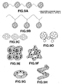
- the proton conductors shown in Figs.6A to 6M are a variety of carbon clusters, composed of a large number of carbon atoms and which are spherical, spheroidal or a similar shape presenting a closed face structure.
- molecular fullerene is also shown.
- Figs.7A to 7D show carbon clusters the spherical structure of which are partially lacking. These carbon clusters are featured by the presence of open ends in the structures thereof. These carbon clusters may be frequently seen as by-products in the production process of fullerene by arc discharge.
- Figs.7C to 7D the portions daubed all-over with black indicate five- or heptagonal rings.
- the carbon clusters the major portions of the carbon atoms of which are bonded by SP3 linkage, prove various clusters having the diamond structure shown in Figs.8A to 8G.
- the cluster has a graphitic planar structure, or a structure of part or all of fullerene or the nano-tube.
- many carbon clusters having the graphitic structure exhibit electron conductivity and hence is not desirable as the matrix of the proton conductor.
- the SP2 linkage of the fullerene or nano-tubes partially include the element of the SP3 linkage and hence does not exhibit electron conductivity in a majority of cases.
- the fullerene or nano-tube is desirable as the matrix of the proton conductor.
- Figs.9A to 9H show a variety of structures in which the clusters are bonded to one another. These structures may be used in the present invention.
- the present invention it is necessary to introduce the aforementioned proton dissociating groups into the carbon atoms forming the carbon cluster.
- the following manufacturing method may preferably be used.
- a carbon cluster formed by carbon powders, is produced by arc discharge of carbonaceous electrodes.
- This carbon cluster is acid-processed, using e.g. sulfuric acid, further hydrolyzed, further sulfonated or esterified with phosphoric acid, whereby a carbon cluster derivative as a targeted product may readily be produced.
- This carbon cluster derivative may directly be molded under pressure application to a membrane or to a pellet, without using a binder.
- the length of the long axis is preferably 100 nm or less, and more preferably 100D or less, while the number of the aforementioned groups, introduced to the carbon cluster, is desirably 2 or more.
- such a structured unit which has an open end in the basket-shaped structured unit, such as fullerene, or at least in a portion thereof.
- the fullerene of this defective structure exhibits the reactivity proper to fullerene, while the defective structure or the open structure exhibits a higher reactivity.
- the acid processing helps introduce proton dissociating substituents to achieve a higher substituent introducing rate and a higher proton conductivity.
- such fullerene of a defective structure can be synthesized at a lower cost in larger quantities than the normal fullerene.
- the structured unit of the tubular carbon is desirably tube-shaped, such as carbon nano-tube.
- the structured unit of the tubular carbon is desirably a fiber-shaped structured unit, such as carbon fibers.
- the carbon nano-tubes or carbon fibers are more liable to emit electrons, by reason of their structure, and can be appreciably increased in surface area, thus further improving the proton propagation efficiency.
- the carbon nano-tubes or carbon fibers may be manufactured by an arc discharge method or a chemical vapor deposition (thermal CVD).
- arc discharge method carbon may be deposited in the form of a cloth on the inner wall of a chamber by arc discharge by synthesis in a He atmosphere of e.g. 150 Torr, using an arc discharge chamber and metal catalysts, such as FeS, Ni or Co, to produce carbon nano-tubes. If the catalyst is used simultaneously, carbon nano-tubes of a finer diameter may be produced. On the contrary, if the arc discharge is carried out in the absence of a catalyst, carbon nano-tubes of a larger diameter may be produced.
- the carbon nano-tubes Cn can be produced by arc discharge in the absence of a catalyst, as discussed above.
- the graphene structure of the multi-layered carbon nano-tubes, shown in the perspective view of Fig.10A and in the fragmentary cross-sectional view of Fig.10B (cylindrical structure) is a defect-free high-quality carbon nano-tube Cn, and is known to be of an extremely high performance as being an electron emitting material.
- the chemical gas-phase growth method is a technique of reacting transition metals in a finely divided form with hydrocarbons, such as acetylene, benzene or ethylene, or CO, to synthesize carbon nano-tubes Cn or the carbon fiber Cf.
- the carbon nano-tubes Cn or the carbon fibers Cf are deposited on the substrate by reacting a substrate of a transition metal or a substrate coated with a transition metal with the hydrocarbon gas or with Co gas.
- a Ni substrate may be placed in an alumina tube, heated to 700EC, and reacted with a toluene/H 2 gas (such as 100 sccm) to synthesize the carbon fiber Cf, having a structure shown in a perspective view of Fig.10C.
- a toluene/H 2 gas such as 100 sccm
- the aspect ratio of the carbon nano-tube Cn is 1:1000 to 1:10, while that of the carbon fiber Cf is 1:5000 to 1:10. It is also preferred that the diameter of the structured unit of the tubular or linear carbon is 0.01 to 0.5 Fm, while the length thereof is 1 to 5 Fm.
- the pressurizing current controller 13 generates a voltage applied to the positive electrode side metal current collector 36 and to the negative electrode side metal current collector 37. It is noted that the higher the voltage generated by the pressurizing current controller 13, the higher is the pressure of the hydrogen gas in the negative electrode side gas reservoir chamber 39, as indicated by the above equation (3).
- An electro-chemical compression unit 40 in which fullerenol is used as the proton conductor 31 and in which the surface area of the MEA film was set to 12cm H 12cm, was prepared. A hydrogen gas was supplied to the surface of the positive electrode at a rate of 50 ml/min, and measurement was made of the time until the hydrogen gas pressure was raised to 10 atm, using the sensor for detecting the pressure of the hydrogen gas routed to the pressurizing unit.
- the theoretical value of the quantity of protons which have traversed the proton conductor 31 may be calculated, based on the current that has passed through the proton conductor 31, under the assumption that the totality of the current passed through the proton conductor 31 is by proton migration.
- the higher the hydrogen gas pressure the higher becomes the quantity of the hydrogen gas accumulated in the hydrogen gas tank in the charging unit 4.
- a higher pressurizing rate is preferred. If however the pressure is excessive, a larger pressure is applied to the proton conductor 31, thus raising a problem in connection with the pressure resistance of the proton conductor 31. It is therefore desirable to manage control to maintain a desirable pressurizing state at all times.
- the desirable state is such a one in which the pressure applied to the proton conductor 31 is controlled to be a value not larger than a preset value necessary for the charging unit 4 to be in operation.
- the specified controlling method is hereinafter explained.
- the pressure in the hydrogen gas pipe 41 for outputting the hydrogen gas to the pressurizing unit is equal to that in the negative electrode side gas reservoir chamber 39, so that this pressure may be detected by the hydrogen gas pressure sensor 42 for detecting the hydrogen gas pressure output from the pressurizing unit.
- the voltage generated by the pressurizing current controller 13 needs to be controlled to maintain the pressure applied to both surfaces of the proton conductor 31 to less than a preset pressure in order to protect the proton conductor 31.
- the atmospheric pressure applied to both sides of the proton conductor 31 is desirably kept to be 10 atm or less.
- This system controller 3 is responsive to the signals applied from the sensor 21 for detecting the hydrogen gas supplied to the pressurizing unit and the hydrogen gas pressure sensor 42, connected to the bus line 9, to calculate the difference between the pressure detected by the sensor 42 for detecting the hydrogen gas pressure output from the pressurizing unit and the pressure detected by the sensor 21 for detecting the hydrogen gas supplied to the pressurizing unit, in order to control the pressurizing current controller 13 over the bus line 9.
- the pressure detection units 60 to 68 and the hydrogen gas valves 70 to 78 are severally provided in association with the hydrogen gas tanks 50 to 58. It is not mandatory to provide the totality of the hydrogen gas tanks 50 to 58 at all times but it is only necessary to provide a desired number of the hydrogen gas tanks in the holder 12.
- the hydrogen gas may be charged into plural tanks simultaneously or sequentially. If tank characteristics differ from one hydrogen gas tank to another, it is necessary to control the charging pressure from tank to tank.
- Fig.12 shows occlusion characteristics of the hydrogen gas tank employing the hydrogen occlusion alloys of the LaNi 5 system.
- the hydrogen gas tanks 50 to 58 may be controlled in the following manner.
- the pressurizing current controller 13 to execute a pressurizing operation until the value of the pressure detection unit 60 is equal to a preset pressure which differs from one hydrogen gas tank to another, as long as the difference between the pressure detected by the hydrogen gas pressure sensor 42 and the pressure detected by the sensor 21 is within a preset pressure value.
- the preset pressure may be set to 10 atm in relationship to the hydrogen gas tank characteristics.
- the hydrogen gas valve 70 is closed, and the valve associated with the tank which has preserved the hydrogen gas is opened. In this manner, the hydrogen gas tanks may be charged sequentially.
- the operation of the pressurizing unit 2 may be halted, while the valve of the hydrogen gas tank may be closed at the same time as the operation of the pressurizing unit 2 is halted, in order to prevent destruction of the proton conductor 31, by way of completing the charging operation.
- the control signals for the above sequence of operations are calculated and sent by the system controller 3. Specifically, a tank pressure signal from the pressure detection unit 60 is sent to the charged state detection unit 6. The tank pressure signal is also sent to the system controller 3. This system controller 3 then calculates whether or not the tank pressure signal has reached a pressure predetermined from tank to tank. If the tank pressure is not up to the predetermined value, the system controller sends a signal for keeping the closed state of the hydrogen gas valve 70 to the valve signal generating unit 5 over bus line 9. The valve signal generating unit 5 then controls the hydrogen gas valve 70 to remain closed. When the tank pressure has reached a predetermined value, the system controller sends a signal for setting the closed state of the hydrogen gas valve 70 to the valve signal generating unit 5 over bus line 9. This valve signal generating unit 5 then controls the hydrogen gas valve 70 to its closed state.
- Fig.13 shows the flow of the operations performed by the system controller 3.
- the hydrogen gas manufacturing and charging apparatus compresses the low pressure hydrogen gas, generated in the electrolytic vessel 10, by the pressurizing unit 2, to charge the gas in a pressurized state to the hydrogen gas tanks 50 to 58.
- the pressurizing unit 2 to charge the gas in a pressurized state to the hydrogen gas tanks 50 to 58.
- only low pressure resistance characteristics of the casing 27 of the electrolytic vessel 10 suffices, so that it is possible to reduce the size and the weight of the electrolytic vessel 10, which hitherto had to be increased in order to hold a large quantity of the electrolytic solution 28.
- the proton conductor 31 is made up by a derivative mainly composed of at least one substance selected from the group consisting of fullerene molecules, a cluster mainly composed of carbon and a structured unit made up by tubular or linear carbon, and a proton dissociating group introduced into a carbon atom forming this substance, there is no necessity for humidification and hence there is no necessity for providing a humidifier. Moreover, the operation of performing a dehumidifying process prior to charging into the hydrogen gas tank, whilst a dehumidifier for preventing the alloy of the hydrogen gas tank from being deteriorated by oxidation is not needed, thus enabling the apparatus to be reduced in size.
- the present invention is directed to a hydrogen gas manufacturing and charging apparatus including a hydrogen gas pressurizing unit, composed of an electrochemical compression unit, having a first electrode arranged on the side supplying water in the state of steam or a gas for yielding a proton from water, a second electrode for converting the proton into a hydrogen gas to compress the hydrogen gas, and a proton conductor sandwiched between these two electrodes, and a pressurizing current controller for supplying the current corresponding to the pressurizing state of the electrochemical compression unit to the first and second electrodes.
- the hydrogen gas manufacturing and charging apparatus also includes a charging unit for charging the compressed hydrogen gas into a hydrogen gas tank.
- the hydrogen gas manufacturing and charging apparatus With the hydrogen gas manufacturing and charging apparatus according to the present invention, water in supplied to the first electrode in the form of steam or a gas to yield a proton, which then is moved to the second electrode through the proton conductor, so that the hydrogen gas may be manufactured and compressed easily efficiently, and hence a large quantity of hydrogen may be manufactured and compressed. Since this hydrogen gas manufacturing and charging apparatus may be of a small size and portable, such an apparatus may be provided which may be carried about by a user in person for manufacturing and charging the hydrogen gas extremely readily.
- the hydrogen gas tank may be taken out from the hydrogen gas manufacturing and charging apparatus according to the present invention for use in running a large variety of equipment powered by the hydrogen gas.
- the maintenance operations for the electrolytic solution for electrolysis may be dispensed with.
- the hydrogen gas manufacturing and charging apparatus may be run semi-permanently without maintenance operations.
- the surface of the first electrode not intimately contacted with the proton conductor is contacted with steam or steam-containing atmospheric air, and that the hydrogen gas is generated and compressed on the second electrode.
- the hydrogen gas pressurizing unit and the charging unit are controlled by the system controller, there is provided a hydrogen gas pressure detection means for detecting the hydrogen gas pressure on the hydrogen gas outputting side of the pressurizing unit, and that, when the signal from the hydrogen gas pressure detection means has indicated a predetermined pressure, the operation of the pressurizing unit is halted or the hydrogen gas tank to be charged with the hydrogen gas is switched to another tank.
- Fig.14 depicts a schematic structure of this modification of the hydrogen gas manufacturing and charging apparatus of the present invention.
- the present hydrogen gas manufacturing and charging apparatus directly takes out the hydrogen gas from the moisture in air, compresses the so taken out hydrogen gas to charge the so compressed hydrogen gas into the hydrogen gas tank without the intermediary of the electrolytic process by the dedicated electrolytic vessel.
- the positive electrode side gas reservoir chamber 38 is opened to air such that air carrying the moisture is circulated by convection therethrough at all times. This air convection may be promoted by providing e.g. a fan as necessary.
- a power supply unit 43 is responsible for supplying the power to the entire apparatus.
- the power supply device may e.g. be a commercial power supply. If the apparatus is used outdoors, the power supply unit may be a battery or a combination of the battery and the solar power generating unit.
- the current of 12 mA was passed through a positive electrode 32 and a negative electrode 33, in an atmosphere with the humidity of 70%, as air with humidity of 50% was supplied to the surface of the positive electrode side electrode 32 at a rate of 50 ml/min.
- On the surface of the positive electrode 32 water is decomposed into oxygen and proton, with the proton being transported towards the negative electrode 33 under the effect of the applied voltage.
- the proton which has received electrons on the negative electrode 33 is re-converted into a hydrogen gas, which is preserved in the negative electrode side gas reservoir chamber 39 to raise the internal pressure.
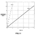
- Fig.15 shows measured results of the internal pressure of the negative electrode side gas reservoir chamber 39 when the hydrogen gas pipe 41 for outputting the hydrogen gas to the pressurizing unit is closed.
- the pressure of the hydrogen gas manufactured on decomposition of water increased to 2.5 atm in twelve hours. Since the capacity of the negative electrode side gas reservoir chamber 39, in which the hydrogen gas has been compressed, is 24 ml, the compressed hydrogen gas of 60 ml was preserved therein. If the hydrogen gas pipe 41 for outputting the hydrogen gas to the pressurizing unit is in an opened state, the hydrogen gas is charged into one of the hydrogen gas tanks 50 to 58, for example, into the hydrogen gas tank 50. Except if the humidity is 0%, the higher the humidity, the more is theoretically the quantity of the manufactured hydrogen gas.
- the operation of electrolysis and pressurizing for charging is discontinued and, based on a signal from the valve signal generating unit 5, the hydrogen gas valve 70 provided on the hydrogen gas tank side is closed. This completes the charging operation.
- hydrogen may be manufactured from steam or from the steam-containing atmospheric air, while the electrolytic solution is not used, so that maintenance is unneeded. If the power of the electrical unit, such as the controller, is supplied from the natural energy, such as by solar power generation or wind power generation, the hydrogen gas can be continuously supplied by unmanned equipment. If the hydrogen gas manufacturing and charging apparatus is combined with an apparatus adapted for automatically supplying the hydrogen gas to a fuel cell, unmanned operation of an apparatus powered by a fuel cell becomes possible.
- the proton conductor 31 is made up by a derivative mainly composed of at least one substance selected from the group consisting of fullerene molecules, a cluster mainly composed of carbon and a structured unit made up by tubular or linear carbon, and a proton dissociating group introduced into a carbon atom forming this substance, and the proton generated in the first electrode 32 may be moved to the second electrode 33 through this proton conductor 31, so that the hydrogen gas manufacturing and charging apparatus may be run in atmospheric air satisfactorily.
- hydrogen may be manufactured and compressed efficiently without the necessity of adjustments for pressure, temperature or humidity at the time of hydrogen production and compression.
- the hydrogen gas manufacturing and charging apparatus may be run even in atmospheric air in the low humidity state, even in the absence of e.g. a humidifying apparatus. That is, since hydrogen may be manufactured and compressed in atmospheric air in the low humidity state, the initial operation at the time of hydrogen production and compression can be accelerated without taking much time until a steady-state running state is achieved.
- a humidifying device may be provided and the moisture may be present for hydrogen production and compression, this is not comprised within the scope of the present invention.
- water is yielded with hydrogen production and compression, so that a dehumidifier is needed.
- water is supplied as steam or a gas to the positive electrode 32 for electrolysis and protons so generated are moved through e.g. the proton conductor 31, formed e.g. of fullerenol, to the negative electrode 33, where the proton is converted into hydrogen and compressed, so that production and compression only of hydrogen may be enabled even in the absence of e.g. a dehumidifier.
- the moisture content of the compressed hydrogen gas is only small. Consequently, the dehumidification process as a post-processing is not needed, so that the hydrogen gas may be directly sent to the charging unit 4.
- the present invention is directed to an electrochemical apparatus including an electrolytic unit for evolving the hydrogen gas by electrolysis, a pressurizing unit for compressing the hydrogen gas generated in the electrolytic unit, and a charging unit for charging the compressed hydrogen gas into a hydrogen gas tank, in which the pressurizing unit is configured for operating as a fuel cell unit which may be run reversibly by being supplied with the hydrogen gas from the charging unit and with oxygen or an oxygen containing gas.
- the electrochemical apparatus is designed and constructed so that the pressurizing unit operates for compressing the hydrogen gas evolved in the electrolytic unit, while it is designed and constructed as a fuel cell unit which may be run reversibly by being supplied with the hydrogen gas from the charging unit and with oxygen or an oxygen containing gas, so that the power from the fuel cell employing the hydrogen gas may be obtained by the same apparatus as generates and compresses the hydrogen gas.
- the apparatus may be further reduced in size because the pressurizing action and the action as the fuel cell are of the same structure, to add to the favorable effect that the power is transformed for the time being into a hydrogen gas and the power may be produced from the hydrogen gas at an optional later time.
- a useful application may be contemplated, in which the hydrogen gas is manufactured and charged with the night time power, and the apparatus is taken outdoors during the daytime for use as a fuel cell.
- the electrochemical apparatus is preferably designed and constructed so that the pressurizing unit is made up by an electrochemical compressing unit and a pressurizing current controller, the electrochemical compressing unit is made up by a first electrode for decomposing the hydrogen gas into protons, a second electrode for re-converting the proton, generated in the first electrode, into a hydrogen gas, and a proton conductor sandwiched between these two electrodes, with the pressurizing current controller supplying the current corresponding to the pressurizing state of the pressurizing unit to the first and second electrodes.
- a catalyst layer preferably is provided on both surfaces of the proton conductor.
- the electrochemical apparatus according to the present invention is preferably designed and constructed so that the electrolytic unit, the pressurizing unit or the fuel cell unit and the charging unit are controlled by the system controller, which system controller also selects the operation of the compressing the hydrogen gas by the pressurizing unit or the operation as the fuel cell unit.
- the electrochemical apparatus includes a hydrogen pressure detection means for detecting the hydrogen pressure on the hydrogen gas outputting side of the pressurizing unit and, when a signal from the hydrogen pressure detection means indicates a predetermined pressure, the operation of the pressurizing unit is halted, or the hydrogen gas tank charged with the hydrogen is switched to another tank.
- Fig.16 schematically shows the structure of the electrochemical apparatus according to the present invention.
- a hydrogen gas is generated by the electrolytic unit 1 and generated hydrogen gas is compressed by the pressurizing unit 2 and the so compressed hydrogen gas is charged to the hydrogen gas tank 50.
- the hydrogen gas is taken out from the hydrogen gas tank 50 and the electro-chemical compression unit 40 as the fuel cell unit is run by the hydrogen gas.
- the electro-chemical compression unit 40 may directly operate as the aforementioned fuel cell unit so that the pressurizing unit 2 may directly be used as the fuel cell.
- a charging supplying unit 34 not only charges the hydrogen gas into the hydrogen gas tank, but also supplies the hydrogen gas from the hydrogen gas tank to the fuel cell unit.
- a hydrogen gas valve 81 for the hydrogen gas supplied to the pressurizing unit is closed, while an air valve 19 is opened to send air from an air supplying unit 15 into the positive electrode side gas reservoir chamber 38.
- the air supplying unit 15 may be a usual fan or simply an air hole for taking in outside air.
- An air ventilating valve 82 is opened to ventilate air so that oxygen will be sufficiently circulated to prevent the nitrogen concentration from increasing excessively.
- An output switching unit 18 is constructed by e.g. a relay.
- the pressurizing unit 2 operates as a fuel cell unit, the power generated by the pressurizing unit 2 is supplied to an output connector 17.
- the above-described control is managed on the basis of signals from the system controller 3.
- the output switching unit 18 disconnects the output connector 17 and the pressurizing unit 2 from each other, such that the hydrogen gas valve 81 for the hydrogen gas supplied to the pressurizing unit is opened, while the air valve 19 and the ventilating valve 82 are closed.
- the hydrogen gas tank, fuel cell unit and the pressurizing unit can be co-owned by the hydrogen gas manufacturing and charging mechanism and the fuel cell mechanism, and hence the electrochemical apparatus can be reduced in size.
- the hydrogen gas may be charged into the tank during nighttime and, in outing, a user may carry it outdoors for use as a battery.
- the hydrogen gas bottle may be taken out and used as a common hydrogen gas manufacturing and charging apparatus.
- electro-chemical compression unit 40 may be run satisfactorily in atmospheric air, hydrogen may be manufactured or the power may be generated efficiently without the necessity of making adjustments for pressure, temperature or humidity at the time of hydrogen production and compression.
- the electrochemical apparatus 300 of the present invention may be run satisfactorily even in atmospheric air of low humidity, in distinction from the case of using Nafion as H 3 O + ion. That is, hydrogen may be compressed or the power may be generated in atmospheric air of low humidity, so that the initial operation at the time of hydrogen production and compression can be accelerated without taking much time until a steady-state running state is achieved.
- a humidifying device may be provided and the moisture may be present for hydrogen production and compression, this is not comprised within the scope of the present invention.
- the moisture content of the compressed hydrogen gas is only small. Consequently, the dehumidification process as a post-process is not needed, so that the hydrogen gas may be directly sent to the charging unit 4.
- the present invention is directed to still another electrochemical apparatus including a hydrogen gas pressurizing unit and a charging unit.
- the hydrogen gas pressurizing unit is made up by an electrochemical compressing unit composed of a first electrode arranged on the water supply side supplying water as steam or in a gaseous state for generating a proton, a second electrode for converting the proton into a hydrogen gas and compressing the so produced hydrogen gas, and a proton conductor sandwiched between these two electrodes, and a pressurizing current controller for supplying the current corresponding to the pressurizing state of the electrochemical compression unit to the first and second electrodes.
- the charging unit charges the compressed hydrogen gas to the hydrogen gas tank.
- the hydrogen gas pressurizing unit of the electrochemical apparatus plays the role of a fuel cell unit which may be run reversibly by being supplied with the hydrogen gas from the charging unit and with oxygen or an oxygen-containing gas.
- the electrochemical apparatus according to the present invention is designed and constructed so that the pressurizing unit operates for compressing the hydrogen gas evolved in the electrolytic unit and as a fuel cell unit which may be run reversibly by being supplied with the hydrogen gas from the charging unit and with oxygen or an oxygen containing gas, so that the power from the fuel cell employing the hydrogen gas may be obtained by the same apparatus as generates and compresses the hydrogen gas.
- the apparatus may be further reduced in size because the pressurizing action and the action as the fuel cell are of the same structure, to add to the favorable effect that the power is transformed for the time being into a hydrogen gas and the power may be produced from the hydrogen gas at an optional later time.
- a useful application may be considered, in which the hydrogen has is manufactured and charged with the night time power, and the apparatus is taken outdoors during the daytime for use as a fuel cell.
- the electrochemical apparatus is preferred that a catalyst layer is provided on each of both surfaces of the proton conductor, and that the surface of the first electrode not intimately contacted with the proton conductor is contacted with steam or with steam-containing atmospheric air, with hydrogen being generated and compressed on the second electrode side.
- the electrochemical apparatus according to the present invention is preferably designed and constructed so that the hydrogen gas pressurizing unit or the fuel cell unit and the charging unit are controlled by the system controller, which system controller also selects the operation of compressing the hydrogen gas by the hydrogen gas pressurizing unit or the operation of the fuel cell unit.
- the electrochemical apparatus includes a hydrogen pressure detection means for detecting the hydrogen pressure on the hydrogen gas outputting side of the pressurizing unit and, when a signal from the hydrogen pressure detection means indicates a predetermined pressure, the operation of the pressurizing unit is halted, or the hydrogen gas tank charged with the hydrogen is switched to another tank.
- a second fuel cell unit which may be run reversibly by being supplied with the hydrogen gas from the charging unit, and with oxygen or the oxygen-containing gas, may be provided, and the electrochemical energy may be taken out from this second fuel cell unit. It is preferred that there is provided valving means for controlling the amount of the hydrogen gas supplied from the charging unit to the second fuel cell unit, and that the system controller controls the operation and/or the outputting of the second fuel cell unit or detects the outputting.
- the second fuel cell unit is constructed independently of the pressurizing unit, so that any optional voltage may be produced.
- Fig.17 schematically shows the structure of a fuel cell apparatus 400 in which a second fuel cell unit is provided to the electrochemical apparatus according to the present invention.
- the hydrogen gas is generated by the electrolytic unit 1, the generated hydrogen gas is compressed by the pressurizing unit 2 and the so compressed hydrogen gas is charged to the hydrogen gas tank 50. Or, the hydrogen gas is taken out from the hydrogen gas tank 50 and the electro-chemical compression unit 40 as the fuel cell unit is run by the hydrogen gas. It is noted that the hydrogen gas is supplied to the second fuel cell unit 14 by the hydrogen gas tank 50 or 51. For example, as the hydrogen gas is supplied from the pressurizing unit 2 to the hydrogen gas tank 50, the hydrogen gas may be supplied to the fuel cell unit 14 to effect hydrogen manufacture and power generation simultaneously.
- the air supplying unit 15, which furnishes air (oxygen or an oxygen-containing gas) to the second fuel cell unit 14, may, for example, be a usual fan.
- a voltage converter 16 which converts the power from the second fuel cell unit 14 into a predetermined voltage, may convert the voltage not only into the D.C. but also into A.C. such that it may be a switching regulator or an inverter.
- the power from the voltage converter 16 is supplied via output connector 17 to a unit outside the apparatus as the power used therein.
- the present electrochemical apparatus may be put to a still broader use in addition to the use as the hydrogen gas manufacturing and charging apparatus according to the above-described still further aspect of the present invention.
- the power supply may be not only the commercial power supply for household use, but also any suitable power supply without regard to the configuration of the power generation, such as wind power generation, solar power generation, geothermal power generation, biomass power generation, wave force power generation, exemplified by tidal sea water power generation, artificial power generation, secondary batteries, such as car batteries, or primary batteries, such as dry cell.
- the electrolytic unit 1 may be of the type in which the electrodes are provided in the electrolytic solution, such as the type in which sulfuric acid or alkali hydroxide is used as an electrolytic solution, or of the type in which a solid high molecular electrolytic film is used and pure water is supplied to the positive electrode side.
- the number of the hydrogen tanks, provided to the charging unit, may be arbitrary, while the sort of the hydrogen gas tank may be arbitrary, such that a hollow high pressure tank, a hydrogen gas occlusive alloy, a hydrogen gas occlusive carbonaceous material or a hydrogen gas occlusive tank, the inside of which is filled with metal halides, may be used.
- the hydrogen gas occlusive alloy may be exemplified by LaNi 5 , CaNi 5 , TiCo0.5Mn0.5, TiCo0.5Fe0.5 and TiFe0.8Ni0.15V0.05.
- the hydrogen gas occlusive carbonaceous material may be exemplified by carbon nano-tubes, carbon fibers or activated charcoal, while the metal halides may be exemplified by NaAlH 4 and LiAlH 4 .
- the system controller 3 may be provided in a concentrated form, or part or all functions thereof may be provided distributed in the electrolytic unit, pressurizing unit or in the charging unit.
- the system controller may be formed by a CPU or by a hardware.
- the system controller 3 may be configured for detecting or controlling the fuel cell unit 14, as indicated by a broken line in Fig.17.
- the hydrogen gas manufacturing and charging apparatus includes an electrolytic unit for evolving the hydrogen gas by electrolysis and hence is able to manufacture a hydrogen gas readily efficiently.
- This apparatus includes a pressurizing unit and a charging unit and hence is able to compress and charge a large quantity of hydrogen efficiently. Moreover, it may be reduced in size and portable and hence may be designed as an apparatus that may be carried by a user in person for manufacturing and charging the hydrogen gas extremely readily.
- a large variety of equipment run on the hydrogen gas may be in operation, as a result of which the fuel cell having the hydrogen gas as an active material may readily be put to personal use.
- the hydrogen gas manufacturing and charging apparatus in which there is provided an electrochemical compressing unit for supplying water as steam or in a gaseous form to the first electrode to yield a proton thereat, causing movement of the so generated proton through a proton conductor to the second electrode, where the generated proton is converted to hydrogen and the so generated hydrogen is compressed, the hydrogen gas may be manufactured and compressed readily efficiently, such that a large quantity of hydrogen may be compressed and charged efficiently.
- the hydrogen gas in which the hydrogen gas is yielded from the moisture in air so as to be then compressed and charged in the hydrogen gas tank, maintenance for e.g. an electrolytic solution in electrolysis may be omitted.
- the power supply necessary for operation of the equipment is obtained from the energy available from nature, it is possible to provide a hydrogen gas manufacturing and charging apparatus which may be run semi-permanently without the necessity for maintenance.
- the pressurizing unit operates for compressing the hydrogen gas evolved in the electrolytic unit and is configured for operating also as a fuel cell unit operable reversibly on being supplied with a hydrogen gas from the charging unit and with oxygen or an oxygen-containing gas
- the power from the fuel cell exploiting the hydrogen gas may be obtained with the same apparatus as that configured for manufacturing and charging the hydrogen gas.
- the apparatus may be reduced in size, because the pressurizing action and the action as a fuel cell are of the same structure, to add to the favorable effect that a sole apparatus may be used for converting the power once into a hydrogen gas and the power may then be recovered from the hydrogen gas at an optional later time.
- the present electrochemical apparatus such a useful application may be contemplated, in which the hydrogen has is manufactured and charged with the night time power, and the apparatus is taken outdoors during the daytime for use as a fuel cell.
Landscapes
- Chemical & Material Sciences (AREA)
- Electrochemistry (AREA)
- Engineering & Computer Science (AREA)
- Chemical Kinetics & Catalysis (AREA)
- Manufacturing & Machinery (AREA)
- Life Sciences & Earth Sciences (AREA)
- Sustainable Development (AREA)
- Sustainable Energy (AREA)
- General Chemical & Material Sciences (AREA)
- Materials Engineering (AREA)
- Metallurgy (AREA)
- Organic Chemistry (AREA)
- Inorganic Chemistry (AREA)
- Electrolytic Production Of Non-Metals, Compounds, Apparatuses Therefor (AREA)
- Fuel Cell (AREA)
Abstract
The present invention is relative with an electrochemical apparatus including a hydrogen manufacturing and preserving device capable of manufacturing hydrogen and compressing and charging the so manufactured hydrogen. The apparatus includes an electrolytic unit (1) for generating a hydrogen gas on electrolysis, a pressurizing unit (2) for compressing the hydrogen gas generated by the electrolytic unit (1) and a charging unit (4) for charging the compressed hydrogen gas to the hydrogen gas tanks (50 to 58). The pressurizing unit (2) operates as a fuel cell unit run reversible on being supplied with the hydrogen gas from the charging unit (4) and with oxygen or an oxygen-containing gas. <IMAGE>
Description
This invention relates to an apparatus for manufacturing and charging
hydrogen gas and electrochemical apparatus.
A fuel cell, employing a hydrogen gas as an electrode active material, has
been offered. The fuel cell is stirring up notice as being a source energy imposing
only a low load on the environment. From the technological perspective, how to
generate and preserve a hydrogen gas is crucial in order for the fuel cell to become
popular.
It may be premeditated that, in future, the hydrogen gas will be in
widespread use, such that the gas may be delivered directly to households and
become readily available. For generating the hydrogen gas, the method by
electrolysis of water is predominantly used.
As the technique for preserving the hydrogen gas, a method for preserving
the hydrogen gas, compressed to a high pressure, in a high-pressure vessel, or a
method of using a hydrogen gas occluding alloy, is used. It is noted that, whether
the hydrogen gas is preserved in a high pressure vessel, or a hydrogen gas
occluding alloy is used, the quantity of the preserved hydrogen gas becomes larger
if the hydrogen gas is compressed to a higher pressure. Thus, the technique of
compressing and preserving the hydrogen gas is crucial.
This method has a drawback that the apparatus tends to be increased in size,
such that, in order for a user to generate and utilize the hydrogen gas readily for
personal use, the conventional method of applying a mechanical pressure is not
proper.
As a method for compressing the hydrogen gas in a manner free of this
inconvenience, an electro-chemical gas compression apparatus has been proposed
in US Patent 4671080 and in Japanese Laying-Open Patent Publication
H-5-242850.
Fig.1 shows a conventional electro-chemical hydrogen gas compressor
disclosed in the US Patent 4671080. Referring to Fig.1, 201 denotes a film of e.g.
a perfluorosulfonate resin, as an ionic conduction film, having a thickness of
approximately 0.2 mm, 202 denotes an electrode for gas diffusion, operating as a
positive electrode, carrying a catalyst of e.g. platinum, 203 denotes an electrode for
gas diffusion, operating as a negative electrode, carrying a catalyst similar to the
catalyst carried by the positive electrode 202, 204 denotes a positive electrode side
gas flow channel, 205 denotes a negative electrode side gas flow channel, 206
denotes a positive electrode side metallic current collector, and 207 denotes a
negative electrode side metallic current collector. As this perfluorosulfonate resin,
Nafion 117, manufactured by Du Pont (Inc.) (referred to below as Nafion), is used.
The operating principle of this apparatus is now explained. When the
hydrogen gas is supplied to a gas flow channel 204 on the side of the electrode for
gas diffusion 202, this hydrogen gas loses an electron on the gas diffusion electrode
202, to yield H3O+ ions, in accordance with the following formula (1):
H2 + 2H2O → 2e- + 2H3O+
This 2H3O+ ion, thus yielded, proceeds to the opposite side electrode for gas
diffusion 203, with the voltage as a driving power, as it entrains water in the film of
ionic conduction 201, to accept electrons on this electrode for gas diffusion 203, so
as to be re-converted to a hydrogen gas in accordance with the following formula
(2):
2e- + 2H3O+ →H2 + 2H2O
The hydrogen gas, yielded on the electrode for gas diffusion 203, cannot pass
through the film of ionic conduction 201 and, moreover, the force of movement of
the ions by the voltage is large, so that the hydrogen gas is gradually accumulated
on the side of the electrode for gas diffusion 203, thus raising the pressure of the
hydrogen gas. At this time, metal current collectors 206, 207 apply the voltage
across the electrodes for gas diffusion 202, 203, while mechanically augmenting the
electrodes for gas diffusion 202, 203 and ionic conduction film 201.
With the invention described in the Japanese Laying-Open Patent Publication
H-5-242850, it is stated therein that the object of the invention described therein is
to provide an electro-chemical gas compression apparatus having high mechanical
reliability and superior electronic characteristics and which moreover is lightweight,
compact and is capable of developing a large output.
That is, there is the following statement in the Japanese Laying-Open Patent
Publication H-5-242850:
The conventional electro-chemical gas compression apparatus is arranged
and constructed as set forth above, and the voltage applied across the electrodes for
gas diffusion 202, 203 is as indicated by the following equation (3):
E = E0 + (RT/2F) × ln(P2 /P1 ) + ir
where E0 is the ionizing potential of the hydrogen gas, R is a gas constant, T is
temperature, F is a Faraday constant, P1 is the hydrogen gas pressure on the side of
the electrode for gas diffusion 202, P2 is the hydrogen gas pressure on the side of
the electrode for gas diffusion 203, i is the current and r is an electrical resistance.
As for details of the voltage applied across the electrodes 202, 203, the
ionizing potential E0 of the first term of the right side is 0.02 V, and the second term
is the so-called Nernst's additive voltage. This additive voltage, which is
determined by the gas pressure across the two electrodes 202, 203, is 0.06 V even
when the gas pressure is compressed to 100 atm.
However, even with the current on the order of 400 mA/cm2, the resistance
of the third term is large and is 0.1V, accounting for 55% of the entire voltage.
That is, the proposed compressor suffers from a drawback that the voltage
efficiency of the compressor is extremely small because of the large electrical
resistance of the ionic conduction 201 film.
The resistance of the film of ionic conduction 201 is that in case its thickness
is approximately 0.2 mm. Thus, for reducing the electrical resistance of the film
of ionic conduction 201, it is sufficient to reduce its film thickness. There is also
such a method in which a sufficient quantity of moisture is supplied to the film of
ionic conduction 201 to maintain the ionic conductivity of the film of ionic
conduction 201. In this method, there is, however, such a problem that, when
H3O+ ions migrate through the film, the moisture is thereby moved, so that, if the
current is small, the moisture on the negative electrode 203 is returned back to the
positive electrode 202 by reversal through the film 201, by diffusion, with the
consequence that it is difficult to cause the current to flow continuously unless
water is separately supplied.
For ameliorating this problem, the Japanese Laying-Open Patent Publication
H-5-242850 discloses an arrangement in which a plural number of solid electrolytes
exhibiting ionic conductivity and a plural number of electrodes exhibiting gas
diffusion characteristics are layered alternatively to provide plural cells of a unitary
structure, an arrangement in which a moisture supplying channel for supplying the
moisture is provided to the gas diffusion electrodes characteristics provided
between neighboring cells, and an arrangement in which an external electrical
circuit is connected to the gas diffusion electrodes provided between neighboring
cells to provide for variable voltages applied across plural electrodes.
With the respective apparatuses, disclosed in the above-mentioned Japanese
Laying-Open Patent Publication H-5-242850, it is necessary to provide a moisture
supplying channel for supplying the moisture to the gas diffusion electrode
positioned between the respective unit cells, while it is also necessary to install an
external pump to supply the moisture, with the consequence that the apparatus is
unavoidably increased in size.
It is therefore an object of the present invention to provide a novel hydrogen
gas manufacturing and charging apparatus and a novel electrochemical apparatus
whereby it is possible to dissolve the problem inherent to the above-described
conventional apparatus.
It is another object of the present invention to provide a hydrogen gas
manufacturing and charging apparatus and an electrochemical apparatus which are
simple in structure, small in size and and which are able to manufacture hydrogen
easily and compress/charge hydrogen efficiently.
For accomplishing the above objects, the present invention provides a
hydrogen gas manufacturing and charging apparatus comprising an electrolytic unit
for generating a hydrogen gas by electrolysis, a pressurizing unit for compressing
the hydrogen gas evolved in the electrolytic unit, and a charging unit for charging
the hydrogen gas compressed by the pressurizing unit into a hydrogen gas tank.
By having the electrolytic unit for generating the hydrogen gas on
electrolysis, the hydrogen gas charging apparatus is able to manufacture the
hydrogen gas readily efficiently. Moreover, by having the pressurizing unit and
the charging unit, the hydrogen gas charging apparatus is able to compress and
charge hydrogen efficiently.
The hydrogen gas charging apparatus of the present invention can be reduced
in size and made portable, so that it can be carried by a user in person to
manufacture and charge the hydrogen gas extremely readily. If the hydrogen gas
tank is taken out for use, it may be used for running a variety of apparatus powered
by the hydrogen gas.
It is preferred that, with the hydrogen gas manufacturing and charging
apparatus according to the present invention, the pressurizing unit is made up by an
electrochemical compressing unit for electrochemically compressing the hydrogen
gas, and a pressurizing current controller, and the electrochemical compressing unit
is made up by a first electrode for decomposing the hydrogen gas into protons (H+)
and a second electrode for re-converting the protons generated in the first electrode
into the hydrogen gas and a proton conductor sandwiched between these electrodes,
the pressurizing current controller supplying the current corresponding to the
pressurizing state of the pressurizing unit to the first and second electrodes.
It is also preferred that, with the hydrogen gas manufacturing and charging
apparatus according to the present invention, the electrolytic unit, pressurizing unit
and the charging unit are controlled by a system controller.
Other objects, features and advantages of the present invention will become
more apparent from reading the embodiments of the present invention as shown in
the drawings.
Referring to the drawings, a hydrogen gas manufacturing and charging
apparatus and an electro-chemical gas compression apparatus, according to the
present invention, are explained in detail.
A hydrogen gas manufacturing and charging apparatus 100, according to the
present invention, is roughly composed of an electrolytic unit 1, a pressurizing unit
2, a system controller 3 and a charging unit 4, as shown in Fig.2.
The electrolytic unit 1 includes a transforming rectifying unit 7, an
electrolysis controller 8, an electrolytic vessel 10 and an electrolysis state detection
unit 11.
An input terminal 20 of the transforming rectifying unit 7 is connected to a
power supply, not shown. The power supply may be any suitable power supply,
such as, for example, a commercial power supply or a power generator exploiting
natural energy. As the commercial power supply, a usual home uses A.C. 100V or
a larger power supply of A.C. 200V.
The transforming rectifying unit 7 is made up by a transformer, a rectifier
and a smoothing capacitor, not shown, for producing a D.C. power of a voltage
required for electrolysis. For these, a switching regulator, for example, is
substituted in case a D.C. power supply is used as a power supply. An output end
of the D.C. power of the transforming rectifying unit 7 is connected to an input end
of the electrolysis controller 8.
The electrolysis controller 8 controls the amount of the hydrogen gas evolved
by electrolysis, and has its control voltage output ends 22, 23 directly connected to
respective electrodes 24, 25 provided to the electrolytic vessel 10.
The electrolytic vessel 10 is made up by electrodes 24, 25, a gas separating
film 26, a casing 27 for holding an electrolytic solution 28, the electrolytic solution
28, a liquid level sensor 29 for sensing the surface state of the electrolytic solution
and a hydrogen gas pipe 30 for conducting the hydrogen gas yielded in the
electrolytic vessel 10 to the pressurizing unit 2. Meanwhile, the inside of the
casing 27 is divided by a gas isolation film 26 into two spacings, such that the
hydrogen gas evolved on the electrode 25 by the operation of the electrolysis is
passed to the pressurizing unit 2 through the hydrogen gas pipe 30 for supplying the
hydrogen gas supplied to the pressurizing unit.
The hydrogen gas pipe 30 for hydrogen supplied to the pressurizing unit
includes a sensor 21 for detecting the hydrogen gas supplied to the pressurizing unit.
The sensor 21 for detecting the hydrogen gas supplied to the pressurizing unit may,
for example, be a pressure detecting apparatus employing a diaphragm, and
converts the displacement of the diaphragm corresponding to the pressure into
electrical signals.
To the electrolysis state detection unit 11 is coupled an output signal from
the liquid level sensor 29 and the sensor 21 for detecting the hydrogen gas supplied
to the pressurizing unit. The electrolysis state detection unit is further connected
to the system controller 3 over a bus line 9.
The pressurizing unit 2 is made up by an electro-chemical compression unit
40 and a pressurizing current controller 13.
The electro-chemical compression unit 40 is made up by a gas diffusion
electrode 32 of a positive electrode, as a first electrode, carrying a catalyst of e.g.
platinum, a gas diffusion electrode 33 of a negative electrode, as a second electrode,
carrying a catalyst of e.g. platinum, a proton conductor 31, sandwiched between
these electrodes, a positive electrode side metal current collector 36, a negative
electrode side metal current collector 37, a positive electrode side gas reservoir
chamber 38 and a negative electrode side gas reservoir chamber 39. That is, the
electro-chemical compression unit includes a multi-layered film comprised of a
membrane (thin film) and electrodes (membrane and electro-assembly) in which the
membranous proton conductor 31 is sandwiched between the positive electrode 32
and the negative electrode 33.
Preferably, the proton conductor 31 has a thickness of e.g. approximately
0.03 mm and includes a catalyst layer on each side thereof. By providing the
catalyst layer, it is possible to improve electro-chemical decomposition of hydrogen
to improve the proton yielding efficiency further.
The gas diffusion electrodes 32, 33 are preferably heat-resistant and of a
surface area which is as large as possible. The gas diffusion electrodes 32, 33 may
also preferably be intimately bonded over their entire surfaces to the proton
conductor 31 through a catalyst carried on their surfaces and exhibit flexibility to a
certain extent for bonding to the proton conductor 31. The gas diffusion
electrodes 32, 33 are also preferably activated electrodes.
In light of the foregoing, the positive electrode 32 and the negative electrode
33 are porous or meshed. For example, the positive electrode and the negative
electrode may each be manufactured by forming carbon fibers or porous carbon as a
starting material into a sheet and by having an active catalyst carried by the surface
of the sheet intimately bonded to the proton conductor 31. A net-shaped member,
as a core material, obtained on knitting a metal wire, may be inserted in or bonded
to the sheet-shaped electrode material. By inserting or bonding the metal core
material in this manner, the electrode itself may be improved in electrical
conductivity, such that uniform current distribution may be expected to be achieved
over the entire electrode surface.
The catalyst is preferably fine particles of e.g. platinum, ruthenium oxide or
iridium oxide. Any other suitable electrode material, such as silver, may also be
used provided the targeted reaction is allowed to take place with the electrode
material used.
The catalyst used may be carried on the electrodes 32, 33 by any usual
method. For example, such a method may be used which consists in having a
catalyst material or a precursor thereof carried on the surfaces of carbon particles
and heating the resulting mass to form catalyst particles which may then be sintered
on the electrode surface along with the fluorine resin. With this method, an
electrode carrying no catalyst material is prepared at the outset, and a precursor of
the catalyst material, such as a mixed aqueous solution of chloroplatinic acid and
chlororuthenic acid, or a butyl alcohol solution, as a coating solution, is coated on
the electrode surface, and the resulting mass is sintered at 200 to 350°C in a
hydrogen-containing reducing atmosphere, to form a platinum-ruthenium alloy on
the electrode surface.
The electro-chemical compression unit 40 may also be formed by alternately
forming a proton conductor and a gas diffusing electrode a number of times, as
shown in Fig.3, whereby a higher compression ratio may be obtained extremely
readily.
The hydrogen gas, compressed by the electro-chemical compression unit 40,
is supplied through a hydrogen gas pipe 41 for outputting the hydrogen gas to the
aforementioned hydrogen gas tank mounted in a hydrogen gas tank holding unit 12
in the charging unit 4. In this hydrogen gas pipe 41, there may be mounted a
hydrogen gas pressure sensor 42 for detecting the pressure of the compressed
hydrogen gas. The hydrogen gas pressure sensor 42 may be of the routinely used
diaphragm type.
The positive electrode side gas reservoir chamber 38 and the negative
electrode side gas reservoir chamber 39 may be provided with a gas discharge port,
not shown, for discharging an extremely small amount of a gas at all times or at a
specified timing for purging a mixed gas component other than the hydrogen gas.
The charging unit 4 is made up by a hydrogen gas tank holding unit 12, a
charged state detection unit 6 and a valve signal generating unit 5. The hydrogen
gas tank holding unit 12 is provided with hydrogen gas tanks 50 to 58. Although
Fig. 1 shows a case wherein nine of the aforementioned hydrogen gas tanks are
arranged, there is no limitation to the number of the hydrogen gas tanks, such that
one or any desired plural number of the hydrogen gas tanks may be used.
The hydrogen gas tanks 50 to 58 and the and the electro-chemical
compression unit 40 are interconnected through the hydrogen gas pipe 41 of the
pressurizing unit 2, pressure detection units 60 to 68 and hydrogen gas valves 70 to
78. The pressure detection units 60 to 68 may be pressure detection devices,
employing routinely used diaphragms, and convert the diaphragm displacement
corresponding to the pressure into electrical signals.
The charged state detection unit 6 is supplied with pressure signals from the
pressure detection units 60 to 68.
The hydrogen gas valves 70 to 78, controlling the flow of the hydrogen gas
from the hydrogen gas pipe 41, may be configured as electro-magnetic valves
producing two states, that is an opened state and a closed state, of an
electro-magnetic valve.
The valve signal generating unit 5 outputs independent control signals for the
respective ones of the hydrogen gas valves 70 to 78.
The hydrogen gas tanks 50 to 58 may be hollow high-pressure tanks or
hydrogen gas occluding tanks.
The system controller 3 controls the hydrogen gas manufacturing and
charging apparatus 100 in its entirety. The detection and control signals are
exchanged between the system controller 3 and various parts bi-directionally over
e.g. the bus line 9. The system controller 3 exchanges signals with the
transforming rectifying unit 7, electrolysis controller 8, electrolysis state detection
unit 11, pressurizing current controller 13, valve signal generating unit 5 and with
the charged state detection unit 6. The system controller 3 is supplied with signals
from the sensor 21 for detecting the hydrogen gas supplied to the pressurizing unit
and from the hydrogen gas pressure sensor 42.
The system controller 3 may be constructed by the hardware having the
calculating and logical processing functions, or may be e.g. a central processing
unit (CPU) performing software processing functions.
The operation of the hydrogen gas manufacturing and charging apparatus
100, centered around the contents of the control signal generated by the system
controller 3, is now explained in the order of the electrolytic unit 1, pressurizing
unit 2 and the charging unit 4.
An operating button, not shown, provided on the system controller 3, is
actuated, whereby the system controller 3 sends out a signal of turning on the power
supply over bus line 9 to the transforming rectifying unit 7. This transforming
rectifying unit 7 acquires a predetermined voltage, required by the electrolysis
controller 8, from the power of the commercial power supply, and rectifies the so
acquired voltage from the A.C. to the D.C.
It is noted that the manner of a timing start signal of the system controller 3
sending out an ON signal is not limited to an operator sending out an ON signal by
a manual operation. For example, detection means, not shown, for detecting the
mounting of a new tank in the hydrogen gas tank holding unit 12 may be provided
and the power supply may be turned on based on the information from this
detection means. Alternatively, in order to utilize the low cost of the electrical
power of the midnight time zone, a timer, provided in the system controller 3, may
be used and the power supply may be turned on based on the time information
intimating that the time is now the predetermined time.
The D.C. power, generated in the transforming rectifying unit 7, is applied to
the electrolysis controller 8 in order to control the electrical quantity necessary for
electrolysis in this electrolysis controller 8.
The sensor 21 for detecting the hydrogen gas supplied to the pressurizing
unit detects the pressure of the hydrogen gas generated in the electrolytic vessel 10,
and transmits the information to the electrolysis state detection unit 11. This
electrolysis state detection unit 11 receives the aforementioned information from
the sensor 21, adapted for detecting the hydrogen gas supplied to the pressurizing
unit, while monitoring, through the solution level sensor 29, whether or not the
quantity of the electrolytic solution 28 in the casing 27 is proper.
The electrolysis state detection unit 11 sends the state of the pressure of the
hydrogen gas, evolved on electrolysis, as detected by the sensor 21 for detecting the
hydrogen gas supplied to the pressurizing unit, and the state of the electrolytic
solution 28, to the system controller 3. When there is a predetermined quantity of
the electrolytic solution 28 within the casing 27, the system controller 3 continues
electrolysis and, when the quantity of the electrolytic solution 28 is not up to the
predetermined quantity, the system controller discontinues electrolysis to issue an
alarm to the user by an alarm mechanism, not shown.
It is desirable that the pressure of the hydrogen gas manufactured by the
electrolytic vessel 10 of the electro-chemical apparatus electrolytic unit 1, and
which is applied to the pressurizing unit 2, is maintained within the range of preset
values, in order for the pressurizing unit 2 to operate properly. To this end, the
system controller 3 sends a control signal to the electrolysis controller 8, over the
bus line 9, in order that the signal level from the sensor 21 for detecting the
hydrogen gas supplied to the pressurizing unit will be maintained within a
predetermined range.
That is, when the pressure of the hydrogen gas, evolved on electrolysis, is
low, the voltage across the ends of the electrodes 24, 25, provided to the electrolytic
vessel 10, is increased to increase the current passed to the electrodes to accelerate
the electrolysis.
If conversely the pressure of the hydrogen gas evolved on electrolysis is high,
the voltage across the ends of the electrodes 24, 25, provided to the electrolytic
vessel 10, is decreased to decrease the current passed to the electrodes to retard the
electrolysis. By so doing, the pressure of the hydrogen gas, supplied to the
pressurizing unit 2, may be maintained at a constant value.
Meanwhile, the electrolysis controller 8 controls the current flowing through
the electrodes 24, 25, and hence may be of any desired controlling system, provided
that the electrolysis controller is a constant current source which is variable in the
sense that the current value may be changed as desired.
As aforesaid, the pressurizing unit 2 is made up by the electro-chemical
compression unit 40 for electrochemically compressing the hydrogen gas and the
pressurizing current controller 13.
On voltage application to the proton conductor 31, protons generated at the
positive electrode 32 migrate within the proton conductor 31 in a direction opposite
to the direction of voltage application. The migrating protons are converted into
the hydrogen gas on the surface of the proton conductor 31 on the side negative
electrode 33. The quantity of the hydrogen gas, thus evolved, is determined by the
quantity of the current passed through the proton conductor 31, represented by the
equation (3), so that, by controlling the quantity of the current passed, the hydrogen
gas may be separated from the mixed gas. Thus, by providing the proton
conductor 31 en route, the hydrogen gas may be improved in purity, even though
the hydrogen gas is low in purity.
Thus, by controlling the evolved quantity of the hydrogen gas, it is possible
to produce the hydrogen gas at a desired pressure.
The mechanism of the processing for compressing the hydrogen gas is
hereinafter explained.
The hydrogen gas, sent to the positive electrode side gas reservoir chamber
38, through the hydrogen gas pipe 30 adapted for supplying the hydrogen gas to the
pressurizing unit, loses electrons on the gas diffusion electrode 32, operating as a
positive electrode, to generate protons in accordance with the following formula
(4):
H2 → 2e- + 2H+
The protons, generated in the positive electrode 32, migrate through the
proton conductor 31 to reach the gas diffusion electrode 33, operating as a negative
electrode, with the voltage as a driving power, and accept electrons on the gas
diffusion electrode 33, whereby the protons are re-converted into a hydrogen gas in
accordance with the following formula (5):
2H+ + 2e- → H2
The hydrogen gas, generated on the negative electrode 33, cannot traverse
the proton conductor 31. On the other hand, the force of movement of the ions by
the voltage is large. As a result, the hydrogen gas is gradually accumulated in the
negative electrode side gas reservoir chamber 39 on the side negative electrode 33,
so that the pressure of the hydrogen gas is increased. At this time, the positive
electrode side metal current collector 36 and the negative electrode side metal
current collector 37 play the role of applying the voltage to the positive electrode 32
and to the negative electrode 33 and of mechanically reinforcing the positive
electrode 32, negative electrode 33 and the proton conductor 31.
Preferably, the proton conductor is comprised of a derivative mainly
composed of at least one sort of a substance selected from the group composed of a
fullerene molecule, a cluster mainly composed of carbon and structured units of
tubular or linear carbon, in which proton dissociating groups are introduced into the
carbon atoms forming this substance. The above holds for the second and the
following aspects of the present invention as now explained.
The [proton dissociating group] means a functional group from which a
proton may be dissociated on electrolytic dissociation and [dissociation of a proton]
means separation of a proton from the functional group on electrolytic dissociation.
There is no particular limitation to the fullerene molecule, as a matrix to
which the proton dissociating groups are introduced, provided that it is a
spherically-shaped cluster molecule. However, the fullerene molecule selected
from among C36, C60, C70, C76, C78, C80, C82, C84, C86, C88, C90, C92, C94 and C96, or
a mixture of two or more of these fullerene molecules, are usually preferred.
These fullerene molecules were found in 1985 from the spectrum of the mass
analysis of a cluster beam on laser ablation of carbon (Kroto, H.W.; Heath, J.R.;
O=Brien, S.C.; Curl, R.F.; Smalley, R.E. Nature 1985. 318, 162). The
manufacturing method was actually established five years later. That is, a
manufacturing method by arc discharge of a carbon electrode was found in 1990.
Since that time, fullerene stirred up notice as being a carbonaceous semiconductor
material.
Referring to Figs.4A and 4B, a report of a synthesis example of fullerenol
having a structure composed of a fullerene molecule with plural hydroxyl groups
attached thereto C60(OH)12 was first made by Chiang et al. in 1992 (Chiang, L.Y.;
Swirczewski, J.W.; Hsu, C.S.; Chowdhury, S.K.; Cameron, S.; Creegan, K., J.
Chem. Soc. Chem. Commun. 1992, 1791).
The present inventors have formed this fullerenol into an aggregate, as
schematically shown in Fig.5A, such that an intereaction will be produced between
neighboring fullerenol molecules, shown by " in the drawing. The present
inventors have been the first to acquire the information that the aggregate thus
formed exhibits high protonic conduction characteristics as a macro-sized
flocculated mass, in other words, the properties of dissociating H+ from the
phenolic hydroxyl group of the fullerene molecule.
According to the present invention, not only fullerenol but also a fullerene
aggregate having plural BOSO3H groups may be used as an ionic conductor. A
report on fullerene polyhydroxide, that is fullerenol as a hydrogen sulfate ester, in
which an OSO3H group is substituted for an OH group, as shown in Fig.5B, was
made again by Chiang et al in 1994 (Chiang, L.Y.; Wang, L.Y.; Swirczewsky,
J.W.; Soled, S., Cameron, S., J. Org. Chem. 1994, 59, 3960). It is possible for
fullerene in the form of the hydrogen sulfate ester, to contain only an OSO3H group
in one molecule, or to contain a plural number of these groups and a plural number
of hydroxyl groups.
The protonic conductivity exhibited by an aggregate of a large number of
fullerenol molecules and a large number of molecules of fullerenol in the form of
the hydrogen sulfate ester, as a bulk, can be continuously utilized, even in a low
temperature atmosphere, because the large quantity of hydroxyl groups contained
from the outset in the molecules, or protons derived from the OSO3H groups,
directly take part in the migration.
It may be conjectured that fullerene as the matrix of the molecule exhibits
electrophilicity, which fact significantly contributes to accelerated electrolytic
dissociation of hydrogen ions not only in OSO3H groups exhibiting high acidity,
but also in hydroxyl groups, thus accounting for excellent proton conductivity.
Moreover, since a fairly large amount of the hydroxyl groups and OSO3H groups
can be introduced into one fullerene molecule, the number density per unit volume
of the proton conductor taking part in conduction is extremely high, thus achieving
a substantially high rate of conduction.
Since the major portions of fullerenol and fullerenol in the form of a
hydrogen sulfate ester are formed by carbon atoms of fullerene, fullerenol and
fullerenol in the form of a hydrogen sulfate ester are lightweight and scarcely
transmuted, while being free of pollutants. Moreover, the manufacturing cost of
fullerene is deceasing rapidly. From the perspective of resources, environment
and cost, fullerene may be thought of as being a near-ideal carbonaceous material
as compared to any other materials.
The proton dissociating groups need not be limited to the aforementioned
hydroxyl or OSO3H groups. Thus, it is sufficient if this dissociating group is
represented by a formula BXH, where X is an optional bivalent atom or atomic
group, or if the dissociating group is represented by a formula BOH orBYOH,
where Y is an optional bivalent atom or atomic group. It is specifically sufficient
that this proton dissociating group is one of BCOOH, BSO3H, BOPO(OH)2 or
BC6C4BSO3H, in addition to BOH and BOSO3H.
For synthesizing e.g. fullerenol, usable for the present invention, particles of
fullerene molecules are subjected to known processing, such as acidic processing or
hydrolysis, in any suitable combination, for introducing desired groups into
constituent carbon groups of the fullerene molecules. The so produced fullerene
derivative may be formed into a membranous form, by coating or vapor deposition,
for use as the proton conductor 31 in the electro-chemical compression unit 40.
The proton conductor 31 may substantially be formed only of the aforementioned
fullerene derivative, which may also be bound together by a binder.
When the proton conductor 31 is formed only of the aforementioned
fullerene derivative, the fullerene derivative may be molded under pressure
application to form a membranous proton conductor, which may then be used as the
proton conductor 31. If the fullerene derivative, bound together by the binder, is
used as the proton conductor 31, the proton conductor exhibiting sufficient strength
may be obtained by virtue of the binder used.
The high molecular material, usable as the binder, may be one or plural
known polymer materials exhibiting film-forming properties. The proton
conductor of this type exhibits proton conductivity comparable to that of the proton
conductor formed only of the fullerene derivative. Moreover, in contradistinction
from the proton conductor formed only of the fullerene derivative, the proton
conductor of the bound type is donated with film forming properties derived from
the high molecular material and, as compared to the powder compression molded
product of the fullerene derivative, the proton conductor of the bound type may be
used as a flaccid proton conductor 31 of a thickness usually 300 Fm or less,
exhibiting superior strength and gas transmission prohibiting properties.
There is no particular limitation to the high molecular material, provided that
the material obstructs proton conductivity (by reaction with a fullerene derivative)
to the least extent possible, and exhibits film-forming properties. Usually, such a
high molecular material which does not exhibit electronic conductivity and exhibits
satisfactory stability may be used. Specified examples of the desirable high
molecular materials include polyfluoroethylene, polyvinylidene fluoride and
polyvinyl alcohol, which are also desirable form the following reason:
First, polytetrafluoroethylene is desirable because a thin film with a higher
strength may readily be formed with a minor blending quantity thereof as compared
to other high molecular materials. The low blending ratio in this case of not
higher than 3 wt% and preferably 0.5 to 1.5 wt% suffices, while the thickness of the
thin film may usually be as thin as 100 Fm to 1 Fm. The reason that
polyvinylidene fluoride or polyvinyl alcohol is desirable is that it permits
production of a proton conducting thin film having a superior gas transmission
preventative performance. The blending ratio of polyvinylidene fluoride or
polyvinyl alcohol is preferably 5 to 15 wt%. The blending ratio of polyvinylidene
fluoride or polyvinyl alcohol lower than the lower limit of the above range tends to
affect film forming properties.
For producing a thin film of the proton conductor in which each fullerene
derivative used in the present invention is bound with the binder, any suitable
known film-forming method, including the pressure molding or the extrusion
molding, first and foremost, may be used.
Meanwhile, in the hydrogen gas manufacturing and charging apparatus
according to the present invention, the electrodes 32, 33 and the fullerene derivative
as the proton conductor 31 are each desirably in the form of a flexible sheet
exhibiting sufficient physical strength from the viewpoint of handling and size
reduction.
Since the electro-chemical compression unit 40 is able to operate
satisfactorily in atmospheric air, hydrogen can be compressed efficiently without
the necessity of adjusting the pressure, temperature or humidity at the time of
hydrogen compression.
According to the present invention, the fullerene derivative, obtained on
introducing a proton dissociating group to a carbon atom, forming a fullerene
molecule of e.g., fullerenol, is used as a constituent material of the proton conductor
31, so that, in contradistinction from a case where Nation as H3O+ ion conductor is
used, the electro-chemical compression unit may be run even in atmospheric air of a
low humidity, even in the absence of a humidifying device. That is, since the
hydrogen can be compressed in atmospheric air of low humidity, the initial
operation at the time of hydrogen compression may be quickened without much
time being taken until the state of the steady operation is achieved. Although a
humidifying device may be provided to compress hydrogen in similar manner in the
presence of moisture, this does not constitute a requirement of the present
invention.
If Nafion as the H3O+ ion conductor is used, not only is the hydrogen
compressed, but also water is yielded, and hence a dehumidifying device is needed.
In the present embodiment, the hydrogen gas is supplied for electrolysis to the
positive electrode 32 so as to yield the proton which is moved through the proton
conductor 31 of e.g. fullerenol to the negative electrode 33 where the proton is
converted to hydrogen and subjected to compression. Thus, the hydrogen gas may
be compressed even in the absence of a dehumidifying device. Moreover,
electrochemical compression may be carried out efficiently without the necessity of
the humidifying processing, the content of moisture of the compressed hydrogen
gas is small. This renders the dehumidifying process of the post-process
unnecessary so that the hydrogen gas may directly be routed to the charging unit 4.
Thus, the electro-chemical compression unit 40 is able to compress the hydrogen
gas efficiently, such that the hydrogen gas manufacturing and charging apparatus
proves a more compact general-purpose apparatus.
According to the present invention, a cluster derivative obtained on
producing a cluster formed by carbon powders, by e.g. an arc discharge method of a
carbonaceous electrode, and on introducing proton (H+) dissociating groups into the
carbon powders through e.g. acidic processing of the carbon powders, may be used
as the proton conductor in place of the fullerene derivative. The cluster means a
flocculated mass formed on linkage or cohesion of several to hundreds of atoms.
This flocculated mass or aggregate improves the proton conducting performance
and keeps chemical properties to assure sufficient film strength as well as more
facilitated layering. The cluster, mainly composed of carbon, is an aggregate of
several to hundreds of carbon atoms, irrespective of the type of the carbon-carbon
bond. The cluster is not necessarily formed solely by a 100% carbon cluster such
that other atoms may also co-exist. The flocculated mass, the major portion of
which is made up by carbon atoms, is termed a carbon cluster, so as to encompass
this co-existing state.
The aforementioned proton conductor is mainly composed of the carbon
cluster as a matrix to which proton dissociating groups are introduced. Thus, the
proton conductor exhibits the properties analogous to those of the proton conductor,
including the protonic conductivity first and foremost. Moreover, a large variety
of carbonaceous materials are included in the category of the carbon cluster, thus
assuring a wide latitude of selection of the carbonaceous materials. The reason the
carbon cluster is used as the matrix is that a large quantity of proton dissociating
groups need to be introduced for imparting satisfactory proton conductivity, which
becomes possible with the carbon cluster. In this case, the acidity of the solid
proton conductor is appreciably increased. However, in distinction from other
common carbonaceous material, the carbon cluster is scarcely deteriorated on
oxidation and is superior in durability, while the component atoms are bound
together intimately, so that, if the acidity is high, the interatomic linkage is not lost,
that is, chemical changes are scarcely produced, with the result that the film
structure may be maintained.
The proton conductor described above may exhibit high protonic
conductivity, even in a dried state. There are a large variety of the proton
conductors, as shown for example in Figs.6 to 9 to provide for a wide latitude of
selection as the feedstock for the proton conductors.
First, the proton conductors, shown in Figs.6A to 6M are a variety of carbon
clusters, composed of a large number of carbon atoms and which are spherical,
spheroidal or a similar shape presenting a closed face structure. In these figures,
molecular fullerene is also shown. Figs.7A to 7D show carbon clusters the
spherical structure of which are partially lacking. These carbon clusters are
featured by the presence of open ends in the structures thereof. These carbon
clusters may be frequently seen as by-products in the production process of
fullerene by arc discharge.
In Figs.7C to 7D, the portions daubed all-over with black indicate five- or
heptagonal rings.
The carbon clusters, the major portions of the carbon atoms of which are
bonded by SP3 linkage, prove various clusters having the diamond structure shown
in Figs.8A to 8G.
The cluster, the major portions of the carbon atoms of which are bonded by
SP2 linkage, has a graphitic planar structure, or a structure of part or all of fullerene
or the nano-tube. Of these, many carbon clusters having the graphitic structure
exhibit electron conductivity and hence is not desirable as the matrix of the proton
conductor. Conversely, the SP2 linkage of the fullerene or nano-tubes partially
include the element of the SP3 linkage and hence does not exhibit electron
conductivity in a majority of cases. Thus, the fullerene or nano-tube is desirable
as the matrix of the proton conductor.
Figs.9A to 9H show a variety of structures in which the clusters are bonded
to one another. These structures may be used in the present invention.
In Figs.9A to 9H, the portions daubed all-over with black indicate five- or
heptagonal rings.
In the present invention, it is necessary to introduce the aforementioned
proton dissociating groups into the carbon atoms forming the carbon cluster. For
introducing the proton dissociating groups, the following manufacturing method
may preferably be used.
First, a carbon cluster, formed by carbon powders, is produced by arc
discharge of carbonaceous electrodes. This carbon cluster is acid-processed, using
e.g. sulfuric acid, further hydrolyzed, further sulfonated or esterified with
phosphoric acid, whereby a carbon cluster derivative as a targeted product may
readily be produced. This carbon cluster derivative may directly be molded under
pressure application to a membrane or to a pellet, without using a binder. With the
carbon cluster of the present invention, as a matrix, the length of the long axis is
preferably 100 nm or less, and more preferably 100D or less, while the number of
the aforementioned groups, introduced to the carbon cluster, is desirably 2 or more.
As the carbon cluster, such a structured unit is desirable which has an open
end in the basket-shaped structured unit, such as fullerene, or at least in a portion
thereof. The fullerene of this defective structure exhibits the reactivity proper to
fullerene, while the defective structure or the open structure exhibits a higher
reactivity. Thus, the acid processing helps introduce proton dissociating
substituents to achieve a higher substituent introducing rate and a higher proton
conductivity. Moreover, such fullerene of a defective structure can be synthesized
at a lower cost in larger quantities than the normal fullerene.
It is also desirable to use a structured unit of tubular or linear carbon as the
matrix of the proton conductor used in the present invention. The structured unit
of the tubular carbon is desirably tube-shaped, such as carbon nano-tube. On the
other hand, the structured unit of the tubular carbon is desirably a fiber-shaped
structured unit, such as carbon fibers.
The carbon nano-tubes or carbon fibers are more liable to emit electrons, by
reason of their structure, and can be appreciably increased in surface area, thus
further improving the proton propagation efficiency.
The carbon nano-tubes or carbon fibers, that may preferably be used, may be
manufactured by an arc discharge method or a chemical vapor deposition (thermal
CVD). With the arc discharge method, carbon may be deposited in the form of a
cloth on the inner wall of a chamber by arc discharge by synthesis in a He
atmosphere of e.g. 150 Torr, using an arc discharge chamber and metal catalysts,
such as FeS, Ni or Co, to produce carbon nano-tubes. If the catalyst is used
simultaneously, carbon nano-tubes of a finer diameter may be produced. On the
contrary, if the arc discharge is carried out in the absence of a catalyst, carbon
nano-tubes of a larger diameter may be produced.
The carbon nano-tubes Cn can be produced by arc discharge in the absence
of a catalyst, as discussed above. The graphene structure of the multi-layered
carbon nano-tubes, shown in the perspective view of Fig.10A and in the
fragmentary cross-sectional view of Fig.10B (cylindrical structure) is a defect-free
high-quality carbon nano-tube Cn, and is known to be of an extremely high
performance as being an electron emitting material.
It is possible to introduce proton dissociating groups into carbon nano-tubes
Cn, obtained by the arc discharge method, whereby a proton conductor having
superior protonic conductivity even in a dried state may be obtained.
The chemical gas-phase growth method is a technique of reacting transition
metals in a finely divided form with hydrocarbons, such as acetylene, benzene or
ethylene, or CO, to synthesize carbon nano-tubes Cn or the carbon fiber Cf. The
carbon nano-tubes Cn or the carbon fibers Cf are deposited on the substrate by
reacting a substrate of a transition metal or a substrate coated with a transition metal
with the hydrocarbon gas or with Co gas.
For example, a Ni substrate may be placed in an alumina tube, heated to
700EC, and reacted with a toluene/H2 gas (such as 100 sccm) to synthesize the
carbon fiber Cf, having a structure shown in a perspective view of Fig.10C.
It is preferred that the aspect ratio of the carbon nano-tube Cn is 1:1000 to
1:10, while that of the carbon fiber Cf is 1:5000 to 1:10. It is also preferred that
the diameter of the structured unit of the tubular or linear carbon is 0.01 to 0.5 Fm,
while the length thereof is 1 to 5 Fm.
The pressurizing current controller 13 generates a voltage applied to the
positive electrode side metal current collector 36 and to the negative electrode side
metal current collector 37. It is noted that the higher the voltage generated by the
pressurizing current controller 13, the higher is the pressure of the hydrogen gas in
the negative electrode side gas reservoir chamber 39, as indicated by the above
equation (3). An electro-chemical compression unit 40 in which fullerenol is used
as the proton conductor 31 and in which the surface area of the MEA film was set
to 12cm H 12cm, was prepared. A hydrogen gas was supplied to the surface of
the positive electrode at a rate of 50 ml/min, and measurement was made of the
time until the hydrogen gas pressure was raised to 10 atm, using the sensor for
detecting the pressure of the hydrogen gas routed to the pressurizing unit. It was
found that, for preserving the hydrogen gas under a condition of a 100 mA
electrode current and under a condition of a 500 mA electrode current, the hydrogen
gas pressure was raised in one hour to 10 atm in five hours and in one hour,
respectively. The hydrogen gas pressure rising rate was proportional to the current
intensity.
The theoretical value of the quantity of protons which have traversed the
proton conductor 31 may be calculated, based on the current that has passed
through the proton conductor 31, under the assumption that the totality of the
current passed through the proton conductor 31 is by proton migration. Thus,
from the Faraday=s law, the theoretical molar quantity m of the preserved hydrogen
gas may be represented by the current I integrated over time t, as shown by the
following equation (6):
m = I × t/2F
where F is the Faraday's constant.
The measured value of the transmitted hydrogen gas quantity and the
theoretical value thereof, as calculated using the equation (6), were compared to
each other. It was now found that the proton conductor 31 in which fullerenol was
used had a current efficiency approximate to 100%. The measured value of the
quantity of the protons which has traversed the proton conductor 31 substantially
coincided with the theoretical value of the transmitted quantity of the protons as
calculated from the current value.
Thus, by monitoring the values of the hydrogen gas pressure sensor 42 for
detecting the pressure of hydrogen output from the pressurizing unit and the sensor
21 for detecting the hydrogen gas supplied to the pressurizing unit to control the
voltage generated by the pressurizing current controller 13, it is possible to raise the
hydrogen gas pressure to an optional value.
In general, the higher the hydrogen gas pressure, the higher becomes the
quantity of the hydrogen gas accumulated in the hydrogen gas tank in the charging
unit 4. Thus, a higher pressurizing rate is preferred. If however the pressure is
excessive, a larger pressure is applied to the proton conductor 31, thus raising a
problem in connection with the pressure resistance of the proton conductor 31. It
is therefore desirable to manage control to maintain a desirable pressurizing state at
all times. The desirable state is such a one in which the pressure applied to the
proton conductor 31 is controlled to be a value not larger than a preset value
necessary for the charging unit 4 to be in operation.
The specified controlling method is hereinafter explained.
Since the hydrogen gas pipe 41 for outputting the hydrogen gas to the
pressurizing unit is connected to the negative electrode side gas reservoir chamber
39, the pressure in the hydrogen gas pipe 41 for outputting the hydrogen gas to the
pressurizing unit is equal to that in the negative electrode side gas reservoir
chamber 39, so that this pressure may be detected by the hydrogen gas pressure
sensor 42 for detecting the hydrogen gas pressure output from the pressurizing unit.
Since it is the difference between the pressure detected by the sensor 42 for
detecting the hydrogen gas pressure routed from the pressurizing unit and that
detected by the sensor 21 for detecting the hydrogen gas supplied to the
pressurizing unit, that is applied to the proton conductor 31, the voltage generated
by the pressurizing current controller 13 needs to be controlled to maintain the
pressure applied to both surfaces of the proton conductor 31 to less than a preset
pressure in order to protect the proton conductor 31. For example, the atmospheric
pressure applied to both sides of the proton conductor 31 is desirably kept to be 10
atm or less.
It is also necessary to manage control to maintain the pressure indicated by
the hydrogen gas pressure sensor 42 in a predetermined range, as the pressure
applied to both sides of the proton conductor 31 is supervised, as described above.
These control operations are all executed by the system controller 3.
This system controller 3 is responsive to the signals applied from the sensor
21 for detecting the hydrogen gas supplied to the pressurizing unit and the hydrogen
gas pressure sensor 42, connected to the bus line 9, to calculate the difference
between the pressure detected by the sensor 42 for detecting the hydrogen gas
pressure output from the pressurizing unit and the pressure detected by the sensor
21 for detecting the hydrogen gas supplied to the pressurizing unit, in order to
control the pressurizing current controller 13 over the bus line 9.
The operation in the charging unit 4 is now explained.
In the charging unit 4, the pressure detection units 60 to 68 and the hydrogen
gas valves 70 to 78 are severally provided in association with the hydrogen gas
tanks 50 to 58. It is not mandatory to provide the totality of the hydrogen gas
tanks 50 to 58 at all times but it is only necessary to provide a desired number of
the hydrogen gas tanks in the holder 12.
For preserving the compressed hydrogen gas in the hydrogen gas tanks 50 to
58, the hydrogen gas may be charged into plural tanks simultaneously or
sequentially. If tank characteristics differ from one hydrogen gas tank to another,
it is necessary to control the charging pressure from tank to tank. Fig.12 shows
occlusion characteristics of the hydrogen gas tank employing the hydrogen
occlusion alloys of the LaNi5 system.
The hydrogen gas tanks 50 to 58 may be controlled in the following manner.
If only the hydrogen gas tank 50 is to be charged with the hydrogen gas, only
the hydrogen gas valve 70 associated with the hydrogen gas tank 50 is opened,
while the remaining hydrogen gas valves 71 to 78 are all closed. A predetermined
current then is passed through the pressurizing current controller 13 to execute a
pressurizing operation until the value of the pressure detection unit 60 is equal to a
preset pressure which differs from one hydrogen gas tank to another, as long as the
difference between the pressure detected by the hydrogen gas pressure sensor 42
and the pressure detected by the sensor 21 is within a preset pressure value. For
example, the preset pressure may be set to 10 atm in relationship to the hydrogen
gas tank characteristics.
After the pressure detection unit 60 has reached the preset pressure value, the
hydrogen gas valve 70 is closed, and the valve associated with the tank which has
preserved the hydrogen gas is opened. In this manner, the hydrogen gas tanks
may be charged sequentially.
If there is only one hydrogen gas tank, the operation of the pressurizing unit
2 may be halted, while the valve of the hydrogen gas tank may be closed at the
same time as the operation of the pressurizing unit 2 is halted, in order to prevent
destruction of the proton conductor 31, by way of completing the charging
operation.
The control signals for the above sequence of operations are calculated and
sent by the system controller 3. Specifically, a tank pressure signal from the
pressure detection unit 60 is sent to the charged state detection unit 6. The tank
pressure signal is also sent to the system controller 3. This system controller 3
then calculates whether or not the tank pressure signal has reached a pressure
predetermined from tank to tank. If the tank pressure is not up to the
predetermined value, the system controller sends a signal for keeping the closed
state of the hydrogen gas valve 70 to the valve signal generating unit 5 over bus line
9. The valve signal generating unit 5 then controls the hydrogen gas valve 70 to
remain closed. When the tank pressure has reached a predetermined value, the
system controller sends a signal for setting the closed state of the hydrogen gas
valve 70 to the valve signal generating unit 5 over bus line 9. This valve signal
generating unit 5 then controls the hydrogen gas valve 70 to its closed state.
Fig.13 shows the flow of the operations performed by the system controller
3.
The hydrogen gas manufacturing and charging apparatus according to the
present invention compresses the low pressure hydrogen gas, generated in the
electrolytic vessel 10, by the pressurizing unit 2, to charge the gas in a pressurized
state to the hydrogen gas tanks 50 to 58. Thus, only low pressure resistance
characteristics of the casing 27 of the electrolytic vessel 10 suffices, so that it is
possible to reduce the size and the weight of the electrolytic vessel 10, which
hitherto had to be increased in order to hold a large quantity of the electrolytic
solution 28. There is also a favorable effect that, even if oxygen generated
simultaneously with the hydrogen gas on electrolysis is transmitted through the gas
isolation film 26 and mixed into the hydrogen gas, only the hydrogen gas may be
separated and taken out by the operation of the proton conductor 31.
Since the proton conductor 31 is made up by a derivative mainly composed
of at least one substance selected from the group consisting of fullerene molecules,
a cluster mainly composed of carbon and a structured unit made up by tubular or
linear carbon, and a proton dissociating group introduced into a carbon atom
forming this substance, there is no necessity for humidification and hence there is
no necessity for providing a humidifier. Moreover, the operation of performing a
dehumidifying process prior to charging into the hydrogen gas tank, whilst a
dehumidifier for preventing the alloy of the hydrogen gas tank from being
deteriorated by oxidation is not needed, thus enabling the apparatus to be reduced in
size.
The present invention is directed to a hydrogen gas manufacturing and
charging apparatus including a hydrogen gas pressurizing unit, composed of an
electrochemical compression unit, having a first electrode arranged on the side
supplying water in the state of steam or a gas for yielding a proton from water, a
second electrode for converting the proton into a hydrogen gas to compress the
hydrogen gas, and a proton conductor sandwiched between these two electrodes,
and a pressurizing current controller for supplying the current corresponding to the
pressurizing state of the electrochemical compression unit to the first and second
electrodes. The hydrogen gas manufacturing and charging apparatus also includes
a charging unit for charging the compressed hydrogen gas into a hydrogen gas tank.
With the hydrogen gas manufacturing and charging apparatus according to
the present invention, water in supplied to the first electrode in the form of steam or
a gas to yield a proton, which then is moved to the second electrode through the
proton conductor, so that the hydrogen gas may be manufactured and compressed
easily efficiently, and hence a large quantity of hydrogen may be manufactured and
compressed. Since this hydrogen gas manufacturing and charging apparatus may
be of a small size and portable, such an apparatus may be provided which may be
carried about by a user in person for manufacturing and charging the hydrogen gas
extremely readily. The hydrogen gas tank may be taken out from the hydrogen
gas manufacturing and charging apparatus according to the present invention for
use in running a large variety of equipment powered by the hydrogen gas.
Additionally, with the hydrogen gas manufacturing and charging apparatus
according to the present invention, in which a hydrogen gas is obtained from the
moisture in air and charged in a compressed state in the hydrogen gas tank, the
maintenance operations for the electrolytic solution for electrolysis may be
dispensed with. Moreover, if the power needed for running the apparatus is
acquired from the natural energy, the hydrogen gas manufacturing and charging
apparatus may be run semi-permanently without maintenance operations.
With the hydrogen gas manufacturing and charging apparatus of the present
invention, it is preferred that the surface of the first electrode not intimately
contacted with the proton conductor is contacted with steam or steam-containing
atmospheric air, and that the hydrogen gas is generated and compressed on the
second electrode.
With a modification of the hydrogen gas manufacturing and charging
apparatus of the present invention, it is preferred that the hydrogen gas pressurizing
unit and the charging unit are controlled by the system controller, there is provided
a hydrogen gas pressure detection means for detecting the hydrogen gas pressure on
the hydrogen gas outputting side of the pressurizing unit, and that, when the signal
from the hydrogen gas pressure detection means has indicated a predetermined
pressure, the operation of the pressurizing unit is halted or the hydrogen gas tank to
be charged with the hydrogen gas is switched to another tank.
Fig.14 depicts a schematic structure of this modification of the hydrogen gas
manufacturing and charging apparatus of the present invention. In
contradistinction from the above-described hydrogen gas manufacturing and
charging apparatus, the present hydrogen gas manufacturing and charging apparatus
directly takes out the hydrogen gas from the moisture in air, compresses the so
taken out hydrogen gas to charge the so compressed hydrogen gas into the
hydrogen gas tank without the intermediary of the electrolytic process by the
dedicated electrolytic vessel.
This hydrogen gas manufacturing and charging apparatus 200, shown in
Fig.14, is now explained. The parts or components having the same structure and
operation as those of the hydrogen gas manufacturing and charging apparatus
shown in Fig.2 are indicated by the same reference numerals and the corresponding
description is omitted for simplicity.
The positive electrode side gas reservoir chamber 38 is opened to air such
that air carrying the moisture is circulated by convection therethrough at all times.
This air convection may be promoted by providing e.g. a fan as necessary.
A power supply unit 43 is responsible for supplying the power to the entire
apparatus. The power supply device may e.g. be a commercial power supply. If
the apparatus is used outdoors, the power supply unit may be a battery or a
combination of the battery and the solar power generating unit.
The operating principle of the hydrogen gas manufacturing and charging
apparatus 200 of the present invention is now explained in conjunction with
actually measured values.
The current of 12 mA was passed through a positive electrode 32 and a
negative electrode 33, in an atmosphere with the humidity of 70%, as air with
humidity of 50% was supplied to the surface of the positive electrode side electrode
32 at a rate of 50 ml/min. On the surface of the positive electrode 32, water is
decomposed into oxygen and proton, with the proton being transported towards the
negative electrode 33 under the effect of the applied voltage. The proton which
has received electrons on the negative electrode 33 is re-converted into a hydrogen
gas, which is preserved in the negative electrode side gas reservoir chamber 39 to
raise the internal pressure. Fig.15 shows measured results of the internal pressure
of the negative electrode side gas reservoir chamber 39 when the hydrogen gas pipe
41 for outputting the hydrogen gas to the pressurizing unit is closed.
As may be seen from Fig.15, the pressure of the hydrogen gas manufactured
on decomposition of water increased to 2.5 atm in twelve hours. Since the
capacity of the negative electrode side gas reservoir chamber 39, in which the
hydrogen gas has been compressed, is 24 ml, the compressed hydrogen gas of 60
ml was preserved therein. If the hydrogen gas pipe 41 for outputting the hydrogen
gas to the pressurizing unit is in an opened state, the hydrogen gas is charged into
one of the hydrogen gas tanks 50 to 58, for example, into the hydrogen gas tank 50.
Except if the humidity is 0%, the higher the humidity, the more is theoretically the
quantity of the manufactured hydrogen gas.
On detection by the charged state detection unit 6 that the pressure in the
hydrogen gas tank 50 has reached a predetermined value, and that the charging has
come to a close, the operation of electrolysis and pressurizing for charging is
discontinued and, based on a signal from the valve signal generating unit 5, the
hydrogen gas valve 70 provided on the hydrogen gas tank side is closed. This
completes the charging operation.
With the hydrogen gas manufacturing and charging apparatus according to
the present invention, hydrogen may be manufactured from steam or from the
steam-containing atmospheric air, while the electrolytic solution is not used, so that
maintenance is unneeded. If the power of the electrical unit, such as the controller,
is supplied from the natural energy, such as by solar power generation or wind
power generation, the hydrogen gas can be continuously supplied by unmanned
equipment. If the hydrogen gas manufacturing and charging apparatus is
combined with an apparatus adapted for automatically supplying the hydrogen gas
to a fuel cell, unmanned operation of an apparatus powered by a fuel cell becomes
possible.
As in the hydrogen gas manufacturing and charging apparatus 100, the
proton conductor 31 is made up by a derivative mainly composed of at least one
substance selected from the group consisting of fullerene molecules, a cluster
mainly composed of carbon and a structured unit made up by tubular or linear
carbon, and a proton dissociating group introduced into a carbon atom forming this
substance, and the proton generated in the first electrode 32 may be moved to the
second electrode 33 through this proton conductor 31, so that the hydrogen gas
manufacturing and charging apparatus may be run in atmospheric air satisfactorily.
Thus, hydrogen may be manufactured and compressed efficiently without the
necessity of adjustments for pressure, temperature or humidity at the time of
hydrogen production and compression.
In a manner different from the case of using Nafion as H3O+ ion conductor,
the hydrogen gas manufacturing and charging apparatus may be run even in
atmospheric air in the low humidity state, even in the absence of e.g. a humidifying
apparatus. That is, since hydrogen may be manufactured and compressed in
atmospheric air in the low humidity state, the initial operation at the time of
hydrogen production and compression can be accelerated without taking much time
until a steady-state running state is achieved. Although a humidifying device may
be provided and the moisture may be present for hydrogen production and
compression, this is not comprised within the scope of the present invention.
If Nafion as a H3O+ ion conductor is used, water is yielded with hydrogen
production and compression, so that a dehumidifier is needed. With the present
embodiment of the hydrogen gas manufacturing and charging apparatus, water is
supplied as steam or a gas to the positive electrode 32 for electrolysis and protons
so generated are moved through e.g. the proton conductor 31, formed e.g. of
fullerenol, to the negative electrode 33, where the proton is converted into hydrogen
and compressed, so that production and compression only of hydrogen may be
enabled even in the absence of e.g. a dehumidifier. Moreover, since the operation
of electrochemical production and compression may be achieved efficiency without
dehumidification, the moisture content of the compressed hydrogen gas is only
small. Consequently, the dehumidification process as a post-processing is not
needed, so that the hydrogen gas may be directly sent to the charging unit 4.
The present invention is directed to an electrochemical apparatus including
an electrolytic unit for evolving the hydrogen gas by electrolysis, a pressurizing unit
for compressing the hydrogen gas generated in the electrolytic unit, and a charging
unit for charging the compressed hydrogen gas into a hydrogen gas tank, in which
the pressurizing unit is configured for operating as a fuel cell unit which may be run
reversibly by being supplied with the hydrogen gas from the charging unit and with
oxygen or an oxygen containing gas.
The electrochemical apparatus according to the present invention is designed
and constructed so that the pressurizing unit operates for compressing the hydrogen
gas evolved in the electrolytic unit, while it is designed and constructed as a fuel
cell unit which may be run reversibly by being supplied with the hydrogen gas from
the charging unit and with oxygen or an oxygen containing gas, so that the power
from the fuel cell employing the hydrogen gas may be obtained by the same
apparatus as generates and compresses the hydrogen gas.
Thus, the apparatus may be further reduced in size because the pressurizing
action and the action as the fuel cell are of the same structure, to add to the
favorable effect that the power is transformed for the time being into a hydrogen
gas and the power may be produced from the hydrogen gas at an optional later time.
For example, such a useful application may be contemplated, in which the
hydrogen gas is manufactured and charged with the night time power, and the
apparatus is taken outdoors during the daytime for use as a fuel cell.
The electrochemical apparatus according to the present invention is
preferably designed and constructed so that the pressurizing unit is made up by an
electrochemical compressing unit and a pressurizing current controller, the
electrochemical compressing unit is made up by a first electrode for decomposing
the hydrogen gas into protons, a second electrode for re-converting the proton,
generated in the first electrode, into a hydrogen gas, and a proton conductor
sandwiched between these two electrodes, with the pressurizing current controller
supplying the current corresponding to the pressurizing state of the pressurizing unit
to the first and second electrodes. A catalyst layer preferably is provided on both
surfaces of the proton conductor.
The electrochemical apparatus according to the present invention is
preferably designed and constructed so that the electrolytic unit, the pressurizing
unit or the fuel cell unit and the charging unit are controlled by the system
controller, which system controller also selects the operation of the compressing the
hydrogen gas by the pressurizing unit or the operation as the fuel cell unit.
Likewise, the electrochemical apparatus according to the present invention
includes a hydrogen pressure detection means for detecting the hydrogen pressure
on the hydrogen gas outputting side of the pressurizing unit and, when a signal from
the hydrogen pressure detection means indicates a predetermined pressure, the
operation of the pressurizing unit is halted, or the hydrogen gas tank charged with
the hydrogen is switched to another tank.
Fig.16 schematically shows the structure of the electrochemical apparatus
according to the present invention.
In an electrochemical apparatus 300 of the present invention, shown in
Fig.16, a hydrogen gas is generated by the electrolytic unit 1 and generated
hydrogen gas is compressed by the pressurizing unit 2 and the so compressed
hydrogen gas is charged to the hydrogen gas tank 50. Alternatively, the hydrogen
gas is taken out from the hydrogen gas tank 50 and the electro-chemical
compression unit 40 as the fuel cell unit is run by the hydrogen gas. The
electro-chemical compression unit 40 may directly operate as the aforementioned
fuel cell unit so that the pressurizing unit 2 may directly be used as the fuel cell.
A charging supplying unit 34 not only charges the hydrogen gas into the
hydrogen gas tank, but also supplies the hydrogen gas from the hydrogen gas tank
to the fuel cell unit.
In order for the pressurizing unit 2 to operate as the fuel cell unit, it is
sufficient to supply the hydrogen gas to the negative electrode 33 of the
pressurizing unit 2 and to supply air (oxygen or oxygen-containing gas) to the
positive electrode 32. A hydrogen gas valve 81 for the hydrogen gas supplied to
the pressurizing unit is closed, while an air valve 19 is opened to send air from an
air supplying unit 15 into the positive electrode side gas reservoir chamber 38.
The air supplying unit 15 may be a usual fan or simply an air hole for taking in
outside air. An air ventilating valve 82 is opened to ventilate air so that oxygen
will be sufficiently circulated to prevent the nitrogen concentration from increasing
excessively.
An output switching unit 18 is constructed by e.g. a relay. When the
pressurizing unit 2 operates as a fuel cell unit, the power generated by the
pressurizing unit 2 is supplied to an output connector 17.
The above-described control is managed on the basis of signals from the
system controller 3.
In the hydrogen gas manufacturing and charging operations, the output
switching unit 18 disconnects the output connector 17 and the pressurizing unit 2
from each other, such that the hydrogen gas valve 81 for the hydrogen gas supplied
to the pressurizing unit is opened, while the air valve 19 and the ventilating valve
82 are closed.
With the electrochemical apparatus 300 of the present invention, the
hydrogen gas tank, fuel cell unit and the pressurizing unit can be co-owned by the
hydrogen gas manufacturing and charging mechanism and the fuel cell mechanism,
and hence the electrochemical apparatus can be reduced in size. For example, the
hydrogen gas may be charged into the tank during nighttime and, in outing, a user
may carry it outdoors for use as a battery. The hydrogen gas bottle may be taken
out and used as a common hydrogen gas manufacturing and charging apparatus.
Since the electro-chemical compression unit 40 may be run satisfactorily in
atmospheric air, hydrogen may be manufactured or the power may be generated
efficiently without the necessity of making adjustments for pressure, temperature or
humidity at the time of hydrogen production and compression.
Since the derivative obtained on introducing proton dissociating groups to
carbon atoms of e.g. fullerenol is used as a component material of the proton
conductor 31, the electrochemical apparatus 300 of the present invention may be
run satisfactorily even in atmospheric air of low humidity, in distinction from the
case of using Nafion as H3O+ ion. That is, hydrogen may be compressed or the
power may be generated in atmospheric air of low humidity, so that the initial
operation at the time of hydrogen production and compression can be accelerated
without taking much time until a steady-state running state is achieved. Although
a humidifying device may be provided and the moisture may be present for
hydrogen production and compression, this is not comprised within the scope of the
present invention.
If Nation as a H3O+ ion conductor is used, water is yielded with hydrogen
production and compression, so that a dehumidifier is needed. With the present
embodiment of the hydrogen gas manufacturing and charging apparatus, water is
supplied as steam or gas to the positive electrode 32 for electrolysis and protons so
generated are moved through e.g. the proton conductor 31, formed e.g. of fullerenol,
to the negative electrode 33, where the proton is converted into hydrogen and
compressed, so that production and compression only of hydrogen may be enabled
even in the absence of e.g. a dehumidifier.
According to the present invention, since the operation of electrochemical
production and compression may be achieved efficiently without humidification,
the moisture content of the compressed hydrogen gas is only small. Consequently,
the dehumidification process as a post-process is not needed, so that the hydrogen
gas may be directly sent to the charging unit 4.
The present invention is directed to still another electrochemical apparatus
including a hydrogen gas pressurizing unit and a charging unit. The hydrogen gas
pressurizing unit is made up by an electrochemical compressing unit composed of a
first electrode arranged on the water supply side supplying water as steam or in a
gaseous state for generating a proton, a second electrode for converting the proton
into a hydrogen gas and compressing the so produced hydrogen gas, and a proton
conductor sandwiched between these two electrodes, and a pressurizing current
controller for supplying the current corresponding to the pressurizing state of the
electrochemical compression unit to the first and second electrodes. The charging
unit charges the compressed hydrogen gas to the hydrogen gas tank. The hydrogen
gas pressurizing unit of the electrochemical apparatus plays the role of a fuel cell
unit which may be run reversibly by being supplied with the hydrogen gas from the
charging unit and with oxygen or an oxygen-containing gas.
The electrochemical apparatus according to the present invention is designed
and constructed so that the pressurizing unit operates for compressing the hydrogen
gas evolved in the electrolytic unit and as a fuel cell unit which may be run
reversibly by being supplied with the hydrogen gas from the charging unit and with
oxygen or an oxygen containing gas, so that the power from the fuel cell employing
the hydrogen gas may be obtained by the same apparatus as generates and
compresses the hydrogen gas.
Thus, the apparatus may be further reduced in size because the pressurizing
action and the action as the fuel cell are of the same structure, to add to the
favorable effect that the power is transformed for the time being into a hydrogen
gas and the power may be produced from the hydrogen gas at an optional later time.
For example, such a useful application may be considered, in which the hydrogen
has is manufactured and charged with the night time power, and the apparatus is
taken outdoors during the daytime for use as a fuel cell.
With the electrochemical apparatus according to the present invention, it is
preferred that a catalyst layer is provided on each of both surfaces of the proton
conductor, and that the surface of the first electrode not intimately contacted with
the proton conductor is contacted with steam or with steam-containing atmospheric
air, with hydrogen being generated and compressed on the second electrode side.
Also, the electrochemical apparatus according to the present invention is preferably
designed and constructed so that the hydrogen gas pressurizing unit or the fuel cell
unit and the charging unit are controlled by the system controller, which system
controller also selects the operation of compressing the hydrogen gas by the
hydrogen gas pressurizing unit or the operation of the fuel cell unit.
Additionally, the electrochemical apparatus according to the present
invention includes a hydrogen pressure detection means for detecting the hydrogen
pressure on the hydrogen gas outputting side of the pressurizing unit and, when a
signal from the hydrogen pressure detection means indicates a predetermined
pressure, the operation of the pressurizing unit is halted, or the hydrogen gas tank
charged with the hydrogen is switched to another tank.
With the above-described respective electrochemical apparatus of the present
invention, a second fuel cell unit, which may be run reversibly by being supplied
with the hydrogen gas from the charging unit, and with oxygen or the
oxygen-containing gas, may be provided, and the electrochemical energy may be
taken out from this second fuel cell unit. It is preferred that there is provided
valving means for controlling the amount of the hydrogen gas supplied from the
charging unit to the second fuel cell unit, and that the system controller controls the
operation and/or the outputting of the second fuel cell unit or detects the outputting.
By so doing, the second fuel cell unit is constructed independently of the
pressurizing unit, so that any optional voltage may be produced.
Fig.17 schematically shows the structure of a fuel cell apparatus 400 in
which a second fuel cell unit is provided to the electrochemical apparatus according
to the present invention.
With the fuel cell apparatus 400, shown in Fig.17, the hydrogen gas is
generated by the electrolytic unit 1, the generated hydrogen gas is compressed by
the pressurizing unit 2 and the so compressed hydrogen gas is charged to the
hydrogen gas tank 50. Or, the hydrogen gas is taken out from the hydrogen gas
tank 50 and the electro-chemical compression unit 40 as the fuel cell unit is run by
the hydrogen gas. It is noted that the hydrogen gas is supplied to the second fuel
cell unit 14 by the hydrogen gas tank 50 or 51. For example, as the hydrogen gas
is supplied from the pressurizing unit 2 to the hydrogen gas tank 50, the hydrogen
gas may be supplied to the fuel cell unit 14 to effect hydrogen manufacture and
power generation simultaneously. The air supplying unit 15, which furnishes air
(oxygen or an oxygen-containing gas) to the second fuel cell unit 14, may, for
example, be a usual fan.
A voltage converter 16, which converts the power from the second fuel cell
unit 14 into a predetermined voltage, may convert the voltage not only into the D.C.
but also into A.C. such that it may be a switching regulator or an inverter.
The power from the voltage converter 16 is supplied via output connector 17
to a unit outside the apparatus as the power used therein.
In this case, since the operation of the manufacture and charging of the
hydrogen gas and the operation as the fuel cell occur simultaneously, the present
electrochemical apparatus may be put to a still broader use in addition to the use as
the hydrogen gas manufacturing and charging apparatus according to the
above-described still further aspect of the present invention.
In a large variety of modifications of the present invention, the power supply
may be not only the commercial power supply for household use, but also any
suitable power supply without regard to the configuration of the power generation,
such as wind power generation, solar power generation, geothermal power
generation, biomass power generation, wave force power generation, exemplified
by tidal sea water power generation, artificial power generation, secondary batteries,
such as car batteries, or primary batteries, such as dry cell.
The electrolytic unit 1 may be of the type in which the electrodes are
provided in the electrolytic solution, such as the type in which sulfuric acid or alkali
hydroxide is used as an electrolytic solution, or of the type in which a solid high
molecular electrolytic film is used and pure water is supplied to the positive
electrode side.
The number of the hydrogen tanks, provided to the charging unit, may be
arbitrary, while the sort of the hydrogen gas tank may be arbitrary, such that a
hollow high pressure tank, a hydrogen gas occlusive alloy, a hydrogen gas
occlusive carbonaceous material or a hydrogen gas occlusive tank, the inside of
which is filled with metal halides, may be used.
The hydrogen gas occlusive alloy may be exemplified by LaNi5, CaNi5,
TiCo0.5Mn0.5, TiCo0.5Fe0.5 and TiFe0.8Ni0.15V0.05. The hydrogen gas
occlusive carbonaceous material may be exemplified by carbon nano-tubes, carbon
fibers or activated charcoal, while the metal halides may be exemplified by NaAlH4
and LiAlH4.
The system controller 3 may be provided in a concentrated form, or part or
all functions thereof may be provided distributed in the electrolytic unit,
pressurizing unit or in the charging unit. The system controller may be formed by
a CPU or by a hardware. The system controller 3 may be configured for detecting
or controlling the fuel cell unit 14, as indicated by a broken line in Fig.17.
The hydrogen gas manufacturing and charging apparatus according to the
present invention includes an electrolytic unit for evolving the hydrogen gas by
electrolysis and hence is able to manufacture a hydrogen gas readily efficiently.
This apparatus includes a pressurizing unit and a charging unit and hence is able to
compress and charge a large quantity of hydrogen efficiently. Moreover, it may
be reduced in size and portable and hence may be designed as an apparatus that
may be carried by a user in person for manufacturing and charging the hydrogen
gas extremely readily. By taking and using the hydrogen gas tank of the hydrogen
gas manufacturing and charging apparatus, a large variety of equipment run on the
hydrogen gas may be in operation, as a result of which the fuel cell having the
hydrogen gas as an active material may readily be put to personal use.
With the hydrogen gas manufacturing and charging apparatus, according to
the present invention, in which there is provided an electrochemical compressing
unit for supplying water as steam or in a gaseous form to the first electrode to yield
a proton thereat, causing movement of the so generated proton through a proton
conductor to the second electrode, where the generated proton is converted to
hydrogen and the so generated hydrogen is compressed, the hydrogen gas may be
manufactured and compressed readily efficiently, such that a large quantity of
hydrogen may be compressed and charged efficiently. With the present apparatus,
in which the hydrogen gas is yielded from the moisture in air so as to be then
compressed and charged in the hydrogen gas tank, maintenance for e.g. an
electrolytic solution in electrolysis may be omitted. Moreover, if the power
supply necessary for operation of the equipment is obtained from the energy
available from nature, it is possible to provide a hydrogen gas manufacturing and
charging apparatus which may be run semi-permanently without the necessity for
maintenance.
With the electrochemical apparatus according to the present invention, in
which the pressurizing unit operates for compressing the hydrogen gas evolved in
the electrolytic unit and is configured for operating also as a fuel cell unit operable
reversibly on being supplied with a hydrogen gas from the charging unit and with
oxygen or an oxygen-containing gas, the power from the fuel cell exploiting the
hydrogen gas may be obtained with the same apparatus as that configured for
manufacturing and charging the hydrogen gas. With the present electrochemical
apparatus, the apparatus may be reduced in size, because the pressurizing action
and the action as a fuel cell are of the same structure, to add to the favorable effect
that a sole apparatus may be used for converting the power once into a hydrogen
gas and the power may then be recovered from the hydrogen gas at an optional later
time. With the present electrochemical apparatus, such a useful application may
be contemplated, in which the hydrogen has is manufactured and charged with the
night time power, and the apparatus is taken outdoors during the daytime for use as
a fuel cell.
Claims (38)
- A hydrogen gas manufacturing and charging apparatus comprising
an electrolytic unit for generating a hydrogen gas by electrolysis;
a pressurizing unit for compressing said hydrogen gas evolved in said electrolytic unit; and
a charging unit for charging said hydrogen gas compressed by said pressurizing unit into a hydrogen gas tank. - The hydrogen gas manufacturing and charging apparatus according to claim 1 wherein said pressurizing unit includes an electrochemical compression unit for electrochemically compressing said hydrogen gas and a pressurizing current controller, and wherein said electrochemical compression unit includes a first electrode for decomposing said hydrogen gas into a proton (H+), a second electrode for converting said proton generated in said first electrode to said hydrogen gas and a proton conductor sandwiched between said first and second electrodes; said pressurizing current controller supplying the current corresponding to the pressurizing state of said pressurizing unit to said first and second electrodes.
- The hydrogen gas manufacturing and charging apparatus according to claim 2 wherein a catalyst layer is provided on each of both surfaces of said proton conductor.
- The hydrogen gas manufacturing and charging apparatus according to claim 2 wherein said proton conductor is formed by a derivative which is mainly composed of at least one material selected from the group consisting of a fullerene molecule, a cluster mainly composed of carbon and a tubular or linear structured unit of carbon, and in which the proton dissociating group is introduced to a carbon atom forming said material, and wherein said proton generated in said first electrode is moved to said second electrode through said proton conductor.
- The hydrogen gas manufacturing and charging apparatus according to claim 1 wherein said electrolytic unit, pressurizing unit and the charging unit are controlled by a system controller.
- The hydrogen gas manufacturing and charging apparatus according to claim 1 further comprising
hydrogen pressure detection means for detecting the hydrogen pressure on the hydrogen gas outputting side of said pressurizing unit and wherein, when a signal from said hydrogen pressure detection means indicates a predetermined pressure, the operation of said pressurizing unit is halted or a hydrogen gas tank to be charged with hydrogen is switched to another. - A hydrogen gas manufacturing and charging apparatus comprising
a hydrogen gas pressurizing unit including an electrochemical compression unit having a first electrode on a water supplying side from which water is supplied as steam or in a gaseous state to generate a proton, a second electrode for converting the proton into an oxygen gas and for compressing the resulting hydrogen gas, and a proton conductor sandwiched between said first and second electrodes, and a pressurizing current controller for supplying the current corresponding to the pressurizing state of said electrochemical compression unit to said first and second electrodes; and
a charging unit for charging the hydrogen gas compressed by said hydrogen gas pressurizing unit to a hydrogen gas tank. - The hydrogen gas manufacturing and charging apparatus according to claim 7 wherein the surface of said first electrode not intimately contacted with said proton conductor is contacted with steam or steam-containing atmospheric air and wherein said hydrogen gas is generated and compressed in said second electrode.
- The hydrogen gas manufacturing and charging apparatus according to claim 7 wherein said hydrogen gas pressurizing unit and the charging unit are controlled by a system controller.
- The hydrogen gas manufacturing and charging apparatus according to claim 7 further comprising hydrogen pressure detecting means for detecting the hydrogen pressure on the hydrogen gas outputting side of said pressurizing unit and wherein, when a signal from said hydrogen gas pressure detection means indicates a predetermined pressure, the operation of said pressurizing unit is halted or a hydrogen gas tank to be charged with hydrogen is switched to another.
- The hydrogen gas manufacturing and charging apparatus according to claim 7 wherein a catalyst layer is mounted on each of said proton conductor.
- The hydrogen gas manufacturing and charging apparatus according to claim 7 wherein said proton conductor is formed by a derivative which is mainly composed of at least one material selected from the group consisting of a fullerene molecule, a cluster mainly composed of carbon and a tubular or linear structured unit of carbon, and in which the proton dissociating group is introduced to a carbon atom forming this substance, and wherein said proton generated in said first electrode is moved to said second electrode through said proton conductor.
- The hydrogen gas manufacturing and charging apparatus according to claim 12 wherein said proton dissociating group is BXH, where X is an optional bivalent atom or atomic group and H is a hydrogen atom.
- The hydrogen gas manufacturing and charging apparatus according to claim 13 wherein said proton dissociating group is BOH or BYOH, where Y is an optional bivalent atom or atomic group.
- The hydrogen gas manufacturing and charging apparatus according to claim 14 wherein said proton dissociating group is a group selected from BOH, BOSO3H, BCOOH, BSO3H, BOPO(OH)2 and BC6H4BSO3H.
- The hydrogen gas manufacturing and charging apparatus according to claim 12 wherein said fullerene molecule is a molecule of a spherically-shaped carbon cluster Cm (m = 36, 60, 70, 76, 78, 80, 82, 84, 86, 88, 90, 92, 94, 96 and so forth).
- An electrochemical apparatus comprising
an electrolytic unit for generating a hydrogen gas by electrolysis;
a pressurizing unit for compressing said hydrogen gas evolved in said electrolytic unit; and
a charging unit for charging said hydrogen gas compressed by said pressurizing unit into a hydrogen gas tank;
said pressurizing unit being configured for operating as a fuel cell unit reversibly run on being supplied with a hydrogen gas compressed by said pressurizing unit and with oxygen or an oxygen-containing gas. - The electrochemical apparatus according to claim 17 wherein said pressurizing unit includes an electrochemical compressing unit for electrochemically decomposing said hydrogen gas into protons and a pressurizing current controller;
said electrochemical compressing unit includes a first electrode for decomposing said hydrogen gas into a proton, a second electrode for re-converting the proton generated in said first electrode into said hydrogen gas and a proton conductor sandwiched between said first and second electrodes;
said pressurizing current controller supplying the current corresponding to the pressurizing state of said pressurizing unit to said first and second electrodes. - The electrochemical apparatus according to claim 18 wherein a catalyst layer is mounted on each of both surfaces of said proton conductor.
- The electrochemical apparatus according to claim 18 wherein said proton conductor is formed by a derivative which is mainly composed of at least one material selected from the group consisting of a fullerene molecule, a cluster mainly composed of carbon and a tubular or linear structured unit of carbon, and in which a proton dissociating group is introduced to a carbon atom forming this substance, and wherein movement of the proton generated in said first electrode to said second electrode or vice versa is carried out via said proton conductor.
- The electrochemical apparatus according to claim 17 wherein said electrolytic unit, said pressurizing unit or the fuel cell unit and said charging unit are controlled by said system controller.
- The electrochemical apparatus according to claim 21 wherein said system controller selects the hydrogen gas compressing operation by said pressurizing unit and the operation of said fuel cell unit.
- The electrochemical apparatus according to claim 17 further comprising hydrogen pressure detecting means for detecting the hydrogen pressure of the hydrogen gas outputting side of said pressurizing unit and wherein, when a signal from said hydrogen gas pressure detection means indicates a predetermined pressure, the operation of said pressurizing unit is halted or a hydrogen gas tank to be charged with hydrogen is switched to another.
- The electrochemical apparatus according to claim 17 further comprising a second fuel cell unit reversibly run on being supplied with a hydrogen gas from said charging unit and oxygen or an oxygen-containing gas and wherein the electrochemical energy is taken out from said second fuel cell unit.
- An electrochemical apparatus comprising
a hydrogen gas pressurizing unit made up by an electrochemical compression unit having a first electrode on a water supplying side from which hydrogen is supplied as steam or in a gaseous state, a second electrode for converting the proton into an oxygen gas and for compressing the resulting hydrogen gas, and a proton conductor sandwiched between said first and second electrodes, and a pressurizing current controller for supplying the current corresponding to the pressurizing state of the electrochemical compression unit to said first and second electrodes; and
a charging unit for charging said hydrogen gas compressed by said hydrogen gas pressurizing unit to a hydrogen gas tank;
said hydrogen gas pressurizing unit being also configured for operating as a fuel cell unit run reversibly on being supplied with said hydrogen gas from said charging unit and oxygen or an oxygen-containing gas. - The electrochemical apparatus according to claim 25 wherein the surface of said first electrode not intimately contacted with said proton conductor is contacted with steam or a steam-containing atmospheric air and wherein said hydrogen gas is generated and compressed on said second electrode.
- The electrochemical apparatus according to claim 25 wherein said hydrogen gas pressurizing unit or the fuel cell unit and the charging unit are controlled by said system controller.
- The electrochemical apparatus according to claim 27 wherein said system controller selects the hydrogen gas compressing operation by said hydrogen gas pressurizing unit and the operation of said fuel cell unit.
- The electrochemical apparatus according to claim 25 further comprising hydrogen pressure detecting means for detecting the hydrogen pressure of the hydrogen gas outputting side of said pressurizing unit and wherein, when a signal from said hydrogen gas pressure detection means indicates a predetermined pressure, the operation of said pressurizing unit is halted or a hydrogen gas tank to be charged with hydrogen is switched to another.
- The electrochemical apparatus according to claim 25 wherein a catalyst layer is mounted on each of both surfaces of said proton conductor.
- The electrochemical apparatus according to claim 25 wherein said proton conductor is formed by a derivative which is mainly composed of at least one material selected from the group consisting of a fullerene molecule, a cluster mainly composed of carbon and a tubular or linear structured unit of carbon, and in which the proton dissociating group is introduced to a carbon atom forming said material, and wherein movement of the proton generated in said first electrode to said second electrode or vice versa is carried out via said proton conductor.
- The electrochemical apparatus according to claim 31 wherein said proton dissociating group is BXH, where X is an optional bivalent atom or atomic group and H is a hydrogen atom.
- The electrochemical apparatus according to claim 32 wherein said proton dissociating group is BOH or BYOH, where Y is an optional bivalent atom or atomic group.
- The electrochemical apparatus according to claim 33 wherein said proton dissociating group is a group selected from BOH, BOSO3H, BCOOH, BSO3H, BOPO(OH)2 and BC6H4BSO3H.
- The electrochemical apparatus according to claim 31 wherein said fullerene molecule is a molecule of a spherically-shaped carbon cluster Cm (m = 36, 60, 70, 76, 78, 80, 82, 84, 86, 88, 90, 92, 94, 96 and so forth).
- The electrochemical apparatus according to claim 25 further comprising a second fuel cell unit reversibly run on being supplied with a hydrogen gas from said charging unit and oxygen or an oxygen-containing gas and wherein the electrochemical energy is taken out from said second fuel cell unit.
- The electrochemical apparatus according to claim 36 further comprising
valving means for controlling the quantity of the hydrogen gas supplied from said charging unit to said second fuel cell unit. - The electrochemical apparatus according to claim 36 wherein said hydrogen gas pressurizing unit or the fuel cell unit and said charging unit are controlled by a system controller.
Applications Claiming Priority (3)
| Application Number | Priority Date | Filing Date | Title |
|---|---|---|---|
| JP2001277790 | 2001-09-13 | ||
| JP2001277790A JP3719178B2 (en) | 2001-09-13 | 2001-09-13 | Hydrogen gas production filling device and electrochemical device |
| PCT/JP2002/009291 WO2003025251A1 (en) | 2001-09-13 | 2002-09-11 | Hydrogen gas manufacturing and filling equipment and electrochemical equipment |
Publications (1)
| Publication Number | Publication Date |
|---|---|
| EP1426468A1 true EP1426468A1 (en) | 2004-06-09 |
Family
ID=19102261
Family Applications (1)
| Application Number | Title | Priority Date | Filing Date |
|---|---|---|---|
| EP02765497A Withdrawn EP1426468A1 (en) | 2001-09-13 | 2002-09-11 | Hydrogen gas manufacturing and filling equipment and electrochemical equipment |
Country Status (6)
| Country | Link |
|---|---|
| US (1) | US20040253494A1 (en) |
| EP (1) | EP1426468A1 (en) |
| JP (1) | JP3719178B2 (en) |
| KR (1) | KR20040039334A (en) |
| CN (1) | CN1555425A (en) |
| WO (1) | WO2003025251A1 (en) |
Cited By (2)
| Publication number | Priority date | Publication date | Assignee | Title |
|---|---|---|---|---|
| EP1657774A1 (en) * | 2004-11-04 | 2006-05-17 | Environment Park S.P.A. Parco Scientifico Tecnologico Per l'Ambiente | Regenerative energetic fuel-cell system and process for controlling and managing such system |
| RU2440291C2 (en) * | 2009-08-26 | 2012-01-20 | Федеральное государственное унитарное предприятие "Гидрометпоставка" | Method for electrolysis production of hydrogen for radiosonde and pilot-balloon envelopes |
Families Citing this family (47)
| Publication number | Priority date | Publication date | Assignee | Title |
|---|---|---|---|---|
| JP2003280747A (en) * | 2002-01-18 | 2003-10-02 | Sony Corp | Gas pressure adjusting device, electrochemical device, gas storage device, and gas pressure adjusting method |
| JP3663629B2 (en) * | 2002-04-22 | 2005-06-22 | ソニー株式会社 | Electrochemical hydrogen flow controller |
| KR20050054125A (en) * | 2003-12-04 | 2005-06-10 | 김학수 | An oxygen and nitrogen generating apparatus using an electrolysis device and a fuel cell |
| WO2006009673A2 (en) * | 2004-06-18 | 2006-01-26 | General Motors Corporation | System and sub-systems for production and use of hydrogen |
| US7955491B2 (en) * | 2004-09-14 | 2011-06-07 | Honda Motor Co., Ltd. | Methods, devices, and infrastructure systems for separating, removing, compressing, and generating hydrogen |
| US20080063910A1 (en) * | 2004-12-28 | 2008-03-13 | Gs Yuasa Ccorporation | Fuel Cell Power Generating Device |
| JP5112310B2 (en) * | 2005-07-12 | 2013-01-09 | ハネウェル・インターナショナル・インコーポレーテッド | Fuel cell refiller |
| CN100355138C (en) * | 2005-11-11 | 2007-12-12 | 刘伟 | High voltage hydrogen-oxygen fuel cell |
| KR100863725B1 (en) * | 2007-04-25 | 2008-10-16 | 삼성전기주식회사 | Hydrogen Generator and Fuel Cell Power Generation System |
| JP4531800B2 (en) * | 2007-11-13 | 2010-08-25 | 本田技研工業株式会社 | Hydrogen production power generation system and method for stopping the same |
| TW200936512A (en) * | 2008-02-27 | 2009-09-01 | Guo-Feng Huang | Water energy fuel supply system |
| CN102124146B (en) * | 2008-06-16 | 2014-07-30 | 威廉·R.·理查兹 | alkaline electrolyzer |
| WO2010065423A1 (en) * | 2008-12-02 | 2010-06-10 | Xergy Incorporated | Electrochemical compressor and refrigeration system |
| ITRE20080123A1 (en) * | 2008-12-31 | 2010-07-01 | Orles Ferretti | MANAGEMENT OF A POWER SUPPLY SYSTEM FOR A INDUSTRIAL OVEN |
| WO2010127270A2 (en) * | 2009-05-01 | 2010-11-04 | Xergy Incorporated | Self-contained electrochemical heat transfer system |
| US9464822B2 (en) * | 2010-02-17 | 2016-10-11 | Xergy Ltd | Electrochemical heat transfer system |
| GB201015265D0 (en) * | 2010-09-13 | 2010-10-27 | Inotec Amd Ltd | Oxygen concentrator and method |
| IN2014DN06093A (en) * | 2011-12-21 | 2015-08-14 | Xergy Inc | |
| US9145082B2 (en) * | 2012-01-10 | 2015-09-29 | Hindle Power, Inc. | Mobile power supply trailer apparatus |
| JP6051386B2 (en) * | 2013-04-11 | 2016-12-27 | 株式会社健康支援センター | Electrolyzer |
| EP3366813B1 (en) * | 2013-07-01 | 2019-10-02 | Skyre, Inc. | Hydrogen system and method of operation |
| KR20160040614A (en) | 2013-07-31 | 2016-04-14 | 아쿠아하이드렉스 프로프라이어터리 리미티드 | Electro-synthetic or electro-energy cell with gas diffusion electrode(s) |
| JP5917591B2 (en) * | 2014-04-17 | 2016-05-18 | 三菱日立パワーシステムズ株式会社 | Hydrogen gas generation system |
| JP6449572B2 (en) * | 2014-07-03 | 2019-01-09 | 株式会社Ihi | Regenerative fuel cell system and operation method thereof |
| JP2017534435A (en) * | 2014-08-29 | 2017-11-24 | ヌヴェラ・フュエル・セルズ,エルエルシー | Method of operating a pressure swing adsorption purifier using an electrochemical hydrogen compressor |
| JP6058746B1 (en) * | 2015-06-17 | 2017-01-11 | 株式会社東芝 | Container assembly for hydrogen system |
| JP6811444B2 (en) * | 2016-02-16 | 2021-01-13 | パナソニックIpマネジメント株式会社 | Electrochemical hydrogen pump |
| CN106356541A (en) * | 2016-08-27 | 2017-01-25 | 温州集智科技有限公司 | Integrated system for storing energy and generating power by using organic hydrogen storage material |
| US20200083541A1 (en) * | 2017-05-26 | 2020-03-12 | Aquahydrex Pty Ltd | Electrochemical cells for use with gas mixtures |
| NO343985B1 (en) * | 2017-07-03 | 2019-08-05 | Sintef Tto As | Polymer electrolyte membrane (PEM) water electrolyser cell, stack and system and a method for producing hydrogen in said PEM water electrolyser system |
| JP2019014644A (en) * | 2017-07-05 | 2019-01-31 | パナソニックIpマネジメント株式会社 | Hydrogen supply system |
| JP7220368B2 (en) | 2017-12-01 | 2023-02-10 | パナソニックIpマネジメント株式会社 | Hydrogen supply system |
| WO2019187211A1 (en) * | 2018-03-26 | 2019-10-03 | パナソニックIpマネジメント株式会社 | Hydrogen generating system and operation method for same |
| JP2019183259A (en) * | 2018-04-04 | 2019-10-24 | パナソニックIpマネジメント株式会社 | Hydrogen supply system |
| JP7149530B2 (en) * | 2018-05-24 | 2022-10-07 | パナソニックIpマネジメント株式会社 | Hydrogen supply system and method of operating hydrogen supply system |
| CA3127358A1 (en) | 2019-02-01 | 2020-08-06 | Aquahydrex, Inc. | Electrochemical system with confined electrolyte |
| WO2021149291A1 (en) * | 2020-01-24 | 2021-07-29 | パナソニックIpマネジメント株式会社 | Hydrogen production apparatus |
| CN117716224A (en) * | 2021-08-03 | 2024-03-15 | 学校法人福冈大学 | Hydrogen charging device and rotary bending fatigue testing machine using same |
| JP7332990B2 (en) * | 2021-08-04 | 2023-08-24 | 株式会社タツノ | Electrochemical hydrogen compressor |
| JP7332992B2 (en) * | 2021-09-01 | 2023-08-24 | 株式会社タツノ | Electrochemical hydrogen compressor |
| JP7332993B2 (en) * | 2021-09-01 | 2023-08-24 | 株式会社タツノ | Electrochemical hydrogen compressor |
| JP7332991B2 (en) * | 2021-09-01 | 2023-08-24 | 株式会社タツノ | Electrochemical hydrogen compressor |
| JP7399389B2 (en) * | 2021-09-07 | 2023-12-18 | 株式会社タツノ | Hydrogen filling equipment |
| US20260031372A1 (en) * | 2022-03-30 | 2026-01-29 | Tatsumi Ryoki Co., Ltd | Electric power supply system |
| CN116487661B (en) * | 2023-05-12 | 2025-08-19 | 武汉华科福赛新能源有限责任公司 | Reversible solid oxide battery system |
| CN116905029B (en) * | 2023-09-14 | 2023-12-01 | 北京英博新能源有限公司 | Composite catalyst, composite catalyst coating film, preparation method of composite catalyst coating film and water electrolysis hydrogen production equipment |
| WO2025099102A1 (en) * | 2023-11-06 | 2025-05-15 | Siqens Gmbh | Apparatus and method for processing gases |
Family Cites Families (18)
| Publication number | Priority date | Publication date | Assignee | Title |
|---|---|---|---|---|
| US4002552A (en) * | 1975-09-19 | 1977-01-11 | Trienco, Inc. | Liquid level control system |
| US4593534A (en) * | 1985-02-21 | 1986-06-10 | Analytic Power Corporation | Electrochemically driven heat pump |
| US4620914A (en) * | 1985-07-02 | 1986-11-04 | Energy Research Corporation | Apparatus for purifying hydrogen |
| US4671080A (en) * | 1986-01-13 | 1987-06-09 | The Boeing Company | Closed cryogenic cooling system without moving parts |
| US5037518A (en) * | 1989-09-08 | 1991-08-06 | Packard Instrument Company | Apparatus and method for generating hydrogen and oxygen by electrolytic dissociation of water |
| US5149413A (en) * | 1990-08-06 | 1992-09-22 | Maget Henri J R | Efficient electrochemical motor |
| JP2919633B2 (en) * | 1991-05-10 | 1999-07-12 | 三井化学株式会社 | Method for producing partial oxide of propylene |
| US5569298A (en) * | 1994-05-02 | 1996-10-29 | Schnell; William J. | Resposable scissors |
| JP3576603B2 (en) * | 1994-07-14 | 2004-10-13 | 日本電池株式会社 | Electrochemical cell and method of operating the same |
| US5845485A (en) * | 1996-07-16 | 1998-12-08 | Lynntech, Inc. | Method and apparatus for injecting hydrogen into a catalytic converter |
| JP4000608B2 (en) * | 1996-11-07 | 2007-10-31 | トヨタ自動車株式会社 | Hydrogen production filling device and electric vehicle |
| TW356618B (en) * | 1997-01-16 | 1999-04-21 | Nippon Electric Co | AC/DC converter with a piezoelectric transformer |
| US5900031A (en) * | 1997-07-15 | 1999-05-04 | Niagara Mohawk Power Corporation | Electrochemical hydrogen compressor with electrochemical autothermal reformer |
| JP3397235B2 (en) * | 1998-03-30 | 2003-04-14 | 三菱マテリアル株式会社 | Method for producing high-pressure hydrogen gas |
| US6495290B1 (en) * | 1999-07-19 | 2002-12-17 | Sony Corporation | Proton conductor, production method thereof, and electrochemical device using the same |
| JP2001130901A (en) * | 1999-11-02 | 2001-05-15 | Mitsubishi Corp | Hydrogen energy supply device |
| US20020100682A1 (en) * | 2001-01-29 | 2002-08-01 | Kelley Ronald J. | Hydrogen recharging system for fuel cell hydride storage reservoir |
| US6685821B2 (en) * | 2001-08-29 | 2004-02-03 | Giner Electrochemical Systems, Llc | Method and system for producing high-pressure hydrogen |
-
2001
- 2001-09-13 JP JP2001277790A patent/JP3719178B2/en not_active Expired - Lifetime
-
2002
- 2002-09-11 US US10/489,520 patent/US20040253494A1/en not_active Abandoned
- 2002-09-11 CN CNA028180127A patent/CN1555425A/en active Pending
- 2002-09-11 KR KR10-2004-7003397A patent/KR20040039334A/en not_active Withdrawn
- 2002-09-11 WO PCT/JP2002/009291 patent/WO2003025251A1/en not_active Ceased
- 2002-09-11 EP EP02765497A patent/EP1426468A1/en not_active Withdrawn
Non-Patent Citations (1)
| Title |
|---|
| See references of WO03025251A1 * |
Cited By (2)
| Publication number | Priority date | Publication date | Assignee | Title |
|---|---|---|---|---|
| EP1657774A1 (en) * | 2004-11-04 | 2006-05-17 | Environment Park S.P.A. Parco Scientifico Tecnologico Per l'Ambiente | Regenerative energetic fuel-cell system and process for controlling and managing such system |
| RU2440291C2 (en) * | 2009-08-26 | 2012-01-20 | Федеральное государственное унитарное предприятие "Гидрометпоставка" | Method for electrolysis production of hydrogen for radiosonde and pilot-balloon envelopes |
Also Published As
| Publication number | Publication date |
|---|---|
| US20040253494A1 (en) | 2004-12-16 |
| CN1555425A (en) | 2004-12-15 |
| WO2003025251A1 (en) | 2003-03-27 |
| JP3719178B2 (en) | 2005-11-24 |
| JP2003082486A (en) | 2003-03-19 |
| KR20040039334A (en) | 2004-05-10 |
Similar Documents
| Publication | Publication Date | Title |
|---|---|---|
| EP1426468A1 (en) | Hydrogen gas manufacturing and filling equipment and electrochemical equipment | |
| EP1249053B1 (en) | Fuel cell with proton conducting membrane | |
| KR20020077673A (en) | Fuel cell with proton conducting membrane | |
| CA2423330C (en) | Fuel cell with carbon nanotube collectors | |
| US7056423B2 (en) | Apparatus for producing hydrogen, electrochemical device, method for producing hydrogen and method for generating electrochemical energy | |
| JPH11250922A (en) | Polymer film electrochemical cell operating at temperature higher than 100×c | |
| JP4697378B2 (en) | Gas diffusing electrode, method for producing the same, conductive ionic conductor, and electrochemical device | |
| JP2003520412A5 (en) | ||
| WO2002041432A1 (en) | Fuel cell | |
| US7029782B2 (en) | Electrochemical hydrogen flow rate control system | |
| US7037619B2 (en) | Gas diffusion electrode and fuel cell including same | |
| US6824912B2 (en) | Fuel cell and method for preparation thereof | |
| CN101325266B (en) | A micro combined regenerative fuel cell power system | |
| JP2006283103A (en) | Steam electrolysis cell | |
| WO2002027829A1 (en) | Method of producing fuel cell | |
| JP2003280747A (en) | Gas pressure adjusting device, electrochemical device, gas storage device, and gas pressure adjusting method | |
| Wang et al. | Preparation of a self-humidifying membrane electrode assembly for fuel cell and its performance analysis | |
| JPWO2002056405A1 (en) | Power generator | |
| HK1149370A (en) | Fuel cell with proton conducting membrane |
Legal Events
| Date | Code | Title | Description |
|---|---|---|---|
| PUAI | Public reference made under article 153(3) epc to a published international application that has entered the european phase |
Free format text: ORIGINAL CODE: 0009012 |
|
| 17P | Request for examination filed |
Effective date: 20040302 |
|
| AK | Designated contracting states |
Kind code of ref document: A1 Designated state(s): AT BE BG CH CY CZ DE DK EE ES FI FR GB GR IE IT LI LU MC NL PT SE SK TR |
|
| AX | Request for extension of the european patent |
Extension state: AL LT LV MK RO SI |
|
| STAA | Information on the status of an ep patent application or granted ep patent |
Free format text: STATUS: THE APPLICATION IS DEEMED TO BE WITHDRAWN |
|
| 18D | Application deemed to be withdrawn |
Effective date: 20070331 |