EP1426227A2 - Mounting device for a return spring for a vehicle gearshift lever - Google Patents
Mounting device for a return spring for a vehicle gearshift lever Download PDFInfo
- Publication number
- EP1426227A2 EP1426227A2 EP03356176A EP03356176A EP1426227A2 EP 1426227 A2 EP1426227 A2 EP 1426227A2 EP 03356176 A EP03356176 A EP 03356176A EP 03356176 A EP03356176 A EP 03356176A EP 1426227 A2 EP1426227 A2 EP 1426227A2
- Authority
- EP
- European Patent Office
- Prior art keywords
- pivot
- lever
- return spring
- light
- spring
- Prior art date
- Legal status (The legal status is an assumption and is not a legal conclusion. Google has not performed a legal analysis and makes no representation as to the accuracy of the status listed.)
- Granted
Links
- 230000000295 complement effect Effects 0.000 claims abstract description 14
- 238000006073 displacement reaction Methods 0.000 claims description 11
- 230000000694 effects Effects 0.000 claims description 7
- 230000000903 blocking effect Effects 0.000 claims description 6
- 238000000034 method Methods 0.000 description 8
- 230000007935 neutral effect Effects 0.000 description 4
- 230000001747 exhibiting effect Effects 0.000 description 1
Images


Classifications
-
- F—MECHANICAL ENGINEERING; LIGHTING; HEATING; WEAPONS; BLASTING
- F16—ENGINEERING ELEMENTS AND UNITS; GENERAL MEASURES FOR PRODUCING AND MAINTAINING EFFECTIVE FUNCTIONING OF MACHINES OR INSTALLATIONS; THERMAL INSULATION IN GENERAL
- F16H—GEARING
- F16H59/00—Control inputs to control units of change-speed-, or reversing-gearings for conveying rotary motion
- F16H59/02—Selector apparatus
- F16H59/04—Ratio selector apparatus
-
- F—MECHANICAL ENGINEERING; LIGHTING; HEATING; WEAPONS; BLASTING
- F16—ENGINEERING ELEMENTS AND UNITS; GENERAL MEASURES FOR PRODUCING AND MAINTAINING EFFECTIVE FUNCTIONING OF MACHINES OR INSTALLATIONS; THERMAL INSULATION IN GENERAL
- F16H—GEARING
- F16H57/00—General details of gearing
- F16H2057/0056—Mounting parts arranged in special position or by special sequence, e.g. for keeping particular parts in his position during assembly
-
- F—MECHANICAL ENGINEERING; LIGHTING; HEATING; WEAPONS; BLASTING
- F16—ENGINEERING ELEMENTS AND UNITS; GENERAL MEASURES FOR PRODUCING AND MAINTAINING EFFECTIVE FUNCTIONING OF MACHINES OR INSTALLATIONS; THERMAL INSULATION IN GENERAL
- F16H—GEARING
- F16H59/00—Control inputs to control units of change-speed-, or reversing-gearings for conveying rotary motion
- F16H59/02—Selector apparatus
- F16H2059/0295—Selector apparatus with mechanisms to return lever to neutral or datum position, e.g. by return springs
-
- F—MECHANICAL ENGINEERING; LIGHTING; HEATING; WEAPONS; BLASTING
- F16—ENGINEERING ELEMENTS AND UNITS; GENERAL MEASURES FOR PRODUCING AND MAINTAINING EFFECTIVE FUNCTIONING OF MACHINES OR INSTALLATIONS; THERMAL INSULATION IN GENERAL
- F16H—GEARING
- F16H59/00—Control inputs to control units of change-speed-, or reversing-gearings for conveying rotary motion
- F16H59/02—Selector apparatus
- F16H59/0278—Constructional features of the selector lever, e.g. grip parts, mounting or manufacturing
Abstract
Description
L'invention se rattache au secteur technique des équipements pour véhicules automobiles et plus particulièrement à la commande de sélection des boítes de vitesses, notamment mécaniques.The invention relates to the technical sector of equipment for motor vehicles and more particularly to the selection command gearboxes, especially mechanical.
Pour rappel, et pour une meilleure compréhension de la suite de la
description, la commande de sélection et de passage des vitesses s'effectue
au moyen d'un levier monté avec capacité de déplacement angulaire dans
un boítier support fixé généralement au niveau de l'habitacle du véhicule
automobile. L'extrémité inférieure du levier présente des agencements pour
assurer, en combinaison avec généralement des organes de renvoi, la
sélection et le passage des vitesses.
Par exemple, l'élément de renvoi et de sélection, assujetti au levier
de commande, est monté avec capacité d'articulation par rapport à un axe.
L'axe est équipé d'un organe apte à assurer le rappel de l'élément de
sélection. Généralement, cet organe de rappel est constitué par un ressort en
épingle monté, d'une manière précontrainte, autour de l'axe. Les branches
du ressort sont sollicitées séparément, sous un effet de pivotement du levier,
par un ergot solidaire de l'élément de sélection coopérant avec un élément
de butée fixe. Généralement, l'axe de pivotement, l'ergot et l'extrémité de
l'articulation du levier constituent trois points alignés de référence.
Il en est de même lorsque la sélection est effectuée par un doigt
solidaire d'une partie du levier. Dans ce cas, le ressort de rappel est monté
sur un pivot.As a reminder, and for a better understanding of the following description, the selection and shifting control is effected by means of a lever mounted with angular displacement capacity in a housing support generally fixed at the level of the cabin of the motor vehicle. The lower end of the lever has arrangements to ensure, in combination with generally returning members, the selection and shifting.
For example, the return and selection element, which is attached to the control lever, is mounted with articulation capability with respect to an axis. The axis is equipped with a member adapted to ensure the recall of the selection element. Generally, this return member is constituted by a pin spring mounted in a prestressed manner about the axis. The branches of the spring are biased separately, under a pivoting effect of the lever, by a lug integral with the selection element cooperating with a fixed stop element. Generally, the pivot axis, the lug and the end of the articulation of the lever constitute three aligned points of reference.
It is the same when the selection is made by a finger integral with a portion of the lever. In this case, the return spring is mounted on a pivot.
Toutefois, des difficultés apparaissent pour l'alignement de ces trois points, au moment du montage de la boíte de vitesses notamment lors de sa liaison avec le levier de commande, par l'intermédiaire des câbles de commande de passage de sélection des vitesses. However, difficulties appear for the alignment of these three points, at the time of assembly of the gearbox especially during its connection with the control lever, via the cables of speed selection passage control.
En effet, la boíte de vitesses étant au point mort, il est nécessaire que
la commande soit également livrée au point mort. Dans ce but, d'une
manière parfaitement connue, on utilise un élément de blocage connu sous
le nom « d'outil de méthode » dont le but est de supprimer temporairement
la fonction de sélection du levier. Le but recherché est d'obtenir la
meilleure synchronisation possible entre le point mort du levier de
commande et la boíte de vitesses. Ce résultat est obtenu par un réglage en
longueur notamment du câble de sélection, mais également par l'alignement
des trois points précités.
Or, il s'est avéré que l'utilisation de l'outil de méthode, nécessaire
pour supprimer temporairement la sélection, génère une contrainte au
niveau de l'une des branches du ressort de rappel. Autrement dit, l'outil de
méthode a tendance à contraindre le ressort et, d'une manière concomitante,
provoquer le déplacement angulaire de l'élément de sélection et par
conséquent le désalignement des trois points.
Il peut par conséquent en résulter un mauvais synchronisme au
niveau du levier de commande de la boíte de vitesses.Indeed, the gearbox is in neutral, it is necessary that the order is also delivered in neutral. For this purpose, in a perfectly known manner, using a blocking element known as the "method tool" whose purpose is to temporarily remove the lever selection function. The aim is to obtain the best possible synchronization between the dead point of the control lever and the gearbox. This result is obtained by a length adjustment in particular of the selection cable, but also by the alignment of the three points mentioned above.
However, it turned out that the use of the method tool, necessary to temporarily remove the selection, generates a constraint at one of the branches of the return spring. In other words, the method tool tends to constrain the spring and, concomitantly, cause the angular displacement of the selection element and consequently the misalignment of the three points.
It can therefore result in a bad synchronism in the lever control of the gearbox.
L'invention s'est fixée pour but de remédier à ces inconvénients, de manière simple, sûre, efficace et rationnelle.The aim of the invention is to remedy these drawbacks, simple, safe, effective and rational way.
Le problème que se propose de résoudre l'invention est d'assurer la synchronisation de l'outil de méthode avec, notamment, le ressort de sélection afin de ne pas soumettre ce dernier à une contrainte susceptible de générer un désalignement des différents points de référence. The problem to be solved by the invention is to ensure the synchronization of the method tool with, in particular, the spring of selection so as not to subject the latter to a constraint likely to generate a misalignment of the different reference points.
Pour résoudre un tel problème, il a été conçu et mis au point un
dispositif de montage d'un ressort de rappel d'un organe de sélection
accouplé à un levier de commande d'une boíte de vitesses pour véhicules
automobiles.
Selon l'invention, le ressort de rappel est assujetti à un élément
monté dans une partie support avec capacité de déplacement en translation
guidé sous l'effet d'un effort exercé sur une partie du ressort de rappel, pour
permettre un auto-alignement de l'élément avec un point fixe et un point
mobile correspondant au déplacement du levier afin de ne pas pré-contraindre
le ressort, ledit élément et ladite partie présentant des
agencements complémentaires aptes à assurer le blocage en translation de
l'élément après son auto-alignement.To solve such a problem, it has been designed and developed a device for mounting a return spring of a selection member coupled to a control lever of a gearbox for motor vehicles.
According to the invention, the return spring is secured to an element mounted in a support part with displacement capacity in guided translation under the effect of a force exerted on a part of the return spring, to allow a self-alignment of the element with a fixed point and a movable point corresponding to the movement of the lever so as not to pre-constrain the spring, said element and said part having complementary arrangements capable of ensuring the locking in translation of the element after its self- alignment.
Pour résoudre le problème posé d'assurer la liaison du ressort de rappel, l'élément est un pivot qui présente une tête pour le montage du ressort de rappel et une portée de centrage apte à être engagée dans une lumière débouchante formée dans l'épaisseur de la partie support.To solve the problem of ensuring the connection of the reminder, the element is a pivot that has a head for mounting the return spring and a centering surface capable of being engaged in a emergent lumen formed in the thickness of the support portion.
Pour résoudre le problème posé d'assurer le déplacement en translation guidé du pivot, puis son blocage en position, la portée de centrage présente deux zones distinctes, à savoir une zone d'extrémité apte à être engagée librement dans la lumière avec capacité de coulissement guidé, et une zone présentant les agencements de blocage aptes à coopérer avec les agencements complémentaires que présente ladite lumière.To solve the problem of moving Guided translation of the pivot, then its locking in position, the range of centering has two distinct zones, namely a suitable end zone to be freely engaged in the light with sliding ability guided, and an area exhibiting blocking arrangements able to cooperate with the complementary arrangements that said light.
Avantageusement, les agencements complémentaires de blocage sont constitués par un système de dentures complémentaires. Advantageously, the complementary blocking arrangements are constituted by a system of complementary teeth.
Pour résoudre le problème posé d'obtenir un auto-alignement du pivot par rapport aux autres points de référence et son blocage dans la position requise, les deux zones sont disposées l'une au-dessus de l'autre en étant séparées et délimitées par des profilés de clipage pour permettre, dans un premier temps, sous un effet d'enfoncement partiel du pivot, le positionnement de la zone d'extrémité dans la lumière en vue du libre déplacement en translation, puis, dans un deuxième temps, après enfoncement de la totalité du pivot, l'imbrication des dentures de l'autre zone avec les dentures de ladite lumière.To solve the problem posed to obtain a self-alignment of the pivot against other reference points and its blockage in the required position, the two zones are arranged one above the other in being separated and delimited by clipping profiles to allow, in first, under a partial depression of the pivot, the positioning of the end zone in the light in view of the free displacement in translation, then, in a second step, after depression of the entire pivot, the interlocking of the teeth of the other area with the teeth of said light.
Pour résoudre le problème posé de permettre l'engagement de l'axe par rapport à la lumière, la portée de centrage est fendue selon ses génératrices pour être déformable par élasticité.To solve the problem posed to allow the engagement of the axis relative to the light, the centering surface is split according to its generators to be deformable by elasticity.
Pour résoudre le problème posé d'assurer le guidage de la portée de centrage, cette dernière présente une section transversale complémentaire de celle de la lumière pour assurer son indexation angulaire.To solve the problem of ensuring the guidance of the range of centering, the latter has a complementary cross-section of that of light to ensure its angular indexing.
Avantageusement, le ressort présente deux branches coopérant avec le point fixe et le point mobile et aptes à contraindre l'une ou l'autre desdites branches sous un effet de déplacement angulaire du levier.Advantageously, the spring has two branches cooperating with the fixed point and the moving point and able to constrain one or the other said branches under an effect of angular displacement of the lever.
A noter que la partie support est relative à un boítier recevant le levier de commande, ou bien la partie support est relative à l'organe de sélection. Note that the support part is relative to a housing receiving the control lever, or the support part is relative to the body of selection.
L'invention est exposée ci-après plus en détail à l'aide des figures des dessins annexés dans lesquels :
- la figure 1 est une vue en perspective, à caractère schématique, d'un exemple de réalisation du boítier dont le levier de commande de boíte de vitesses est équipé pour bloquer la sélection de l'outil de méthode ;
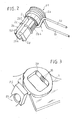
- la figure 2 est une vue en perspective de l'axe ou pivot recevant le ressort de sélection ;
- la figure 3 est une vue partielle en perspective de la partie support conformée pour recevoir le pivot du ressort de sélection, selon les caractéristiques de l' invention ;
- la figure 4 est une vue partielle en perspective montrant le pré-montage du pivot pour son réglage automatique en translation et auto-alignement avec les autres points de référence du mécanisme, sous l'effet de la mise en place de l'outil de méthode ;
- la figure 5 est une vue correspondant à la figure 4 montrant le blocage en position du pivot ;
- la figure 6 est une vue en coupe considérée selon la ligne 6-6 de la figure 4 ;
- la figure 7 est une vue en coupe considérée selon la ligne 7-7 de la figure 5.
- Figure 1 is a perspective view, schematic, of an embodiment of the housing whose gearbox control lever is equipped to block the selection of the method tool;
- Figure 2 is a perspective view of the axis or pivot receiving the selection spring;
- Figure 3 is a partial perspective view of the support portion shaped to receive the pivot of the selection spring, according to the features of the invention;
- FIG. 4 is a partial perspective view showing the pre-assembly of the pivot for its automatic adjustment in translation and self-alignment with the other reference points of the mechanism, under the effect of the implementation of the method tool ;
- Figure 5 is a view corresponding to Figure 4 showing the locking position of the pivot;
- Figure 6 is a sectional view taken along the line 6-6 of Figure 4;
- Figure 7 is a sectional view taken along the line 7-7 of Figure 5.
La figure 1 montre un exemple de boítier (B) de boíte de vitesses recevant, avec capacité d'articulation, un levier de commande (L) pour le passage et la sélection des vitesses au moyen de câbles (C1) et (C2). D'une manière connue, la sélection des vitesses, en agissant sur le levier (L), peut être effectuée soit par l'intermédiaire d'un élément de renvoi et de sélection accouplé au levier et au câble (C2), soit, comme c'est le cas selon les exemples des figures des dessins, par un doigt de sélection (D) solidaire, par exemple, de la rotule d'articulation (R) du levier par rapport au boítier (B).Figure 1 shows an example of housing (B) gearbox receiving, with articulation capacity, a control lever (L) for the passage and selection of speeds by means of cables (C1) and (C2). On the one known manner, the selection of the speeds, by acting on the lever (L), can be carried out either through a referral and selection element coupled to the lever and the cable (C2), which, as is the case examples of the figures of the drawings, by a selection finger (D) integral, for example, the ball joint (R) of the lever relative to the housing (B).
Le rappel en position du levier, pour la sélection des vitesses, s'effectue au moyen d'un ressort (1). On rappelle qu'après réglage de la boíte de la vitesses par rapport au point mort (au niveau de la commande et de la boíte de vitesses), le ressort de rappel (1) coopère avec les deux points fixes (P1) et (P2) et un point mobile (P3) correspondant au déplacement angulaire du pied de levier (L) lors de sa manoeuvre.Lever back in position, for speed selection, is effected by means of a spring (1). It is recalled that after setting the gearbox in relation to the neutral position (at the control and of the gearbox), the return spring (1) cooperates with the two points fixed (P1) and (P2) and a moving point (P3) corresponding to the displacement angle of the lever foot (L) during its maneuver.
Selon l'invention, le ressort de rappel (1) est assujetti à au moins un élément (2) monté avec capacité de déplacement en translation guidée sous l'effet d'un effort exercé sur une partie dudit ressort, notamment lors de la mise en place de l'outil de méthode (0) (figure 1). La capacité de déplacement en translation permet un auto-alignement de l'élément(2) avec les points fixes (P1) - (P2), et le point mobile (P3), afin de ne pas contraindre le ressort (1). En outre, comme il sera indiqué dans la suite de la description, l'élément (2) et la partie le recevant, présentent des agencements complémentaires aptes à assurer son blocage en translation après auto-alignement.According to the invention, the return spring (1) is subjected to at least one element (2) mounted with displacement capacity in guided translation under the effect of a force exerted on a part of that jurisdiction, in particular during the implementation of the method tool (0) (Figure 1). The ability to displacement in translation allows a self-alignment of the element (2) with the fixed points (P1) - (P2), and the moving point (P3), so as not to force the spring (1). In addition, as will be indicated later in the description, item (2) and the party receiving it, present complementary arrangements capable of ensuring its locking in translation after self-alignment.
Dans l'exemple illustré, l'élément (qui constitue le point fixe (P1))
est constitué par un axe ou pivot (2) qui présente une tête (2a) pour le
montage du ressort de rappel (1) qui est enroulé autour de ladite tête (2a)
permettant le croisement et le débordement de deux branches rectilignes et
parallèles (1a) et (1b). La tête (2a) est prolongée par une portée de centrage
(2b) apte à être engagée dans une lumière débouchante (3a) formée dans
l'épaisseur, soit d'un élément de renvoi et de sélection, soit d'une partie (3)
du boítier (B).
Cette portée de centrage (2b) présente deux zones distinctes (2b1) et
(2b2). L'ensemble de la portée de centrage (2b) est fendue selon ses
génératrices en (2b3) pour être déformable par élasticité. La zone
d'extrémité (2b1) est conformée pour être engagée librement dans la
lumière (3a) de la partie (3) avec capacité de coulissement guidé. L'autre
zone (2b2) présente des agencements de blocage (2b4) aptes à coopérer
avec des agencements complémentaires (3b) que présentent les parties
rectilignes parallèles et opposées de la lumière (3a). Les deux zones (2b1) et
(2b2) sont séparées par un profil de clipage (2c). De même, l'extrémité libre
de la zone (2b1) est terminée par un profil de clipage (2d).In the illustrated example, the element (which constitutes the fixed point (P1)) is constituted by an axis or pivot (2) which has a head (2a) for mounting the return spring (1) which is wound around said head (2a) allowing the crossing and overflow of two rectilinear and parallel branches (1a) and (1b). The head (2a) is extended by a centering surface (2b) adapted to be engaged in a through opening (3a) formed in the thickness, either of a return and selection element, or of a part (3). ) of the housing (B).
This centering span (2b) has two distinct zones (2b1) and (2b2). The entire centering bearing (2b) is split along its generatrices (2b3) to be deformable by elasticity. The end zone (2b1) is shaped to be freely engaged in the light (3a) of the portion (3) with guided sliding capacity. The other zone (2b2) has blocking arrangements (2b4) capable of cooperating with complementary arrangements (3b) that have the parallel and opposite rectilinear parts of the light (3a). The two zones (2b1) and (2b2) are separated by a clipping profile (2c). Similarly, the free end of the zone (2b1) is terminated by a clipping profile (2d).
Les deux zones (2b1) et (2b2) sont disposées l'une au-dessus de l'autre pour permettre, dans un premier temps, sous un enfoncement partiel du pivot (2), le positionnement de la zone d'extrémité (2b1), par clipage, dans la lumière (3a), en butée contre le profil de clipage (2c). Dans cette position d'engagement de la zone d'extrémité (2b1), le pivot l'axe (2) peut être déplacé en translation (figure 4). Dans un deuxième temps, après enfoncement de la totalité du pivot (2), la partie (2b2) de la portée (2b), se trouve dans la lumière (3a), en position d'imbrication des dentures complémentaires (2b4) (3b). Cette position correspond à un blocage en translation de l'axe (2) (figure 5).The two zones (2b1) and (2b2) are arranged one above the other to allow, at first, under a partial depression of the pivot (2), the positioning of the end zone (2b1), by clipping, in the light (3a), abutting against the clipping profile (2c). In this engagement position of the end zone (2b1), the pivot axis (2) can be moved in translation (Figure 4). In a second step, after depression of the entire pivot (2), the portion (2b2) of the span (2b) is located in the light (3a), in the nesting position of the teeth complementary (2b4) (3b). This position corresponds to a blockage in translation of the axis (2) (Figure 5).
Compte tenu des caractéristiques à la base de l'invention, on obtient, lors du blocage de la sélection pour le réglage du point mort, un auto-alignement des trois points (P1), (P2) et (P3). Dans l'exemple illustré, le point (P1) est constitué par le pivot (2), le point fixe (P2) par une butée (4), solidaire par exemple d'une partie du boítier, et le point mobile (P3) par l'extrémité du levier d'articulation (L), ou le doigt de sélection (D).Given the basic characteristics of the invention, we obtain, when locking the selection for the neutral setting, a self-alignment three points (P1), (P2) and (P3). In the example shown, the point (P1) is constituted by the pivot (2), the fixed point (P2) by a stop (4), solidaire for example of a portion of the housing, and the movable point (P3) by the end of the hinge lever (L), or the selection finger (D).
Le pivot (2) est engagé dans la lumière (3a) par l'extrémité (2b1). Les deux branches (1a) et (1b) du ressort de rappel (1) sont disposées en appui, de part et d'autre de l'élément de butée fixe (4), et du doigt de sélection (D). La mise en place de l'outil de méthode (O) sur le levier (L) en vue de bloquer temporairement la sélection, peut créer une contrainte au niveau notamment de l'une des branches (1a) ou (1b) du ressort (1) provoquant, d'une manière concomitante, le déplacement en translation limitée du pivot (2) et, par conséquent, l'auto-alignement des points (P1), (P2) et (P3) (figures 4 et 6). Il suffit ensuite d'enfoncer complètement le pivot (2) de manière à mettre en prise, en position d'engrènement, les dentures (2b4) de la portée (2b2) et (3b) de la lumière (3a) assurant ainsi le blocage en translation du pivot (2). On peut ensuite régler en longueur, d'une manière parfaitement connue, le câble de sélection (C2)The pivot (2) is engaged in the light (3a) by the end (2b1). The two branches (1a) and (1b) of the return spring (1) are arranged in support, on both sides of the fixed stop element (4), and the finger of selection (D). The implementation of the method tool (O) on the lever (L) to temporarily block the selection, may create a constraint to the level including one of the branches (1a) or (1b) of the spring (1) causing, concomitantly, displacement in translation limited pivot (2) and, therefore, the self-alignment of the points (P1), (P2) and (P3) (Figures 4 and 6). Then simply push in completely pivot (2) so as to engage, in meshing position, the teeth (2b4) of the span (2b2) and (3b) of the light (3a) thus ensuring locking in translation of the pivot (2). We can then adjust in length, in a perfectly known manner, the selection cable (C2)
Bien évidemment, sans pour cela sortir du cadre de l'invention, les mêmes résultats sont obtenus lorsque l'élément de butée (4) est monté avec capacité de mobilité en translation et de blocage en position, dans les conditions indiquées précédemment. Dans ce cas, l'axe ou pivot (2), où est enroulé le ressort, est fixe.Of course, without departing from the scope of the invention, the same results are obtained when the stop element (4) is mounted with mobility in translation and locking in position, in the conditions indicated previously. In this case, the axis or pivot (2), where is wound the spring, is fixed.
Les avantages ressortent bien de la description.The advantages are apparent from the description.
Claims (10)
caractérisé en ce que le ressort de rappel (1) est assujetti à un élément (2) monté dans une partie support (3) avec capacité de déplacement en translation guidé sous l'effet d'un effort exercé sur une partie du ressort de rappel (1), pour permettre un auto-alignement de l'élément (2) avec un point fixe (P2) et un point mobile (P3) correspondant au déplacement du levier afin de ne pas pré-contraindre le ressort (1) pour obtenir une synchronisation entre un outil, apte à supprimer temporairement la fonction de sélection dudit levier, et ledit ressort, ledit élément (2) et ladite partie (3) présentant des agencements complémentaires aptes à assurer le blocage en translation de l'élément (2) après son auto-alignement.Device for mounting a return spring (1) of a selector member coupled to a control lever of a gearbox for motor vehicles,
characterized in that the return spring (1) is secured to a member (2) mounted in a support portion (3) with displacement capability in guided translation under the effect of a force exerted on a portion of the return spring (1), to allow a self-alignment of the element (2) with a fixed point (P2) and a movable point (P3) corresponding to the movement of the lever so as not to pre-constrain the spring (1) to obtain a synchronization between a tool, able to temporarily remove the selection function of said lever, and said spring, said element (2) and said portion (3) having complementary arrangements able to ensure the translational locking of the element (2) after his self-alignment.
Priority Applications (1)
| Application Number | Priority Date | Filing Date | Title |
|---|---|---|---|
| SI200330853T SI1426227T1 (en) | 2002-12-03 | 2003-11-14 | Mounting device for a return spring for a vehicle gearshift lever |
Applications Claiming Priority (2)
| Application Number | Priority Date | Filing Date | Title |
|---|---|---|---|
| FR0215397A FR2847877B1 (en) | 2002-12-03 | 2002-12-03 | DEVICE FOR MOUNTING A RETRIEVAL SPRING OF A SELECTION BODY FITTED TO A LEVER FOR CONTROLLING A GEARBOX FOR MOTOR VEHICLES |
| FR0215397 | 2002-12-03 |
Publications (3)
| Publication Number | Publication Date |
|---|---|
| EP1426227A2 true EP1426227A2 (en) | 2004-06-09 |
| EP1426227A3 EP1426227A3 (en) | 2006-05-31 |
| EP1426227B1 EP1426227B1 (en) | 2007-03-28 |
Family
ID=32310020
Family Applications (1)
| Application Number | Title | Priority Date | Filing Date |
|---|---|---|---|
| EP03356176A Expired - Lifetime EP1426227B1 (en) | 2002-12-03 | 2003-11-14 | Mounting device for a return spring for a vehicle gearshift lever |
Country Status (6)
| Country | Link |
|---|---|
| EP (1) | EP1426227B1 (en) |
| AT (1) | ATE358034T1 (en) |
| DE (1) | DE60312800T2 (en) |
| ES (1) | ES2285072T3 (en) |
| FR (1) | FR2847877B1 (en) |
| SI (1) | SI1426227T1 (en) |
Cited By (1)
| Publication number | Priority date | Publication date | Assignee | Title |
|---|---|---|---|---|
| FR2927573A1 (en) * | 2008-02-19 | 2009-08-21 | Renault Sas | External control box for mechanical gearbox of motor vehicle, has support element provided with lateral tab, and opening formed on box to authorize adjustment of position of element with respect to dead center setting position of lever |
Families Citing this family (2)
| Publication number | Priority date | Publication date | Assignee | Title |
|---|---|---|---|---|
| FR2893549B1 (en) * | 2005-11-24 | 2008-02-15 | Dura Automotive Systems Soc Pa | SUPPORT ASSEMBLY FOR LEVER FOR CONTROLLING A MECHANICAL GEARBOX OF MOTOR VEHICLES |
| FR2922982B1 (en) | 2007-10-31 | 2009-11-13 | Dura Automotive Systems Sas | DEVICE FOR SYNCHRONIZING, AT THE NEUTRAL, A LEVER FOR CONTROLLING A GEARBOX WITH THE INTERNAL CONTROL OF SAID GEARBOX OF A MOTOR VEHICLE. |
Citations (2)
| Publication number | Priority date | Publication date | Assignee | Title |
|---|---|---|---|---|
| US4458549A (en) * | 1981-08-12 | 1984-07-10 | Toyota Jidosha Kogyo Kabushiki Kaisha | Select return mechanism for a transmission |
| JPS60134922A (en) * | 1983-12-24 | 1985-07-18 | Toyota Motor Corp | Select return device of speed change operating mechanism |
-
2002
- 2002-12-03 FR FR0215397A patent/FR2847877B1/en not_active Expired - Lifetime
-
2003
- 2003-11-14 ES ES03356176T patent/ES2285072T3/en not_active Expired - Lifetime
- 2003-11-14 EP EP03356176A patent/EP1426227B1/en not_active Expired - Lifetime
- 2003-11-14 AT AT03356176T patent/ATE358034T1/en not_active IP Right Cessation
- 2003-11-14 SI SI200330853T patent/SI1426227T1/en unknown
- 2003-11-14 DE DE60312800T patent/DE60312800T2/en not_active Expired - Lifetime
Patent Citations (2)
| Publication number | Priority date | Publication date | Assignee | Title |
|---|---|---|---|---|
| US4458549A (en) * | 1981-08-12 | 1984-07-10 | Toyota Jidosha Kogyo Kabushiki Kaisha | Select return mechanism for a transmission |
| JPS60134922A (en) * | 1983-12-24 | 1985-07-18 | Toyota Motor Corp | Select return device of speed change operating mechanism |
Non-Patent Citations (1)
| Title |
|---|
| PATENT ABSTRACTS OF JAPAN vol. 009, no. 299 (P-408), 27 novembre 1985 (1985-11-27) & JP 60 134922 A (TOYOTA JIDOSHA KK), 18 juillet 1985 (1985-07-18) * |
Cited By (1)
| Publication number | Priority date | Publication date | Assignee | Title |
|---|---|---|---|---|
| FR2927573A1 (en) * | 2008-02-19 | 2009-08-21 | Renault Sas | External control box for mechanical gearbox of motor vehicle, has support element provided with lateral tab, and opening formed on box to authorize adjustment of position of element with respect to dead center setting position of lever |
Also Published As
| Publication number | Publication date |
|---|---|
| SI1426227T1 (en) | 2007-12-31 |
| FR2847877B1 (en) | 2005-02-11 |
| FR2847877A1 (en) | 2004-06-04 |
| DE60312800T2 (en) | 2007-12-06 |
| EP1426227B1 (en) | 2007-03-28 |
| DE60312800D1 (en) | 2007-05-10 |
| ES2285072T3 (en) | 2007-11-16 |
| EP1426227A3 (en) | 2006-05-31 |
| ATE358034T1 (en) | 2007-04-15 |
Similar Documents
| Publication | Publication Date | Title |
|---|---|---|
| EP0805078B1 (en) | Motorised locking device for a vehicle having improved bolt movement limiting means | |
| EP2024219B1 (en) | System for locking a first shaft with respect to a second shaft eliminating clearances between said shafts | |
| FR2673448A1 (en) | CONNECTOR FOR CABLE IN A DEVICE FORMING DIRECTION LATCH. | |
| FR2922614A1 (en) | Self-blocking preadjusting and fixation device for external control cable terminal in e.g. manual mechanical gearbox of motor vehicle, has pins co-operated with lower grooves and upper grooves that maintain clamp in bottom/blocking position | |
| EP1426227B1 (en) | Mounting device for a return spring for a vehicle gearshift lever | |
| EP1790878B1 (en) | Support assembly for gear shift lever of a manual gear shift transmission for motor vehicles | |
| EP1574422A1 (en) | Cross beam of a vehicle and vehicle provided therewith | |
| FR2538754A1 (en) | Transfer press with tool change mechanism | |
| FR2775226A1 (en) | Adjuster for movement of gear selector between neutral and track for first and second gear, | |
| EP0859158A1 (en) | Device for connecting a remote control cable end fitting to a ball joint and its application in a gearbox actuator | |
| EP0597764A1 (en) | Window raiser for motor vehicle | |
| FR3123880A1 (en) | Guide bearing of a rack of a steering system | |
| EP0628455A1 (en) | Steering lock for motor vehicle | |
| EP1757829B1 (en) | Device for creating a predefined tension in an actuator using a sheathed cable | |
| EP1300535B1 (en) | Adjustable stop for movable members of a vehicle body | |
| EP1293371B1 (en) | Connecton assembly and corresponding motor vehicle | |
| EP0192531A1 (en) | Bearing for a rack-and-pinion steering | |
| WO2024023255A1 (en) | Shut-off device | |
| FR2649027A1 (en) | TOOL HOLDER FOR A MACHINE TOOL ASSOCIATED WITH AN AUTOMATIC CONNECTION DEVICE | |
| FR2594761A1 (en) | Adjustable fastening device, especially for motor vehicle headlight | |
| EP0511088A2 (en) | Automatic length adjusting device of a Bowden cable | |
| EP0524105B1 (en) | Adjusting mechanism, fixedly mounted to a body, in particular for adjusting the orientation of vehicle headlights | |
| FR2764350A1 (en) | Fastener for assembly of bumper units to chassis or bodywork of motor vehicles | |
| FR2827650A1 (en) | Mounting for attaching sleeve of Bowden cable to support has hook fitting through aperture in support and box which slides forward so that its lower side fits into aperture below hook and wedges it | |
| FR2835902A1 (en) | Automobile flexible brake tubing fixing device comprises sleeve formed by two half shells connected by articulation and coupling reliefs, half shells having radial tabs connected to insertion ramps and support surfaces |
Legal Events
| Date | Code | Title | Description |
|---|---|---|---|
| PUAI | Public reference made under article 153(3) epc to a published international application that has entered the european phase |
Free format text: ORIGINAL CODE: 0009012 |
|
| AK | Designated contracting states |
Kind code of ref document: A2 Designated state(s): AT BE BG CH CY CZ DE DK EE ES FI FR GB GR HU IE IT LI LU MC NL PT RO SE SI SK TR |
|
| AX | Request for extension of the european patent |
Extension state: AL LT LV MK |
|
| PUAL | Search report despatched |
Free format text: ORIGINAL CODE: 0009013 |
|
| AK | Designated contracting states |
Kind code of ref document: A3 Designated state(s): AT BE BG CH CY CZ DE DK EE ES FI FR GB GR HU IE IT LI LU MC NL PT RO SE SI SK TR |
|
| AX | Request for extension of the european patent |
Extension state: AL LT LV MK |
|
| 17P | Request for examination filed |
Effective date: 20060616 |
|
| GRAP | Despatch of communication of intention to grant a patent |
Free format text: ORIGINAL CODE: EPIDOSNIGR1 |
|
| AKX | Designation fees paid |
Designated state(s): AT BE BG CH CY CZ DE DK EE ES FI FR GB GR HU IE IT LI LU MC NL PT RO SE SI SK TR |
|
| GRAS | Grant fee paid |
Free format text: ORIGINAL CODE: EPIDOSNIGR3 |
|
| GRAA | (expected) grant |
Free format text: ORIGINAL CODE: 0009210 |
|
| AK | Designated contracting states |
Kind code of ref document: B1 Designated state(s): AT BE BG CH CY CZ DE DK EE ES FI FR GB GR HU IE IT LI LU MC NL PT RO SE SI SK TR |
|
| PG25 | Lapsed in a contracting state [announced via postgrant information from national office to epo] |
Ref country code: NL Free format text: LAPSE BECAUSE OF FAILURE TO SUBMIT A TRANSLATION OF THE DESCRIPTION OR TO PAY THE FEE WITHIN THE PRESCRIBED TIME-LIMIT Effective date: 20070328 Ref country code: FI Free format text: LAPSE BECAUSE OF FAILURE TO SUBMIT A TRANSLATION OF THE DESCRIPTION OR TO PAY THE FEE WITHIN THE PRESCRIBED TIME-LIMIT Effective date: 20070328 Ref country code: AT Free format text: LAPSE BECAUSE OF FAILURE TO SUBMIT A TRANSLATION OF THE DESCRIPTION OR TO PAY THE FEE WITHIN THE PRESCRIBED TIME-LIMIT Effective date: 20070328 |
|
| REG | Reference to a national code |
Ref country code: GB Ref legal event code: FG4D Free format text: NOT ENGLISH |
|
| REG | Reference to a national code |
Ref country code: CH Ref legal event code: EP |
|
| REF | Corresponds to: |
Ref document number: 60312800 Country of ref document: DE Date of ref document: 20070510 Kind code of ref document: P |
|
| REG | Reference to a national code |
Ref country code: IE Ref legal event code: FG4D Free format text: LANGUAGE OF EP DOCUMENT: FRENCH |
|
| REG | Reference to a national code |
Ref country code: RO Ref legal event code: EPE |
|
| PG25 | Lapsed in a contracting state [announced via postgrant information from national office to epo] |
Ref country code: SE Free format text: LAPSE BECAUSE OF FAILURE TO SUBMIT A TRANSLATION OF THE DESCRIPTION OR TO PAY THE FEE WITHIN THE PRESCRIBED TIME-LIMIT Effective date: 20070628 |
|
| GBT | Gb: translation of ep patent filed (gb section 77(6)(a)/1977) |
Effective date: 20070704 |
|
| PG25 | Lapsed in a contracting state [announced via postgrant information from national office to epo] |
Ref country code: PT Free format text: LAPSE BECAUSE OF FAILURE TO SUBMIT A TRANSLATION OF THE DESCRIPTION OR TO PAY THE FEE WITHIN THE PRESCRIBED TIME-LIMIT Effective date: 20070828 |
|
| NLV1 | Nl: lapsed or annulled due to failure to fulfill the requirements of art. 29p and 29m of the patents act | ||
| REG | Reference to a national code |
Ref country code: ES Ref legal event code: FG2A Ref document number: 2285072 Country of ref document: ES Kind code of ref document: T3 |
|
| REG | Reference to a national code |
Ref country code: IE Ref legal event code: FD4D |
|
| PG25 | Lapsed in a contracting state [announced via postgrant information from national office to epo] |
Ref country code: IE Free format text: LAPSE BECAUSE OF FAILURE TO SUBMIT A TRANSLATION OF THE DESCRIPTION OR TO PAY THE FEE WITHIN THE PRESCRIBED TIME-LIMIT Effective date: 20070328 Ref country code: DK Free format text: LAPSE BECAUSE OF FAILURE TO SUBMIT A TRANSLATION OF THE DESCRIPTION OR TO PAY THE FEE WITHIN THE PRESCRIBED TIME-LIMIT Effective date: 20070328 |
|
| PLBE | No opposition filed within time limit |
Free format text: ORIGINAL CODE: 0009261 |
|
| STAA | Information on the status of an ep patent application or granted ep patent |
Free format text: STATUS: NO OPPOSITION FILED WITHIN TIME LIMIT |
|
| 26N | No opposition filed |
Effective date: 20080102 |
|
| PG25 | Lapsed in a contracting state [announced via postgrant information from national office to epo] |
Ref country code: GR Free format text: LAPSE BECAUSE OF FAILURE TO SUBMIT A TRANSLATION OF THE DESCRIPTION OR TO PAY THE FEE WITHIN THE PRESCRIBED TIME-LIMIT Effective date: 20070629 |
|
| BERE | Be: lapsed |
Owner name: DURA AUTOMOTIVE SYSTEMS Effective date: 20071130 |
|
| PG25 | Lapsed in a contracting state [announced via postgrant information from national office to epo] |
Ref country code: MC Free format text: LAPSE BECAUSE OF NON-PAYMENT OF DUE FEES Effective date: 20071130 |
|
| PG25 | Lapsed in a contracting state [announced via postgrant information from national office to epo] |
Ref country code: CH Free format text: LAPSE BECAUSE OF NON-PAYMENT OF DUE FEES Effective date: 20071130 Ref country code: LI Free format text: LAPSE BECAUSE OF NON-PAYMENT OF DUE FEES Effective date: 20071130 |
|
| REG | Reference to a national code |
Ref country code: CH Ref legal event code: PL |
|
| PG25 | Lapsed in a contracting state [announced via postgrant information from national office to epo] |
Ref country code: BE Free format text: LAPSE BECAUSE OF NON-PAYMENT OF DUE FEES Effective date: 20071130 |
|
| REG | Reference to a national code |
Ref country code: FR Ref legal event code: ST Effective date: 20080930 |
|
| PG25 | Lapsed in a contracting state [announced via postgrant information from national office to epo] |
Ref country code: EE Free format text: LAPSE BECAUSE OF FAILURE TO SUBMIT A TRANSLATION OF THE DESCRIPTION OR TO PAY THE FEE WITHIN THE PRESCRIBED TIME-LIMIT Effective date: 20070328 |
|
| PG25 | Lapsed in a contracting state [announced via postgrant information from national office to epo] |
Ref country code: FR Free format text: LAPSE BECAUSE OF NON-PAYMENT OF DUE FEES Effective date: 20071130 |
|
| PG25 | Lapsed in a contracting state [announced via postgrant information from national office to epo] |
Ref country code: CY Free format text: LAPSE BECAUSE OF FAILURE TO SUBMIT A TRANSLATION OF THE DESCRIPTION OR TO PAY THE FEE WITHIN THE PRESCRIBED TIME-LIMIT Effective date: 20070328 |
|
| PG25 | Lapsed in a contracting state [announced via postgrant information from national office to epo] |
Ref country code: LU Free format text: LAPSE BECAUSE OF NON-PAYMENT OF DUE FEES Effective date: 20071114 Ref country code: BG Free format text: LAPSE BECAUSE OF FAILURE TO SUBMIT A TRANSLATION OF THE DESCRIPTION OR TO PAY THE FEE WITHIN THE PRESCRIBED TIME-LIMIT Effective date: 20070628 |
|
| PG25 | Lapsed in a contracting state [announced via postgrant information from national office to epo] |
Ref country code: TR Free format text: LAPSE BECAUSE OF FAILURE TO SUBMIT A TRANSLATION OF THE DESCRIPTION OR TO PAY THE FEE WITHIN THE PRESCRIBED TIME-LIMIT Effective date: 20070328 Ref country code: HU Free format text: LAPSE BECAUSE OF FAILURE TO SUBMIT A TRANSLATION OF THE DESCRIPTION OR TO PAY THE FEE WITHIN THE PRESCRIBED TIME-LIMIT Effective date: 20070929 |
|
| PGFP | Annual fee paid to national office [announced via postgrant information from national office to epo] |
Ref country code: IT Payment date: 20151124 Year of fee payment: 13 |
|
| PGFP | Annual fee paid to national office [announced via postgrant information from national office to epo] |
Ref country code: CZ Payment date: 20151023 Year of fee payment: 13 Ref country code: SI Payment date: 20151021 Year of fee payment: 13 Ref country code: ES Payment date: 20151126 Year of fee payment: 13 Ref country code: SK Payment date: 20151021 Year of fee payment: 13 Ref country code: RO Payment date: 20151022 Year of fee payment: 13 |
|
| PG25 | Lapsed in a contracting state [announced via postgrant information from national office to epo] |
Ref country code: SK Free format text: LAPSE BECAUSE OF NON-PAYMENT OF DUE FEES Effective date: 20161114 Ref country code: RO Free format text: LAPSE BECAUSE OF NON-PAYMENT OF DUE FEES Effective date: 20161114 Ref country code: CZ Free format text: LAPSE BECAUSE OF NON-PAYMENT OF DUE FEES Effective date: 20161114 |
|
| REG | Reference to a national code |
Ref country code: SK Ref legal event code: MM4A Ref document number: E 2106 Country of ref document: SK Effective date: 20161114 |
|
| PG25 | Lapsed in a contracting state [announced via postgrant information from national office to epo] |
Ref country code: SI Free format text: LAPSE BECAUSE OF NON-PAYMENT OF DUE FEES Effective date: 20161115 |
|
| REG | Reference to a national code |
Ref country code: SI Ref legal event code: KO00 Effective date: 20170804 |
|
| PG25 | Lapsed in a contracting state [announced via postgrant information from national office to epo] |
Ref country code: IT Free format text: LAPSE BECAUSE OF NON-PAYMENT OF DUE FEES Effective date: 20161114 |
|
| PG25 | Lapsed in a contracting state [announced via postgrant information from national office to epo] |
Ref country code: ES Free format text: LAPSE BECAUSE OF NON-PAYMENT OF DUE FEES Effective date: 20161115 |
|
| REG | Reference to a national code |
Ref country code: ES Ref legal event code: FD2A Effective date: 20180628 |
|
| PGFP | Annual fee paid to national office [announced via postgrant information from national office to epo] |
Ref country code: GB Payment date: 20221128 Year of fee payment: 20 Ref country code: DE Payment date: 20221125 Year of fee payment: 20 |
|
| REG | Reference to a national code |
Ref country code: DE Ref legal event code: R071 Ref document number: 60312800 Country of ref document: DE |
|
| REG | Reference to a national code |
Ref country code: GB Ref legal event code: PE20 Expiry date: 20231113 |
|
| PG25 | Lapsed in a contracting state [announced via postgrant information from national office to epo] |
Ref country code: GB Free format text: LAPSE BECAUSE OF EXPIRATION OF PROTECTION Effective date: 20231113 |
|
| PG25 | Lapsed in a contracting state [announced via postgrant information from national office to epo] |
Ref country code: GB Free format text: LAPSE BECAUSE OF EXPIRATION OF PROTECTION Effective date: 20231113 |