EP1426102A2 - Process for decreasing content of particulate material contained in exhaust gas from lean burn engine or the like - Google Patents
Process for decreasing content of particulate material contained in exhaust gas from lean burn engine or the like Download PDFInfo
- Publication number
- EP1426102A2 EP1426102A2 EP03026810A EP03026810A EP1426102A2 EP 1426102 A2 EP1426102 A2 EP 1426102A2 EP 03026810 A EP03026810 A EP 03026810A EP 03026810 A EP03026810 A EP 03026810A EP 1426102 A2 EP1426102 A2 EP 1426102A2
- Authority
- EP
- European Patent Office
- Prior art keywords
- particulate material
- exhaust gas
- plasma
- lean burn
- content
- Prior art date
- Legal status (The legal status is an assumption and is not a legal conclusion. Google has not performed a legal analysis and makes no representation as to the accuracy of the status listed.)
- Granted
Links
Images





Classifications
-
- B—PERFORMING OPERATIONS; TRANSPORTING
- B01—PHYSICAL OR CHEMICAL PROCESSES OR APPARATUS IN GENERAL
- B01D—SEPARATION
- B01D53/00—Separation of gases or vapours; Recovering vapours of volatile solvents from gases; Chemical or biological purification of waste gases, e.g. engine exhaust gases, smoke, fumes, flue gases, aerosols
- B01D53/34—Chemical or biological purification of waste gases
- B01D53/92—Chemical or biological purification of waste gases of engine exhaust gases
-
- B—PERFORMING OPERATIONS; TRANSPORTING
- B01—PHYSICAL OR CHEMICAL PROCESSES OR APPARATUS IN GENERAL
- B01D—SEPARATION
- B01D53/00—Separation of gases or vapours; Recovering vapours of volatile solvents from gases; Chemical or biological purification of waste gases, e.g. engine exhaust gases, smoke, fumes, flue gases, aerosols
- B01D53/32—Separation of gases or vapours; Recovering vapours of volatile solvents from gases; Chemical or biological purification of waste gases, e.g. engine exhaust gases, smoke, fumes, flue gases, aerosols by electrical effects other than those provided for in group B01D61/00
-
- F—MECHANICAL ENGINEERING; LIGHTING; HEATING; WEAPONS; BLASTING
- F01—MACHINES OR ENGINES IN GENERAL; ENGINE PLANTS IN GENERAL; STEAM ENGINES
- F01N—GAS-FLOW SILENCERS OR EXHAUST APPARATUS FOR MACHINES OR ENGINES IN GENERAL; GAS-FLOW SILENCERS OR EXHAUST APPARATUS FOR INTERNAL-COMBUSTION ENGINES
- F01N3/00—Exhaust or silencing apparatus having means for purifying, rendering innocuous, or otherwise treating exhaust
- F01N3/08—Exhaust or silencing apparatus having means for purifying, rendering innocuous, or otherwise treating exhaust for rendering innocuous
- F01N3/0892—Electric or magnetic treatment, e.g. dissociation of noxious components
Definitions
- the present invention relates to a process for decreasing the content of a particulate material contained in an exhaust gas from a lean burn engine or the like.
- this type of the particulate material has a double-layer structure comprising a carbon solid fraction (soot) and a soluble organic fraction (SOF) covering the carbon solid fraction.
- the conventionally known process has the following problems: an exhausting resistance is increased by the ceramic filter, and hence an engine output cannot be sufficiently utilized; the engine control for raising the temperature of the exhaust gas is complicated; and the filter temperature may exceed 1,000°C in some cases during burning of the particulate material, resulting in damage to the ceramic filter.
- a process for decreasing the content of a particulate material contained in an exhaust gas from a lean burn engine comprising the steps of: generating plasma in the exhaust gas discharged from the lean burn engine and containing the particulate material, to thereby produce a plurality of O ( 1 D) radicals and subsequently produce a plurality of per-hydroxide excited species; and oxidizing the particulate material by the per-hydroxide excited species.
- O( 1 D) radicals and ozone excited species are produced by the collision between electrons released from electrodes and oxygen molecules
- ⁇ hydroxide excited species are produced by the reaction of O( 1 D) radicals and ozone excited species with water
- ⁇ per-hydroxide excited species HOO* having a strong oxidizing force are produced by the reaction of the hydroxide excited species with oxygen.
- the production of the per-hydroxide excited species is carried out independent of the temperature of the exhaust gas.
- the particulate material is oxidized and converted by the per-hydroxide excited species. The conversion of the particulate material by the oxidization is conducted continuously and at a relatively low temperature.
- a plasma generating device has a good gas permeability, as compared with a filter, so that even if the plasma generating device is incorporated in an exhaust pipe, an increase in exhausting resistance is suppressed to a low level. Therefore, an influence cannot be exerted to an engine output.
- an intensity E of electric field is set at a value equal to or larger than 3.0 kV/mm and a power density Dw is set at a value equal to or larger than 1 W/cm 3 in the plasma generating conditions, the amount of released high-energy electrons existing in the plasma is increased, and hence the production of the per-hydroxide excited species is efficiently conducted, whereby the conversion of the particulate material by the oxidization can be enhanced.
- E ⁇ 3.0 kV/mm and Dw ⁇ 1 W/cm 3 is lacked, the above-described effect cannot be obtained.
- the entire surface of the dielectric is uniformly charged upon application of a voltage. Therefore, the entire space between the dielectric and the other electrode opposed to the dielectric constitutes a plasma space, so that the frequency of random contact between the particulate material and the per-hydroxide excited species can be increased to enhance the conversion of the particulate material by the oxidization.
- opposed surfaces of the opposed electrodes are covered with dielectrics, respectively, an increase in the applied voltage is provided by an increase in impedance, but it is possible to provide a converting performance equivalent to that in the case where the one surface is covered, by setting the plasma generating conditions as described above.
- a process for decreasing the content of a particulate material contained in an exhaust gas from a lean burn engine or the like and comprising a carbon solid fraction and a soluble organic fraction covering the carbon solid fraction comprising the steps of: subjecting the soluble organic fraction to the reaction with oxygen under the presence of a catalyst to oxidize the soluble organic fraction; generating plasma in the exhaust gas to produce plasma excited species; and oxidizing the carbon solid fraction by the plasma excited species.
- the soluble organic fraction usually comprises a polycyclic aromatic hydrocarbon and the like.
- a large amount of oxygen is contained in the exhaust gas from the lean burn engine. Therefore, if the catalyst is present, oxygen and the soluble organic fraction are brought into contact with each other on the catalyst, whereby the soluble organic fraction is oxidized and removed. This reaction occurs even at a low temperature.
- the plasma excited species are produced by the collision between electrons released from electrodes and gas molecules.
- the plasma excited species include large numbers of O ( 1 D) radicals, hydroxide excited species OH*, per-hydroxide excited species HOO* and the like each having a strong oxidizing force, and hence the carbon solid fraction is oxidized by the plasma excited species.
- the carbon solid fraction is liable to be electrically charged in the plasma, so that there is generated a phenomenon that the carbon solid fraction is oxidized efficiently in a state in which they have been collected electrostatically on the electrodes.
- the significance of the preliminary removal of the soluble organic fraction from the surface of the particulate material resides in this point.
- the conversion of the carbon solid fraction by the oxidization as described above is conducted continuously and moreover at a relatively low temperature.
- a plasma generating device has a good gas permeability, as compared with a filter, so that even if the plasma generating device is incorporated in an exhaust pipe, an increase in exhausting resistance is suppressed to a low level. Therefore, an influence cannot be exerted to an engine output.
- At least one selected from the group consisting of Pt, Pd, Rh, Cu, Ag and Au is used as the catalyst.
- an intensity E of electric field is set at a value equal to or larger than 3.0 kV/mm and a power density Dw is set at a value equal to or larger than 1 W/cm 3 in the plasma generating conditions, the amount of released high-energy electrons existing in the plasma is increased, and hence the production of the plasma excited species is efficiently conducted, whereby the conversion of the carbon solid fraction by the oxidization can be enhanced.
- E ⁇ 3.0 kV/mm and Dw ⁇ 1 W/cm 3 is lacked, the above-described effect cannot be obtained.
- the entire surface of the dielectric is uniformly charged upon application of a voltage. Therefore, the entire space between the dielectric and the other electrode opposed to the dielectric constitutes a plasma space, so that the frequency of random contact between the carbon solid fraction and the plasma excited species can be increased to enhance the conversion of the carbon solid fraction by the oxidization.
- opposed surfaces of the opposed electrodes are covered with dielectrics, respectively, an increase in the applied voltage is brought about with an increase in impedance, but it is possible to provide a converting performance equivalent to that in the case where the one surface is covered, by setting the plasma generating conditions as described above.
- a process for decreasing the content of a particulate material contained in an exhaust gas from a lean burn engine or the like comprising the steps of: generating plasma in the exhaust gas discharged from the lean burn engine and containing the particulate material to produce a plurality of nitrogen dioxide molecules and a plurality of ozone molecules; and oxidizing the particulate material by the nitrogen dioxide molecules and the ozone molecules.
- oxygen atom excited species are produced by the collision between released electrons and oxygen molecules
- ⁇ ozone is produced by the reaction of the oxygen atom excited species with oxygen molecules
- NO 2 nitrogen dioxide
- NO nitrogen monoxide
- the productions of the nitrogen dioxide and ozone are carried out independent of the temperature of the exhaust gas.
- the particulate material PM is oxidized and converted based on the reaction represented by PM + NO 2 + O 3 ⁇ CO 2 + H 2 O + N 2 .
- the conversion of the particulate material by the oxidization is conducted continuously and moreover at a relatively low temperature.
- a plasma generating device has a good gas permeability, as compared with a filter, so that even if the plasma generating device is incorporated in an exhaust pipe, an increase in exhausting resistance is suppressed to a low level. Therefore, an influence cannot be exerted to an engine output.
- a process for decreasing the content of a particulate material contained in an exhaust gas from a lean burn engine comprising the steps of: generating plasma in the exhaust gas discharged from the lean burn engine and containing the particulate material to produce a plurality of nitrogen dioxide molecules and a plurality of ozone molecules; oxidizing the particulate material by the nitrogen dioxide molecules and the ozone molecules; and subjecting the particulate material to the reaction with the nitrogen dioxide molecules and the ozone molecules in the presence of a catalyst to oxidize the particulate material.
- the above-described reaction namely, the reaction represented by PM + NO 2 + O 3 ⁇ CO 2 + H 2 O + N 2 can be promoted to greatly increase the decrement rate of the particulate material.
- At least one selected from the group consisting of Pt, Pd, Rh, Cu, Ag and Au is used as the catalyst.
- an intensity E of electric field is set at a value equal to or larger than 3.0 kV/mm and a power density Dw is set at a value equal to or larger than 1 W/cm 3 in the plasma generating conditions, the amount of released high-energy electrons existing in the plasma is increased, and hence the productions of the nitrogen dioxide and ozone are efficiently conducted, whereby the conversion of the carbon solid fraction by the oxidization can be enhanced.
- E ⁇ 3.0 kV/mm and Dw ⁇ 1 W/cm 3 is lacked, the above-described effect cannot be obtained.
- the entire surface of the dielectric is uniformly charged upon application of a voltage. Therefore, the entire space between the dielectric and the other electrode opposed to the dielectric constitutes a plasma space, so that the frequency of random contact of the particulate material with the nitrogen dioxide and ozone can be increased to enhance the conversion of the carbon solid fraction by the oxidization.
- opposed surfaces of the opposed electrodes are covered with dielectrics, respectively, an increase in the applied voltage is provided by an increase in impedance, but it is possible to provide a converting performance equivalent to that in the case where the one surface is covered, by setting the plasma generating conditions as described above.
- a commercially available diesel generator 2 is selected as a source of generating an exhaust gas containing a particulate material.
- a first flow rate regulating valve 4 1 is mounted in an exhaust pipe 3 of the diesel generator 2.
- a conduit 5 is connected at one end between the diesel generator 2 and the first flow rate regulating valve 4 1 .
- a second flow rate regulating valve 4 2 , a heater 6, a plasma generating device PG and a flow-meter 8 are mounted in the exhaust pipe 3 sequentially in the named order from the side of the exhaust pipe 3. The other end of the conduit 5 opens to the atmosphere.
- a first branch pipe 9 1 is connected at one end between the heater 6 and the plasma generating device PG, and at the other end to a first port p 1 of a three-way valve 10.
- a second branch pipe 9 2 is also connected at one end between the plasma generating device PG and the flow-meter 8, and at the other end to a second port p 2 of the three-way valve 10.
- Another conduit 11 is connected at one end to a third port p 3 of the three-way valve 10, and at the other end to a suction port of a suction pump 12.
- a filter 13 is mounted in the conduit 11.
- the diesel generator 2 is EXT12D made by Hyundai Motor Co., Ltd., and the specification thereof is as follows: the type of an engine: a water-cooled 3-cylinder and 4-cycle diesel engine; a total displacement: 1061 cc; a fuel used: diesel light oil; a rated output: 12 kVA.
- the filter 13 is a Teflon-coated filter made by German Laboratory, and has a mesh size of 0.3 ⁇ m mesh.
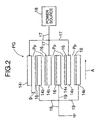
- the plasma generating device PG includes a plurality of first to sixth electrodes 14 1 to 14 6 made of a metal, each of which is formed into a plate shape in the illustrated embodiment.
- the first to sixth electrodes 14 1 to 14 6 are mounted in a housing 15 (see Fig. 1) so that they are parallel to a direction A of flowing of an exhaust gas, and the adjacent electrodes 14 1 and 14 2 ; 14 2 and 14 3 ; 14 3 and 14 4 ; 14 4 and 14 5 ; 14 5 and 14 6 are opposed to each other.
- the surface of the first electrode 14 1 located at one end, which is opposed to the second electrode 14 2 , is a non-coated metal surface, but the surface of the second electrode 14 2 , which is opposed to the first electrode 14 1 , is coated entirely with a dielectric 16.
- the arrangement relationship between the opposed surfaces of the first and second electrodes 14 1 and 14 2 applies to those between the second and third electrodes 14 2 and 14 3 ; between the third and fourth electrodes 14 3 and 14 4 ; between the fourth and fifth electrodes 14 4 and 14 5 ; and between the fifth and sixth electrodes 14 5 and 14 6 .
- the first, third and fifth electrodes 14 1 , 14 3 and 14 5 are connected to a power source 18 through lead wires 17, while the second, fourth and sixth electrodes 14 2 , 14 4 and 14 6 are earthed through lead wires 19.
- the entire surface of each of the dielectrics 16 is uniformly charged upon application of a voltage, and hence the entire space between each of the dielectrics 16 and each of the electrodes 14 1 to 14 6 which is opposed thereto constitutes a plasma space Pp.
- the plasma spaces Pp are formed between the first and second electrodes 14 1 and 14 2 ; between the second and third electrodes 14 2 and 14 3 ; between the third and fourth electrodes 14 3 and 14 4 ; between the fourth and fifth electrodes 14 4 and 14 5 ; and between the fifth and sixth electrodes 14 5 and 14 6 . That is, each of the plasma spaces Pp is defined by the opposed electrodes.
- Each of the first to sixth electrodes 14 1 to 14 6 is formed of a stainless steel (e.g., JIS SUS316), and has a size of 20 mm long, 50 mm wide and 1.0 mm thick, with a transverse side extending along the exhaust gas flowing direction A.
- Each of the dielectrics 16 comprises an alumina (Al 2 O 3 ) layer having a thickness of 0.5 mm, which is bonded to each of the second to sixth electrodes 14 2 to 14 6 by the mechanical pressing. The adhesion using an adhesive, the flame spraying or the like may be also utilized for such bonding.
- a gap g in each of the plasma spaces Pp namely, a distance between each of the adjacent electrodes 14 1 to 14 6 and each of the dielectrics 16 is 0.5 mm.
- a particulate material content reducing test was carried out using the above-described equipment 1, according to the following procedure:
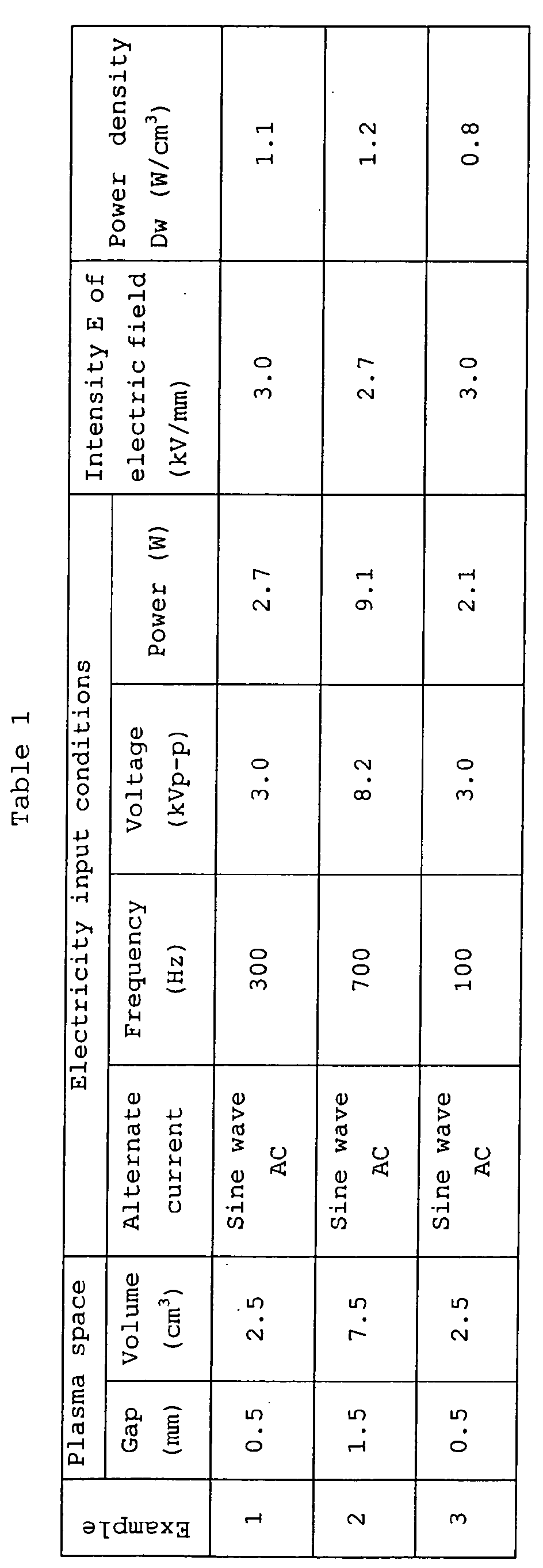
- Table 1 shows plasma generating conditions for Examples 1 to 3.
- the intensity E of electric field is a value provided by dividing a voltage [(kV p-p )/2] applied between the opposed electrodes such as between the first and second electrodes 14 1 and 14 2 by the gap g (mm)
- Table 2 shows amounts of the particulate material before and after the plasma treatment, and decrement amounts and decrement rates of the particulate material decreased by the plasma treatment for Examples 1 to 3.
- Example 1 1.3 0.2 1.1 84.6
- Example 2 1.2 0.7 0.5 41.7
- Example 3 1.4 0.8 0.6 42.9
- Fig.3 is a graph based on Table 2 and showing amounts of the particulate material before and after the plasma treatment for Examples 1 to 3.
- per-hydroxide excited species HOO* can be efficiently produced by setting the intensity E of electric field at a value equal to or larger than 3.0 kV/mm and the power density Dw at a value equal to or larger than 1 W/cm 3 , whereby the decrement rate of the particulate material can be increased to about 84.6 %.
- the intensity E of electric field is preferably in a range of 3 kV/mm ⁇ E ⁇ 15 kV/mm, and the power density Dw is preferably in a range of 1 W/cm 3 ⁇ Dw ⁇ 10 W/cm 3 .
- the decrement rate of the particulate material is lower and approximately half of that in Example 1, because one of the intensity E of electric field and the power density Dw dose not satisfies the above-described requirement.
- Embodiment I is applicable for decreasing the content of a particulate material contained in an exhaust gas discharged from an automobile, a factory or the like.
- a commercially available diesel generator 2 is selected as a source of generating an exhaust gas containing a particulate material.
- a first flow rate regulating valve 4 1 is mounted in an exhaust pipe 3 of the diesel generator 2.
- a conduit 5 is connected at one end between the diesel generator 2 and the first flow rate regulating valve 4 1 , and a second flow rate regulating valve 4 2 , a heater 6, a catalytic reactor CR, a plasma generating device PG and a flow-meter 8 are mounted on the exhaust pipe 3 sequentially in the named order from the side of the exhaust pipe 3.
- the other end of the conduit 5 opens to the atmosphere.
- a first branch pipe 9 1 is connected at one end between the heater 6 and the catalytic reactor CR, and at the other end to a suction port of a suction pump 12.
- a first on-off valve 20 1 and a filter 13 are mounted in the first branch pipe 9 1 sequentially from the side of the conduit 5.
- a second branch pipe 9 2 is also connected at one end between the catalytic reactor CR and the plasma generating device PG, and at the other end between the first on-off valve 20 1 and the filter 13 in the first branch pipe 9 1 .
- a second on-off valve 20 2 is mounted in the second branch pipe 9 2 .
- a third branch pipe 9 3 is connected at one end between the plasma generating device PG and the flow-meter 8, and at the other end between a connection of the second branch pipe 9 2 and the filter 13 in the first branch pipe 9 1 .
- a third on-off valve 20 3 is mounted in the third branch pipe 9 3 .
- the diesel generator 2 is EXT12D made by Hyundai Motor Co. Ltd., and the specification thereof is as follows: the type of an engine: a water-cooled 3-cylinder and 4-cycle diesel engine; a total displacement: 1061 cc; a fuel used: diesel light oil; a rated output: 12 kVA.
- the filter 13 is a Teflon-coated filter made by German Laboratory, and has a mesh size of 0.3 ⁇ m mesh.
- the plasma generating device PG has the same structure as that in Embodiment I and includes a plurality of first to sixth electrodes 14 1 to 14 6 made of a metal, each of which is formed into a plate shape in the illustrated embodiment.
- the first to sixth electrodes 14 1 to 14 6 are mounted in a housing 15 (see Fig.4) so that they are parallel to a direction A of flowing of an exhaust gas, and the adjacent electrodes 14 1 and 14 2 ; 14 2 and 14 3 ; 14 3 and 14 4 ; 14 4 and 14 5 ; 14 5 and 14 6 are opposed to each other.
- the surface of the first electrode 14 1 located at one end, which is opposed to the second electrode 14 2 , is a non-coated metal surface, but the surface of the second electrode 14 2 , which is opposed to the first electrode 14 1 , is coated entirely with a dielectric 16.
- the arrangement relationship between the opposed surfaces of the first and second electrodes 14 1 and 14 2 applies to those between the second and third electrodes 14 2 and 14 3 ; between the third and fourth electrodes 14 3 and 14 4 ; between the fourth and fifth electrodes 14 4 and 14 5 ; and between the fifth and sixth electrodes 14 5 and 14 6 .
- the first, third and fifth electrodes 14 1 , 14 3 and 14 5 are connected to a power source 18 through lead wires 17, while the second, fourth and sixth electrodes 14 2 , 14 4 and 14 6 are earthed through lead wires 19.
- the entire surface of each of the dielectrics 16 is uniformly charged upon application of a voltage, and hence the entire space between each of the dielectrics 16 and each of the electrodes 14 1 to 14 6 which is opposed thereto constitutes a plasma space Pp.
- the plasma spaces Pp are formed between the first and second electrodes 14 1 and 14 2 ; between the second and third electrodes 14 2 and 14 3 ; between the third and fourth electrodes 14 3 and 14 4 ; between the fourth and fifth electrodes 14 4 and 14 5 ; and between the fifth and sixth electrodes 14 5 and 14 6 . That is, each of the plasma spaces Pp is defined by the opposed electrodes.
- Each of the first to sixth electrodes 14 1 to 14 6 is formed of a stainless steel (e.g., JIS SUS316), and has a size of 20 mm long, 50 mm wide and 1.0 mm thick, with a transverse side extending along the exhaust gas flowing direction A.
- Each of the dielectrics 16 comprises an alumina (Al 2 O 3 ) layer having a thickness of 0.5 mm, which is bonded to each of the second to sixth electrodes 14 2 to 14 6 by the mechanical pressing. The adhesion using an adhesive, the flame spraying or the like may be also utilized for such bonding.
- a gap g in each of the plasma spaces Pp namely, a distance between each of the adjacent electrodes 14 1 to 14 6 and each of the dielectric 16 is 0.5 mm.
- the catalytic reactor CR comprises a honeycomb carrier and platinum (Pt) carried as a catalyst on the honeycomb carrier, and is placed in a housing 21.
- platinum platinum
- the following process was adopted: (i) 80 grams of a solution of platinum dinitrodiamine nitric acid [Pt(NH 3 ) 2 (NO 2 ) 2 ⁇ HNO 3 ] containing 5 % by weight of platinum, 96 grams of commercially available ⁇ -Al 2 O 3 , and 1,000 grams of ion-exchange water were mixed together, and at the same time, an excessive amount of water was removed; (ii) a mixture was dried at 200°C for 2 hours; (iii) a powder of Al 2 O 3 carrying platinum was produced by calcining the mixture at 600°C for 2 hours; (iv) 90 grams of the powder of Al 2 O 3 carrying platinum, 50 grams of an SiO 2 binder (containing 20 % by weight of SiO 2 ) and 150 grams of ion-exchange water were mixed together
- This type of catalytic reactor CR has a structure substantially same as that of a catalytic converter, and hence the exhausting resistance cannot be greatly increased.
- a particulate material content-decreasing test was carried out using the above-described equipment by the following procedure:
- Example 4 The process using platinum as the catalyst as described above is defined as Example 4.
- Example 5 A particulate material content-decreasing test was carried out as Example 5 in a similar manner, except that a catalytic reactor CR having silver (Ag) as a catalyst was used, and the temperature of an exhaust gas flowing into the plasma generating device PG was set at 250°C.
- a catalytic reactor CR having silver (Ag) as a catalyst was used, and the temperature of an exhaust gas flowing into the plasma generating device PG was set at 250°C.
- this process was the same as Example 3, except that a mixture comprising 4. 72 grams of silver nitrate (AgNO 3 ) 97 grams of commercially available ⁇ -Al 2 O 3 , and 1,000 grams of ion-exchange water were used as a silver-containing solution, and the amount of silver carried on the honeycomb carrier was set at 3 g/L.
- the plasma excited species include O( 1 D) radicals, hydroxide excited species OH*, per-hydroxide excited species HOO* and the like.
- Table 3 shows plasma generating conditions for Examples 4 and 5.
- the intensity E of electric field is a value provided by dividing a voltage [(kV p-p )/2] applied between the opposed electrodes such as between the first and second electrodes 14 1 and 14 2 by the gap g (mm)
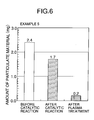
- Table 4 shows amounts of the particulate material before and after the catalytic reaction and after the plasma treatment, and decrement amounts and decrement rates of the particulate material decreased by the catalytic reaction and the plasma treatment for Examples 4 and 5.
- Figs.5 and 6 are graphs based on Table 4 and showing amounts of the particulate material before and after the catalytic reaction and after the plasma treatment for Examples 4 and 5.
- plasma excited species can be efficiently produced by setting the intensity E of electric field at a value equal to or larger than 3.0 kV/mm and setting the power density Dw at a value equal to or larger than 1 W/cm 3 , whereby the decrement rate of the particulate material can be increased up to about 92 % or more.
- the intensity E of electric field is preferably in a range of 3 kV/mm ⁇ E ⁇ 15 kV/mm, and the power density Dw is preferably in a range of 1 W/cm 3 ⁇ Dw ⁇ 10 W/cm 3 .
- Embodiment II is applicable for decreasing the content of a particulate material contained in an exhaust gas discharged from an automobile, a factory or the like.
- a commercially available diesel generator 2 is selected as a source of generating an exhaust gas containing a particulate material.
- a first flow rate regulating valve 4 1 is mounted in an exhaust pipe 3 of the diesel generator 2.
- a conduit 5 is connected at one end between the diesel generator 2 and the first flow rate regulating valve 4 1 , and a second flow rate regulating valve 4 2 , a heater 6, a plasma generating device PG, a catalytic reactor CR and a flow-meter 8 are mounted on the exhaust pipe 3 sequentially in the named order from the side of the exhaust pipe 3.
- the other end of the conduit 5 opens to the atmosphere.
- a first branch pipe 9 1 is connected at one end between the heater 6 and the plasma generating device PG, and at the other end to a suction port of a suction pump 12.
- a first on-off valve 20 1 and a filter 13 are mounted in the first branch pipe 9 1 sequentially from the side of the conduit 5.
- a second branch pipe 9 2 is also connected at one end between the plasma generating device PG and the catalytic reactor CR, and at the other end between the first on-off valve 20 1 and the filter 13 in the first branch pipe 9 1 .
- a second on-off valve 20 2 is mounted in the second branch pipe 9 2 .
- a third branch pipe 9 3 is connected at one end between the catalytic reactor CR and the flow-meter 8, and at the other end between a connection of the second branch pipe 9 2 and the filter 13 in the first branch pipe 9 1 .
- a third on-off valve 20 3 is mounted in the third branch pipe 9 3 .
- the diesel generator 2 is EXT12D made by Hyundai Motor Co. Ltd., and the specification thereof is as follows: the type of an engine: a water-cooled 3-cylinder and 4-cycle diesel engine; a total displacement: 1061 cc; a fuel used: diesel light oil; a rated output: 12 kVA.
- the filter 13 is a Teflon-coated filter made by German Laboratory, and has a mesh size of 0.3 ⁇ m mesh.
- the plasma generating device PG has the same structure as that in Embodiments I and II, and includes a plurality of first to sixth electrodes 14 1 to 14 6 made of a metal, each of which is formed into a plate shape in the illustrated embodiment.
- the first to sixth electrodes 14 1 to 14 6 are mounted in a housing 15 (see Fig.7) so that they are parallel to a direction A of flowing of an exhaust gas, and the adjacent electrodes 14 1 and 14 2 ; 14 2 and 14 3 ; 14 3 and 14 4 ; 14 4 and 14 5 ; 14 5 and 14 6 are opposed to each other.
- the surface of the first electrode 14 1 located at one end, which is opposed to the second electrode 14 2 , is a non-coated metal surface, but the surface of the second electrode 14 2 , which is opposed to the first electrode 14 1 , is coated entirely with a dielectric 16.
- the arrangement relationship between the opposed surfaces of the first and second electrodes 14 1 and 14 2 applies to those between the second and third electrodes 14 2 and 14 3 ; between the third and fourth electrodes 14 3 and 14 4 ; between the fourth and fifth electrodes 14 4 and 14 5 ; and between the fifth and sixth electrodes 14 5 and 14 6 .
- the first, third and fifth electrodes 14 1 , 14 3 and 14 5 are connected to a power source 18 through lead wires 17, while the second, fourth and sixth electrodes 14 2 , 14 4 and 14 6 are earthed through lead wires 19.
- the entire surface of each of the dielectrics 16 is uniformly charged upon application of a voltage, and hence the entire space between each of the dielectrics 16 and each of the electrodes 14 1 to 14 6 which is opposed thereto constitutes a plasma space Pp.
- the plasma spaces Pp are formed between the first and second electrodes 14 1 and 14 2 ; between the second and third electrodes 14 2 and 14 3 ; between the third and fourth electrodes 14 3 and 14 4 ; between the fourth and fifth electrodes 14 4 and 14 5 ; and between the fifth and sixth electrodes 14 5 and 14 6 . That is, each of the plasma spaces Pp is defined by the opposed electrodes.
- Each of the first to sixth electrodes 14 1 to 14 6 is formed of a stainless steel (e.g., JIS SUS316), and has a size of 20 mm long, 50 mm wide and 1.0 mm thick, with a transverse side extending along the exhaust gas flowing direction A.
- Each of the dielectrics 16 comprises an alumina (Al 2 O 3 ) layer having a thickness of 0.5 mm, which is bonded to each of the second to sixth electrodes 14 2 to 14 6 by the mechanical pressing. The adhesion using an adhesive, the flame spraying or the like may be also utilized for such bonding.
- a gap g in each of the plasma spaces Pp namely, a distance between each of the adjacent electrodes 14 1 to 14 6 and each of the dielectric 16 is 0.5 mm.
- the catalytic reactor CR comprises a honeycomb carrier and platinum (Pt) carried as a catalyst on the honeycomb carrier, and is placed in a housing 21.
- platinum platinum
- the following process was adopted: (i) 80 grams of a solution of platinum dinitrodiamine nitric acid [Pt(NH 3 ) 2 (NO 2 ) 2 ⁇ HNO 3 ] containing 5 % by weight of platinum, 96 grams of commercially available ⁇ -Al 2 O 3 , and 1,000 grams of ion-exchange water were mixed together, and at the same time, an excessive amount of water was removed; (ii) a mixture was dried at 200°C for 2 hours; (iii) a powder of Al 2 O 3 carrying platinum was produced by calcining the mixture at 600°C for 2 hours; (iv) 90 grams of the powder of Al 2 O 3 having platinum carried thereon, 50 grams of an SiO 2 binder (containing 20 % by weight of SiO 2 ) and 150 grams of ion-exchange water
- This type of catalytic reactor CR has a structure substantially same as that of a catalytic converter, and hence the exhausting resistance cannot be greatly increased.
- a particulate material content-decreasing test was carried out using the above-described equipment by the following procedure:
- Example 6 The process using platinum as the catalyst as described above is defined as Example 6.
- Example 7 A particulate material content-decreasing test was carried out as Example 7 in a similar manner, except that a catalytic reactor CR having silver (Ag) as a catalyst was used, and the temperature of an exhaust gas flowing into the plasma generating device PG was set at 250°C.
- a catalytic reactor CR having silver (Ag) as a catalyst was used, and the temperature of an exhaust gas flowing into the plasma generating device PG was set at 250°C.
- this process was the same as Example 6, except that a mixture comprising 4.72 grams of silver nitrate (AgNO 3 ), 97 grams of commercially available ⁇ -Al 2 O 3 , and 1,000 grams of ion-exchange water were used as a silver-containing solution, and the amount of silver carried on the honeycomb carrier was set at 3 g/L.
- Table 5 shows plasma generating conditions for Examples 6 and 7.
- the intensity E of electric field is a value provided by dividing a voltage [(kV p-p )/2] applied between the opposed electrodes such as between the first and second electrodes 14 1 and 14 2 by the gap g (mm)
- Table 6 shows amounts of the particulate material before and after the plasma treatment and after the catalytic reaction, and decrement amounts and decrement rates of the particulate material decreased by the plasma treatment and the catalytic reaction for Examples 6 and 7.
- Figs.8 and 9 are graphs based on Table 6 and showing amounts of the particulate material before and after the plasma treatment and after the catalytic reaction for Examples 6 and 7.
- nitrogen dioxide and ozone can be efficiently produced by setting the intensity E of electric field at a value equal to or larger than 3.0 kV/mm and setting the power density Dw at a value equal to or larger than 1 W/cm 3 , whereby the decrement rate of the particulate material can be increased up to about 84 % or more.
- the intensity E of electric field is preferably in a range of 3 kV/mm ⁇ E ⁇ 15 kV/mm, and the power density Dw is preferably in a range of 1 W/cm 3 ⁇ Dw ⁇ 10 W/cm 3 . Further, the decrement rate of the particulate material can be further increased up to approximately 96 % by carrying out the catalytic reaction.
- Embodiment III is applicable for decreasing the content of a particulate material contained in an exhaust gas discharged from an automobile, a factory or the like.
- the content of the particulate material is continuously decreased by generating plasma in the exhaust gas containing the particulate material to thereby produce a plurality of O( 1 D) radicals and subsequently produce a plurality of per-hydroxide excited species, and oxidizing the particulate material by the per-hydroxide excited species.
Landscapes
- Engineering & Computer Science (AREA)
- Chemical & Material Sciences (AREA)
- Chemical Kinetics & Catalysis (AREA)
- Oil, Petroleum & Natural Gas (AREA)
- Combustion & Propulsion (AREA)
- Health & Medical Sciences (AREA)
- Analytical Chemistry (AREA)
- General Chemical & Material Sciences (AREA)
- Biomedical Technology (AREA)
- Environmental & Geological Engineering (AREA)
- Toxicology (AREA)
- Mechanical Engineering (AREA)
- General Engineering & Computer Science (AREA)
- Exhaust Gas After Treatment (AREA)
- Processes For Solid Components From Exhaust (AREA)
- Compounds Of Alkaline-Earth Elements, Aluminum Or Rare-Earth Metals (AREA)
Abstract
Description
| Particulate material | ||||
| Amount (mg) before plasma treatment | Amount (mg) after plasma treatment | Decrement amount (mg) | Decrement rate (%) | |
| Example 1 | 1.3 | 0.2 | 1.1 | 84.6 |
| Example 2 | 1.2 | 0.7 | 0.5 | 41.7 |
| Example 3 | 1.4 | 0.8 | 0.6 | 42.9 |


Claims (12)
- A process for decreasing the content of a particulate material contained in an exhaust gas from a lean burn engine, comprising the steps of: generating plasma in the exhaust gas discharged from the lean burn engine and containing the particulate material, to thereby produce a plurality of O(1D) radicals and subsequently produce a plurality of per-hydroxide excited species; and oxidizing the particulate material by the per-hydroxide excited species.
- A process for decreasing the content of a particulate material contained in an exhaust gas from a lean burn engine or the like according to claim 1, wherein, in plasma generating conditions, an intensity E of an electric field is set at a value equal to or larger than 3.0 kV/mm, and a power density Dw is set at a value equal to or larger than 1 W/cm3.
- A process for decreasing the content of a particulate material contained in an exhaust gas from a lean burn engine or the like according to claim 1 or 2, wherein the surface of at least one of opposed electrodes which is opposed to the other electrode is covered with a dielectric.
- A process for decreasing the content of a particulate material contained in an exhaust gas from a lean burn engine or the like and comprising a carbon solid fraction and a soluble organic fraction covering the carbon solid fraction, the process comprising the steps of: subjecting the soluble organic fraction to the reaction with oxygen under the presence of a catalyst to oxidize the soluble organic fraction; generating plasma in the exhaust gas to produce plasma excited species; and oxidizing the carbon solid fraction by the plasma excited species.
- A process for decreasing the content of a particulate material contained in an exhaust gas from a lean burn engine or the like according to claim 4, wherein the catalyst is at least one selected from the group consisting of Pt, Pd, Rh, Cu Ag and Au.
- A process for decreasing the content of a particulate material contained in an exhaust gas from a lean burn engine or the like according to claim 4 or 5, wherein, in plasma generating conditions, an intensity E of electric field is set at a value equal to or larger than 3.0 kV/mm, and a power density Dw is set at a value equal to or larger than 1 W/cm3.
- A process for decreasing the content of a particulate material contained in an exhaust gas from a lean burn engine or the like according to claim 4, 5 or 6, wherein the surface of at least one of opposed electrodes which is opposed to the other electrode is covered with a dielectric.
- A process for decreasing the content of a particulate material contained in an exhaust gas from a lean burn engine or the like, comprising the steps of: generating plasma in the exhaust gas discharged from the lean burn engine and containing the particulate material to produce a plurality of nitrogen dioxide molecules and a plurality of ozone molecules; and oxidizing the particulate material by the nitrogen dioxide molecules and the ozone molecules.
- A process for decreasing the content of a particulate material contained in an exhaust gas from a lean burn engine, comprising the steps of: generating plasma in the exhaust gas discharged from the lean burn engine and containing the particulate material to produce a plurality of nitrogen dioxide molecules and a plurality of ozone molecules; oxidizing the particulate material by the nitrogen dioxide molecules and the ozone molecules; and subjecting the particulate material to the reaction with the nitrogen dioxide molecules and the ozone molecules in the presence of a catalyst to oxidize the particulate material.
- A process for decreasing the content of a particulate material contained in an exhaust gas from a lean burn engine or the like according to claim 9, wherein the catalyst is at least one selected from the group consisting of Pt, Pd, Rh, Cu Ag and Au.
- A process for decreasing the content of a particulate material contained in an exhaust gas from a lean burn engine or the like according to claim 8, 9 or 10, wherein, in plasma generating conditions, an intensity E of electric field is set at a value equal to or larger than 3.0 kV/mm, and a power density Dw is set at a value equal to or larger than 1 W/cm3.
- A process for decreasing the content of a particulate material contained in an exhaust gas from a lean burn engine or the like according to claim 8, 9, 10 or 11, wherein the surface of at least one of opposed electrodes which is opposed to the other electrode is covered with a dielectric.
Applications Claiming Priority (6)
| Application Number | Priority Date | Filing Date | Title |
|---|---|---|---|
| JP2002337834A JP2004169643A (en) | 2002-11-21 | 2002-11-21 | Method for reducing particulate matter contained in exhaust gas from lean burn engines, etc. |
| JP2002337832A JP3803633B2 (en) | 2002-11-21 | 2002-11-21 | Method for reducing particulate matter contained in exhaust gas of diesel engine |
| JP2002337833A JP3819833B2 (en) | 2002-11-21 | 2002-11-21 | Method for reducing particulate matter contained in exhaust gas of diesel engine |
| JP2002337833 | 2002-11-21 | ||
| JP2002337834 | 2002-11-21 | ||
| JP2002337832 | 2002-11-21 |
Publications (3)
| Publication Number | Publication Date |
|---|---|
| EP1426102A2 true EP1426102A2 (en) | 2004-06-09 |
| EP1426102A3 EP1426102A3 (en) | 2005-08-24 |
| EP1426102B1 EP1426102B1 (en) | 2007-06-06 |
Family
ID=32314790
Family Applications (1)
| Application Number | Title | Priority Date | Filing Date |
|---|---|---|---|
| EP03026810A Expired - Lifetime EP1426102B1 (en) | 2002-11-21 | 2003-11-20 | Process for decreasing content of particulate material contained in exhaust gas from lean burn engine or the like |
Country Status (3)
| Country | Link |
|---|---|
| US (1) | US20040168429A1 (en) |
| EP (1) | EP1426102B1 (en) |
| DE (1) | DE60314220T2 (en) |
Cited By (2)
| Publication number | Priority date | Publication date | Assignee | Title |
|---|---|---|---|---|
| EP1582711A1 (en) * | 2004-03-31 | 2005-10-05 | HONDA MOTOR CO., Ltd. | System and method for purifying an exhaust gas |
| EP1703540A1 (en) * | 2005-03-18 | 2006-09-20 | Ngk Insulators, Ltd. | Plasma reactor |
Families Citing this family (3)
| Publication number | Priority date | Publication date | Assignee | Title |
|---|---|---|---|---|
| WO2005079431A2 (en) * | 2004-02-16 | 2005-09-01 | Measurement Technology Laboratories Corporation | Particulate filter and method of use |
| TWI449572B (en) * | 2006-11-29 | 2014-08-21 | Umicore Shokubai Japan Co Ltd | Oxidation catalyst and the oxidation catalyst using an exhaust gas purification system |
| US9505503B2 (en) * | 2013-03-27 | 2016-11-29 | Lockheed Martin Corporation | Reactants sprayed into plasma flow for rocket propulsion |
Family Cites Families (6)
| Publication number | Priority date | Publication date | Assignee | Title |
|---|---|---|---|---|
| US6321531B1 (en) * | 1996-12-18 | 2001-11-27 | Litex, Inc. | Method and apparatus for using free radicals to reduce pollutants in the exhaust gases from the combustion of a fuel |
| US6029442A (en) * | 1996-12-18 | 2000-02-29 | Litex, Inc. | Method and apparatus for using free radicals to reduce pollutants in the exhaust gases from the combustion of fuel |
| AT2330U1 (en) * | 1997-06-17 | 1998-08-25 | Fleck Carl M Dr | DEVICE FOR DISSOCIATING NITROGEN OXIDES CONTAINED IN THE EXHAUST GAS FROM COMBUSTION ENGINES |
| GB9919200D0 (en) * | 1999-08-14 | 1999-10-20 | Johnson Matthey Plc | Pollution control |
| GB9924999D0 (en) * | 1999-10-22 | 1999-12-22 | Aea Technology Plc | Reactor for the plasma treatment of gases |
| US20020139564A1 (en) * | 2001-03-16 | 2002-10-03 | Keppel Paul D. | Emission control device and method |
-
2003
- 2003-11-20 EP EP03026810A patent/EP1426102B1/en not_active Expired - Lifetime
- 2003-11-20 DE DE60314220T patent/DE60314220T2/en not_active Expired - Fee Related
- 2003-11-21 US US10/717,898 patent/US20040168429A1/en not_active Abandoned
Cited By (4)
| Publication number | Priority date | Publication date | Assignee | Title |
|---|---|---|---|---|
| EP1582711A1 (en) * | 2004-03-31 | 2005-10-05 | HONDA MOTOR CO., Ltd. | System and method for purifying an exhaust gas |
| US7207169B2 (en) | 2004-03-31 | 2007-04-24 | Honda Motor Co., Ltd. | System and method for purifying an exhaust gas |
| EP1703540A1 (en) * | 2005-03-18 | 2006-09-20 | Ngk Insulators, Ltd. | Plasma reactor |
| US7727489B2 (en) | 2005-03-18 | 2010-06-01 | Ngk Insulators, Ltd. | Plasma reactor |
Also Published As
| Publication number | Publication date |
|---|---|
| US20040168429A1 (en) | 2004-09-02 |
| DE60314220D1 (en) | 2007-07-19 |
| DE60314220T2 (en) | 2007-09-20 |
| EP1426102A3 (en) | 2005-08-24 |
| EP1426102B1 (en) | 2007-06-06 |
Similar Documents
| Publication | Publication Date | Title |
|---|---|---|
| JP4439910B2 (en) | Gasoline engine with exhaust mechanism for burning particulate matter | |
| US7507934B2 (en) | Plasma generation electrode, plasma reactor, and exhaust gas cleaning apparatus | |
| JP4274937B2 (en) | Smoke filter, method for manufacturing smoke filter, and method for using smoke filter | |
| KR101273228B1 (en) | Catalytically coated particle filter and method for producing the same and its use | |
| US8991153B2 (en) | Self-regenerating particulate trap systems for emissions and methods thereof | |
| KR100993742B1 (en) | Diesel exhaust gas purification equipment | |
| EP1703540B1 (en) | Plasma reactor | |
| EP1818097A1 (en) | Catalytic material, production method therefor, and diesel particulate filter | |
| US20090196800A1 (en) | Plasma reaction vessel, and method of producing the same | |
| KR20200003275A (en) | Architectural diesel oxidation catalyst for enhanced no2 generator | |
| DE102009014458A1 (en) | Exhaust gas purification device | |
| JPWO2004114729A1 (en) | Plasma generating electrode, plasma generating apparatus, and exhaust gas purification apparatus | |
| EP1582711B1 (en) | System and method for purifying an exhaust gas | |
| EP1426102A2 (en) | Process for decreasing content of particulate material contained in exhaust gas from lean burn engine or the like | |
| EP4373613A1 (en) | Exhaust gas purification system for purifying exhaust gases of internal combustion engines | |
| US6886328B2 (en) | Exhaust gas processing system | |
| US20240100478A1 (en) | Catalytically active particle filter with a high degree of filtering efficiency | |
| CN115487859B (en) | N (N) 2 O catalyst and vehicle tail gas treatment system | |
| JP2004169643A (en) | Method for reducing particulate matter contained in exhaust gas from lean burn engines, etc. | |
| JP3819833B2 (en) | Method for reducing particulate matter contained in exhaust gas of diesel engine | |
| JPH07275714A (en) | NOx removal device | |
| CN101291719A (en) | Particulate matter purifying apparatus and method for manufacturing the same | |
| JP3803633B2 (en) | Method for reducing particulate matter contained in exhaust gas of diesel engine | |
| JP2022154215A (en) | Exhaust gas purification catalyst and method for manufacturing the same | |
| JPH0217911A (en) | Combustible waste removing apparatus of internal combustion engine |
Legal Events
| Date | Code | Title | Description |
|---|---|---|---|
| PUAI | Public reference made under article 153(3) epc to a published international application that has entered the european phase |
Free format text: ORIGINAL CODE: 0009012 |
|
| AK | Designated contracting states |
Kind code of ref document: A2 Designated state(s): AT BE BG CH CY CZ DE DK EE ES FI FR GB GR HU IE IT LI LU MC NL PT RO SE SI SK TR |
|
| AX | Request for extension of the european patent |
Extension state: AL LT LV MK |
|
| PUAL | Search report despatched |
Free format text: ORIGINAL CODE: 0009013 |
|
| AK | Designated contracting states |
Kind code of ref document: A3 Designated state(s): AT BE BG CH CY CZ DE DK EE ES FI FR GB GR HU IE IT LI LU MC NL PT RO SE SI SK TR |
|
| AX | Request for extension of the european patent |
Extension state: AL LT LV MK |
|
| 17P | Request for examination filed |
Effective date: 20060215 |
|
| AKX | Designation fees paid |
Designated state(s): DE GB |
|
| 17Q | First examination report despatched |
Effective date: 20060324 |
|
| GRAP | Despatch of communication of intention to grant a patent |
Free format text: ORIGINAL CODE: EPIDOSNIGR1 |
|
| GRAS | Grant fee paid |
Free format text: ORIGINAL CODE: EPIDOSNIGR3 |
|
| GRAA | (expected) grant |
Free format text: ORIGINAL CODE: 0009210 |
|
| AK | Designated contracting states |
Kind code of ref document: B1 Designated state(s): DE GB |
|
| REG | Reference to a national code |
Ref country code: GB Ref legal event code: FG4D |
|
| REF | Corresponds to: |
Ref document number: 60314220 Country of ref document: DE Date of ref document: 20070719 Kind code of ref document: P |
|
| PLBE | No opposition filed within time limit |
Free format text: ORIGINAL CODE: 0009261 |
|
| STAA | Information on the status of an ep patent application or granted ep patent |
Free format text: STATUS: NO OPPOSITION FILED WITHIN TIME LIMIT |
|
| 26N | No opposition filed |
Effective date: 20080307 |
|
| PGFP | Annual fee paid to national office [announced via postgrant information from national office to epo] |
Ref country code: DE Payment date: 20081114 Year of fee payment: 6 |
|
| PGFP | Annual fee paid to national office [announced via postgrant information from national office to epo] |
Ref country code: GB Payment date: 20081119 Year of fee payment: 6 |
|
| GBPC | Gb: european patent ceased through non-payment of renewal fee |
Effective date: 20091120 |
|
| PG25 | Lapsed in a contracting state [announced via postgrant information from national office to epo] |
Ref country code: DE Free format text: LAPSE BECAUSE OF NON-PAYMENT OF DUE FEES Effective date: 20100601 |
|
| PG25 | Lapsed in a contracting state [announced via postgrant information from national office to epo] |
Ref country code: GB Free format text: LAPSE BECAUSE OF NON-PAYMENT OF DUE FEES Effective date: 20091120 |