EP1424871B1 - Verfahren und Apparat zur Übertragung sehr hoher Datenraten über eine Zwischen- oder Rückwandleiterplatte - Google Patents
Verfahren und Apparat zur Übertragung sehr hoher Datenraten über eine Zwischen- oder Rückwandleiterplatte Download PDFInfo
- Publication number
- EP1424871B1 EP1424871B1 EP03300227A EP03300227A EP1424871B1 EP 1424871 B1 EP1424871 B1 EP 1424871B1 EP 03300227 A EP03300227 A EP 03300227A EP 03300227 A EP03300227 A EP 03300227A EP 1424871 B1 EP1424871 B1 EP 1424871B1
- Authority
- EP
- European Patent Office
- Prior art keywords
- segments
- midplane
- backplane
- digital data
- channels
- Prior art date
- Legal status (The legal status is an assumption and is not a legal conclusion. Google has not performed a legal analysis and makes no representation as to the accuracy of the status listed.)
- Expired - Lifetime
Links
- 238000000034 method Methods 0.000 title claims description 8
- 230000005540 biological transmission Effects 0.000 claims description 8
- 238000000638 solvent extraction Methods 0.000 claims description 7
- 238000001514 detection method Methods 0.000 claims 2
- 230000037361 pathway Effects 0.000 claims 2
- 230000003111 delayed effect Effects 0.000 claims 1
- 230000011218 segmentation Effects 0.000 description 2
- 241001522296 Erithacus rubecula Species 0.000 description 1
- 230000006978 adaptation Effects 0.000 description 1
- 238000010586 diagram Methods 0.000 description 1
- 238000012986 modification Methods 0.000 description 1
- 230000004048 modification Effects 0.000 description 1
Images


Classifications
-
- H—ELECTRICITY
- H04—ELECTRIC COMMUNICATION TECHNIQUE
- H04L—TRANSMISSION OF DIGITAL INFORMATION, e.g. TELEGRAPHIC COMMUNICATION
- H04L49/00—Packet switching elements
- H04L49/40—Constructional details, e.g. power supply, mechanical construction or backplane
-
- H—ELECTRICITY
- H04—ELECTRIC COMMUNICATION TECHNIQUE
- H04L—TRANSMISSION OF DIGITAL INFORMATION, e.g. TELEGRAPHIC COMMUNICATION
- H04L25/00—Baseband systems
- H04L25/02—Details ; arrangements for supplying electrical power along data transmission lines
- H04L25/14—Channel dividing arrangements, i.e. in which a single bit stream is divided between several baseband channels and reassembled at the receiver
Definitions
- This invention relates to a bus capable of transferring variable length packets (e.g. for POS) at a 10Gbps rate between two separate cards across a midplane or backplane.
- midplane/backplane has a limited number of physical pins available and signals must pass through two connectors, which potentially could introduce signal integrity issues for high-speed signals.
- SQULB (prior art) is a sequenced utopia-3 like bus designed for asynchronous transfer mode (ATM) applications, i.e. fixed sized (56-byte) cells, and as such is not capable of handling variable length packets.
- ATM asynchronous transfer mode
- the document WO96/17489 discloses inverse multiplexing wherein at a transmitting node, an ATM inverse multiplexer takes a series of ATM cells from an ATM layer device. It spreads ATM cells and transmits each cell over each of N transmission links. The order of transmission is in round robin fashion. At the receiving node, cells from N links are inverse demultiplexed (assembled) and sent to an ATM layer device.
- the present invention provides a method of communicating data packets across a midplane or a backplane of an electronic system, solving the problem that will be encountered by any efforts to pass variable-length packet data between separate cards.
- the present invention provides a method of communicating data packets across a midplane or a backplane of an electronic system, comprising the steps of:
- the present invention is directed to a method for partitioning packets into segments of a predetermined size (e.g. 64 bytes), serializing the segments, and transmitting the segments over a plurality of channels (for example, four) that have a staggered phase relationship to one another, and wherein the phase difference between adjacent channels (actually, adjacent segments in the sequence of segments that form the packet) is more than the maximum latency that can occur in any one channel, thereby maintaining the ordering of the serialized packet segments.
- a predetermined size e.g. 64 bytes
- channels for example, four
- the phase difference between adjacent channels is more than the maximum latency that can occur in any one channel, thereby maintaining the ordering of the serialized packet segments.
- there are 64-byte segments divided into four channels and staggering is 2 times maximum latency. While the invention is particularly applicable to variable length packets, the invention can also be used for fixed-length cells as well as variable length packets.
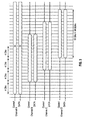
- packets from transmitter T are divided into 64-byte segments for transmission over four channels CHA, CHB, CHC and CHD that are staggered in their phase relationship to one another.
- a first array or set of SERDES (serializer/deserializer) devices TSA, TSB, TSC and TSD at the transmitter T in each channel is used to serialize the data and control for transmission across the midplane/backplane P and a second array or set of SERDES devices RSA, RSB, RSC and RSD are used at the receiver R in each channel to deserialize the data.
- SERDES devices allow data and control to be passed across the midplane/backplane in a compressed manner and thus reduce the large variable amount of latency for a complete packet transfer.
- the channels are staggered by 40 ns and the maximum latency per channel is 20 ns.
- the invention has two basic aspects: the topology of Figure 1 and a bus protocol that runs on that topology to provide the required bandwidth of 10Gbps for variable length packets.
- Each channel includes a plurality of core data path signals, a 32-bit wide data bus with eleven-bits of out-of-band control, and a number of non-core data path signals, which may be used to transfer additional information.
- Packets are broken apart into segments, 64-bytes of data, and transmitted 32-bits per cycle over 16 clock cycles. Packets that are greater than 64 bytes are required to be transmitted over more than one channel.
- SOS Start of Segment
- a Start of Packet (SOP) signal is raised for one clock cycle concurrent with the first word of the packet.
- EOP End of a Packet
- the Empty (MPTY) signals indicate how many bytes of the current word are valid. Since the bus is a word-wide (i.e. 32-bits will be transferred each clock cycle) up to three bytes of PAD may be present on a transfer. The MPTY signals are only valid when an EOP occurs. If the packet happens contain an error, then the Error (ERR) signal becomes active while EOP is active.
- the Valid (VAL) signal is active.
- the parity across this interface should always be valid for both the data path (DPRTY) signal and the control path (CPRTY) signal.
- Figure 3 illustrates the staggering performed by the transmitting device T.
- the invention is directed to the method and apparatus of partitioning packets into segments of predetermined size (for example, 64-bytes), serializing the segments, and transmitting them over a plurality of channels (for example, four) that have a staggered phase relationship to one another, and wherein the phase difference between adjacent channels (actually, adjacent segments in a sequence of segments that form the packet) and more than the maximum latency that can occur in any one channel, thereby maintaining the order of the serialized packet segments.
- the invention is not limited to variable-length packets as the invention can be used for both fixed-length cells and variable-length packets.
- This invention addresses an obstacle and solves the problem that will be encountered by any efforts to pass variable-length packet data between separate cards.
Landscapes
- Engineering & Computer Science (AREA)
- Computer Networks & Wireless Communication (AREA)
- Signal Processing (AREA)
- Power Engineering (AREA)
- Communication Control (AREA)
- Data Exchanges In Wide-Area Networks (AREA)
- Information Transfer Systems (AREA)
Claims (10)
- Verfahren zur Kommunikation von Datenpaketen über eine Midplane oder eine Backplane eines elektronischen Systems, das die folgenden Schritte umfasst:a) Bildung einer Vielzahl von Kanälen über diese Midplane oder Backplane,b) Unterteilen der einzelnen Datenpakete in Segmente einer vordefinierten Größe;c) Serialisieren aller Segmente auf eine vordefinierte Breite;d) Senden aller serialisierten Segmente über eine Midplane oder Backplane an einem entsprechenden Kanal; eine Midplanee) Empfangen serialisierter Segmente, die über die Midplane oder Backplane gelaufen sind, von entsprechendenf) De-Serialisieren der empfangenen serialisierten Segmente; und zum Datenpaket.
- Verfahren gemäß Anspruch 1, wobei dieser Schritt d) den Schritt umfasst zum Verzögern der Übertragung eines Segments in einem Kanal gegenüber der Übertragung in einem Kanal, der ein nächstes sequenzielles Segment des Datenopakets umfasst, sodass die Segment relativ zueinander gestaffelt sind.
- Verfahren gemäß Anspruch 1 oder Anspruch2, wobei Schritt d) des Weiteren das Kenneichen des Packets mit den Außerbandsteuerungs- und den Fehlerkennungs- bzw. -korrectursignalen umfasst.
- Vorrichtung in einem Kommunikationssystem mit einer digitalen Vorrichtung auf der Datensenderseite zum Senden digitaler Datenpakete variabler Länge zwischen zwei separaten Punkten über eine Midplane oder eine Backplane an eine digitale Vorrichtung auf der Datenempfängerseite, wobei diese Midplane bzw. Backplane eine begrenzte Anzahl verfügbarer umfasst:Mittel an diesem digitalen Datensender zum Unterteilen der einzelnen Datenpakete in Segmente einer vordefinierten Größe,eine Anordnung von Serialisierern, die mit dieser sendenden seite verbunden sind, zum Serialisieren der einzelnen Segmente zu einer vordefinierten Breite, wobei jeder Serialisierer mit einem separaten Pfad durch diese Midplane bzw. Backplane verbunden ist,eine Anordnung von Serialisierern an dieser Empfängerseite, deren Anzahl der Anzahl von Serialisierern dieser entsprechenden Senderseite an dieser Midplane bzw. Backplane entspricht, zum Empfangen der über diese Midplane bzw. Backplane gelaufenen serialisierten Datensegmente von der entsprechenden Kanälen, und Mittel zum Wiederzusammensetzen der deserialisierten Datensegmente zum Datenpaket.
- Vorrichtung gemäß Anspruch 4, wobei bei dieser Unterteilung von Paketen in Segmente einer vordefinierten Größe, bei der Serialisierung des Segments und beim Senden dieser Segmente über eine Vielzahl von Kanälen diese Kanäle eine gestaffelte Phasenbeziehung zueinander den angrenzenden Kanälen über die maximale Latenz hinausgeht, die in einem einzelnen Kanal auftreten kann, wodurch die Reihenfolge der serialisierten Paketsegmente erhalten bleicht.
- Vorrichtung gemäß Anspruch 5, wobei diese Datensegmente in 64-Byte-Segmenten angeordnet sind und die Anzahl der Kanäle in dieser Midplane vier beträgt und die Staffelung zwei Mal die maximale Latenz beträgt.
- Vorrichtung gemäß einem der Ansprüche 4 bis 6, wobei diese Übertragung von Segmenten in den entsprechenden Kanälen verzögert ist gegenüber der Übertragung eines Kanals, der ein nächstes sequenzielles Element des Pakets umfasst.
- Vorrichtung gemäß einem der Ansprüche 4 bis 7, die Mittel umfasst zum Kennzeichnen der Pakete mit Außerbandsteuerungs- und Fehlererkennungs- bzw. korrektursignalen.
- Kommunikationssystem mit einer digitalen Vorrichtung an der Senderseite zum Senden digitaler Datenpakete variabler Länge zwischen separaten Karten über eine Midplane oder eine Backplane an eine digitale Vorrichtung an der Empfängerseite, wobei diese Vorrichtung auf der Senderseite Mittel umfasst zum Unterteilen der einzelnen digitalen Datenpakete in Segmente einer vordefinierten größe und eine Anordnung von mit dieser Senderseite verbundenen Serialisierern zum Serialisieren der einzelnen Segmente zu einer vordefinierten Breite, wobei jeder Serialisierer mit einem separaten Pfad durch diese Midplane bzw. Backplane verbunden ist.
- Vorrichtung auf der Empfängerseite in einer Kommunikationssystem mit einer digitalen Datensenderseite zum Senden digitaler Datenpakete variabler Länge zwischen zwei separaten Karten über eine Midplane oder eine Backplane an eine digitale Vorrichtung auf der Datenempfängerseite, wobei diese Vorrichtung auf der Senderseite mehrere Kanäle bildet,
wobei diese Vorrichtung auf dieser Empfängerseite eine Anordnung von Deserialisierern umfasst, deren Anzahl der Anzahl von Serialisierern auf dieser Senderseite entspricht, zum Empfangen der über diese Midplane gelaufenen serialisierten Datensegmente von den entsprechenden Kanälen, und zum Wiederzusammensetzen der deserialisierten Datensegmente zu Datenpaketen.
Applications Claiming Priority (2)
| Application Number | Priority Date | Filing Date | Title |
|---|---|---|---|
| US304797 | 2002-11-27 | ||
| US10/304,797 US7327725B2 (en) | 2002-11-27 | 2002-11-27 | Method and apparatus capable of transferring very high data rates across a midplane or backplane |
Publications (3)
| Publication Number | Publication Date |
|---|---|
| EP1424871A2 EP1424871A2 (de) | 2004-06-02 |
| EP1424871A3 EP1424871A3 (de) | 2006-06-14 |
| EP1424871B1 true EP1424871B1 (de) | 2008-01-09 |
Family
ID=32298043
Family Applications (1)
| Application Number | Title | Priority Date | Filing Date |
|---|---|---|---|
| EP03300227A Expired - Lifetime EP1424871B1 (de) | 2002-11-27 | 2003-11-24 | Verfahren und Apparat zur Übertragung sehr hoher Datenraten über eine Zwischen- oder Rückwandleiterplatte |
Country Status (3)
| Country | Link |
|---|---|
| US (1) | US7327725B2 (de) |
| EP (1) | EP1424871B1 (de) |
| DE (1) | DE60318542T2 (de) |
Families Citing this family (8)
| Publication number | Priority date | Publication date | Assignee | Title |
|---|---|---|---|---|
| US8418129B1 (en) | 2001-12-14 | 2013-04-09 | Qualcomm Incorporated | Method for automatically generating code to define a system of hardware elements |
| US7424013B1 (en) * | 2001-12-20 | 2008-09-09 | Applied Micro Circuits Corporation | System and method for granting arbitrated bids in the switching of information |
| US7352694B1 (en) * | 2001-12-14 | 2008-04-01 | Applied Micro Circuits Corporation | System and method for tolerating data link faults in a packet communications switch fabric |
| US7496818B1 (en) | 2003-02-27 | 2009-02-24 | Marvell International Ltd. | Apparatus and method for testing and debugging an integrated circuit |
| US7444571B1 (en) | 2003-02-27 | 2008-10-28 | Marvell International Ltd. | Apparatus and method for testing and debugging an integrated circuit |
| US7216276B1 (en) * | 2003-02-27 | 2007-05-08 | Marvell International Ltd. | Apparatus and method for testing and debugging an integrated circuit |
| US20050259692A1 (en) | 2004-05-19 | 2005-11-24 | Zerbe Jared L | Crosstalk minimization in serial link systems |
| FR3093198B1 (fr) * | 2019-02-22 | 2021-02-12 | St Microelectronics Grenoble 2 | Transmission de données liées sur bus I2C |
Family Cites Families (10)
| Publication number | Priority date | Publication date | Assignee | Title |
|---|---|---|---|---|
| US5608733A (en) | 1994-11-29 | 1997-03-04 | Valle; Richard | ATM inverse multiplexing |
| US6317433B1 (en) * | 1997-10-16 | 2001-11-13 | Cisco Technology, Inc. | Method and system for optimizing transmission link bandwidth occupation in high speed digital networks |
| IT1307016B1 (it) | 1999-01-27 | 2001-10-11 | Cselt Centro Studi Lab Telecom | Procedimento e dispositivo per la trasmissione di segnali numerici. |
| WO2001020947A1 (de) | 1999-09-16 | 2001-03-22 | Siemens Aktiengesellschaft | Verfahren zum minimieren von atm-zellenspeicher |
| US7342942B1 (en) * | 2001-02-07 | 2008-03-11 | Cortina Systems, Inc. | Multi-service segmentation and reassembly device that maintains only one reassembly context per active output port |
| US7006489B2 (en) * | 2001-02-23 | 2006-02-28 | Santera Systems, Inc. | Voice packet switching system and method |
| US7130276B2 (en) * | 2001-05-31 | 2006-10-31 | Turin Networks | Hybrid time division multiplexing and data transport |
| US6934301B2 (en) * | 2001-07-19 | 2005-08-23 | Eci Telecom Ltd. | Method and apparatus for converting data packets between a higher bandwidth network and a lower bandwidth network |
| US7286570B2 (en) | 2001-11-21 | 2007-10-23 | Alcatel-Lucent Canada Inc | High speed sequenced multi-channel bus |
| US7079528B2 (en) * | 2001-12-13 | 2006-07-18 | International Business Machines Corporation | Data communication method |
-
2002
- 2002-11-27 US US10/304,797 patent/US7327725B2/en not_active Expired - Fee Related
-
2003
- 2003-11-24 EP EP03300227A patent/EP1424871B1/de not_active Expired - Lifetime
- 2003-11-24 DE DE60318542T patent/DE60318542T2/de not_active Expired - Lifetime
Also Published As
| Publication number | Publication date |
|---|---|
| DE60318542D1 (de) | 2008-02-21 |
| DE60318542T2 (de) | 2009-01-22 |
| EP1424871A3 (de) | 2006-06-14 |
| EP1424871A2 (de) | 2004-06-02 |
| US7327725B2 (en) | 2008-02-05 |
| US20040100946A1 (en) | 2004-05-27 |
Similar Documents
| Publication | Publication Date | Title |
|---|---|---|
| US7751411B2 (en) | System interface for cell and/or packet transfer | |
| EP1632103B1 (de) | Paketschnittstellensystem | |
| US5446726A (en) | Error detection and correction apparatus for an asynchronous transfer mode (ATM) network device | |
| KR950005147B1 (ko) | 패킷 통신용 패킷 스위칭 회로망 및 그것에 의한 패킷 스위칭 방법 | |
| US5625825A (en) | Random number generating apparatus for an interface unit of a carrier sense with multiple access and collision detect (CSMA/CD) ethernet data network | |
| US5668809A (en) | Single chip network hub with dynamic window filter | |
| US5784370A (en) | Method and apparatus for regenerating a control signal at an asynchronous transfer mode (ATM) layer or a physical (PHY) layer | |
| US5640399A (en) | Single chip network router | |
| US8385374B1 (en) | Multilane communication device | |
| US5802287A (en) | Single chip universal protocol multi-function ATM network interface | |
| EP1080561B1 (de) | Weiterleitung von paketen mit variabler länge in einem multiport-switch | |
| EP1670199B1 (de) | Entwurf für Kanalausrichtung, Fehlerbehandlung und Taktrouting unter Verwendung von festverdrahteten Blöcken zur Datenübertragung innerhalb von programmierbaren integrierten Schaltungen | |
| US5953345A (en) | Reduced pin-count 10Base-T MAC to transceiver interface | |
| EP1424871B1 (de) | Verfahren und Apparat zur Übertragung sehr hoher Datenraten über eine Zwischen- oder Rückwandleiterplatte | |
| CN109951750B (zh) | 基于FlexE一层交叉架构的数据处理方法及系统 | |
| US8848526B1 (en) | Network processor with traffic shaping response bus interface | |
| US6882661B1 (en) | System for detection of asynchronous packet rates and maintenance of maximum theoretical packet rate | |
| US6611538B1 (en) | Data transmission synchronization system | |
| EP3618317A1 (de) | Nachrichtensendeverfahren und nachrichtenempfangsverfahren und -vorrichtung | |
| US6826187B1 (en) | Interfacing between a physical layer and a bus | |
| KR20010102399A (ko) | 데이터 통신 | |
| US7706417B1 (en) | Method of and circuit for generating a plurality of data streams | |
| US5748917A (en) | Line data architecture and bus interface circuits and methods for dual-edge clocking of data to bus-linked limited capacity devices | |
| US9160604B2 (en) | Systems and methods to explicitly realign packets | |
| US5781544A (en) | Method for interleaving network traffic over serial lines |
Legal Events
| Date | Code | Title | Description |
|---|---|---|---|
| PUAI | Public reference made under article 153(3) epc to a published international application that has entered the european phase |
Free format text: ORIGINAL CODE: 0009012 |
|
| AK | Designated contracting states |
Kind code of ref document: A2 Designated state(s): AT BE BG CH CY CZ DE DK EE ES FI FR GB GR HU IE IT LI LU MC NL PT RO SE SI SK TR |
|
| AX | Request for extension of the european patent |
Extension state: AL LT LV MK |
|
| PUAL | Search report despatched |
Free format text: ORIGINAL CODE: 0009013 |
|
| AK | Designated contracting states |
Kind code of ref document: A3 Designated state(s): AT BE BG CH CY CZ DE DK EE ES FI FR GB GR HU IE IT LI LU MC NL PT RO SE SI SK TR |
|
| AX | Request for extension of the european patent |
Extension state: AL LT LV MK |
|
| 17P | Request for examination filed |
Effective date: 20061214 |
|
| AKX | Designation fees paid |
Designated state(s): DE ES FR GB IT |
|
| GRAP | Despatch of communication of intention to grant a patent |
Free format text: ORIGINAL CODE: EPIDOSNIGR1 |
|
| GRAS | Grant fee paid |
Free format text: ORIGINAL CODE: EPIDOSNIGR3 |
|
| GRAA | (expected) grant |
Free format text: ORIGINAL CODE: 0009210 |
|
| AK | Designated contracting states |
Kind code of ref document: B1 Designated state(s): DE ES FR GB IT |
|
| REG | Reference to a national code |
Ref country code: GB Ref legal event code: FG4D |
|
| REF | Corresponds to: |
Ref document number: 60318542 Country of ref document: DE Date of ref document: 20080221 Kind code of ref document: P |
|
| PG25 | Lapsed in a contracting state [announced via postgrant information from national office to epo] |
Ref country code: ES Free format text: LAPSE BECAUSE OF FAILURE TO SUBMIT A TRANSLATION OF THE DESCRIPTION OR TO PAY THE FEE WITHIN THE PRESCRIBED TIME-LIMIT Effective date: 20080420 |
|
| ET | Fr: translation filed | ||
| PLBE | No opposition filed within time limit |
Free format text: ORIGINAL CODE: 0009261 |
|
| STAA | Information on the status of an ep patent application or granted ep patent |
Free format text: STATUS: NO OPPOSITION FILED WITHIN TIME LIMIT |
|
| 26N | No opposition filed |
Effective date: 20081010 |
|
| PG25 | Lapsed in a contracting state [announced via postgrant information from national office to epo] |
Ref country code: IT Free format text: LAPSE BECAUSE OF FAILURE TO SUBMIT A TRANSLATION OF THE DESCRIPTION OR TO PAY THE FEE WITHIN THE PRESCRIBED TIME-LIMIT Effective date: 20080109 |
|
| REG | Reference to a national code |
Ref country code: FR Ref legal event code: CD Owner name: ALCATEL-LUCENT CANADA INC Effective date: 20130723 |
|
| REG | Reference to a national code |
Ref country code: FR Ref legal event code: GC Effective date: 20130820 |
|
| REG | Reference to a national code |
Ref country code: GB Ref legal event code: 732E Free format text: REGISTERED BETWEEN 20130912 AND 20130918 |
|
| REG | Reference to a national code |
Ref country code: FR Ref legal event code: RG Effective date: 20141015 |
|
| REG | Reference to a national code |
Ref country code: FR Ref legal event code: PLFP Year of fee payment: 13 |
|
| REG | Reference to a national code |
Ref country code: FR Ref legal event code: PLFP Year of fee payment: 14 |
|
| PGFP | Annual fee paid to national office [announced via postgrant information from national office to epo] |
Ref country code: GB Payment date: 20161122 Year of fee payment: 14 Ref country code: FR Payment date: 20161118 Year of fee payment: 14 Ref country code: DE Payment date: 20161121 Year of fee payment: 14 |
|
| REG | Reference to a national code |
Ref country code: DE Ref legal event code: R119 Ref document number: 60318542 Country of ref document: DE |
|
| GBPC | Gb: european patent ceased through non-payment of renewal fee |
Effective date: 20171124 |
|
| REG | Reference to a national code |
Ref country code: FR Ref legal event code: ST Effective date: 20180731 |
|
| PG25 | Lapsed in a contracting state [announced via postgrant information from national office to epo] |
Ref country code: FR Free format text: LAPSE BECAUSE OF NON-PAYMENT OF DUE FEES Effective date: 20171130 Ref country code: DE Free format text: LAPSE BECAUSE OF NON-PAYMENT OF DUE FEES Effective date: 20180602 |
|
| PG25 | Lapsed in a contracting state [announced via postgrant information from national office to epo] |
Ref country code: GB Free format text: LAPSE BECAUSE OF NON-PAYMENT OF DUE FEES Effective date: 20171124 |