EP1424816A2 - Verfahren zum Austausch von Daten zwischen Bluetooth-Geräten - Google Patents
Verfahren zum Austausch von Daten zwischen Bluetooth-Geräten Download PDFInfo
- Publication number
- EP1424816A2 EP1424816A2 EP03024474A EP03024474A EP1424816A2 EP 1424816 A2 EP1424816 A2 EP 1424816A2 EP 03024474 A EP03024474 A EP 03024474A EP 03024474 A EP03024474 A EP 03024474A EP 1424816 A2 EP1424816 A2 EP 1424816A2
- Authority
- EP
- European Patent Office
- Prior art keywords
- transport layer
- base stations
- bluetooth
- several
- hcl0
- Prior art date
- Legal status (The legal status is an assumption and is not a legal conclusion. Google has not performed a legal analysis and makes no representation as to the accuracy of the status listed.)
- Granted
Links
Images


Classifications
-
- H—ELECTRICITY
- H04—ELECTRIC COMMUNICATION TECHNIQUE
- H04W—WIRELESS COMMUNICATION NETWORKS
- H04W8/00—Network data management
- H04W8/26—Network addressing or numbering for mobility support
-
- H—ELECTRICITY
- H04—ELECTRIC COMMUNICATION TECHNIQUE
- H04W—WIRELESS COMMUNICATION NETWORKS
- H04W80/00—Wireless network protocols or protocol adaptations to wireless operation
-
- H—ELECTRICITY
- H04—ELECTRIC COMMUNICATION TECHNIQUE
- H04W—WIRELESS COMMUNICATION NETWORKS
- H04W84/00—Network topologies
- H04W84/18—Self-organising networks, e.g. ad-hoc networks or sensor networks
-
- H—ELECTRICITY
- H04—ELECTRIC COMMUNICATION TECHNIQUE
- H04W—WIRELESS COMMUNICATION NETWORKS
- H04W88/00—Devices specially adapted for wireless communication networks, e.g. terminals, base stations or access point devices
- H04W88/12—Access point controller devices
Definitions
- the invention relates to a method for exchanging data in a wireless Communication system between several application programs on one Bluetooth server and several mobile devices over several base stations, which are each connected to the Bluetooth server, according to the preamble of Claim 1.
- Radio network infrastructures based on Bluetooth technology exist in Generally from base stations, so-called Bluetooth access points (BAP), and possibly from a server that the access of mobile devices to the System resources centrally controlled and coordinated, with the base stations and the server is usually connected via a local IP network (LAN).
- BAP Bluetooth access points
- LAN local IP network
- each base station implements all layers of the Bluetooth protocol stack and thus works as an independent LAN access point in one decentralized system.
- each base station controls independently of the others own physical and logical connections, whereby the Connection control of the physical connections in the lower layers of the Bluetooth protocol stack (Lower Layer Stack) and that of the logical in the upper layers (upper layer stack).
- Another option is to split the protocol layers on the base station and a central server. Only those are still running in the base stations lower Bluetooth protocol layers. In a central server (Bluetooth server) the upper protocol layers of the individual base stations run. On The key advantage here is that the base stations are relatively inexpensive are to be produced, since in addition to the required Bluetooth hardware, only one Interface to the central server is necessary.
- Bluetooth wireless Communication
- the object of the invention is to provide a flexible Bluetooth protocol architecture create a variety of base stations with a central station can be connected.
- the solution according to the invention is based on only the base stations (BAP) to implement lower protocol layers of the Bluetooth standard and on the Central station (BOS) only a single instance of the upper protocol layers to set up.
- BAP base stations
- BOS Central station
- BOS Bluetooth Operating Server
- the inventive method for exchanging data in a wireless Communication system between several application programs on one Bluetooth server and several mobile devices over several base stations, which are each connected to the Bluetooth server, with a transport layer with an upper transport layer in the Bluetooth server and one each lower transport layer in each of the multiple base stations to manage the Connection between one of the several application programs and one of the is arranged several base stations, is characterized in that each of the several application programs on a common upper transport layer accesses and a host controller management unit under the top Transport layer is arranged in the Bluetooth server, the multiple host controller sub-instances has, each of a lower transport layer is assigned to the multiple base stations so that each of the multiple Application programs can be connected to several base stations.
- each of the several base stations receives a physical address and is each of the multiple mobile terminals from each of the multiple Application programs assigned a logical address so that the physical address of each of the multiple base stations with the logical address links each of the plurality of mobile terminals in a logic connection layer which is arranged above the upper transport layer in the Bluetooth server.
- the logical address of the one of the several mobile devices is preferably used Terminal devices if there is a physical connection between one of the several base stations and one of the several end devices is dismantled and a physical connection between another one of the several Base stations and one of the several terminals is set up.
- data is exchanged between the upper transport layer and the lower transport layer via a local data network, in particular an Ethernet or an ISDN S 0 or ISDN UP n connection.
- a local data network in particular an Ethernet or an ISDN S 0 or ISDN UP n connection.
- Data is exchanged between the upper transport layer and the lower transport layer preferably over a local data network encrypted.
- the exchange of Voice data between the upper transport layer and the lower one Transport layer takes place via a UDP / IP socket and the exchange of other data between the upper transport layer and the lower Transport layer takes place via a TCP / IP socket.
- the upper transport layer and the lower transport layer in exchanged a wake-up signal at regular intervals.
- the network infrastructure is simple and therefore can be built inexpensively.
- conventional Bluetooth base stations are only the lower layers in the proposed architecture of the Bluetooth protocol stack implemented. These usually run as Firmware on the Bluetooth baseband chip.
- the base station therefore only consists of a Bluotooth module and an interface, via which the module with the Bluetooth central station can be connected (e.g. Ethernet, USB or Others).
- the invention thus enables very simple, small and inexpensive Solutions for the Bluetooth base stations.
- the system easy to manage Since it is a central system with all logical connections controlled by the Bluetooth central station is at the system only needs administration at this one point, one Administration of each individual station with double data storage is not required.
- the architecture allows additional Bluetooth radios in a simple manner to be installed in a base station and so to a so-called multi-radio base station expand without multiple instances of the top layers of the Bluetooth protocol stack are required. That means capacity can be expanded with very little effort.
- On Handover in which the connection between a mobile device and a first base station dismantled and rebuilt to another base station using the architecture according to the invention can be considerable be accelerated, since only the physical connection now and then must be built. All logical connections over this physical connection running, remain in the central station (Bluetooth server) preserved and are only for the time of changing the physical connection interrupted.
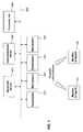
- Fig. 1 shows a Bluetooth system with a central Bluetooth server after State of the art.
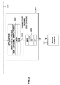
- Fig. 2 shows the structure of software and hardware in a base station after the State of the art.
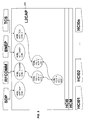
- Fig. 3 shows the structure of software and hardware when dividing the Transport layer on a base station and a Bluetooth server according to the state of the technique.
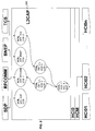
- Fig. 4 shows the structure of software and hardware when dividing the Transport layer on a base station and a Bluetooth server according to the Invention.
- Fig. 5 shows the structure of software and hardware when dividing the Transport layer on a base station, a multi-radio base station and one Bluetooth server according to the invention.
- FIG 6 shows the structure of the L2CAP layer according to the invention.
- Fig. 1 the architecture of a Bluetooth system is shown. Between one mobile terminal 101, 102 (for example a portable computer) and one of several base stations 201, 202, 203, 204 one should Communication connection can be established. On each of the base stations 201, 202, 203, 204 any application programs can run, or the Base stations 201, 202, 203, 204 can, as shown, via a Transport medium 300 to be connected to higher-level servers 401, 402, 403.
- a Transport medium 300 to be connected to higher-level servers 401, 402, 403.
- the communication of the application programs on the base station 201 with the mobile terminals 101, 102 is via a Bluetooth protocol stack processed, which is shown in Fig. 2.
- the Bluetooth protocol stack divides into an upper and a lower protocol stack.
- the top protocol stack 2001 comprises a first layer which, for example, provides a protocol and Service Discovery Protocol (SDP) detection, an emulation of a serial interface via Bluetooth (RFCOMM), a protocol for the transmission of Ethernet packets via Bluetooth (Bluetooth Network Encapsulation Protocol, BNEP) and a protocol for signaling telephone calls (telephony Control and Signaling, TCS) contains.
- SDP protocol and Service Discovery Protocol
- RFIDM emulation of a serial interface via Bluetooth
- BNEP Bluetooth Network Encapsulation Protocol
- TCS Telephony Control and Signaling
- the second protocol layer is a layer for managing the logical Channels and for protocol multiplexing (Logical Link Control and Adaptation Protocol, L2CAP). This includes a first host controller interface layer or upper transport layer HCl0
- This upper protocol stack 2001 is in the base station 201 as software implemented, as well as the overlying application programs that are here not explained further.
- the communication between the upper and the lower protocol stack takes place that is, via the upper transport layer HCl0 and the lower transport layer HCl1.
- the application programs can be shared with others via the transport medium 300 Application programs communicate.
- a connection of a Application program on one of the base stations 201, 202, ... with up to seven mobile terminals 101, 102, ... are manufactured.
- the base stations 101, 102, ... can offer various Bluetooth services (application programs), such a service being access to an Internet / Intranet server 402 or may include other computers 403 that communicate via the transport medium 300 (e.g., a Local Area Network, LAN) are connected to the base stations 101.
- the base stations 101 via the transport medium 300 with a central one Bluetooth server (Bluetooth Operating Server, BOS) 401 connected.
- the central one In turn, server 401 can also offer various Bluetooth services.
- Fig. 3 shows the Bluetooth protocol layers when they are on the central server 401 and base stations, for example stations 201 to 204 become.
- the upper protocol layers are in this division as software in the central server 401 implemented.
- Running to every connected base station an instance 4001, 4002, 4003, 4004 as the upper protocol layer in the central server 401.
- the upper protocol layer instances 4001 to 4004 communicate with the Base stations 201 to 204 via the transport medium 300, via which the HCl interface is realized.
- Each base station 201 to 204 is exactly one instance of the Assigned to upper protocol layers, the base station 201 is the instance 4001 assigned to the upper protocol layers, the base station 202 is the instance 4002 assigned to the upper protocol layers, etc.
- protocol stack splitting 3 modified according to the invention in such a way as shown in FIG. 4 and in following is described.
- FIG. 4 shows the division of the Bluetooth protocol layers according to the invention the Bluetooth server and the base stations 201, 202, ... 20n.
- the bluetooth server 401 any application programs run. Communication between Application programs of one of the mobile terminals 101, 102, 103 and the Application programs of the central station 401 run over a Bluetooth protocol stack.
- the upper Bluetooth protocol stack explained in connection with FIG. 2 divides into an upper stack section 4010 and a lower one Stack section 4020.
- Top stack section 4010 contains applications and Bluetooth profiles.
- SDP provision and Service Discovery Protocol
- RCOMM protocol for the provision and Service Discovery Protocol
- BNEP Bluetooth Network Encapsulation Protocol
- TCS protocol for signaling telephone calls
- L2CAP host controller Interface layer
- a central host becomes in the lower stack section 4020 Controller Management Unit (HCM) inserted, the single one, below it arranged host controller instances HCl01, HCl02, ... HCl0n controls.
- HCM Controller Management Unit
- This Sub-instances HCl01, HCl02, ... HCl0n manage the data exchange and the Distribution of the data with the individual base stations 201, 202, ... 20n.
- All the protocol layers mentioned are software in the Bluetooth server 401 implemented.
- the Bluetooth server 401 communicates with base stations 201, 202, ... 20n via the transport medium 300 via which the HCl interface is implemented.
- the Base stations 201, 202, ... 20n is the lower protocol stack with the Protocol layer for managing the physical channels (Link Manager Protocol, LMP), the link control (baseband, BB) and the Bluetooth radio connection part (RF) implemented, preferably again as firmware.
- LMP Link Manager Protocol
- BB link control
- RF Bluetooth radio connection part
- Each base station 201, 202, ... 20n is exactly one host controller instance assigned, base station 201 is host controller instance HCl01 assigned, the base station 202 is the host controller instance HCl02 assigned, etc.
- multi-radio base stations can also be used be used in a Bluetooth network.
- a multi-radio station is shown in Fig. 5 and designated 501. It consists of two or more Bluetooth radio modules, two of which, namely 5011 and 5012 in 5 are shown.
- the 5 as conventional, simple base stations referred to, one of which is shown with 50n is shown.
- the two Bluetooth radio modules of the multi-radio base station 501 namely 5011 and 5012, communicate with the upper protocol stack 401 via the transport medium 300, each with its own lower transport layer for HCl11 or HCl12 for have the connection with the transport medium 300.
- the division of the Bluetooth protocol according to FIG. 5 possible multiple instances of the lower layers in the base stations 501, ... 50n over the HCl layers with an instance in the upper protocol stack 4010 to communicate. Because the L2CAP layer in the top protocol stack 4010 the conversion of the logical data channels to the physical channels controlled, this must be from the existence of multiple instances of the lower Know protocol layers.
- the physical data channels (asynchronous Connectionless Link (ACL) are within the L2CAP layer of Manage link control blocks (LCB). So everyone is Connection control block through a unique combination of physical Distinguish channel and logical connection from the others. Theoretically there can be any number of connection control blocks and thus on give physical connections. However, the prerequisite is that the maximum The number specified by the Bluetooth specification has not been exceeded becomes.
- connection establishment and communication path through the L2CAP layer and the assignment of the ACL data to a host controller instance HCl01, HCl02, ..., HCl0n is explained below with reference to FIGS. 4 and 6.
- Each Bluetooth protocol SDP, RFCOMM, BNEP and TCS is assigned an application control block (Application Control Block) ACB 1 , ACB 2 , ACB 3 , ACB 4 .
- Application Control Block Application Control Block
- These application control blocks ACB 1 , ACB 2 , ACB 3 , ACB 4 are created by the L2CAP layer when the application software is started. There are no other control blocks after starting the software; they are only set up when a connection is established. The connection establishment and the setting up of further control blocks is described below.
- a mobile terminal 101 wants to perform a service query on the service station (Service Discovery Protocol) SDP on the central station 401, this terminal first establishes a physical ACL connection to a suitable base station, for example to the base station 201.
- the structure of this physical ACL connection is controlled via the Link Manager Protocol (LMP).
- LMP Link Manager Protocol
- ACL 1 a unique identifier for identifying the physical connection is assigned by the LMP layer of the base station 201.
- This ACL identifier is made known to the upper protocol layers by the notification of the HCl layer "HCl Connection Complete".
- This HCl message is transmitted by the host controller instance HCl01 assigned to the base station 201.
- the HCl layer informs the L2CAP layer of the physical connection establishment, whereupon the L2CAP layer creates or allocates an associated link control block (Link Control Block) LCB 1 , which contains the ACL identifier 1 and a base station identifier BAP 101.
- Link Control Block link control Block
- the base station identifier BAP 101 states that the connection control block LCB 1 is linked to the base station BAP 201 via the host controller instance HCl01.
- the mobile device now wants to start the service query and must therefore set up a logical L2CAP channel beforehand. To do this, it sends the L2CAP protocol message "L2CAP_ConnectReq", which contains information such as "PSM” and "Source CID”.
- the source identification (Source CID) is the logical channel identifier of the mobile terminal 101, ie the remote station. This identifier is referred to in the L2CAP layer of the central station as remote CID (remote CID) r 1 .
- the L2CAP layer 602 answers the message with the protocol message "L2CA_ConnectRsp", in which the remote station 101 is informed of the local CID (local CID), the assigned logical channel identifier of the central station.
- the number of logical channel identifiers CID is limited by the range of values that can be assigned according to the Bluetooth specification (0000h - FFFFh).
- the L2CAP layer now creates a channel control block CCB 1 , which links the connection control block LCB 1 with the application control block of SDP ACB 1 .
- the information "remote CID" r 1 and "local CID” I 1 and a link to LCB 1 and ACB 1 are stored in this channel control block CCB 1 .
- the link to the channel control block CCB 1 is stored in reverse in ACB 1 and LCB 1 .
- the mobile terminal 101 If the mobile terminal 101 now also wants to use the service of the serial interface emulation RFCOMM, it sets up another logical L2CAP channel. This logical channel runs over one and the same physical connection and thus over the connection control block LCB 1 .
- the channel control block CCB 2 is created, which connects the connection control block LCB 1 to the desired application control block ACB 2 .
- a second mobile terminal 102 can now simultaneously communicate with the server 401 via the same base station 201.
- a second connection control block LCB 2 is generated, which is assigned to the base station BAP 201 via the host controller instance HCl01.
- the mobile terminal can now use the RFCOMM service.
- a logical channel, identified by the CCB 3 channel control block, is again set up.
- a third mobile terminal 103 would like to communicate with the Bluetooth server 401 via another base station 202, for example.
- a connection control block LCB 4 is now generated, which is assigned to the base station BAP 202 via the host controller instance HCl02.
- the mobile terminal 103 can now also use the RFCOMM service.
- a logical channel is set up, which is identified by the CCB 5 channel control block.
- FIGS. 7, 8 and 9 Such a handover from the point of view of the L2CAP layer in the Bluetooth server is shown in FIGS. 7, 8 and 9.
- a connection between a mobile terminal 101 and the Bluetooth server 401 via the base station 201 In FIG. 7 it can be seen that this physical connection runs via the host controller instance HCl01 from BAP 201.
- the mobile terminal 101 uses the services RFCOMM and TCS, with which it is connected via two logical L2CAP channels, namely CCB 1 and CCB 2 .
- the mobile terminal 101 would like to switch from base station 201 to base station 202.
- the physical connection between the mobile terminal 101 and the base station 201 is cleared down according to the invention, but without clearing the logical L2CAP channels.
- 8 shows that the logical L2CAP channels now temporarily end in the connection control block LCB 1 , since the physical connection is missing.
- a physical connection is now established between the mobile terminal 101 and the base station 202.
- the change of the base station is carried out in a very simple manner: from FIG. 9 it can be seen that the information of the new physical connection is stored in the still existing connection control block LCB 1 .
- the logical channels of RFCOMM and TCS now run via the host controller instance HCl02 and thus via base station 202.
- an Ethernet is used as the transport medium between the upper transport layer and the lower transport layer, but an ISDN S 0 or ISDN UP n connection can also be used just as well.
- Voice and other data transmitted according to their nature will the language on the air interface via SCO (synchronous connection oriented link) transfer connections.
- Each base station can have a maximum of three SCO connections build up.
- the voice data between the base station and the server an RTP (Real Time Protocol) header for "Voice over IP Telephony".
- the voice data is then transmitted via a UDP / IP socket, whereby it there are a total of three UDP sockets per base station for three SCO voice channels.
- a TCP / IP socket is used for Protocol messages (HCl commands and events) between upper and lower Transport layer used.
- Another TCP / IP socket is used for ACL (Asynchronous Connectionless Link) data used.
- ACL Asynchronous Connectionless Link
- the RTP endpoints can be on the base station and on the Server, or the RTP endpoints are on the base station and on the remote subscriber (subscriber of Voice over IP telephony).
- the route between the base station and server can be encrypted be, preferably ARC4 or SSL is used for encryption.
- connection between the host processor of a base station and the host controller (Bluetooth module) of the base station via a "keep-alive" mechanism supervised. This can lead to incorrect behavior of the individual components (e.g. crash) are recognized immediately, and countermeasures can be initiated immediately. This increases system stability and reliability.
- each Bluetooth host controller has one limited buffer for buffering ACL and SCO data packets. It there is a flow control between the host controller and the host. Whenever one The host controller sends the data packet successfully to the host a message (HCl Number of Completed Packets) in which the host receives the number the packets sent are communicated. The host then knows how many new ones Packets he can send to the host controller.
- the disadvantage with this state of the Technology is that when it is transmitted via the transport medium comparatively long term can elapse. So the buffers become very underutilized, because between the message (HCl Number of Completed Packets) from the host controller to the host and sending a new one Package can be a relatively long period of time.
- an additional buffer is set up in the base station much larger than the buffer of the Bluetooth host controller (Bluetooth module) is.
- Bluetooth host controller Bluetooth module
- the physical address of each of the plurality of base stations 201, 202, ..., 20n assigned one or more of the following: a system name, one Manufacturer's product name, a unique base station identifier.
- the Bluetooth server shares each of its base stations Bluetooth name (Bluetooth Device Name) with. This sits down in his complete version as follows: ⁇ system name>, ⁇ manufacturer> - ⁇ product name> and ⁇ unique base station identifier>.
- the Base station of the server for example the address: "Test system, Tenovis - AP, Room 103 ".
- the system name is for all base stations of the Bluetooth system same, but the unique base station identifier differs.
- the mobile End devices can then search specifically for the system name and so on recognize which base stations belong to their own Bluetooth system.
- the physical address of each of the several Base stations 201, 202, ..., 20n correspond to one or more of the following Specifications: a system name, a manufacturer's product name, a unique one Base station identifier. This ensures that the assignment of each of the several host controller sub-instances HCl01, HCl02, ... each with a lower one Transport layer HCl11, HCl12, ..., HCl1n on the several base stations 201, 202, ..., 20n can take place according to one or more of these details.
Landscapes
- Engineering & Computer Science (AREA)
- Databases & Information Systems (AREA)
- Computer Networks & Wireless Communication (AREA)
- Signal Processing (AREA)
- Mobile Radio Communication Systems (AREA)
- Small-Scale Networks (AREA)
Abstract
Description
- 101, 102, 103, 104
- mobiles Endgerät
- 201, 202, 203, 204
- Basisstation
- 300
- Transportmedium
- 401,402,403
- Server: Bluetooth- Server, Internet/Intranet- Server, Rechner
- 2001
- oberer Protokollstapel
- 2002
- unterer Protokollstapel
- 2003
- Schnittstelle zwischen oberem und unterem Protokollstapel
- 4001, 4002, 4003, 4004
- Protokollstapel, die jeweils den Datenaustausch zwischen einem Applikationsprogramm und einer Basisstation ermöglichen
- 4010
- oberer Stapelabschnitt des oberen Protokollstapels
- 4020
- unterer Stapelabschnitt des oberen Protokollstapels
- 501
- Multiradio- Basisstation
- 5011
- erstes Funkverbindungselement der Multiradio-Basisstation
- 5012
- zweites Funkverbindungselement der Multiradio-Basisstation
Claims (8)
- Verfahren zum Austausch von Daten in einem drahtlosen Kommunikationssystem zwischen mehreren Applikationsprogrammen auf einem Bluetooth- Server (401) und mehreren mobilen Endgeräten (101, 102, ...) über mehrere Basisstationen (201, 202, ..., 20n), die jeweils mit dem Bluetooth- Server (401) verbunden sind,
wobei eine Transportschicht mit einer oberen Transportschicht (HCl0) in dem Bluetooth- Server (401) und jeweils einer unteren Transportschicht (HCl11, HCl12, ..., HCl1n) in jeder der mehreren Basisstationen (201, 202, ..., 20n) zum Verwalten der Verbindung zwischen einem der mehreren Applikationsprogramme und einer der mehreren Basisstationen (201, 202, ..., 20n) angeordnet ist,
dadurch gekennzeichnet, dass
jedes der mehreren Applikationsprogramme auf eine gemeinsame obere Transportschicht (HCl0) zugreift und
eine Host-Controller-Management-Einheit (HCM) unter der oberen Transportschicht (HCl0) in dem Bluetooth- Server (401) angeordnet ist, die mehrere Host-Controller-Subinstanzen (HCl01, HCl02, ...) aufweist, die jeweils einer unteren Transportschicht (HCl11, HCl12, ..., HCl1n) auf den mehreren Basisstationen (201, 202, ..., 20n) zugeordnet ist, so dass jedes der mehreren Applikationsprogramme mit mehreren Basisstationen (201, 202, ..., 20n) verbunden sein kann. - Verfahren nach Anspruch 1, bei dem jede der mehreren Basisstationen (201, 202, ..., 20n) eine physikalische Adresse aufweist und jedem der mehreren mobilen Endgeräte (101, 102, ...) von jedem der mehreren Applikationsprogramme eine logische Adresse zugeordnet ist,
dadurch gekennzeichnet, dass
die physikalische Adresse jeder der mehreren Basisstationen (201, 202, ..., 20n) mit der logischen Adresse jedes der mehreren mobilen Endgeräte (101, 102, ...) in einer Logikverbindungsschicht (L2CAP) verknüpft wird, die über der oberen Transportschicht (HCl0) in dem Bluetooth- Server (401) angeordnet ist. - Verfahren nach Anspruch 2,
dadurch gekennzeichnet, dass
der physikalischen Adresse jeder der mehreren Basisstationen (201, 202, ..., 20n) eine oder mehrere der folgenden Angaben entspricht: ein Systemname, eine Hersteller- Produktbezeichnung, eine eindeutige Basisstationskennung, so dass die Zuordnung jeder der mehreren Host-Controller-Subinstanzen (HCl01, HCl02, ...) zu jeweils einer unteren Transportschicht (HCl11, HCl12, ..., HCl1n) auf den mehreren Basisstationen (201, 202, ..., 20n) nach einer oder mehren dieser Angaben erfolgt. - Verfahren nach Anspruch 2 oder 3,
dadurch gekennzeichnet, dass
die logische Adresse des einen der mehreren mobilen Endgeräte (101, 102, ...) beibehalten wird, wenn eine physikalische Verbindung zwischen einer der mehreren Basisstationen (201, 202, ..., 20n) und einem der mehreren Endgeräte (101, 102, ...) abgebaut wird und eine physikalische Verbindung zwischen einer anderen der mehreren Basisstationen (201, 202, ..., 20n) und dem einen der mehreren Endgeräte (101, 102, ...) aufgebaut wird. - Verfahren nach einem der vorangehenden Ansprüche,
dadurch gekennzeichnet, dass
der Austausch von Daten zwischen der oberen Transportschicht (HCl0) und der unteren Transportschicht (HCl1) über ein lokales Datennetz, insbesondere eine Ethernet-, eine ISDN- S0- oder ISDN- UPn- Verbindung, erfolgt. - Verfahren nach Anspruch 5,
dadurch gekennzeichnet, dass
der Austausch von Daten zwischen der oberen Transportschicht (HCl0) und der unteren Transportschicht (HCl1) über ein lokales Datennetz verschlüsselt erfolgt. - Verfahren nach einem der vorangehenden Ansprüche,
dadurch gekennzeichnet, dass
der Austausch von Sprachdaten zwischen der oberen Transportschicht (HCl0) und der unteren Transportschicht (HCl1) über einen UDP/IP- Socket erfolgt und der Austausch von sonstigen Daten zwischen der oberen Transportschicht (HCl0) und der unteren Transportschicht (HCl1) über einen TCP/IP- Socket erfolgt. - Verfahren nach einem der vorangehenden Ansprüche,
dadurch gekennzeichnet, dass
zwischen der oberen Transportschicht (HCl0) und der unteren Transportschicht (HCl1) in regelmäßigen Zeitabständen ein Wecksignal (keep alive) ausgetauscht wird.
Applications Claiming Priority (2)
| Application Number | Priority Date | Filing Date | Title |
|---|---|---|---|
| DE10255341 | 2002-11-27 | ||
| DE2002155341 DE10255341B3 (de) | 2002-11-27 | 2002-11-27 | Verfahren zum Austausch von Daten zwischen Bluetooth-Geräten |
Publications (3)
| Publication Number | Publication Date |
|---|---|
| EP1424816A2 true EP1424816A2 (de) | 2004-06-02 |
| EP1424816A3 EP1424816A3 (de) | 2010-03-31 |
| EP1424816B1 EP1424816B1 (de) | 2013-03-06 |
Family
ID=32087363
Family Applications (1)
| Application Number | Title | Priority Date | Filing Date |
|---|---|---|---|
| EP20030024474 Expired - Lifetime EP1424816B1 (de) | 2002-11-27 | 2003-10-23 | Verfahren zum Austausch von Daten zwischen Bluetooth-Geräten |
Country Status (2)
| Country | Link |
|---|---|
| EP (1) | EP1424816B1 (de) |
| DE (1) | DE10255341B3 (de) |
Families Citing this family (1)
| Publication number | Priority date | Publication date | Assignee | Title |
|---|---|---|---|---|
| FI20096156L (fi) * | 2009-11-06 | 2011-05-07 | Bluegiga Technologies Oy | Simplifioitu Bluetooth -liityntäpiste |
Family Cites Families (2)
| Publication number | Priority date | Publication date | Assignee | Title |
|---|---|---|---|---|
| CA2376592A1 (en) * | 2000-06-13 | 2001-12-20 | Nick Moss | Distributed bluetooth communications network |
| US6996085B2 (en) * | 2000-12-22 | 2006-02-07 | Nortel Networks Limited | System, device, and method for providing network access in a communication system |
-
2002
- 2002-11-27 DE DE2002155341 patent/DE10255341B3/de not_active Expired - Fee Related
-
2003
- 2003-10-23 EP EP20030024474 patent/EP1424816B1/de not_active Expired - Lifetime
Non-Patent Citations (1)
| Title |
|---|
| None |
Also Published As
| Publication number | Publication date |
|---|---|
| DE10255341B3 (de) | 2004-05-06 |
| EP1424816B1 (de) | 2013-03-06 |
| EP1424816A3 (de) | 2010-03-31 |
Similar Documents
| Publication | Publication Date | Title |
|---|---|---|
| DE60220246T2 (de) | Verfahren und Vorrichtung zur effizienten Nutzung der Kommunikationsressourcen in einem Datenkommunikationssystem im Überlast-Zustand | |
| DE69434896T2 (de) | Zugriffsverfahren auf ein drahtloses lokales ad-hoc Netzwerk über ein zellulares Weitbereichnetzwerk mit Koppelung des LAN-MAC-Paketkopfes. | |
| DE19950653B4 (de) | Verfahren zum Betreiben eines Mobilfunknetzes | |
| EP1826956B1 (de) | Anpassung von virtuellen und physikalischen Netzwerkschnittstellen | |
| DE60213280T2 (de) | Sicherheitsumkonfiguration in einem universellen mobiltelekommunikationssystem | |
| DE60108927T2 (de) | Komputersysteme, insbesondere virtuelle private Netzwerken | |
| DE3854705T2 (de) | Vorrichtung zum Aufbau und Steuern virtueller Netze. | |
| DE60026006T2 (de) | System zum Empfang von Mehrfachdaten | |
| DE60036466T2 (de) | Verfahren und system zum bereitstellen von diensten an mobilstationen im aktivzustand | |
| WO2003039167A1 (de) | Verfahren und ein mobil-kommunikationsnetz zur bereitstellung von multicast- und/oder broadcastdiensten | |
| DE60214399T2 (de) | Endgeräte, die so ausgelegt sind, dass sie als relaisserver zum verteilen von paketen in einem client-server-netzwerk wirken | |
| EP3503628B1 (de) | Bootstrap-server und verfahren zum aufbauen einer roaming-verbindung über einen bootstrap-server | |
| WO2023247300A1 (de) | Kommunikationssystem, insbesondere 5g system | |
| EP1388996A1 (de) | Verfahren und Anordnung zum Steuern einer Konferenzschaltung in einem paketorientierten Kommunikationsnetz | |
| EP1540985B1 (de) | Verfahren zur durchführung einer übergabeprozedur in einem funkkommunikationssystem für eine paketvermittelte verbindung und dafür angepasstes funkkommunikationssystem | |
| DE10255341B3 (de) | Verfahren zum Austausch von Daten zwischen Bluetooth-Geräten | |
| DE10064107A1 (de) | Verfahren zum Verteilen einer Gruppennachricht in einem Funkkommunikationssystem sowie zugehöriges Funkkommunikationssystem | |
| WO2003013098A1 (de) | Verfahren zur unterstützung mehrerer prüfsummenalgorithmen in einem netzknoten | |
| DE10103103B4 (de) | Verfahren und Vorrichtung zum Wechsel einer mobilen Station zwischen zwei Basisstationen | |
| DE102005005712A1 (de) | Verfahren zur Anpassung einer Verbindung zwischen einem Diensteanbieter und einem Kommunikationsgerät und entsprechendes Kommunikationssystem | |
| EP1313289A2 (de) | Verfahren zur Übertragung von Rückkanal-Daten in einer Verbindung zwischen einem Endgerät und einem Server eines Paketvermittlungsnetzes | |
| DE102020117565A1 (de) | Mobilfunk-Kommunikationsgerät mit zwei zeitgesteuerten integrierten Teilnehmer-Identiftätsmodulen | |
| DE19833069A1 (de) | Verfahren zur Verbindung von Endgeräten mit externen Modems | |
| EP1293098B1 (de) | Mobilfunk-kommunikationssystem und betriebsverfahren dafür | |
| WO2003036995A2 (de) | Verfahren zur durchführung von augenblicklichem nachrichtenverkehr (instant messaging) mit paketvermittelten daten |
Legal Events
| Date | Code | Title | Description |
|---|---|---|---|
| PUAI | Public reference made under article 153(3) epc to a published international application that has entered the european phase |
Free format text: ORIGINAL CODE: 0009012 |
|
| AK | Designated contracting states |
Kind code of ref document: A2 Designated state(s): AT BE BG CH CY CZ DE DK EE ES FI FR GB GR HU IE IT LI LU MC NL PT RO SE SI SK TR |
|
| AX | Request for extension of the european patent |
Extension state: AL LT LV MK |
|
| PUAL | Search report despatched |
Free format text: ORIGINAL CODE: 0009013 |
|
| AK | Designated contracting states |
Kind code of ref document: A3 Designated state(s): AT BE BG CH CY CZ DE DK EE ES FI FR GB GR HU IE IT LI LU MC NL PT RO SE SI SK TR |
|
| AX | Request for extension of the european patent |
Extension state: AL LT LV MK |
|
| RIC1 | Information provided on ipc code assigned before grant |
Ipc: H04L 29/08 20060101ALI20100225BHEP Ipc: H04L 12/28 20060101ALI20100225BHEP Ipc: H04L 12/56 20060101AFI20040318BHEP |
|
| 17P | Request for examination filed |
Effective date: 20100908 |
|
| 17Q | First examination report despatched |
Effective date: 20101020 |
|
| AKX | Designation fees paid |
Designated state(s): DE GB |
|
| REG | Reference to a national code |
Ref country code: DE Ref legal event code: R079 Ref document number: 50314711 Country of ref document: DE Free format text: PREVIOUS MAIN CLASS: H04L0012560000 Ipc: H04W0008260000 |
|
| GRAP | Despatch of communication of intention to grant a patent |
Free format text: ORIGINAL CODE: EPIDOSNIGR1 |
|
| RIC1 | Information provided on ipc code assigned before grant |
Ipc: H04W 88/12 20090101ALN20120905BHEP Ipc: H04W 8/26 20090101AFI20120905BHEP Ipc: H04L 29/08 20060101ALN20120905BHEP Ipc: H04W 84/18 20090101ALN20120905BHEP Ipc: H04W 80/00 20090101ALN20120905BHEP |
|
| GRAS | Grant fee paid |
Free format text: ORIGINAL CODE: EPIDOSNIGR3 |
|
| GRAA | (expected) grant |
Free format text: ORIGINAL CODE: 0009210 |
|
| AK | Designated contracting states |
Kind code of ref document: B1 Designated state(s): DE GB |
|
| REG | Reference to a national code |
Ref country code: GB Ref legal event code: FG4D Free format text: NOT ENGLISH |
|
| REG | Reference to a national code |
Ref country code: DE Ref legal event code: R096 Ref document number: 50314711 Country of ref document: DE Effective date: 20130502 |
|
| PLBE | No opposition filed within time limit |
Free format text: ORIGINAL CODE: 0009261 |
|
| STAA | Information on the status of an ep patent application or granted ep patent |
Free format text: STATUS: NO OPPOSITION FILED WITHIN TIME LIMIT |
|
| PGFP | Annual fee paid to national office [announced via postgrant information from national office to epo] |
Ref country code: GB Payment date: 20131022 Year of fee payment: 11 Ref country code: DE Payment date: 20131024 Year of fee payment: 11 |
|
| 26N | No opposition filed |
Effective date: 20131209 |
|
| REG | Reference to a national code |
Ref country code: DE Ref legal event code: R097 Ref document number: 50314711 Country of ref document: DE Effective date: 20131209 |
|
| REG | Reference to a national code |
Ref country code: DE Ref legal event code: R119 Ref document number: 50314711 Country of ref document: DE |
|
| GBPC | Gb: european patent ceased through non-payment of renewal fee |
Effective date: 20141023 |
|
| PG25 | Lapsed in a contracting state [announced via postgrant information from national office to epo] |
Ref country code: GB Free format text: LAPSE BECAUSE OF NON-PAYMENT OF DUE FEES Effective date: 20141023 Ref country code: DE Free format text: LAPSE BECAUSE OF NON-PAYMENT OF DUE FEES Effective date: 20150501 |