EP1424771A1 - Cascode power amplifier particularly for use in radiofrequency applications - Google Patents
Cascode power amplifier particularly for use in radiofrequency applications Download PDFInfo
- Publication number
- EP1424771A1 EP1424771A1 EP02425729A EP02425729A EP1424771A1 EP 1424771 A1 EP1424771 A1 EP 1424771A1 EP 02425729 A EP02425729 A EP 02425729A EP 02425729 A EP02425729 A EP 02425729A EP 1424771 A1 EP1424771 A1 EP 1424771A1
- Authority
- EP
- European Patent Office
- Prior art keywords
- power amplifier
- transistor
- active element
- amplifier according
- voltage
- Prior art date
- Legal status (The legal status is an assumption and is not a legal conclusion. Google has not performed a legal analysis and makes no representation as to the accuracy of the status listed.)
- Withdrawn
Links
- 230000015556 catabolic process Effects 0.000 description 6
- 230000004913 activation Effects 0.000 description 2
- 238000005516 engineering process Methods 0.000 description 2
- 230000010354 integration Effects 0.000 description 2
- XUIMIQQOPSSXEZ-UHFFFAOYSA-N Silicon Chemical compound [Si] XUIMIQQOPSSXEZ-UHFFFAOYSA-N 0.000 description 1
- 210000003127 knee Anatomy 0.000 description 1
- 238000000034 method Methods 0.000 description 1
- 229920006395 saturated elastomer Polymers 0.000 description 1
- 229910052710 silicon Inorganic materials 0.000 description 1
- 239000010703 silicon Substances 0.000 description 1
- 238000004088 simulation Methods 0.000 description 1
- 238000004513 sizing Methods 0.000 description 1
- 230000006641 stabilisation Effects 0.000 description 1
Images
Classifications
-
- H—ELECTRICITY
- H03—ELECTRONIC CIRCUITRY
- H03F—AMPLIFIERS
- H03F1/00—Details of amplifiers with only discharge tubes, only semiconductor devices or only unspecified devices as amplifying elements
- H03F1/08—Modifications of amplifiers to reduce detrimental influences of internal impedances of amplifying elements
- H03F1/22—Modifications of amplifiers to reduce detrimental influences of internal impedances of amplifying elements by use of cascode coupling, i.e. earthed cathode or emitter stage followed by earthed grid or base stage respectively
- H03F1/223—Modifications of amplifiers to reduce detrimental influences of internal impedances of amplifying elements by use of cascode coupling, i.e. earthed cathode or emitter stage followed by earthed grid or base stage respectively with MOSFET's
Definitions
- the present invention relates to a cascoded power amplifier, particularly for use in radiofrequency applications.
- the invention relates to a power amplifier comprising at least a load element and at least an active element inserted, in series to each other, between a first and a second voltage reference.
- the invention relates particularly, but not exclusively, to a power amplifier for radiofrequency applications and the following description is made with reference to this field of application for convenience of illustration only.
- radiofrequency power amplifiers or RF amplifiers
- LDMOS devices ensure high breakdown voltage values as well as high power values, but they have degraded radiofrequency performances.
- VLSI CMOS devices particularly transistors with short gate length, have a high transconductance and a low high frequency on-stateresistance, but a low breakdown voltage value.
- the technical problem underlying the present invention is to provide a power amplifier, having such structural and functional characteristics so as to allow high cut off frequencies, high breakdown voltage value, high transconductance values and low on-state resistance values to be obtained, overcoming thus the limits still affecting at present the devices according to the prior art and allowing a right use thereof for radiofrequency applications.
- the solution idea underlying the present invention is to use a DMOS transistor and a CMOS transistor being conveniently connected in cascode configuration so as to obtain a power amplifier having optimum characteristics in radiofrequency applications.
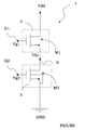
- the sole drawing shows a power amplifier according to the invention.
- a power amplifier according to the invention is globally and schematically indicated with 1.
- the power amplifier 1 comprises a load element 2 and an active element 3, inserted in series to each other between a first voltage reference, in particular the supply voltage Vdd, and a second voltage reference, in particular the ground GND.
- the load element 2 and the active element 3 are connected to each other to define a circuit node X which can also serve as additional output terminal of the power amplifier 1.
- the main output terminal is node Vdd.
- the load element 2 comprises a DMOS transistor M1 having a gate terminal G1 receiving a first control voltage Vg1.
- the active element 3 comprises a VLSI CMOS transistor M2 having a gate terminal G2 receiving a second control voltage Vg2.
- a high frequency bipolar transistor could also be used.
- the transistor M1 is sized and biased in order to optimise the cascode configuration performances of the power amplifier 1, the power consumption and the reliability.
- a value of the second control voltage Vg2 is set and the integration limits of the transistor M1 are fixed in order to allow the transistor M2 to work in saturation area.
- the power amplifier 1 has in fact a high cut off frequency as well as a high transconductance value. In the linear area a low activation resistance value is obtained.
- the transistor M2 working in saturation area, limits the peak voltage value in correspondence with the circuit node X to the gate-drain value that said transistor M2 can afford, i.e. Vx ⁇ ( Vg2 - V th2 ) being:
- a resistive element is connected between the drain and source terminals of the transistor M2 so as to ensure the right stabilisation of the circuit node X.
- the cascode configuration power amplifier 1 provides an area occupation depending on the sizing methodology applied.
- the optimisation of the knee current cascode amplifier can provide an area consumption corresponding to about 2-2.5 times an amplifier realised by means of a single DMOS transistor, with a corresponding increase in the output capacity being almost doubled.
- the cascoded power amplifier according to the invention has high cut off frequencies, high breakdown voltage values and high transconductance values in saturated area and low on-state resistance value, being therefore particularly suitable for radiofrequency applications.
Abstract
A power amplifier comprising at least a load element (2) and at least an
active element (3) inserted, in series to each other, between a first and a
second voltage reference (Vdd, GND) is described.
Advantageously, according to the invention, the load element (2)
comprises a DMOS transistor (Ml).
Description
- The present invention relates to a cascoded power amplifier, particularly for use in radiofrequency applications.
- More specifically, the invention relates to a power amplifier comprising at least a load element and at least an active element inserted, in series to each other, between a first and a second voltage reference.
- The invention relates particularly, but not exclusively, to a power amplifier for radiofrequency applications and the following description is made with reference to this field of application for convenience of illustration only.
- As it is well known, radiofrequency power amplifiers, or RF amplifiers, require high cut off frequencies as well as high breakdown voltage values in order to be able to provide high powers at high frequencies.
- Moreover, in order to obtain low feedback capacitance values, the use of devices with high transconductance values and low on-state resistance values is well known.
- Generally, some of these features are available in the VLSI CMOS BiCMOS and BCD standard silicon technologies. However, devices produced according to these technologies having all the above features simultaneously do not exist.
- In particular, LDMOS devices ensure high breakdown voltage values as well as high power values, but they have degraded radiofrequency performances.
- On the contrary, VLSI CMOS devices, particularly transistors with short gate length, have a high transconductance and a low high frequency on-stateresistance, but a low breakdown voltage value.
- The technical problem underlying the present invention is to provide a power amplifier, having such structural and functional characteristics so as to allow high cut off frequencies, high breakdown voltage value, high transconductance values and low on-state resistance values to be obtained, overcoming thus the limits still affecting at present the devices according to the prior art and allowing a right use thereof for radiofrequency applications.
- The solution idea underlying the present invention is to use a DMOS transistor and a CMOS transistor being conveniently connected in cascode configuration so as to obtain a power amplifier having optimum characteristics in radiofrequency applications.
- On the basis of this solution idea the technical problem is solved by a power amplifier as previously described and defined in the characterising part of
claim 1. - The features and advantages of the power amplifier according to the invention will be apparent from the following description of an embodiment thereof given by way of non-limiting example with reference to the attached drawing.
- The sole drawing shows a power amplifier according to the invention.
- With reference to the sole drawing, a power amplifier according to the invention is globally and schematically indicated with 1.
- The
power amplifier 1 comprises aload element 2 and anactive element 3, inserted in series to each other between a first voltage reference, in particular the supply voltage Vdd, and a second voltage reference, in particular the ground GND. - The
load element 2 and theactive element 3 are connected to each other to define a circuit node X which can also serve as additional output terminal of thepower amplifier 1. The main output terminal is node Vdd. - In the example shown in the figure, the
load element 2 comprises a DMOS transistor M1 having a gate terminal G1 receiving a first control voltage Vg1. - On the contrary, the
active element 3 comprises a VLSI CMOS transistor M2 having a gate terminal G2 receiving a second control voltage Vg2. A high frequency bipolar transistor could also be used. - Advantageously, according to the invention, once the integration limits of the transistor M2 are fixed, the transistor M1 is sized and biased in order to optimise the cascode configuration performances of the
power amplifier 1, the power consumption and the reliability. - In particular, a value of the second control voltage Vg2 is set and the integration limits of the transistor M1 are fixed in order to allow the transistor M2 to work in saturation area. In this way, the
power amplifier 1 has in fact a high cut off frequency as well as a high transconductance value. In the linear area a low activation resistance value is obtained. - It is worth noting that, advantageously, according to the invention, the transistor M2, working in saturation area, limits the peak voltage value in correspondence with the circuit node X to the gate-drain value that said transistor M2 can afford, i.e.
- Vx
- the voltage on the circuit node X;
- Vg2
- the voltage applied to the gate terminal G2 of the transistor M2; and
- Vth2
- the threshold voltage of the transistor M2.
- In an alternative embodiment, a resistive element is connected between the drain and source terminals of the transistor M2 so as to ensure the right stabilisation of the circuit node X.
- Direct current and alternating current simulations performed by the Applicant between an amplifier realised according to the invention by means of a DMOS transistor and a cascode configuration VLSI CMOS transistor and an amplifier realised according to the prior art by means of a CMOS transistor and a LDMOS transistor have shown the following performance improvements (to be considered only as indicative):
- cut off frequency increase by more than 185%;
- decrease by 50% in the product of the activation resistance and the CMOS channel length (Ron*W);
- early voltage (Vearly) huge increase by about 30 times;
- transconductance (gm*W) increase by 150%;
- feedback capacitance value (Cgd) decrease by 95%;
- breakdown voltage increase. The
power amplifier 1 failure is generally equal or higher than the transistor M 1 (load) failure and it is certainly higher than the transistor M2 (active element) failure. - Moreover it must be noticed that the cascode
configuration power amplifier 1 according to the invention provides an area occupation depending on the sizing methodology applied. For example, the optimisation of the knee current cascode amplifier can provide an area consumption corresponding to about 2-2.5 times an amplifier realised by means of a single DMOS transistor, with a corresponding increase in the output capacity being almost doubled. - In conclusion, the cascoded power amplifier according to the invention has high cut off frequencies, high breakdown voltage values and high transconductance values in saturated area and low on-state resistance value, being therefore particularly suitable for radiofrequency applications.
Claims (6)
- Power amplifier of the type comprising at least a load element (2) and at least an active element (3) inserted, in series to each other, between a first and a second voltage reference (Vdd, GND), characterised in that said load element (2) comprises a DMOS transistor (M1).
- Power amplifier according to claim 1, characterised in that said active element (3) comprises a VLSI CMOS transistor (M2).
- Power amplifier according to claim 1, characterised in that said active element (3) comprises a high frequency bipolar transistor.
- Power amplifier according to claim 2, characterised in that said DMOS transistor (M1) is sized and biased so that the VLSI CMOS transistor (M2) works in saturation area and complies with the relation.Vx a voltage value on a terminal (X) of said VLSI CMOS transistor (M2);Vg2 a voltage value on a control terminal (G2) of said VLSI CMOS transistor (M2); andVth2 a threshold voltage value of said VLSI CMOS transistor (M2).
- Power amplifier according to claim 1, characterised in that said load element (2) has a control terminal (G1) receiving a first control voltage (Vg1) being set so that the active element (3) works in saturation area.
- Power amplifier according to claim 1, characterised in that said active element (3) comprises a resistive element inserted between a circuit node (X) connecting said active element (3) to said load element (2) and said voltage reference (GND).
Priority Applications (2)
| Application Number | Priority Date | Filing Date | Title |
|---|---|---|---|
| EP02425729A EP1424771A1 (en) | 2002-11-28 | 2002-11-28 | Cascode power amplifier particularly for use in radiofrequency applications |
| US10/723,705 US7138875B2 (en) | 2002-11-28 | 2003-11-26 | Cascoded power amplifier, particularly for use in radio frequency |
Applications Claiming Priority (1)
| Application Number | Priority Date | Filing Date | Title |
|---|---|---|---|
| EP02425729A EP1424771A1 (en) | 2002-11-28 | 2002-11-28 | Cascode power amplifier particularly for use in radiofrequency applications |
Publications (1)
| Publication Number | Publication Date |
|---|---|
| EP1424771A1 true EP1424771A1 (en) | 2004-06-02 |
Family
ID=32241383
Family Applications (1)
| Application Number | Title | Priority Date | Filing Date |
|---|---|---|---|
| EP02425729A Withdrawn EP1424771A1 (en) | 2002-11-28 | 2002-11-28 | Cascode power amplifier particularly for use in radiofrequency applications |
Country Status (2)
| Country | Link |
|---|---|
| US (1) | US7138875B2 (en) |
| EP (1) | EP1424771A1 (en) |
Cited By (1)
| Publication number | Priority date | Publication date | Assignee | Title |
|---|---|---|---|---|
| US10608588B2 (en) | 2017-12-26 | 2020-03-31 | Nxp Usa, Inc. | Amplifiers and related integrated circuits |
Families Citing this family (3)
| Publication number | Priority date | Publication date | Assignee | Title |
|---|---|---|---|---|
| US8072270B2 (en) * | 2009-04-27 | 2011-12-06 | Broadcom Corporation | CMOS RF power amplifier with LDMOS bias circuit for large supply voltages |
| KR101101527B1 (en) * | 2010-03-29 | 2012-01-04 | 삼성전기주식회사 | Cmos power amplifier |
| US8482355B2 (en) | 2011-09-01 | 2013-07-09 | Samsung Electro-Mechanics Co., Ltd. | Power amplifier |
Citations (5)
| Publication number | Priority date | Publication date | Assignee | Title |
|---|---|---|---|---|
| EP0657995A1 (en) * | 1993-12-07 | 1995-06-14 | STMicroelectronics S.r.l. | Mixed typology output stage |
| US5463347A (en) * | 1994-12-12 | 1995-10-31 | Texas Instruments Incorporated | MOS uni-directional, differential voltage amplifier capable of amplifying signals having input common-mode voltage beneath voltage of lower supply and integrated circuit substrate |
| EP0790703A1 (en) * | 1996-02-14 | 1997-08-20 | Lucent Technologies Inc. | Quiescent current control for the output stage of an amplifier |
| US6353345B1 (en) * | 2000-04-04 | 2002-03-05 | Philips Electronics North America Corporation | Low cost half bridge driver integrated circuit with capability of using high threshold voltage DMOS |
| DE10114935A1 (en) * | 2001-03-20 | 2002-10-24 | Alpha Microelectronics Gmbh | Monolithically integrated high-voltage amplifier for capacitive actuators, has CMOS input amplifier, and layer for dielectrically insulating DMOS transistors in output stage from each other |
Family Cites Families (6)
| Publication number | Priority date | Publication date | Assignee | Title |
|---|---|---|---|---|
| US3449683A (en) * | 1967-04-26 | 1969-06-10 | Us Navy | Operational thin film amplifier |
| US4241316A (en) * | 1979-01-18 | 1980-12-23 | Lawrence Kavanau | Field effect transconductance amplifiers |
| US5508570A (en) * | 1993-01-27 | 1996-04-16 | Micro Linear Corporation | Differential amplifier based integrator having a left-half plane pole |
| US6002299A (en) * | 1997-06-10 | 1999-12-14 | Cirrus Logic, Inc. | High-order multipath operational amplifier with dynamic offset reduction, controlled saturation current limiting, and current feedback for enhanced conditional stability |
| US6346856B1 (en) * | 2000-05-16 | 2002-02-12 | Intersil Americas Inc. | Ultra linear high frequency transconductor structure |
| US6456159B1 (en) * | 2000-09-08 | 2002-09-24 | Analog Devices, Inc. | CMOS operational amplifier |
-
2002
- 2002-11-28 EP EP02425729A patent/EP1424771A1/en not_active Withdrawn
-
2003
- 2003-11-26 US US10/723,705 patent/US7138875B2/en not_active Expired - Lifetime
Patent Citations (5)
| Publication number | Priority date | Publication date | Assignee | Title |
|---|---|---|---|---|
| EP0657995A1 (en) * | 1993-12-07 | 1995-06-14 | STMicroelectronics S.r.l. | Mixed typology output stage |
| US5463347A (en) * | 1994-12-12 | 1995-10-31 | Texas Instruments Incorporated | MOS uni-directional, differential voltage amplifier capable of amplifying signals having input common-mode voltage beneath voltage of lower supply and integrated circuit substrate |
| EP0790703A1 (en) * | 1996-02-14 | 1997-08-20 | Lucent Technologies Inc. | Quiescent current control for the output stage of an amplifier |
| US6353345B1 (en) * | 2000-04-04 | 2002-03-05 | Philips Electronics North America Corporation | Low cost half bridge driver integrated circuit with capability of using high threshold voltage DMOS |
| DE10114935A1 (en) * | 2001-03-20 | 2002-10-24 | Alpha Microelectronics Gmbh | Monolithically integrated high-voltage amplifier for capacitive actuators, has CMOS input amplifier, and layer for dielectrically insulating DMOS transistors in output stage from each other |
Non-Patent Citations (1)
| Title |
|---|
| HONG M Y: "SIMULATION AND FABRICATION OF SUBMICRON CHANNEL LENGTH DMOS TRANSISTORS FOR ANALOG APPLICATIONS", IEEE TRANSACTIONS ON ELECTRON DEVICES, IEEE INC. NEW YORK, US, VOL. 40, NR. 12, PAGE(S) 2222-2230, ISSN: 0018-9383, XP000541407 * |
Cited By (1)
| Publication number | Priority date | Publication date | Assignee | Title |
|---|---|---|---|---|
| US10608588B2 (en) | 2017-12-26 | 2020-03-31 | Nxp Usa, Inc. | Amplifiers and related integrated circuits |
Also Published As
| Publication number | Publication date |
|---|---|
| US7138875B2 (en) | 2006-11-21 |
| US20040104777A1 (en) | 2004-06-03 |
Similar Documents
| Publication | Publication Date | Title |
|---|---|---|
| US4342967A (en) | High voltage, high frequency amplifier | |
| US8648656B2 (en) | Low-noise amplifier with through-mode | |
| US7279980B2 (en) | Non-uniform distributed multi-stage circuits | |
| KR102256958B1 (en) | Amplification circuit | |
| JP2004515937A (en) | Cascode bootstrap analog power amplifier circuit | |
| US8138839B2 (en) | Wideband CMOS gain stage | |
| US7847638B2 (en) | Cascoded circuit | |
| US7348855B2 (en) | Bias circuitry for cascode transistor circuit | |
| US20230283247A1 (en) | Device Stack with Novel Gate Capacitor Topology | |
| US7728671B2 (en) | Semiconductor power device with bias circuit | |
| EP0429268A2 (en) | Current-mirror circuit with buffering transistor | |
| US4612514A (en) | Feedback amplifier | |
| US8022764B2 (en) | Differential amplifier | |
| EP1424771A1 (en) | Cascode power amplifier particularly for use in radiofrequency applications | |
| US20060183449A1 (en) | Gain variable voltage/current conversion circuit and filter circuit using the same | |
| JP2000036564A (en) | Variable resistor and gain circuit | |
| JP4255703B2 (en) | Cascode power amplifier | |
| US7205837B2 (en) | Body effect amplifier | |
| JP4750710B2 (en) | MMIC distributed amplifier gate control using active bias | |
| KR950024415A (en) | High frequency amplification method using MOS F element | |
| US6784742B2 (en) | Voltage amplifying circuit | |
| US6489827B1 (en) | Reduction of offset voltage in current mirror circuit | |
| KR101591689B1 (en) | Semiconductor device | |
| US6043713A (en) | Amplifier with temperature compensation function | |
| KR101516327B1 (en) | Apparatus and method for analog integrated circuit |
Legal Events
| Date | Code | Title | Description |
|---|---|---|---|
| PUAI | Public reference made under article 153(3) epc to a published international application that has entered the european phase |
Free format text: ORIGINAL CODE: 0009012 |
|
| AK | Designated contracting states |
Kind code of ref document: A1 Designated state(s): AT BE BG CH CY CZ DE DK EE ES FI FR GB GR IE IT LI LU MC NL PT SE SK TR |
|
| AX | Request for extension of the european patent |
Extension state: AL LT LV MK RO SI |
|
| 17P | Request for examination filed |
Effective date: 20041130 |
|
| AKX | Designation fees paid |
Designated state(s): DE FR GB IT |
|
| 17Q | First examination report despatched |
Effective date: 20070530 |
|
| STAA | Information on the status of an ep patent application or granted ep patent |
Free format text: STATUS: THE APPLICATION IS DEEMED TO BE WITHDRAWN |
|
| 18D | Application deemed to be withdrawn |
Effective date: 20080603 |