EP1424568A2 - Dètecteur de particules et dispositif de comptage comprenant un pluralité de détecteurs de particules - Google Patents
Dètecteur de particules et dispositif de comptage comprenant un pluralité de détecteurs de particules Download PDFInfo
- Publication number
- EP1424568A2 EP1424568A2 EP03104362A EP03104362A EP1424568A2 EP 1424568 A2 EP1424568 A2 EP 1424568A2 EP 03104362 A EP03104362 A EP 03104362A EP 03104362 A EP03104362 A EP 03104362A EP 1424568 A2 EP1424568 A2 EP 1424568A2
- Authority
- EP
- European Patent Office
- Prior art keywords
- particle
- detector
- detectors
- particle detector
- counting
- Prior art date
- Legal status (The legal status is an assumption and is not a legal conclusion. Google has not performed a legal analysis and makes no representation as to the accuracy of the status listed.)
- Granted
Links
Images



Classifications
-
- G—PHYSICS
- G01—MEASURING; TESTING
- G01T—MEASUREMENT OF NUCLEAR OR X-RADIATION
- G01T1/00—Measuring X-radiation, gamma radiation, corpuscular radiation, or cosmic radiation
- G01T1/16—Measuring radiation intensity
- G01T1/24—Measuring radiation intensity with semiconductor detectors
- G01T1/247—Detector read-out circuitry
-
- G—PHYSICS
- G01—MEASURING; TESTING
- G01T—MEASUREMENT OF NUCLEAR OR X-RADIATION
- G01T1/00—Measuring X-radiation, gamma radiation, corpuscular radiation, or cosmic radiation
- G01T1/29—Measurement performed on radiation beams, e.g. position or section of the beam; Measurement of spatial distribution of radiation
-
- G—PHYSICS
- G01—MEASURING; TESTING
- G01T—MEASUREMENT OF NUCLEAR OR X-RADIATION
- G01T1/00—Measuring X-radiation, gamma radiation, corpuscular radiation, or cosmic radiation
- G01T1/29—Measurement performed on radiation beams, e.g. position or section of the beam; Measurement of spatial distribution of radiation
- G01T1/2914—Measurement of spatial distribution of radiation
- G01T1/2921—Static instruments for imaging the distribution of radioactivity in one or two dimensions; Radio-isotope cameras
- G01T1/2928—Static instruments for imaging the distribution of radioactivity in one or two dimensions; Radio-isotope cameras using solid state detectors
-
- H—ELECTRICITY
- H04—ELECTRIC COMMUNICATION TECHNIQUE
- H04N—PICTORIAL COMMUNICATION, e.g. TELEVISION
- H04N25/00—Circuitry of solid-state image sensors [SSIS]; Control thereof
- H04N25/70—SSIS architectures; Circuits associated therewith
- H04N25/76—Addressed sensors, e.g. MOS or CMOS sensors
- H04N25/77—Pixel circuitry, e.g. memories, A/D converters, pixel amplifiers, shared circuits or shared components
- H04N25/772—Pixel circuitry, e.g. memories, A/D converters, pixel amplifiers, shared circuits or shared components comprising A/D, V/T, V/F, I/T or I/F converters
- H04N25/773—Pixel circuitry, e.g. memories, A/D converters, pixel amplifiers, shared circuits or shared components comprising A/D, V/T, V/F, I/T or I/F converters comprising photon counting circuits, e.g. single photon detection [SPD] or single photon avalanche diodes [SPAD]
Definitions
- the invention relates to a particle detector comprising counting means for delivering a count information relating to a number of detected particles as well as a counting device of particles comprising a plurality of particles.
- the invention also relates to a method of particle detector reading and a method particle detector matrix reading.
- the invention applies, inter alia, to the field of radiology (radiography, radioscopy).
- the detected particles are then X-rays.
- the training devices images used in radiology consist of detector matrices.
- Each detector plus commonly called “detector pixel”, delivers a signal that is a function of the amount of particles that it detects.
- X-ray is a high-resolution exam space on a single image made on the basis a medium or high dose of irradiation.
- the detector must have small detector pixels (typically from 50pm to 150 ⁇ m).
- Fluoroscopy is a video rhythm exam that can last from several seconds to several minutes.
- the irradiation dose per image is then much more low so that the cumulative total dose by a patient be acceptable.
- We then obtain a noisy image because the statistics of the number of photons detected by Pixel detector is bad. It is then illusory to want to detect objects the size of pixels.
- X-ray and fluoroscopy therefore have very different modes of operation. It is known, however, to implement these two operating modes using matrixes of detectors working by integrating currents of detection in storage capacities.
- Detector pixels are grouped, usually by four (2x2) or sixteen (4x4), before being played. Thus, without losing in spatial resolution, we reduce the output rate. This also reduces the reading noise. Detector pixel clusters are made by mixing the information of the storage capacities of the pixels concerned, before reading, by turning on switches which link. Then just read any of the detector pixels of the group to obtain the average of detected information.
- the invention does not have the disadvantages mentioned above.
- the invention relates to a detector of particles comprising means for delivering electrical impulses from particles detected, an electrical pulse delivered corresponding to a detected particle, and means counting electrical pulses delivered.
- the detector comprises means capable of receiving and transmit to the counting means impulses from at least one second detector of particles and means capable of transmitting the electrical impulses that it delivers and impulses electrical signals it receives from said second detector of particles to means of counting a third particle detector.
- the means capable of receiving and to be transmitted to the pulse counting means from at least one second detector of particles and the means capable of transmitting electrical impulses that it delivers and impulses electrical signals it receives from said second detector of particles to means of counting a third particle detector include an "OR" door having a first entry on which are applied the electrical pulses delivered by the detector of particles, at least one additional entry on which are applied the electrical impulses delivered by the second particle detector, and an output connected, on the one hand, to an input of the means counting and, on the other hand, to an entrance to a door "OR" counting means of the third detector of particles.
- the particle detector includes a monostable device placed between the output means to deliver electrical pulses from the detected particles and the first entry.
- the particle detector is such that means capable of receiving and transmitting to the means counting electrical pulses from minus a second particle detector and the means able to transmit the electrical impulses he delivers and the electrical impulses he receives said second particle detector to means counting a third particle detector include a switch mounted in series on the input additional.
- the particle detector comprises means of inhibiting the functioning of counting means.
- the invention also relates to a device for particle counting comprising a plurality of particle detectors according to the invention.
- the particle detectors of the counting device are arranged as an array of detectors.
- the counting device comprises means for arranging the particle detectors under the shape of N blocks of n x m particle detectors neighbors, N, n and m being higher whole numbers or equal to 1, so that at least one block of particle detectors includes a detector of particles that count the particles detected by any or part of the particle detectors of the block.
- the counting device comprises means for modifying the number n x m of detectors of particles that participate in at least one block of particle detectors.
- a particle detector Di / j located at the intersection of a line of rank i and a column of rank j includes an "OR" gate with three inputs, a first additional input being connected to a first switch and a second input additional being connected to a second switch, the first and second switches of the detector of particles Di / j being respectively connected to the exit from the "OR" gate of the particle detector D (i-1) / j and at the exit of the "OR” gate of the detector particles Di / (j-1), the output of the "OR” gate of detector Di / j being connected to the first switch of the particle detector D (i + 1) / d and at the second switch of the particle detector Di / (j + 1).
- the invention also relates to a method of particle detector reading.
- the process comprises a step during which at least one first detector of particles receives and counts the pulses delivered by at least a second particle detector and a stage during which the impulses delivered by the first particle detector and pulses delivered to the first particle detector by the second particle detector are transmitted to counting means of a third detector of particles.
- the invention also relates to a method of counting of particles detected by a matrix of particle detectors.
- the method comprises a step of control for arranging particle detectors of the matrix in the form of N blocks of n x m neighboring particle detectors, N, n and m being integers greater than or equal to 1, the detectors of particles of at least one block being read using a detector reading method according to the invention of so that a particle detector of said at least one block counts the particles detected by all or part n x m particle detectors of said block.
- the counting method includes an inhibition of the means counting particle detectors of the block others that the particle detector of the block that counts the particles detected by all or part of the m x n particle detectors.
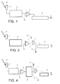
- FIG. 1 represents a detector of particles according to the prior art including means of counting to deliver counting information relating to a number of detected particles.
- the particle detector includes an element semiconductor 1, a processing circuit 2, a comparator 3 and a counter 4.
- the semiconductor element 1 includes one or more layers of detection that absorb particles P, for example X-rays, and transform them into pulses electric.
- Processing circuit 2 processes the electrical impulses (amplification, filtering, etc.) and comparator 3 compares each electrical pulse from the processing circuit 2 to a threshold voltage Vs. comparator 3 thus delivers a pulse digital electric from the electrical pulse from the processing circuit 2.
- the pulses digital meters increment the counter 4. At the end of the irradiation, the counter 4 contains a information representative of the number N of particles detected.
- FIG. 2 represents a counting device of particles comprising a plurality of particles according to the known art.
- the counting device is arranged in the form of rows and columns of detectors.
- An address shift register 5 of lines order, line by line, reading counters 4.
- the count information issued by a counter 4 are transmitted, column by column, to a column multiplexer 6.
- Figure 3 represents a first example of particle detector comprising means for counting according to the invention.
- the particle detector according to the invention comprises an "OR” gate 7 placed between the comparator 3 and the counter 4.
- the "OR” gate has a first input connected to the output of comparator 3 and a second input connected to the exit of a door “OR” of a first neighbor detector (not shown on the face).
- the exit of the "OR” door is connected, on the one hand, to meter 4 and, on the other an entry of an "OR” door of a second detector neighbor (also not shown in the figure).
- the "OR” gate 7 performs the "OR” function between the digital pulse I delivered by the comparator 3 and a digital pulse the delivered by the comparator of the first neighboring detector.
- each detector performs the "OR” function between pulses that it detects and impulses in from a nearby detector. Each detector can so count his own events as well as the events that matter.
- the duration of the pulse delivered by the semiconductor element 1 is very short, for example 10ns, it may be that the treatment device 2 very substantially elongates this duration to carry this one, for example, up to 100 ns.
- the comparator can then switch to 1 during all this duration.
- the "OR" door is then insensitive to information imported from the neighboring detector during all this duration.
- Figure 4 shows a improvement of the circuit of FIG. to reduce the duration of the pulse at the output of 3.
- a monostable device 8 is then interposed between the output of the comparator 3 and the input of the "OR” door 7.
- the monostable device 8 triggers on the rising edges of the output of the comparator and automatically returns to zero after a predetermined time, for example 5 ns.
- the impulses processed by the "OR” door are then brief and advantageously allow a high counting rate.
- a particle detector according to the invention comprises such a device.
- Figure 5 shows a first example of counting device comprising a plurality of particle detectors according to the invention.
- the counting device represented, as a example, in Figure 5, includes a group of four particle detectors D1 / 1, D1 / 2, D2 / 1, D2 / 2 arranged on two lines and two columns.
- the "OR" gates 9 of the D1 / 1 detectors, D1 / 2, D2 / 1, and D2 / 2 include three entries for collect detected pulses. If he's necessary that the "OR" gate of the D2 / 2 detector includes three entries to collect the different pulses detected, it is clear that two inputs are sufficient for the "OR” gate of the D2 / 1 detector and that only one entry is sufficient for the "OR” doors of detectors D1 / 1 and D1 / 2. It is for reasons of convenience (making identical circuits) that the "OR" doors of all detectors have three entries.
- each detector can then comprise means for inhibit the counter it contains.
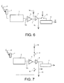
- An equipped detector means for inhibiting the counter is represented by example, in Figure 6.
- the means for inhibiting the counter 4 consist of a controlled C switch to open when the counter must be inhibited and close when the counter must be active.
- the particle detector includes means for to change the number of detectors that participate in a group of detectors.
- Figure 7 shows a example of particle detector according to such development.
- a first entry of the door "OR” 9 to three inputs is connected to a first switch A and a second entry of the "OR” gate 9 is connected to a second switch B.
- the same particle detector is used individually (X-ray mode), in a group of 2x2 detectors (first example of mode radioscopy) or in a group of 4x4 detectors (second example of a fluoroscopy mode), others groups of detectors being also possible.
- opening a switch A or B is not enough to control properly the entry state of the "OR” door 9.
- the entry of the door "OR” 9 which is connected to a switch in open position must then be brought to a level logic "0" (case of positive logic) to ensure correct operation of the detector.
- FIG. 8 represents, by way of example, a counting device according to the invention a matrix of sixteen detectors (4x4) such as the detector shown in Figure 7.
- circuits capable of carrying the entrances of "OR" gates at logic level "0" (case of positive logic) when the switches A, B are in the open position were not represented on the Fig.
- the first and second switches A and B of a detector Di / j are respectively connected to the exit from the "OR" gate of the detector D (i-1) / j and to the exit from the "OR” gate of the detector Di / (j-1) .By elsewhere, the output of the "OR" gate of a detector Di / j is connected to the first switch A of the detector D (i + 1) / j and the second switch B of the detector Di / (j + 1).
- Switches A and B are connected to different commands k1, k2, k3.
- commands k1, k2, k3 As an example limiting, a particular embodiment relating to The commands k1, k2, k3 will now be described.
- the k1 command blocks switches on which it is applied.
- the orders k2 and k3 will now be specified according to cases.
- each detector is used individually (X-ray mode)
- the commands k2 and k3 are then brought to the low level (in positive logic). All switches are then blocked. Each detector does not only the particles it detects.
- the detectors are used in groups of 2x2 adjacent detectors (first example of radioscopy mode)
- the k2 and k4 commands are brought to the level high (case of positive logic).
- a wide variety of geometries of groups of detecting pixels are advantageously possible according to the invention. It is thus possible, for example, to group the pixels detectors according to only one direction (line or column).
- the groupings of n lines x 1 column can be interesting. Indeed, these groupings only require "OR" functions to two entries, remove horizontal links between detector pixels, make it possible to accelerate the reading of the array of detectors since only one line on n is addressed, and move the problem of summation of columns on the periphery or outside of the matrix, which in some cases may be acceptable in view of the previous benefits.
- an isolated detector pixel may be defective. Missing information from defective sensor pixel is then replaced by the average value of the signals detected by the neighboring pixels of the pixel defective. This average value is calculated by a image processing system.
- group of detector pixels it is not acceptable only one defective pixel can cause the loss information contained in a whole group of pixels detectors. The counting device according to the invention avoids this inconvenience, as it goes appear on reading the example described below.
- Reading the detector D8 / 8 is done by addressing the eighth line and selecting the eighth column. Suppose the detector D8 / 8 is defective (such information can be obtained, for example, during a reading individual detectors). Instead of reading the detectors D8 / 4, D8 / 8, D8 / 12 and D8 / 16 that deliver the information contained in the groups of detectors of lines of rank 5, 6, 7, 8, it is then detectors D8 / 4, D8 / 7, D8 / 12 and D8 / 16 which are read.
- the detector D8 / 7 contains the sum of the signals nine detectors of the group out of sixteen. The block of detectors is therefore always represented in the image formed, despite a lower signal-to-noise ratio than in nominal groups.
Landscapes
- Physics & Mathematics (AREA)
- Health & Medical Sciences (AREA)
- Life Sciences & Earth Sciences (AREA)
- General Physics & Mathematics (AREA)
- High Energy & Nuclear Physics (AREA)
- Molecular Biology (AREA)
- Spectroscopy & Molecular Physics (AREA)
- Engineering & Computer Science (AREA)
- Multimedia (AREA)
- Signal Processing (AREA)
- Measurement Of Radiation (AREA)
- Analysing Materials By The Use Of Radiation (AREA)
Abstract
Description
- la figure 1 représente un détecteur de particules comprenant des moyens de comptage pour délivrer une information de comptage relative à un nombre de particules détectées selon l'art connu ;
- la figure 2 représente un dispositif de comptage de particules comprenant une pluralité de détecteurs de particules selon l'art connu ;
- la figure 3 représente un premier exemple de détecteur de particules comprenant des moyens de comptage selon l'invention ;
- la figure 4 représente un premier perfectionnement du détecteur de particules selon l'invention ;
- la figure 5 représente un premier exemple de dispositif de comptage comprenant une pluralité de détecteurs de particules selon l'invention ;
- la figure 6 représente un deuxième perfectionnement du détecteur de particules selon l'invention ;
- la figure 7 représente un deuxième exemple de détecteur de particules comprenant des moyens de comptage selon l'invention ;
- la figure 8 représente un exemple de dispositif de comptage comprenant une pluralité de détecteurs de particules selon le deuxième exemple de l'invention ;
- la figure 9 représente, de façon symbolique, un exemple de matrice de détecteurs de particules formant dispositif de comptage selon l'invention.
- le compteur du détecteur D1/1 compte les particules détectées par le détecteur D1/1 ;
- le compteur du détecteur D2/1 compte les particules détectées par les détecteurs D2/1 et D1/1 ;
- le compteur du détecteur D1/2 compte les particules détectées par le détecteur D1/2 ; et
- le compteur du détecteur D2/2 compte les particules détectées par les quatre détecteurs D1/1, D1/2, D2/1 et D2/2.
- sur les interrupteurs A et B des détecteurs de la première ligne,
- sur les interrupteurs B des détecteurs D2/1 et D2/3,
- sur les interrupteurs A des détecteurs D3/1 et D3/3 et de l'ensemble des interrupteurs B des détecteurs de la troisième ligne,
- sur l'interrupteur B du détecteur D4/1.
- sur l'ensemble des interrupteurs A des détecteurs de la deuxième ligne et sur les interrupteurs B des détecteurs D2/2 et D2/4,
- sur l'ensemble des interrupteurs A des détecteurs de la quatrième ligne et sur les interrupteurs B des détecteurs D4/2 et D4/4.
- le détecteur D2/2 compte les particules des détecteurs D1/1, D1/2, D2/1, et D2/2,
- le détecteur D2/4 compte les particules des détecteurs D1/3, D1/4, D2/3 et D2/4,
- le détecteur D4/2 compte les particules des détecteurs D3/1, D3/2, D4/1, et D4/2,
- le détecteur D4/4 compte les particules des détecteurs D3/3, D3/4,D4/3 et D4/4.
- image n°1 : position de référence de chaque groupe (c'est la position de départ pour chaque groupe) ;
- image n°2 : décalage de la position d'un groupe de +2 lignes en horizontal, sans décalage vertical ;
- image n°3 : décalage de la position d'un groupe de +2 lignes en horizontal et de +2 colonnes en vertical ;
- image n°4 : décalage de la position d'un groupe de +2 colonnes en vertical, sans décalage en horizontal ;
- image n°5 : retour à la position de référence des groupes ; etc.
- les détecteurs D4/4, D4/8, D4/12, et D4/16 pour les lignes de rang 1, 2, 3, 4,
- les détecteurs D8/4, D8/8, D8/8 et D8/16 pour les lignes de rang 5, 6, 7, 8, et
- les détecteurs D12/4, D12/8, D12/12 et D12/16 pour les lignes de rang 9, 10, 11, 12.
Claims (13)
- Détecteur de particules comprenant des moyens (1, 2, 3) pour délivrer des impulsions électriques à partir de particules détectées, une impulsion électrique délivrée correspondant à une particule détectée, et des moyens de comptage (4) des impulsions électriques délivrées, caractérisé en ce qu'il comprend des moyens aptes à recevoir et à transmettre aux moyens de comptage (4) des impulsions électriques provenant d'au moins un deuxième détecteur de particules et des moyens aptes à transmettre les impulsions électriques qu'il délivre et les impulsions électriques qu'il reçoit dudit deuxième détecteur de particules vers des moyens de comptage d'un troisième détecteur de particules.
- Détecteur de particules selon la revendication 1, dans lequel les moyens aptes à recevoir et à transmettre aux moyens de comptage (4) des impulsions électriques provenant d'au moins un deuxième détecteur de particules et les moyens aptes à transmettre les impulsions électriques qu'il délivre et les impulsions électriques qu'il reçoit dudit deuxième détecteur de particules vers un troisième détecteur de particules comprennent une porte « OU » ayant une première entrée sur laquelle sont appliquées les impulsions électriques délivrées par le détecteur de particules, au moins une entrée supplémentaire sur laquelle sont appliquées les impulsions électriques délivrées par le deuxième détecteur de particules, et une sortie reliée, d'une part, à une entrée des moyens de comptage (4) et, d'autre part, à une entrée d'une porte « OU » des moyens de comptage du troisième détecteur de particules.
- Détecteur de particules selon la revendication 2, dans lequel un dispositif monostable est placé entre la sortie des moyens (1, 2, 3) pour délivrer des impulsions électriques à partir des particules détectées et la première entrée.
- Détecteur de particules selon l'une quelconque des revendications 2 ou 3, caractérisé en ce que les moyens aptes à recevoir et à transmettre aux moyens de comptage (4) des impulsions électriques provenant d'au moins un deuxième détecteur de particules et les moyens aptes à transmettre les impulsions électriques qu'il délivre et les impulsions électriques qu'il reçoit dudit deuxième détecteur de particules vers des moyens de comptage d'un troisième détecteur de particules comprennent un interrupteur (A, B) monté en série sur l'entrée supplémentaire.
- Détecteur de particules selon l'une quelconque des revendications précédentes, caractérisé en ce qu'il comprend des moyens (C) permettant d'inhiber le fonctionnement des moyens de comptage (4).
- Dispositif de comptage de particules, caractérisé en ce qu'il comprend une pluralité de détecteurs de particules selon l'une quelconque des revendications 1 à 5.
- Dispositif de comptage selon la revendication 6, caractérisé en ce que les détecteurs de particules sont agencés sous forme de matrice de détecteurs.
- Dispositif de comptage selon la revendication 7, caractérisé en ce qu'il comprend des moyens pour agencer les détecteurs de particules sous la forme de N blocs de n x m détecteurs de particules voisins, N, n et m étant des nombres entiers supérieurs ou égaux à 1, de sorte qu'au moins un bloc de détecteurs de particules comprenne un détecteur de particules qui compte les particules détectées par tout ou partie des détecteurs de particules du bloc.
- Dispositif de comptage selon la revendication 8, caractérisé en ce qu'il comprend des moyens pour modifier le nombre de détecteurs de particules qui participent à au moins un bloc de détecteurs de particules.
- Dispositif de comptage selon l'une quelconque des revendications 7 à 9, caractérisé en ce qu'un détecteur de particules Di/j situé à l'intersection d'une ligne de rang i et d'une colonne de rang j, comprend une porte « OU » à trois entrées, une première entrée supplémentaire étant reliée à un premier interrupteur (A) et une deuxième entrée supplémentaire étant reliée à un deuxième interrupteur (B), les premier (A) et deuxième (B) interrupteurs du détecteur de particules Di/j étant reliés, respectivement, à la sortie de la porte « OU » du détecteur de particules D(i-1)/j et à la sortie de la porte « OU » du détecteur de particules Di/(j-1), la sortie de la porte « OU » du détecteur Di/j étant reliée au premier interrupteur (A) du détecteur de particules D(i+1)/j et au deuxième interrupteur (B) du détecteur de particules Di/(j+1).
- Procédé de lecture de détecteur de particules, caractérisé en ce qu'il comprend une étape durant laquelle au moins un premier détecteur de particules reçoit et compte les impulsions délivrées par au moins un deuxième détecteur de particules et une étape de durant laquelle les impulsions délivrées par le premier détecteur de particules et les impulsions délivrées au premier détecteur de particules par le deuxième détecteur de particules sont transmises vers des moyens de comptage d'un troisième détecteur de particules.
- Procédé de comptage de particules détectées par une matrice de détecteurs de particules, caractérisé en ce qu'il comprend une étape de commande pour agencer les détecteurs de particules de la matrice sous la forme de N blocs de n x m détecteurs de particules voisins, N, n et m étant des entiers supérieurs ou égaux à 1, les détecteurs de particules d'au moins un bloc étant lues à l'aide d'un procédé de lecture selon la revendication 11 de sorte qu'un détecteur de particules dudit au moins un bloc compte les particules détectées par tout ou partie des n x m détecteurs de particules dudit bloc.
- Procédé selon la revendication 12, caractérisé en ce qu'il comprend une inhibition de moyens de comptage des détecteurs de particules du bloc autres que le détecteur de particules du bloc qui compte les particules détectées par tout ou partie des m x n détecteurs de particules.
Applications Claiming Priority (2)
| Application Number | Priority Date | Filing Date | Title |
|---|---|---|---|
| FR0214811 | 2002-11-26 | ||
| FR0214811A FR2847677B1 (fr) | 2002-11-26 | 2002-11-26 | Detecteur de particules et dispositif de comptage comprenant une pluralite de detecteurs de particules |
Publications (3)
| Publication Number | Publication Date |
|---|---|
| EP1424568A2 true EP1424568A2 (fr) | 2004-06-02 |
| EP1424568A3 EP1424568A3 (fr) | 2004-07-07 |
| EP1424568B1 EP1424568B1 (fr) | 2015-11-18 |
Family
ID=32241618
Family Applications (1)
| Application Number | Title | Priority Date | Filing Date |
|---|---|---|---|
| EP03104362.3A Expired - Lifetime EP1424568B1 (fr) | 2002-11-26 | 2003-11-25 | Dètecteur de particules et dispositif de comptage comprenant un pluralité de détecteurs de particules |
Country Status (3)
| Country | Link |
|---|---|
| US (1) | US7057179B2 (fr) |
| EP (1) | EP1424568B1 (fr) |
| FR (1) | FR2847677B1 (fr) |
Cited By (1)
| Publication number | Priority date | Publication date | Assignee | Title |
|---|---|---|---|---|
| FR2877733A1 (fr) * | 2004-11-05 | 2006-05-12 | Commissariat Energie Atomique | Circuit de detection de particules avec des circuits elementaires constituant des sous-pixels |
Families Citing this family (7)
| Publication number | Priority date | Publication date | Assignee | Title |
|---|---|---|---|---|
| FR2864731B1 (fr) * | 2003-12-30 | 2006-02-03 | Commissariat Energie Atomique | Systeme de detection de rayonnements permettant un meilleur comptage d'evenements |
| JP4825443B2 (ja) * | 2004-05-11 | 2011-11-30 | 株式会社東芝 | X線ct装置、放射線検出器および放射線検出器における電気信号の読出方法 |
| US9008378B2 (en) | 2006-12-20 | 2015-04-14 | The Board Of Trustees Of The Leland Stanford Junior University | Arrangement and imaging of biological samples |
| JP2010287215A (ja) * | 2009-05-11 | 2010-12-24 | Ricoh Co Ltd | 情報入力装置、画像形成装置、入力制御方法、及び入力制御プログラムを記録した記録媒体 |
| WO2011089528A2 (fr) * | 2010-01-22 | 2011-07-28 | DenCT Ltd | Procédés et appareil pour détecteur de rayons x à écran plat à caméras multiples |
| KR101871361B1 (ko) | 2011-11-01 | 2018-08-03 | 삼성전자주식회사 | 고해상도 및 고대조도 영상을 동시에 생성하기 위한 광자 계수 검출 장치 및 방법 |
| DE102015213911B4 (de) * | 2015-07-23 | 2019-03-07 | Siemens Healthcare Gmbh | Verfahren zum Erzeugen eines Röntgenbildes und Datenverarbeitungseinrichtung zum Ausführen des Verfahrens |
Family Cites Families (7)
| Publication number | Priority date | Publication date | Assignee | Title |
|---|---|---|---|---|
| US5066861A (en) * | 1987-07-22 | 1991-11-19 | Kanegafuchi Chemical Industry Co., Ltd. | X ray detecting device |
| US5107122A (en) * | 1990-10-12 | 1992-04-21 | Hughes Aircraft Company | Sparse readout method and apparatus for a pixel array |
| US5970115A (en) * | 1996-11-29 | 1999-10-19 | Varian Medical Systems, Inc. | Multiple mode digital X-ray imaging system |
| JPH10285466A (ja) * | 1997-04-07 | 1998-10-23 | Toshiba Corp | 撮像装置 |
| EP1102323B1 (fr) * | 1999-11-19 | 2012-08-15 | CSEM Centre Suisse d'Electronique et de Microtechnique SA - Recherche et Développement | Procédé de détection de rayonnement électromagnétique utilisant un capteur opto-électronique |
| US6420712B1 (en) * | 2000-07-03 | 2002-07-16 | The Regents Of The University Of California | Cosmic ray neutron background reduction using localized coincidence veto neutron counting |
| FR2847678B1 (fr) * | 2002-11-27 | 2005-01-07 | Commissariat Energie Atomique | Detecteur de particules et procede de detection de particules associe |
-
2002
- 2002-11-26 FR FR0214811A patent/FR2847677B1/fr not_active Expired - Fee Related
-
2003
- 2003-11-19 US US10/716,692 patent/US7057179B2/en not_active Expired - Fee Related
- 2003-11-25 EP EP03104362.3A patent/EP1424568B1/fr not_active Expired - Lifetime
Cited By (3)
| Publication number | Priority date | Publication date | Assignee | Title |
|---|---|---|---|---|
| FR2877733A1 (fr) * | 2004-11-05 | 2006-05-12 | Commissariat Energie Atomique | Circuit de detection de particules avec des circuits elementaires constituant des sous-pixels |
| WO2006051179A1 (fr) * | 2004-11-05 | 2006-05-18 | Commissariat à l'Energie Atomique | Circuit de détection de particules avec des circuits élémentaires constituant des sous-pixels |
| US7652260B2 (en) | 2004-11-05 | 2010-01-26 | Commissariat A L'energie Atomique | Particle detection circuit comprising basic circuits forming subpixels |
Also Published As
| Publication number | Publication date |
|---|---|
| EP1424568B1 (fr) | 2015-11-18 |
| FR2847677A1 (fr) | 2004-05-28 |
| FR2847677B1 (fr) | 2005-01-07 |
| US7057179B2 (en) | 2006-06-06 |
| US20040144926A1 (en) | 2004-07-29 |
| EP1424568A3 (fr) | 2004-07-07 |
Similar Documents
| Publication | Publication Date | Title |
|---|---|---|
| EP1959673B1 (fr) | Detecteur de rayonnement X ou gamma | |
| EP3721616B1 (fr) | Capteur d'image haute dynamique | |
| EP2567540B1 (fr) | Capteur d'image lineaire a defilement et sommation analogique et numerique et procede correspondant | |
| EP1550884B1 (fr) | Système de détection de rayonnements comportant une pluralité d'éléments détecteurs ayant chacun un circuit d'acquisition et de comptage | |
| EP2064867B1 (fr) | Capteur d'image en defilement par integrations successives et sommation, a pixels cmos actifs | |
| EP2846533B1 (fr) | Dispositif d'acquisition compressive d'une image | |
| EP2774355B1 (fr) | Capteur d'image a defilement et sommation numerique multiphase | |
| EP1424568B1 (fr) | Dètecteur de particules et dispositif de comptage comprenant un pluralité de détecteurs de particules | |
| FR2973162A1 (fr) | Capteur d'image a tres haute dynamique | |
| EP2846535A1 (fr) | Dispositif et procédé d'acquisition compressive d'images | |
| EP3386186B1 (fr) | Capteur d'images | |
| WO2008034677A1 (fr) | Capteur d'image lineaire cmos a fonctionnement de type transfert de charges | |
| FR2866178A1 (fr) | Procede et dispositif pour ameliorer l'acquisition de donnees a l'aide d'un detecteur numeriques de rayons x | |
| EP3386191B1 (fr) | Capteur matriciel a codage temporel sans arbitrage | |
| EP1869499B1 (fr) | Circuit de détection de particules avec des circuits élémentaires constituant des sous-pixels | |
| EP3026890B1 (fr) | Contrôle de la durée d'intégration dans un dispositif photosensible | |
| FR2977371A1 (fr) | Matrice de pixels a groupements programmables | |
| FR2847678A1 (fr) | Detecteur de particules et procede de detection de particules associe | |
| WO2014195622A1 (fr) | Capteur CMOS à photosites standard | |
| EP4066483A1 (fr) | Saisie d'images utilisant des éléments sensibles au rayonnement présentant une effet de mémoire | |
| FR3152639A1 (fr) | Capteur d'image | |
| EP1787585A1 (fr) | Procédé d'asservissement d'une source de rayons X d'un dispositif de radiographie | |
| WO2025229088A1 (fr) | Système de mesure évènementielle comprenant un capteur maitre, et procédé de mesure associé | |
| WO2010043804A1 (fr) | Circuit intégré comprenant une matrice de cellules électroniques et détecteur à pixels comportant un tel circuit | |
| AU2011205092A1 (en) | Change detection sampling for video sensor |
Legal Events
| Date | Code | Title | Description |
|---|---|---|---|
| PUAI | Public reference made under article 153(3) epc to a published international application that has entered the european phase |
Free format text: ORIGINAL CODE: 0009012 |
|
| PUAL | Search report despatched |
Free format text: ORIGINAL CODE: 0009013 |
|
| AK | Designated contracting states |
Kind code of ref document: A2 Designated state(s): AT BE BG CH CY CZ DE DK EE ES FI FR GB GR HU IE IT LI LU MC NL PT RO SE SI SK TR |
|
| AX | Request for extension of the european patent |
Extension state: AL LT LV MK |
|
| AK | Designated contracting states |
Kind code of ref document: A3 Designated state(s): AT BE BG CH CY CZ DE DK EE ES FI FR GB GR HU IE IT LI LU MC NL PT RO SE SI SK TR |
|
| AX | Request for extension of the european patent |
Extension state: AL LT LV MK |
|
| 17P | Request for examination filed |
Effective date: 20050104 |
|
| AKX | Designation fees paid |
Designated state(s): AT BE BG CH CY CZ DE DK EE ES FI FR GB GR HU IE IT LI LU MC NL PT RO SE SI SK TR |
|
| RAP1 | Party data changed (applicant data changed or rights of an application transferred) |
Owner name: COMMISSARIAT A L'ENERGIE ATOMIQUE |
|
| RAP1 | Party data changed (applicant data changed or rights of an application transferred) |
Owner name: COMMISSARIAT A L'ENERGIE ATOMIQUE ET AUX ENERGIES |
|
| 17Q | First examination report despatched |
Effective date: 20140415 |
|
| GRAP | Despatch of communication of intention to grant a patent |
Free format text: ORIGINAL CODE: EPIDOSNIGR1 |
|
| INTG | Intention to grant announced |
Effective date: 20150205 |
|
| GRAP | Despatch of communication of intention to grant a patent |
Free format text: ORIGINAL CODE: EPIDOSNIGR1 |
|
| INTG | Intention to grant announced |
Effective date: 20150610 |
|
| GRAS | Grant fee paid |
Free format text: ORIGINAL CODE: EPIDOSNIGR3 |
|
| GRAA | (expected) grant |
Free format text: ORIGINAL CODE: 0009210 |
|
| AK | Designated contracting states |
Kind code of ref document: B1 Designated state(s): AT BE BG CH CY CZ DE DK EE ES FI FR GB GR HU IE IT LI LU MC NL PT RO SE SI SK TR |
|
| REG | Reference to a national code |
Ref country code: GB Ref legal event code: FG4D Free format text: NOT ENGLISH |
|
| REG | Reference to a national code |
Ref country code: CH Ref legal event code: EP |
|
| REG | Reference to a national code |
Ref country code: AT Ref legal event code: REF Ref document number: 761834 Country of ref document: AT Kind code of ref document: T Effective date: 20151215 |
|
| REG | Reference to a national code |
Ref country code: IE Ref legal event code: FG4D Free format text: LANGUAGE OF EP DOCUMENT: FRENCH |
|
| REG | Reference to a national code |
Ref country code: FR Ref legal event code: PLFP Year of fee payment: 13 |
|
| REG | Reference to a national code |
Ref country code: DE Ref legal event code: R096 Ref document number: 60348270 Country of ref document: DE |
|
| PGFP | Annual fee paid to national office [announced via postgrant information from national office to epo] |
Ref country code: GB Payment date: 20151217 Year of fee payment: 13 |
|
| PGFP | Annual fee paid to national office [announced via postgrant information from national office to epo] |
Ref country code: FR Payment date: 20151217 Year of fee payment: 13 |
|
| REG | Reference to a national code |
Ref country code: NL Ref legal event code: MP Effective date: 20160218 |
|
| REG | Reference to a national code |
Ref country code: AT Ref legal event code: MK05 Ref document number: 761834 Country of ref document: AT Kind code of ref document: T Effective date: 20151118 |
|
| PG25 | Lapsed in a contracting state [announced via postgrant information from national office to epo] |
Ref country code: NL Free format text: LAPSE BECAUSE OF FAILURE TO SUBMIT A TRANSLATION OF THE DESCRIPTION OR TO PAY THE FEE WITHIN THE PRESCRIBED TIME-LIMIT Effective date: 20151118 Ref country code: ES Free format text: LAPSE BECAUSE OF FAILURE TO SUBMIT A TRANSLATION OF THE DESCRIPTION OR TO PAY THE FEE WITHIN THE PRESCRIBED TIME-LIMIT Effective date: 20151118 Ref country code: IT Free format text: LAPSE BECAUSE OF FAILURE TO SUBMIT A TRANSLATION OF THE DESCRIPTION OR TO PAY THE FEE WITHIN THE PRESCRIBED TIME-LIMIT Effective date: 20151118 |
|
| PG25 | Lapsed in a contracting state [announced via postgrant information from national office to epo] |
Ref country code: AT Free format text: LAPSE BECAUSE OF FAILURE TO SUBMIT A TRANSLATION OF THE DESCRIPTION OR TO PAY THE FEE WITHIN THE PRESCRIBED TIME-LIMIT Effective date: 20151118 Ref country code: BE Free format text: LAPSE BECAUSE OF NON-PAYMENT OF DUE FEES Effective date: 20151130 Ref country code: SE Free format text: LAPSE BECAUSE OF FAILURE TO SUBMIT A TRANSLATION OF THE DESCRIPTION OR TO PAY THE FEE WITHIN THE PRESCRIBED TIME-LIMIT Effective date: 20151118 Ref country code: PT Free format text: LAPSE BECAUSE OF FAILURE TO SUBMIT A TRANSLATION OF THE DESCRIPTION OR TO PAY THE FEE WITHIN THE PRESCRIBED TIME-LIMIT Effective date: 20160318 Ref country code: FI Free format text: LAPSE BECAUSE OF FAILURE TO SUBMIT A TRANSLATION OF THE DESCRIPTION OR TO PAY THE FEE WITHIN THE PRESCRIBED TIME-LIMIT Effective date: 20151118 Ref country code: GR Free format text: LAPSE BECAUSE OF FAILURE TO SUBMIT A TRANSLATION OF THE DESCRIPTION OR TO PAY THE FEE WITHIN THE PRESCRIBED TIME-LIMIT Effective date: 20160219 |
|
| REG | Reference to a national code |
Ref country code: DE Ref legal event code: R119 Ref document number: 60348270 Country of ref document: DE |
|
| REG | Reference to a national code |
Ref country code: CH Ref legal event code: PL |
|
| PG25 | Lapsed in a contracting state [announced via postgrant information from national office to epo] |
Ref country code: LI Free format text: LAPSE BECAUSE OF NON-PAYMENT OF DUE FEES Effective date: 20151130 Ref country code: CZ Free format text: LAPSE BECAUSE OF FAILURE TO SUBMIT A TRANSLATION OF THE DESCRIPTION OR TO PAY THE FEE WITHIN THE PRESCRIBED TIME-LIMIT Effective date: 20151118 Ref country code: CH Free format text: LAPSE BECAUSE OF NON-PAYMENT OF DUE FEES Effective date: 20151130 |
|
| REG | Reference to a national code |
Ref country code: IE Ref legal event code: MM4A |
|
| PG25 | Lapsed in a contracting state [announced via postgrant information from national office to epo] |
Ref country code: EE Free format text: LAPSE BECAUSE OF FAILURE TO SUBMIT A TRANSLATION OF THE DESCRIPTION OR TO PAY THE FEE WITHIN THE PRESCRIBED TIME-LIMIT Effective date: 20151118 Ref country code: DK Free format text: LAPSE BECAUSE OF FAILURE TO SUBMIT A TRANSLATION OF THE DESCRIPTION OR TO PAY THE FEE WITHIN THE PRESCRIBED TIME-LIMIT Effective date: 20151118 Ref country code: SK Free format text: LAPSE BECAUSE OF FAILURE TO SUBMIT A TRANSLATION OF THE DESCRIPTION OR TO PAY THE FEE WITHIN THE PRESCRIBED TIME-LIMIT Effective date: 20151118 Ref country code: RO Free format text: LAPSE BECAUSE OF FAILURE TO SUBMIT A TRANSLATION OF THE DESCRIPTION OR TO PAY THE FEE WITHIN THE PRESCRIBED TIME-LIMIT Effective date: 20151118 |
|
| PLBE | No opposition filed within time limit |
Free format text: ORIGINAL CODE: 0009261 |
|
| STAA | Information on the status of an ep patent application or granted ep patent |
Free format text: STATUS: NO OPPOSITION FILED WITHIN TIME LIMIT |
|
| PG25 | Lapsed in a contracting state [announced via postgrant information from national office to epo] |
Ref country code: MC Free format text: LAPSE BECAUSE OF FAILURE TO SUBMIT A TRANSLATION OF THE DESCRIPTION OR TO PAY THE FEE WITHIN THE PRESCRIBED TIME-LIMIT Effective date: 20151118 |
|
| 26N | No opposition filed |
Effective date: 20160819 |
|
| PG25 | Lapsed in a contracting state [announced via postgrant information from national office to epo] |
Ref country code: DE Free format text: LAPSE BECAUSE OF NON-PAYMENT OF DUE FEES Effective date: 20160601 Ref country code: IE Free format text: LAPSE BECAUSE OF NON-PAYMENT OF DUE FEES Effective date: 20151125 |
|
| PG25 | Lapsed in a contracting state [announced via postgrant information from national office to epo] |
Ref country code: SI Free format text: LAPSE BECAUSE OF FAILURE TO SUBMIT A TRANSLATION OF THE DESCRIPTION OR TO PAY THE FEE WITHIN THE PRESCRIBED TIME-LIMIT Effective date: 20151118 |
|
| PG25 | Lapsed in a contracting state [announced via postgrant information from national office to epo] |
Ref country code: BG Free format text: LAPSE BECAUSE OF FAILURE TO SUBMIT A TRANSLATION OF THE DESCRIPTION OR TO PAY THE FEE WITHIN THE PRESCRIBED TIME-LIMIT Effective date: 20151118 Ref country code: HU Free format text: LAPSE BECAUSE OF FAILURE TO SUBMIT A TRANSLATION OF THE DESCRIPTION OR TO PAY THE FEE WITHIN THE PRESCRIBED TIME-LIMIT; INVALID AB INITIO Effective date: 20031125 |
|
| PG25 | Lapsed in a contracting state [announced via postgrant information from national office to epo] |
Ref country code: CY Free format text: LAPSE BECAUSE OF FAILURE TO SUBMIT A TRANSLATION OF THE DESCRIPTION OR TO PAY THE FEE WITHIN THE PRESCRIBED TIME-LIMIT Effective date: 20151118 |
|
| GBPC | Gb: european patent ceased through non-payment of renewal fee |
Effective date: 20161125 |
|
| REG | Reference to a national code |
Ref country code: FR Ref legal event code: ST Effective date: 20170731 |
|
| PG25 | Lapsed in a contracting state [announced via postgrant information from national office to epo] |
Ref country code: TR Free format text: LAPSE BECAUSE OF FAILURE TO SUBMIT A TRANSLATION OF THE DESCRIPTION OR TO PAY THE FEE WITHIN THE PRESCRIBED TIME-LIMIT Effective date: 20151118 |
|
| PG25 | Lapsed in a contracting state [announced via postgrant information from national office to epo] |
Ref country code: FR Free format text: LAPSE BECAUSE OF NON-PAYMENT OF DUE FEES Effective date: 20161130 |
|
| PG25 | Lapsed in a contracting state [announced via postgrant information from national office to epo] |
Ref country code: GB Free format text: LAPSE BECAUSE OF NON-PAYMENT OF DUE FEES Effective date: 20161125 Ref country code: LU Free format text: LAPSE BECAUSE OF NON-PAYMENT OF DUE FEES Effective date: 20151125 |