EP1424551A1 - Method for evaluating contamination of object surface and imaging box used for this method - Google Patents
Method for evaluating contamination of object surface and imaging box used for this method Download PDFInfo
- Publication number
- EP1424551A1 EP1424551A1 EP02751672A EP02751672A EP1424551A1 EP 1424551 A1 EP1424551 A1 EP 1424551A1 EP 02751672 A EP02751672 A EP 02751672A EP 02751672 A EP02751672 A EP 02751672A EP 1424551 A1 EP1424551 A1 EP 1424551A1
- Authority
- EP
- European Patent Office
- Prior art keywords
- lightness
- contamination
- light
- camera
- image
- Prior art date
- Legal status (The legal status is an assumption and is not a legal conclusion. Google has not performed a legal analysis and makes no representation as to the accuracy of the status listed.)
- Withdrawn
Links
Images







Classifications
-
- G—PHYSICS
- G06—COMPUTING OR CALCULATING; COUNTING
- G06T—IMAGE DATA PROCESSING OR GENERATION, IN GENERAL
- G06T7/00—Image analysis
- G06T7/40—Analysis of texture
-
- G—PHYSICS
- G01—MEASURING; TESTING
- G01N—INVESTIGATING OR ANALYSING MATERIALS BY DETERMINING THEIR CHEMICAL OR PHYSICAL PROPERTIES
- G01N21/00—Investigating or analysing materials by the use of optical means, i.e. using sub-millimetre waves, infrared, visible or ultraviolet light
- G01N21/84—Systems specially adapted for particular applications
- G01N21/88—Investigating the presence of flaws or contamination
-
- G—PHYSICS
- G01—MEASURING; TESTING
- G01N—INVESTIGATING OR ANALYSING MATERIALS BY DETERMINING THEIR CHEMICAL OR PHYSICAL PROPERTIES
- G01N21/00—Investigating or analysing materials by the use of optical means, i.e. using sub-millimetre waves, infrared, visible or ultraviolet light
- G01N21/84—Systems specially adapted for particular applications
- G01N21/88—Investigating the presence of flaws or contamination
- G01N21/8806—Specially adapted optical and illumination features
-
- G—PHYSICS
- G06—COMPUTING OR CALCULATING; COUNTING
- G06T—IMAGE DATA PROCESSING OR GENERATION, IN GENERAL
- G06T7/00—Image analysis
- G06T7/0002—Inspection of images, e.g. flaw detection
-
- G—PHYSICS
- G06—COMPUTING OR CALCULATING; COUNTING
- G06T—IMAGE DATA PROCESSING OR GENERATION, IN GENERAL
- G06T7/00—Image analysis
- G06T7/0002—Inspection of images, e.g. flaw detection
- G06T7/0004—Industrial image inspection
-
- G—PHYSICS
- G06—COMPUTING OR CALCULATING; COUNTING
- G06T—IMAGE DATA PROCESSING OR GENERATION, IN GENERAL
- G06T2207/00—Indexing scheme for image analysis or image enhancement
- G06T2207/30—Subject of image; Context of image processing
- G06T2207/30108—Industrial image inspection
- G06T2207/30164—Workpiece; Machine component
Definitions
- the present invention relates to a method for evaluating the contamination due to contaminants, surface scratches, color unevenness, and the like on a surface of an object such as a plate, a wall, or the like composed of glass, plastic, etc, particularly to a method for evaluating the contamination based on the distribution of lightness on a surface of an object.
- the present invention further relates to an imaging box used in the contamination evaluation method, particularly to an imaging box used for taking a clear image of a surface of a plate or wall without taking images of a background and a camera itself reflected on the surface of a plate or wall.
- a surface of a window glass plate, a wall, or the like is usually contaminated by dusts or surface scratches thereon.
- a conventional method for evaluating the contamination is a visual inspection by an inspector.
- the evaluation by a visual inspection may not be quantified and has a uncomfortable repeatability, because the evaluation results are dispersed among inspectors and may not be recorded.
- the conventional quantitative methods as described above measure average data (i.e., surface average data for a measured area) of the optical characteristics of an object or the mass of deposits on an object.
- the average data do not include factors such as fine distribution and the like, so that it does not match to the visual sensation of human being for the aggregation of contamination and unevenness due to deposits and fine surface scratches.
- an image of a surface of an object is taken by means of an ordinary optical camera.
- an image of a contaminated surface of a glass plate made of a transparent material of a high reflectivity mounted in a building it is difficult to take a clear image of the contaminated surface of the glass plate, because the images of a background and a camera itself reflected on the glass plate are taken by the camera.
- an image of the surface of the glass plate is taken from a direction oblique thereto by a camera in order to prevent the reflected image of the camera itself from being taken, correct image information for the contaminated surface is not obtained.
- FIG. 1 there is shown a conventional system for taking an image in a dark room in which an object, a ring light source and a camera are arranged.
- a dark room 10 there are arranged an object 12, a ring fluorescent lamp 14 for illuminating the object 12, and a cover 19 for the fluorescent lamp to prevent the light from the lamp from directly impinging upon a lens 18 of a CCD camera 16.
- the conventional system also has no portability and mobility, and may not take an image of an upright glass plate and a glass plate mounted in a building.
- An object of the present invention is to provide a method for evaluating the contamination by quantifying the surface contamination of an object such as a window glass plate, a wall, or the like in such a manner that the quantified value is close to the visual sensation of human being.
- Another object of the present invention is to provide an imaging box having portability and mobility used for such a contamination evaluation method, the imaging box allowing the setting of the condition for taking an image of the surface contamination (contaminants, scratches, color unevenness) of a plate member, a wall member, or the like without taking the reflected images of a camera itself and a background.
- a first aspect of the present invention is directed to a method for evaluating the contamination of a surface of an object.
- the method according to the present invention is carried out in following steps. It should be noted hereinafter that the contamination by deposition of dusts is referred to as “deposition contamination”, and the contamination by fine scratches is referred to as “scratch contamination”, if necessary to distinguish therebetween.
- a second aspect of the present invention is directed to an imaging box.
- the most suitable positional relation among a camera, an object and a light source, and the most suitable illuminance condition are realized by one imaging box.
- the imaging box has a structure such that when an object is illuminated from an oblique direction to be uniform illuminance, the direct and reflected light is not reached to a camera.
- a first embodiment of the imaging box according to the present invention comprises a first box-shaped envelope having an opening in which a lens portion of a camera is attached with being directed inward, an inner surface of the first envelope having a low reflectivity structure, a second box-shaped envelope in which an object is positioned in front of the lens portion, the second envelope including light source inside or outside thereof illuminating the object from oblique direction and an inner surface of the second envelope having a low reflectivity structure, and a light-shielding member, provided in the first envelope and/or the second envelope, for preventing direct and reflected light from the light source from impinging upon the lens portion of the camera, an inner surface of the light-shielding member having a low reflectivity structure, wherein the first and second envelopes construct together one space.
- a second embodiment of the imaging box according to the present invention comprises a first box-shaped envelope having an opening in which a lens portion of the camera is attached with being directed inward, an inner surface of the first envelope having a low reflectivity structure, a second box-shaped envelope having a window opposed to the object in front of the lens portion, the second envelope including light source inside or outside thereof illuminating the object from oblique direction and an inner surface of the second envelope having a low reflectivity structure, a light-shielding member, provided in the first envelope and the second envelope, for preventing direct and reflected light from the light source from impinging upon the lens portion of the camera, an inner surface of the light-shielding member having a low reflectivity structure, wherein the first and second envelopes construct together one space.
- An embodiment of a method for evaluating the contamination according to the present invention will now be described for a glass plate as an example of object to be evaluated.
- An image of a surface of a glass plate is taken by a CCD camera.
- a dedicated imaging box is provided in front of a lens portion of the camera.
- the imaging box comprises a light source and light-shielding plates for preventing light from impinging upon a lens portion of the camera, the light including light direct from the light source and light reflected on the surface of a glass plate.
- FIGs. 2A and 2B show a cross-sectional view and plan view illustrating a fundamental structure of an imaging box according to the present invention.
- An imaging box 20 consists of an object illuminating envelope 22 and an image conducting envelope 24, both of them being box-shaped.
- the shape of the object illuminating envelope 22 is truncated pyramid, and that of the image conducting envelope 24 is cube or rectangular parallelepiped.
- a black cloth of low reflectivity and non-gloss is stuck to all the inner surface of the envelopes 22 and 24.
- An opening 26 for a camera lens portion is opened in the center of a top wall of the image conducting envelope 24, and openings 28a and 28b are opened in two opposed side walls of the object illuminating envelope 22.
- a camera 36 is mounted on the top wall of the envelope 24 in such a manner that a lens portion 34 thereof is fitted into the opening 26 to be faced to an object 12.
- the object 12 is positioned in front of the lens portion 34, i.e., at the center of a bottom wall of the object illuminating envelope 22.
- Light source devices 29a and 29b are mounted on the openings 28a and 28b such that the devices cover the openings.
- the light source devices comprise line fluorescent lamps 30a and 30b, respectively.
- these fluorescent lamps are positioned outside the object illuminating envelope 22. The light from each fluorescent lamp illuminates uniformly the object 12 at an angle of 45° from both opposed sides.
- a light-shielding plate 32 is provided as an extended portion of the lower side wall of the image conducting envelope 24, which is extending into the object illuminating envelope 22.
- a black cloth of low reflectivity and non-gloss is stuck on all the surface of the light-shielding plate.
- FIG. 3 there is shown a positional relation among components of the imaging box.
- the distance A between the camera lens potion 34 and the object 12 is 300mm.
- Each of the fluorescent lamps 30a and 30b is positioned at the vertex of a rectangular equilateral triangle with the distance A being a bottom side and distances B , C being residual two sides.
- the length D of one side of a square viewed from the point above the image conducting envelope 24 is selected to be 2/3 times the distance A , i.e., 200mm.
- the height E of the side wall including the light-shielding plate 32 is set to be 1/2 times the distance A , i.e., 150mm.
- a glass plate sample of 100mm ⁇ 100mm is prepared as an object 12
- a digital camera having a lens the diameter thereof is 50mm and a zoom ratio thereof is 1-3 is used
- an inverter-type line fluorescent lamp of 27W (the length thereof is 100mm) is used as a light source to select the brightness_thereof so that the illuminance of the object 12 is more than 10000lux.
- the glass plate sample 12 is imaged by the CCD camera in a suitable exposure value with a zoom ratio being regulated so that the view of the sample is fully expanded in a finder of the camera.
- the amount of incident light to the camera lens portion 34 by the direct light and reflected light from the light source is extremely less and thus the camera lens portion is not reflected in the glass plate sample, not only the camera lens portion itself but also the direct light and reflected light from the light source are not imaged by the CCD camera. Therefore, a clear image of the surface of the glass plate sample may be obtained.
- the above-described imaging box 20 is used for taking an image of an object positioned in the imaging box.
- an embodiment of an imaging box which is used for taking an image of a window glass plate mounted in a building will be described.
- Such an imaging box 40 is shown in Fig. 4 in a cross-sectional view.
- the imaging box is different from that shown in Figs. 2A and 2B in that a window 42 is opened in the bottom wall of an object illuminating envelope.
- the components that are common to that in Figs. 2A and 2B are identified by the same reference numerals.
- Fig. 4 also illustrates the case where an image of an outer surface of an upright window glass plate mounted in a building is taken by a CCD camera using the imaging box.
- the imaging box 40 having a CCD camera 36 attached thereto is positioned with the bottom wall of the envelope 22 being contacted to the outer surface of a window glass plate 44.
- a panel is positioned on the inner surface of the part of the window glass plate 44 to be imaged, a black cloth of low reflectivity and non-gloss being stuck to the panel.
- An image of the surface of the window glass plate is taken through the window 42 by the camera.
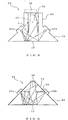
- the light-shielding plate 32 is provided as an extended portion of the lower side wall of the image conducting envelope 24. However, there may be the cases where only the light-shielding plate 32 is not enough to shield the light. The structures of preferable light-shielding members will be described for various cases.
- a light-shielding member 50 for this case has a structure such that the direct light from the lamps and the primary light reflected on a surface the bottom wall of the envelope 22 are effectively shielded.
- the light-shielding member 50 consists of a cylinder having a circular or polygonal cross-section extending downward from the peripheral part of the lens portion 34.
- the position of the lower end of the light-shielding member is determined by the conditions such that (1) a field viewed from the lens portion 34 to the object 12 is not shield, (2) the light from the lamps 30a and 30b is not prevented from illuminating the object 12, and (3) the direct light from the lamps 30a and 30b and the primary reflected light from the surface of the bottom wall of the envelope 22 are prevented.
- the direct light a from the light source and the primary reflected light b are shielded, but the primary reflected light is further reflected on the inner surface of the light-shielding member 50 to become a secondary reflected light c which impinges upon the lens portion 34.
- the reflectivity of the cloth stuck on the inner surface of the imaging box is 2%, the light intensity of the secondary reflected light is at most 0.04% of the direct light.
- the light-shielding member 50 has an effect enough to prevent the lens portion itself from being imaged by the camera and prevent a fog due to the secondary reflected light.
- a light-shielding member suited to an imaging box 54 in which the side walls of the image conducting envelope 52 are inclined different from that in Fig. 2.
- the light-shielding member consists of a horizontal light-shielding plate 56 having a circular opening in a field viewed from the lens portion to the object.
- the word " horizontal” is used in the case that the imaging box of Fig. 6 is positioned vertically. Correctly speaking, the light-shielding plate is positioned perpendicularly to an optical axis of the lens of the CCD camera 36.
- the horizontal light-shielding plate 56 even if the primary reflected light from the surface of the bottom wall of the object illuminating portion 22 is reflected on the inner surface of the image conducting envelope 52 to become a secondary reflected light c , the secondary reflected light is not reached to the lens portion 34 as the inner surface of the envelope 52 is inclined.
- this imaging box there is a risk such that a tertiary reflected light from the light-shielding plate impinges upon the lens. Assuming that the reflectivity of the cloth stuck on the inner surface of the imaging box is 2%, the light intensity of the tertiary reflected light is at most 0.0008% of the direct light, which may be neglected.
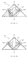
- Fig. 7 shows an example of an imaging box in which inclined light-shielding plates 58 are provided in addition to the horizontal light-shielding plate 56 in Fig. 6.
- Fig. 8 shows an example of an imaging box in which inclined light-shielding plates 60 are further provided in addition to the horizontal light-shielding plate 56 and the inclined light-shielding plates 58 in Fig. 7.
- the reflected light is not nearly reached to the lens portion due to the interaction of these light-shielding plates. This is because that the light which impinges between these light-shielding plates is reflected therebetween to be attenuated so that the intensity thereof is decreased substantially to zero.
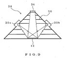
- FIG. 9 An example of the structure in which the above-described effects may simply be realized is shown in Fig. 9.
- a plurality of horizontal light-shielding plates 56 are provided.
- the horizontal light-shielding plates 56 are stucked as shown in the figure, so that the reflected light is attenuated and does not reach to the lens portion 34.
- inclined light-shielding plates may be combined to the plurality of horizontal light-shielding plates.
- the shape of the object illuminating envelope is truncated pyramid, and therefore the peripheral wall of the lower portion of the object illuminating envelope extends outward. If there is no such extended part, then the object illuminating envelope may be further compact.
- Figs. 10A and 10B show the cross-sectional views of imaging boxes having the structure described above.
- the structure in Fig. 10A corresponds to the imaging boxes in Figs. 2, 4 and 5, and the structure in Fig. 10B the imaging boxes in Figs. 6, 7, 8 and 9.
- Reference numeral 62 in the figures designates the object illuminating envelope.
- FIG. 11 there is shown a plan view of a modification of the imaging box in Fig.2.
- the walls to which the light source devices 29a and 29b are attached are inclined with respect to the optical axis of the lens, and residual walls are parallel with the optical axis of the lens.
- Reference numerals 64a and 64b denote the inclined walls on both sides of the object illuminating envelope.
- the imaging area of the object is 100mm ⁇ 100mm in the imaging box of each embodiment described above
- the imaging area may be extended by enlarging the size of the imaging box and increasing the amount of illumination of the light source.
- the positional relation among components in the imaging box may be realized by similarly enlarging a rectangular equilateral triangle with the distance A between the lens portion and the object being as a reference.
- the tolerance of ⁇ 10% may be allowed to the deviation of the shape of the triangle. Even if the positional relation among components is over the range of the tolerance, the requirement is satisfied where the direct light and the primary reflected light do not impinge upon the camera lens portion. While two line fluorescent lamps are used, one ring lamp may be used.
- the imaging box 40 in Fig. 4 is used.
- the CCD camera 36 is attached to the imaging box 40.
- the imaging box thus comprising the CCD camera is positioned with the window 42 thereof being contacted to one surface of the window glass plate 44 to be evaluated.
- a panel 46 covered by a black cloth of low reflectivity and non-gloss is contacted to the other surface of the window glass plate 44.
- a color image of the surface area of 100mm ⁇ 100mm of the window glass plate is taken by the CCD camera.
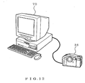
- the data for the color image taken by the CCD camera 36 is transferred to a personal computer 70 in a data format (JPG format, TIF format, etc.) supported by an image processing software.
- the personal computer 70 comprises a central processing unit and a memory.
- FIG. 13 shows a flow chart illustrating an image processing and analysis by means of the personal computer.
- the color image data from the CCD camera 36 is stored in the memory of the computer 70.
- the color image denoted by the color image data may be displayed on a display to be observed by an inspector.
- the central processing unit reads the color image data from the memory to convert it into a monochromatic image data showing the lightness of the surface of the window glass plate (Step S1).
- the monochromatic image data is stored in the memory.
- a monochromatic image denoted by the monochromatic image data may be displayed on a display to be observed by an inspector.
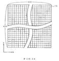
- the central processing unit reads the monochromatic image data from the memory to divide the monochromatic image of 100mm ⁇ 100mm denoted by the monochromatic image data into 400 ⁇ 400 meshes as shown in Fig. 14, thereby forming a dot matrix in which a divided one region (0.25mm ⁇ 0.25mm) is dealt as one dot.
- an X-Y coordinate is shown to indicate the extending directions of the dot matrix.
- One dot 72 is a minimum unit in an analysis of lightness distribution described above.
- the size of a minimum unit in an analysis of lightness distribution is selected so that the surface contamination is represented most effectively and efficiently. It is preferable to select the size of a minimum unit in an analysis of lightness distribution to be 1 - 1/10 times the size of contamination to be evaluated so that the surface contamination may be represented most effectively and efficiently. It is not preferable that the ratio of the size of a minimum unit to that of contamination is larger than 1, because the resolution in the representation of contamination, i.e., an evaluation accuracy becomes low. It is also not preferable that the ratio of the size of a minimum unit to that of contamination is lower than 1/10, because an evaluation accuracy does not become so high compared with the increasing of the amount of information to be processed.
- the dot size of 0.25mm ⁇ 0.25mm is selected in the example described above. This is because the size of deposition contamination to be evaluated is 0.5mm ⁇ 0.5mm, so that the surface contamination may be most effectively and efficiently represented when the minimum unit in the lightness distribution analysis is selected to be 1/2 times the size 0.5mm ⁇ 0.5mm
- the central processing unit obtains lightness every dot of the dot matrix (Step S2), thereby a lightness data for 400 ⁇ 400 dots is obtained.
- the lightness data is stored in the memory.
- contamination index denoting the level of surface contamination of a window glass plate is analyzed from the lightness data.
- an inspector displays a monochromatic image on the display and selects the contaminated area to be analyzed while looking at the monochromatic image on the display (Step S3).
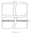
- the contaminated area to be analyzed is one-dimensional region extending in an X-direction on the display, i.e., one-dimensional region having 400-dot width in an X-direction and 1-dot width in a Y-direction on the dot matrix in Fig. 14.
- the area to be evaluated in the dot matrix is shown by a hatched region.
- the central processing unit of the computer acquires the lightness data of selected one-dimensional region from the memory (Step S4), and scans said one-dimensional region to create a lightness distribution data (Step S5).
- the central processing unit may form a graph of lightness distribution from the one-dimensional lightness distribution data to display it on the display.
- the lightness distribution has dispersion based on the surface contamination of a window glass plate, which dispersion may be recognized in a visual manner from the lightness distribution graph.
- the central processing unit calculates a standard deviation which is an index showing the level of dispersion of lightness (Step S6).
- the standard deviation is used as "a contamination index" for evaluating the contamination. Lager the standard deviation of lightness, higher the level of contamination becomes. Therefore, an inspector may recognize the level of contamination for a window glass plate from "a contamination index”.
- a self-cleaning glass plate i.e., a thin film including titanium oxide is formed thereon
- an ordinary float glass plate are contaminated by an accelerated contamination test and are analyzed for comparison by means of a contamination evaluating method described hereinbefore.
- Contaminated glass plate samples used for the analysis are made as follows. Glass plate samples of a self-cleaning glass plate and an ordinary float glass plate are prepared. The glass plate samples are cleaned by an ultrasonic cleaning in ethanol (40°C, 10 minutes), are cleaned using a sponge including a detergent for glass (Goods Name; Glass Mypet, made by Kao Company Ltd.), and completely linsed by water. The water on the samples is wiped by a non-woven fabric cloth (Goods Name; Bencot, made by Asahikasei Company Ltd.), and the samples are illuminated by ultraviolet (UV) light (a black light lamp is used, 3mW/cm 2 , 2 hours).
- UV ultraviolet
- Contaminated liquid is sprayed on the samples for three seconds by means of an electric spray gun from the position where 800mm is far from the samples.
- the contaminated liquid consists of pure water in which contaminants (carbon black 5%, yellow ocher 67.5%, baked loam 22.5%, and silica powder 5.0%) are dispersed in solid concentration of 0.03%, the contaminants being defined in Japanese Industrial Standards (JISZ8901).
- JISZ8901 Japanese Industrial Standards
- the surfaces of the samples are dried by means of a dryer for two minutes.
- the spray and dry steps described above are repeated ten times.
- the color images of the self-cleaning glass plate samples and ordinary float glass plate samples thus contaminated are taken by means of the camera and are displayed on the computer display. According to the visual impression of an inspector for the image on the display, the contamination for the float glass plate samples has nonuniformity and the level of contamination for the float glass plate sample is larger than that of the self-cleaning glass plate sample.
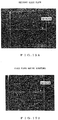
- FIGs. 16A and 16B there are shown the monochromatic images of the self-cleaning glass plate sample and ordinary float glass plate sample processed by the personal computer and displayed on a display, respectively.
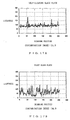
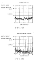
- FIGs. 17A and 17B there are shown the graphs illustrating the lightness distribution in one-dimensional region (255 dots) which is an analyzing area in an X-direction selected in the monochromatic image. It is understood from the lightness distribution graphs that the dispersion of the lightness of the ordinary float glass plate sample is larger than that of the self-cleaning glass plate sample.
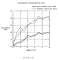
- "Contamination indexes" calculated by the computer are 24.9 for the self-cleaning glass plate sample and 34.9 for the ordinary float glass plate sample, respectively. Calculated contamination indexes are matched to the visual impressions of an inspector for the monochromatic images on the display.
- Fig. 18 shows the graph in which the results of the analysis are plotted.
- the contamination evaluating method described in the embodiments is applied to a glass plate which has the scratch contamination.
- Figs. 19A and 19B there are shown the monochromatic images of two ordinary glass plate samples having no scratches and having scratches, respectively, the monochromatic images being formed by the personal computer and displayed on the display.
- Figs. 20A and 20B there are shown the graphs indicating the lightness distribution in one-dimensional region which is an analyzing area in an X-direction selected in the monochromatic image. It is understood from the lightness distribution graphs that the lightness in the area having scratches is largely varied.
- "Contamination indexes" calculated by the computer are 11.23 for the glass plate sample having no scratches and 30.68 for the glass plate sample having scratches. It is understood that a contamination index becomes large when the glass plate sample has scratches thereon.
- the size of the minimum unit may be changed based on the size (width) of scratch.
- the size of the minimum unit may be 1-1/10 times the size of scratch to be evaluated.
- samples A , B , C and D are prepared as the objects to be evaluated.
- the samples A , B and C are ordinary float glass plates, and the sample D is a self-cleaning glass plate.
- the cleaning step of a glass plate and the spraying step of contaminated liquid to a glass plate are not conducted.
- step of cleaning of a glass pate is not conducted, and the step of spraying of contaminated liquid to a glass plate and drying thereof is repeated one time, ten times, and one time, respectively.
- the samples A , B and C look like contaminated in this order. While the level of contamination for the sample D is substantially the same as the sample B , the sample B looks like more contaminated than the sample D in a visual impression.
- Transmittance, haze factor, and color difference are measured in a conventional evaluation method. These measured values are shown in Table 1 together with the values of contamination indexes obtained by the evaluation method according to the present invention.
- the values of contamination indexes are obtained by measuring contamination indexes of ten lines of one-dimensional region (399 dots) at intervals of 1cm and averaging them in order to evaluate two dimensional distribution.
- the transmittance and haze factor are obtained by measuring five points using SUGA Haze Metar and averaging measured values.
- the color difference is obtained by measuring five points using MINOLTA CR3000 and averaging measured values.
- the haze factor is correlated to the level of contamination where the kinds of glass plates are the same, but is not correlated to the level of contamination where the kinds of glass plates are different.
- the color difference is largely controlled by the perceived color of a glass plate itself and is not suitable for the contamination evaluation.
- Contamination indexes according to the present invention are 18.1 for the sample A , 30.6 for the sample B , 39.6 for the sample C , and 21.4 for the sample D , respectively. These contamination indexes are matched to the visual impressions for contamination.
- the standard deviation of lightness of an object to be evaluated are used as contamination indexes for evaluating the contamination.
- the standard deviation of maximal lightness value of an object to be evaluated is used as a second contamination index.
- the standard deviation of maximal lightness value means, herein, a standard deviation of a series of data consisting of maximal values derived from the lightness data. That is, where there are many contaminated areas which are bright, the glass plate looks like more contaminated as the areas each having a maximal lightness have a large irregularity in their lightness.
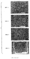
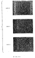
- the samples E , F and G are ordinary float glass plates. These contaminated samples are prepared by contaminating the surfaces of the glass plates in a manner described in the embodiment 1. According to the visual impression to these samples, the samples E , F and G look like contaminated in this order.
- FIGs. 22A , 22B and 22C there are shown the monochromatic images of the contaminated samples E , F and G processed by the personal computer and displayed on a display, respectively.
- FIGs. 23A , 23B and 23C there are shown the graphs indicating the lightness distribution in one-dimensional region (255 dots) which is an analyzing area in an X-direction selected in the monochromatic image.
- Contamination indexes calculated by the computer are 50.8 for the sample E , 53.2 for the sample F , and 48.4 for the sample G , respectively.
- a visual evaluation and a contamination index show an opposite relation in the samples F and G .
- the second contamination indexes are calculated by the computer, resulting in 47.1 for the sample E , 50.2 for the sample F , and 53.0 for the sample G , respectively.
- a visual evaluation and a second contamination index show a matched relation in the samples F and G .
- the second contamination index is used for the criterion for an evaluation of the contamination when objects to be evaluated each thereof has a contamination index larger than 40 are compared.
- an inspector may optionally select an area to be evaluated. If an area to be selected is not changed, analysis data has a repeatability. It is therefore possible to realize the quantification of contamination which is close to the visual impression of human being.
- an analysis is conducted by varying a minimum unit in analysis of lightness distribution based on the size of contamination to be valuated such as deposits and scratches, so that the difference in a surface contamination is clearly represented.
- An imaging box of the present invention may be easily set because the box is integrated with a camera.
- the positional relation among a camera, an object, and a light source is fixed by using the imaging box, so that the condition of taking an image is highly repeatable.
- the portability and mobility of the imaging box is high, so that it is possible to take an image of a surface of a window glass or wall of a building.
Landscapes
- Engineering & Computer Science (AREA)
- Physics & Mathematics (AREA)
- General Physics & Mathematics (AREA)
- Computer Vision & Pattern Recognition (AREA)
- Theoretical Computer Science (AREA)
- Chemical & Material Sciences (AREA)
- Health & Medical Sciences (AREA)
- Life Sciences & Earth Sciences (AREA)
- Quality & Reliability (AREA)
- Analytical Chemistry (AREA)
- Biochemistry (AREA)
- General Health & Medical Sciences (AREA)
- Immunology (AREA)
- Pathology (AREA)
- Investigating Materials By The Use Of Optical Means Adapted For Particular Applications (AREA)
- Spectrometry And Color Measurement (AREA)
Abstract
Description
| Sample | A | B | C | D | |
| Transmittance(%) | 91.3 | 91.2 | 90.4 | 78.4 | SUGA Haze Meter (Average of 5 measured values) |
| Haze factor(%) | 0.1 | 0.9 | 5.4 | 2.4 | SUGA Haze Meter (Average of 5 measured values) |
| Color difference | 27.4 | 27.7 | 29.0 | 48.7 | MINOLTA CR300 (Average of 5 measured values) |
| Contamination Index | 18.1 | 30.6 | 39.6 | 21.4 |
Claims (33)
- A method for evaluating the contamination of a surface of an object comprising the steps of:taking an image of the surface of the object; andevaluating the contamination based on the distribution of lightness of the image obtained by the step of taking an image.
- A method for evaluating the contamination of a surface of an object comprising the steps of:taking an image of the surface of the object;dividing the image obtained by the step of taking an image into a dot matrix to obtain lightness per dot;selecting an area to be evaluated on the dot matrix;calculating a standard deviation of lightness from the distribution of lightness of the selected area as a contamination index; andevaluating the contamination based on the contamination index.
- A method for evaluating the contamination of a surface of an object comprising the steps of:taking a color image of the surface of the object;converting a color image data denoting the color image obtained by the step of taking an color image into a monochromatic image data;dividing a monochromatic image denoted by the monochromatic image data into a dot matrix to obtain lightness per dot;selecting an area to be evaluated on the dot matrix;calculating a standard deviation of lightness from the distribution of lightness of the selected area as a contamination index; andevaluating the contamination based on the contamination index.
- A method for evaluating the contamination of a surface of an object comprising the steps of:taking an image of the surface of the object;dividing the image obtained by the step of taking an image into a dot matrix to obtain lightness per dot;selecting an area to be evaluated on the dot matrix;calculating a standard deviation of lightness from the distribution of lightness of the selected area as a first contamination index;calculating a standard deviation of maximal value of lightness from the distribution of maximal value of lightness of the selected area as a second contamination index, when the first contamination index is larger than a predetermined value; andevaluating the contamination based on the second contamination index.
- A method for evaluating the contamination of a surface of an object comprising the steps of:taking a color image of the surface of the object;converting a color image data denoting the color image obtained by the step of taking an color image into a monochromatic image data;dividing a monochromatic image denoted by the monochromatic image data into a dot matrix to obtain lightness per dot;selecting an area to be evaluated on the dot matrix;calculating a standard deviation of lightness from the distribution of lightness of the selected area as a first contamination index;calculating a standard deviation of maximal value of lightness from the distribution of maximal value of lightness of the selected area as a second contamination index, when the first contamination index is larger than a predetermined value; andevaluating the contamination based on the second contamination index.
- A method according to any one of claims 2-5 wherein the area to be evaluated is a one-dimensional region.
- A method according to any one of claims 2-5 wherein the area to be evaluated is a two-dimensional region.
- A method according to claim 6 wherein the size of the dot is selected to be 1-1/10 times the size of contamination to be evaluated.
- A method according to claim 7 wherein the size of the dot is selected to be 1-1/10 times the size of contamination to be evaluated.
- A method according to any one of claims 1-5 wherein the step of taking an image of the surface of the object is conducted by a solid state imaging camera.
- A method according to any one of claims 1-5 wherein the step of taking an image of the surface of the object is conducted by an optical camera.
- A method according to claim 2 wherein the steps of dividing the obtained image into a dot matrix to obtain lightness per dot, selecting an area to be evaluated on the dot matrix, and calculating the contamination index from the distribution of lightness of the selected area are conducted in an image processing apparatus.
- A method according to claim 3 wherein the steps of converting a color image data denoting the obtained color image into a monochromatic image data, dividing a monochromatic image denoted by the monochromatic image data into a dot matrix to obtain lightness per dot, selecting an area to be evaluated on the dot matrix, and calculating the contamination index from the distribution of lightness of the selected area are conducted in an image processing apparatus.
- A method according to claim 4 wherein the steps of dividing the obtained image into a dot matrix to obtain lightness per dot, selecting an area to be evaluated on the dot matrix, and calculating the first contamination index from the distribution of lightness of the selected area and the second contamination index of maximal value of lightness from the distribution of maximal value of lightness of the selected area are conducted in an image processing apparatus.
- A method according to claim 5 wherein the steps of converting a color image data denoting the obtained color image into a monochromatic image data, dividing a monochromatic image denoted by the monochromatic image data into a dot matrix to obtain lightness per dot, selecting an area to be evaluated on the dot matrix, and calculating the first contamination index from the distribution of lightness of the selected area and the second contamination index of maximal value of lightness from the distribution of maximal value of lightness of the selected area are conducted in an image processing apparatus.
- A method according to any one of claims 12-15 wherein the image processing apparatus is a personal computer.
- An imaging box used for a method of evaluating the contamination on a surface of an object based on lightness distribution of an image of the surface of the object taken by a camera comprising:wherein the first and second envelopes construct together one space.a first box-shaped envelope having an opening in which a lens portion of the camera is fitted with being faced inward, an inner surface of the first envelope having a low reflectivity structure;a second box-shaped envelope in which an object is positioned in front of the lens portion, the second envelope including a light source inside or outside thereof for illuminating the object from a direction oblique thereto and an inner surface of the second envelope having a low reflectivity structure; anda light-shielding member, provided in the first envelope and/or the second envelope, for preventing direct and reflected light from the light source from impinging upon the lens portion of the camera, an inner surface of the light-shielding member having a low reflectivity structure;
- An imaging box used for a method of evaluating the contamination on a surface of an object based on lightness distribution of an image of the surface of the object taken by a camera comprising:wherein the first and second envelopes construct together one space.a first box-shaped envelope having an opening in which a lens portion of the camera is fitted with being faced inward, an inner surface of the first envelope having a low reflectivity structure;a second box-shaped envelope having a window opposed to the object in front of the lens portion, the second envelope including a light source inside or outside thereof for illuminating the object from a direction oblique thereto and an inner surface of the second envelope having a low reflectivity structure; anda light-shielding member, provided in the first envelope and the second envelope, for preventing direct and reflected light from the light source from impinging upon the lens portion of the camera, an inner surface of the light-shielding member having a low reflectivity structure;
- An imaging box according to claim 17 or 18 wherein a wall to which at least the light source is attached is inclined with respect to an optical axis of the lens portion of the camera.
- An imaging box according to claim 17 or 18 wherein the shape of the first envelope is cube or rectangular parallelepiped, and the shape of the second envelope is truncated pyramid.
- An imaging box according to claim 17 or 18 wherein the shape each of the first and second envelopes is truncated pyramid.
- An imaging box according to claim 20 wherein the first envelope is structured so that the peripheral wall of the lower portion of the truncated pyramid is parallel with the optical axis of the lens portion of the camera.
- An imaging box according to claim 21 wherein the first envelope is structured so that the peripheral wall of the lower portion of the truncated pyramid is parallel with the optical axis of the lens portion of the camera.
- An imaging box according to claim 17 or 18 wherein a black cloth of low reflectivity and non-gloss is stuck on the inner surfaces of the first and second envelopes, and a black cloth of low reflectivity and non-gloss is also stuck on the surface of the shielding member.
- An imaging box according to claim 17 or 18 wherein the light-shielding member does not shield a field viewed from the lens portion to the object and does not prevent the light from illuminating the object.
- An imaging box according to claim 25 wherein the light-shielding member includes a cylinder extending downward from the peripheral part of the lens portion.
- An imaging box according to claim 25 wherein the light-shielding member include a light-shielding plate perpendicular to an optical axis of the lens portion of the camera.
- An imaging box according to claim 25 wherein the light-shielding member includes one light-shielding plate perpendicular to an optical axis of the lens portion of the camera and one light-shielding plate inclined to an optical axis of the lens portion of the camera.
- An imaging box according to claim 25 wherein the light-shielding member includes one light-shielding plate perpendicular to an optical axis of the lens portion of the camera and two light-shielding plates inclined to an optical axis of the lens portion of the camera, respectively.
- An imaging box according to claim 25 wherein the light-shielding member includes a plurality of light-shielding plates perpendicular to an optical axis of the lens of the camera, respectively.
- An imaging box according to claim 25 wherein the light-shielding member includes a plurality of light-shielding plates perpendicular to an optical axis of the lens of the camera, respectively, and a plurality of light-shielding plates inclined to an optical axis of the lens of the camera, respectively.
- An imaging box according to claim 17 or 18 wherein the light source includes two line fluorescent lamps illuminating the object from oblique directions, respectively.
- An imaging box according to claim 17 or 18 wherein the light source includes one ring fluorescent lamp illuminating the object from oblique direction.
Applications Claiming Priority (5)
| Application Number | Priority Date | Filing Date | Title |
|---|---|---|---|
| JP2001227224 | 2001-07-27 | ||
| JP2001227224 | 2001-07-27 | ||
| JP2001262374 | 2001-07-30 | ||
| JP2001262374 | 2001-07-30 | ||
| PCT/JP2002/007526 WO2003010525A1 (en) | 2001-07-27 | 2002-07-25 | Method for evaluating contamination of object surface and imaging box used for this method |
Publications (2)
| Publication Number | Publication Date |
|---|---|
| EP1424551A1 true EP1424551A1 (en) | 2004-06-02 |
| EP1424551A4 EP1424551A4 (en) | 2008-07-09 |
Family
ID=26619392
Family Applications (1)
| Application Number | Title | Priority Date | Filing Date |
|---|---|---|---|
| EP02751672A Withdrawn EP1424551A4 (en) | 2001-07-27 | 2002-07-25 | Method for evaluating contamination of object surface and imaging box used for this method |
Country Status (4)
| Country | Link |
|---|---|
| US (1) | US7343038B2 (en) |
| EP (1) | EP1424551A4 (en) |
| JP (1) | JPWO2003010525A1 (en) |
| WO (1) | WO2003010525A1 (en) |
Cited By (7)
| Publication number | Priority date | Publication date | Assignee | Title |
|---|---|---|---|---|
| GB2415776A (en) * | 2004-06-28 | 2006-01-04 | Carglass Luxembourg Sarl Zug | Investigation of vehicle glazing panels |
| WO2006132698A3 (en) * | 2005-04-29 | 2007-02-01 | Gsi Group Corp | System for inspecting wafers in a laser marking system with an illumination system illuminating a surface of the wafer at angle between 45° and 70° with respect to this surface |
| GB2447166A (en) * | 2004-06-28 | 2008-09-03 | Carglass Luxembourg Sarl Zug | Investigation of vehicle glazing panels |
| WO2008129299A3 (en) * | 2007-04-23 | 2008-12-11 | Belron Hungary Kft Zug Branch | Investigation system and technique |
| CN102565091A (en) * | 2010-07-26 | 2012-07-11 | 东芝移动显示器有限公司 | Inspection apparatus and inspection method |
| RU2682566C2 (en) * | 2017-05-17 | 2019-03-19 | Владислав Викторович Семенов | Dust formation detection device for printed circuit boards of radio electronic equipment |
| WO2023110573A1 (en) * | 2021-12-17 | 2023-06-22 | Elkamet Kunststofftechnik Gmbh | Device for detecting surface defects on a surface of a test body, and method for operating the device |
Families Citing this family (14)
| Publication number | Priority date | Publication date | Assignee | Title |
|---|---|---|---|---|
| US7014114B2 (en) * | 2003-10-02 | 2006-03-21 | Symbol Technologies, Inc. | Image capture device for and method of electro-optically reading indicia at low ambient light levels |
| JP2005291878A (en) * | 2004-03-31 | 2005-10-20 | Shin Nisseki Ekisho Film Kk | Inspection method of optical film |
| US7877003B2 (en) * | 2007-06-20 | 2011-01-25 | Microscan Systems, Inc. | Devices, systems, and methods regarding images |
| US8768159B2 (en) | 2009-07-10 | 2014-07-01 | Microscan Systems, Inc. | Combination dark field and bright field illuminator |
| FI124452B (en) * | 2010-07-09 | 2014-09-15 | Teknologian Tutkimuskeskus Vtt | Method and apparatus for measuring color and other properties of a surface |
| JP6234044B2 (en) * | 2013-03-29 | 2017-11-22 | 大和ハウス工業株式会社 | Exterior material deterioration judging method and judging device |
| JP6438703B2 (en) * | 2014-08-21 | 2018-12-19 | バンドー化学株式会社 | Foreign matter inspection apparatus, foreign matter inspection system, and foreign matter inspection method |
| WO2016060165A1 (en) * | 2014-10-17 | 2016-04-21 | 旭硝子株式会社 | Transparent member, method for manufacturing transparent member and method for evaluating degree of soiling of surface of transparent member |
| JP2016114452A (en) * | 2014-12-15 | 2016-06-23 | 株式会社NejiLaw | Imaging system |
| WO2020158340A1 (en) * | 2019-02-01 | 2020-08-06 | パナソニックIpマネジメント株式会社 | Inspection device and inspection method |
| EP3933387B1 (en) * | 2019-02-27 | 2023-10-18 | Daikin Industries, Ltd. | Information providing system |
| CN111948214A (en) * | 2020-07-17 | 2020-11-17 | 同济大学 | Device and method for classifying image pollution levels |
| JP7488502B2 (en) * | 2022-06-10 | 2024-05-22 | 日本製鉄株式会社 | Observation device for hot-dip galvanized steel sheet and observation method for hot-dip galvanized steel sheet |
| JPWO2025037596A1 (en) * | 2023-08-17 | 2025-02-20 |
Family Cites Families (23)
| Publication number | Priority date | Publication date | Assignee | Title |
|---|---|---|---|---|
| JPS4989428A (en) | 1972-12-27 | 1974-08-27 | ||
| US4574393A (en) * | 1983-04-14 | 1986-03-04 | Blackwell George F | Gray scale image processor |
| EP0226430A3 (en) * | 1985-12-13 | 1988-03-23 | Unisearch Limited | Measurement of foreign matter in fibre assemblies |
| JPH0792437B2 (en) | 1986-12-05 | 1995-10-09 | 日本電気株式会社 | Surface shape observation device |
| JPH02128147A (en) | 1988-11-07 | 1990-05-16 | Nissan Motor Co Ltd | Window glass surface evaluator |
| US4931657A (en) * | 1989-04-13 | 1990-06-05 | Macmillan Bloedel Limited | On-line texture sensing |
| JP2996263B2 (en) * | 1991-08-14 | 1999-12-27 | 日立電子エンジニアリング株式会社 | Optimal threshold value determination method for foreign object detection |
| JPH0581697U (en) | 1992-03-31 | 1993-11-05 | アンリツ株式会社 | Appearance inspection device |
| JPH0643108A (en) * | 1992-07-28 | 1994-02-18 | Dainippon Printing Co Ltd | Foreign object inspection apparatus and method |
| DE4322870C1 (en) * | 1993-07-09 | 1994-09-29 | Tuchenhagen Otto Gmbh | Method and arrangement for assessing the success of cleaning procedures on contaminated surfaces |
| DE4410603C1 (en) * | 1994-03-26 | 1995-06-14 | Jenoptik Technologie Gmbh | Detecting faults during inspection of masks, LCDs, circuit boards and semiconductor wafers |
| JPH08323965A (en) * | 1995-05-31 | 1996-12-10 | Dainippon Printing Co Ltd | Color image inspection method and apparatus |
| JPH09101265A (en) * | 1995-10-05 | 1997-04-15 | Furukawa Electric Co Ltd:The | Automatic inspection method for surface defects of Al plate |
| JPH09163133A (en) * | 1995-12-12 | 1997-06-20 | Fuji Photo Film Co Ltd | Film scanner device |
| JPH09189664A (en) * | 1996-01-09 | 1997-07-22 | Rohm Co Ltd | Appearance inspection method for transparent bodies |
| JPH10123066A (en) * | 1996-10-17 | 1998-05-15 | Asahi Glass Co Ltd | Singularity detection apparatus and method |
| JPH1114323A (en) * | 1997-06-25 | 1999-01-22 | Asahi Chem Ind Co Ltd | Pattern inspection method and pattern inspection device |
| JPH1164970A (en) | 1997-08-22 | 1999-03-05 | Gokou Internatl Corp:Kk | High magnification camera |
| IL131092A (en) * | 1999-07-25 | 2006-08-01 | Orbotech Ltd | Optical inspection system |
| JP2001041899A (en) | 1999-07-27 | 2001-02-16 | Toshiba Corp | Soil condition identification device for paper sheets |
| US6487321B1 (en) * | 1999-09-16 | 2002-11-26 | Applied Science Fiction | Method and system for altering defects in a digital image |
| JP3421649B2 (en) | 2000-11-30 | 2003-06-30 | 旭化成株式会社 | Appearance inspection method |
| JP4763905B2 (en) * | 2001-03-06 | 2011-08-31 | オリンパス株式会社 | Encoded image reader |
-
2002
- 2002-07-25 EP EP02751672A patent/EP1424551A4/en not_active Withdrawn
- 2002-07-25 WO PCT/JP2002/007526 patent/WO2003010525A1/en not_active Ceased
- 2002-07-25 US US10/484,943 patent/US7343038B2/en not_active Expired - Fee Related
- 2002-07-25 JP JP2003515847A patent/JPWO2003010525A1/en not_active Withdrawn
Cited By (13)
| Publication number | Priority date | Publication date | Assignee | Title |
|---|---|---|---|---|
| GB2415776B (en) * | 2004-06-28 | 2009-01-28 | Carglass Luxembourg Sarl Zug | Investigation of vehicle glazing panels |
| GB2447166A (en) * | 2004-06-28 | 2008-09-03 | Carglass Luxembourg Sarl Zug | Investigation of vehicle glazing panels |
| GB2447166B (en) * | 2004-06-28 | 2009-01-07 | Carglass Luxembourg Sarl Zug | Investigation of vehicle glazing panels |
| GB2415776A (en) * | 2004-06-28 | 2006-01-04 | Carglass Luxembourg Sarl Zug | Investigation of vehicle glazing panels |
| US7868291B2 (en) | 2004-06-28 | 2011-01-11 | Carglass Luxembourg Sarl-Zug Branch | Investigation of vehicle glazing panels |
| WO2006132698A3 (en) * | 2005-04-29 | 2007-02-01 | Gsi Group Corp | System for inspecting wafers in a laser marking system with an illumination system illuminating a surface of the wafer at angle between 45° and 70° with respect to this surface |
| US7315361B2 (en) | 2005-04-29 | 2008-01-01 | Gsi Group Corporation | System and method for inspecting wafers in a laser marking system |
| WO2008129299A3 (en) * | 2007-04-23 | 2008-12-11 | Belron Hungary Kft Zug Branch | Investigation system and technique |
| CN102565091A (en) * | 2010-07-26 | 2012-07-11 | 东芝移动显示器有限公司 | Inspection apparatus and inspection method |
| US8854615B2 (en) | 2010-07-26 | 2014-10-07 | Japan Display Inc. | Inspection apparatus and inspection method |
| CN102565091B (en) * | 2010-07-26 | 2015-05-20 | 株式会社日本显示器 | Inspection device and inspection method |
| RU2682566C2 (en) * | 2017-05-17 | 2019-03-19 | Владислав Викторович Семенов | Dust formation detection device for printed circuit boards of radio electronic equipment |
| WO2023110573A1 (en) * | 2021-12-17 | 2023-06-22 | Elkamet Kunststofftechnik Gmbh | Device for detecting surface defects on a surface of a test body, and method for operating the device |
Also Published As
| Publication number | Publication date |
|---|---|
| JPWO2003010525A1 (en) | 2004-11-18 |
| US7343038B2 (en) | 2008-03-11 |
| EP1424551A4 (en) | 2008-07-09 |
| WO2003010525A1 (en) | 2003-02-06 |
| US20040175026A1 (en) | 2004-09-09 |
Similar Documents
| Publication | Publication Date | Title |
|---|---|---|
| US7343038B2 (en) | Method for evaluating contamination on surface of object and imaging box used for the method | |
| KR101338576B1 (en) | Defect inspection device for inspecting defect by image analysis | |
| CN201795992U (en) | Device for inspecting transparent glass plate with first surface and second surface | |
| US8040502B2 (en) | Optical inspection of flat media using direct image technology | |
| US7272253B2 (en) | Method for non-destructive inspection, apparatus thereof and digital camera system | |
| KR100399507B1 (en) | How to recognize and evaluate defects in reflective surface coatings | |
| US5854674A (en) | Method of high speed, high detection sensitivity inspection of repetitive and random specimen patterns | |
| US20090290781A1 (en) | Illuminating device for cylindrical objects, surface inspection method implemented therewith and computer program product | |
| CN113686879A (en) | Optical film defect visual detection system and method | |
| JP2021113744A (en) | Imaging system | |
| JP2004037248A (en) | Inspection device and inspection method of through hole | |
| US12066387B2 (en) | Micro scale image capture system | |
| JPWO2007132925A1 (en) | Surface inspection device | |
| JPS61256237A (en) | Defect inspection for cyclic pattern | |
| KR100249270B1 (en) | Method and system for inspecting unevenness | |
| JP2792517B2 (en) | Sample inspection method | |
| JPH07128032A (en) | Method and apparatus for inspecting surface waviness of plate-shaped material | |
| WO2019176614A1 (en) | Image processing device, image processing method, and computer program | |
| JPH0963547A (en) | Inspection method for can opening | |
| JP2004117290A (en) | Inspection method and apparatus for periodic pattern | |
| KR100249597B1 (en) | Optical nonuniformity inspection device and optical nonuniformity inspection method | |
| KR100249599B1 (en) | Apparatus for inspecting optical uniformity and method therefor | |
| JPH04309834A (en) | Lens inspection device | |
| KR100890050B1 (en) | Pattern checker | |
| JP2004125471A (en) | Method and apparatus for inspecting unevenness of periodic pattern |
Legal Events
| Date | Code | Title | Description |
|---|---|---|---|
| PUAI | Public reference made under article 153(3) epc to a published international application that has entered the european phase |
Free format text: ORIGINAL CODE: 0009012 |
|
| 17P | Request for examination filed |
Effective date: 20040216 |
|
| AK | Designated contracting states |
Kind code of ref document: A1 Designated state(s): AT BE BG CH CY CZ DE DK EE ES FI FR GB GR IE IT LI LU MC NL PT SE SK TR |
|
| AX | Request for extension of the european patent |
Extension state: AL LT LV MK RO SI |
|
| A4 | Supplementary search report drawn up and despatched |
Effective date: 20080611 |
|
| RIC1 | Information provided on ipc code assigned before grant |
Ipc: G01N 21/88 20060101ALI20080602BHEP Ipc: G01N 21/94 20060101AFI20080602BHEP |
|
| REG | Reference to a national code |
Ref country code: DE Ref legal event code: 8566 |
|
| 17Q | First examination report despatched |
Effective date: 20080915 |
|
| STAA | Information on the status of an ep patent application or granted ep patent |
Free format text: STATUS: THE APPLICATION IS DEEMED TO BE WITHDRAWN |
|
| 18D | Application deemed to be withdrawn |
Effective date: 20090127 |