EP1424482A2 - Fuel injection control device - Google Patents
Fuel injection control device Download PDFInfo
- Publication number
- EP1424482A2 EP1424482A2 EP03026837A EP03026837A EP1424482A2 EP 1424482 A2 EP1424482 A2 EP 1424482A2 EP 03026837 A EP03026837 A EP 03026837A EP 03026837 A EP03026837 A EP 03026837A EP 1424482 A2 EP1424482 A2 EP 1424482A2
- Authority
- EP
- European Patent Office
- Prior art keywords
- fuel injection
- amount
- timing
- exhaust gas
- gas temperature
- Prior art date
- Legal status (The legal status is an assumption and is not a legal conclusion. Google has not performed a legal analysis and makes no representation as to the accuracy of the status listed.)
- Granted
Links
Images


Classifications
-
- F—MECHANICAL ENGINEERING; LIGHTING; HEATING; WEAPONS; BLASTING
- F02—COMBUSTION ENGINES; HOT-GAS OR COMBUSTION-PRODUCT ENGINE PLANTS
- F02D—CONTROLLING COMBUSTION ENGINES
- F02D41/00—Electrical control of supply of combustible mixture or its constituents
- F02D41/02—Circuit arrangements for generating control signals
- F02D41/021—Introducing corrections for particular conditions exterior to the engine
- F02D41/0235—Introducing corrections for particular conditions exterior to the engine in relation with the state of the exhaust gas treating apparatus
- F02D41/024—Introducing corrections for particular conditions exterior to the engine in relation with the state of the exhaust gas treating apparatus to increase temperature of the exhaust gas treating apparatus
- F02D41/0245—Introducing corrections for particular conditions exterior to the engine in relation with the state of the exhaust gas treating apparatus to increase temperature of the exhaust gas treating apparatus by increasing temperature of the exhaust gas leaving the engine
-
- F—MECHANICAL ENGINEERING; LIGHTING; HEATING; WEAPONS; BLASTING
- F02—COMBUSTION ENGINES; HOT-GAS OR COMBUSTION-PRODUCT ENGINE PLANTS
- F02D—CONTROLLING COMBUSTION ENGINES
- F02D41/00—Electrical control of supply of combustible mixture or its constituents
- F02D41/30—Controlling fuel injection
- F02D41/38—Controlling fuel injection of the high pressure type
- F02D41/40—Controlling fuel injection of the high pressure type with means for controlling injection timing or duration
-
- F—MECHANICAL ENGINEERING; LIGHTING; HEATING; WEAPONS; BLASTING
- F02—COMBUSTION ENGINES; HOT-GAS OR COMBUSTION-PRODUCT ENGINE PLANTS
- F02D—CONTROLLING COMBUSTION ENGINES
- F02D2200/00—Input parameters for engine control
- F02D2200/02—Input parameters for engine control the parameters being related to the engine
- F02D2200/08—Exhaust gas treatment apparatus parameters
- F02D2200/0802—Temperature of the exhaust gas treatment apparatus
-
- F—MECHANICAL ENGINEERING; LIGHTING; HEATING; WEAPONS; BLASTING
- F02—COMBUSTION ENGINES; HOT-GAS OR COMBUSTION-PRODUCT ENGINE PLANTS
- F02D—CONTROLLING COMBUSTION ENGINES
- F02D2200/00—Input parameters for engine control
- F02D2200/02—Input parameters for engine control the parameters being related to the engine
- F02D2200/10—Parameters related to the engine output, e.g. engine torque or engine speed
- F02D2200/1006—Engine torque losses, e.g. friction or pumping losses or losses caused by external loads of accessories
-
- F—MECHANICAL ENGINEERING; LIGHTING; HEATING; WEAPONS; BLASTING
- F02—COMBUSTION ENGINES; HOT-GAS OR COMBUSTION-PRODUCT ENGINE PLANTS
- F02D—CONTROLLING COMBUSTION ENGINES
- F02D41/00—Electrical control of supply of combustible mixture or its constituents
- F02D41/02—Circuit arrangements for generating control signals
- F02D41/021—Introducing corrections for particular conditions exterior to the engine
- F02D41/0235—Introducing corrections for particular conditions exterior to the engine in relation with the state of the exhaust gas treating apparatus
- F02D41/027—Introducing corrections for particular conditions exterior to the engine in relation with the state of the exhaust gas treating apparatus to purge or regenerate the exhaust gas treating apparatus
- F02D41/029—Introducing corrections for particular conditions exterior to the engine in relation with the state of the exhaust gas treating apparatus to purge or regenerate the exhaust gas treating apparatus the exhaust gas treating apparatus being a particulate filter
-
- F—MECHANICAL ENGINEERING; LIGHTING; HEATING; WEAPONS; BLASTING
- F02—COMBUSTION ENGINES; HOT-GAS OR COMBUSTION-PRODUCT ENGINE PLANTS
- F02D—CONTROLLING COMBUSTION ENGINES
- F02D41/00—Electrical control of supply of combustible mixture or its constituents
- F02D41/30—Controlling fuel injection
- F02D41/38—Controlling fuel injection of the high pressure type
- F02D41/40—Controlling fuel injection of the high pressure type with means for controlling injection timing or duration
- F02D41/402—Multiple injections
- F02D41/403—Multiple injections with pilot injections
-
- Y—GENERAL TAGGING OF NEW TECHNOLOGICAL DEVELOPMENTS; GENERAL TAGGING OF CROSS-SECTIONAL TECHNOLOGIES SPANNING OVER SEVERAL SECTIONS OF THE IPC; TECHNICAL SUBJECTS COVERED BY FORMER USPC CROSS-REFERENCE ART COLLECTIONS [XRACs] AND DIGESTS
- Y02—TECHNOLOGIES OR APPLICATIONS FOR MITIGATION OR ADAPTATION AGAINST CLIMATE CHANGE
- Y02T—CLIMATE CHANGE MITIGATION TECHNOLOGIES RELATED TO TRANSPORTATION
- Y02T10/00—Road transport of goods or passengers
- Y02T10/10—Internal combustion engine [ICE] based vehicles
- Y02T10/12—Improving ICE efficiencies
-
- Y—GENERAL TAGGING OF NEW TECHNOLOGICAL DEVELOPMENTS; GENERAL TAGGING OF CROSS-SECTIONAL TECHNOLOGIES SPANNING OVER SEVERAL SECTIONS OF THE IPC; TECHNICAL SUBJECTS COVERED BY FORMER USPC CROSS-REFERENCE ART COLLECTIONS [XRACs] AND DIGESTS
- Y02—TECHNOLOGIES OR APPLICATIONS FOR MITIGATION OR ADAPTATION AGAINST CLIMATE CHANGE
- Y02T—CLIMATE CHANGE MITIGATION TECHNOLOGIES RELATED TO TRANSPORTATION
- Y02T10/00—Road transport of goods or passengers
- Y02T10/10—Internal combustion engine [ICE] based vehicles
- Y02T10/40—Engine management systems
Definitions
- the amount of fuel injection is indicated by the horizontal axis and the torque output of the engine is indicated by the vertical axis.
- the line A shows a torque output when the fuel injection timing is conducted at normal timing.
- the line B shows a torque output when the fuel injection timing is retarded for a predetermined period.
- the controller may determine the retardation period based on the load condition and/or the rotational speed of the internal combustion engine and may also determine the amount of fuel injection which is increased compared to the basic fuel injection amount in accordance with the load condition and/or the rotational speed.
- the retarded timing and increased amount of the fuel injection which depend on the load condition and the rotational speed of the internal combustion engine, may be respectively stored into the control means in the form of maps, and the controller may determine the actual timing and the actual amount of the fuel injection in reference to these maps.
- Each fuel injector 6 is connected with the controller 12 and also controlled (operated) by a driving signal transmitted from the controller 12.
- a plurality of detection means such as an engine rotation sensor 16 for detecting the rotational speed of the engine E and an accelerator opening degree sensor 17 for detecting the accelerator opening degree (engine load) of a vehicle are connected to the controller 12.
- the detection values obtained by the detection means 16 and 17 are inputted into the controller 12.
- the controller 12 determines the amount of the basic fuel injection and basic fuel injection timing from a basic fuel injection map inputted beforehand based on the actual engine rotational speed detected by the engine rotation sensor 16 and the actual accelerator opening degree detected by the accelerator opening degree sensor 17.
- the controller 12 normally outputs the driving signal to each fuel injector 6 according to the amount of the basic fuel injection and the basic fuel injection timing.
- the basic amount of the fuel injection Qbase is determined by the basic fuel injection map M1 based on the engine rotational speed ENGrpm inputted from the engine rotation sensor 16 and engine load (accelerator opening degree) ENGload inputted from the accelerator opening degree sensor 17.
- the increased amount of the fuel injection Qgain is determined by the increased fuel injection map M2 based on the engine rotational speed ENGrpm and engine load ENGload.
- exhaust purification device is not limited to the above mentioned DPF type. Any types for exhaust purification device can be employed as long as it utilizes the catalytic to oxidize and remove NOx.
Abstract
Description
- The present invention relates to a fuel injection control device of a diesel engine equipped with an exhaust purification device.
- It is an important for a diesel engine to decrease such things as particulate matter (hereinafter referred to as PM), nitrogen oxide (NOx) and HC contained in an exhaust gas. Various types of exhaust purification devices have been proposed in order to decrease such substances.
- For example, there is known a so-called continuation reproduction type DPF (diesel particulate filter) in which a catalyst such as zeolite is used with a monolith honeycomb filter of a wall flow type made from ceramics or a fiber type filter made from ceramics and metals. In the DPF, PM in the exhaust gas is collected by the filter, and the collected PM is burned (oxidized) and removed by catalytic action.
- However, these exhaust purification devices such continuation reproduction type DPF which utilize catalytic action do not provide satisfying results in the exhaust gas purification unless the exhaust gas temperature is at activation temperature (for example; 250 degrees C or more) for the catalyst.
- Accordingly, if the exhaust gas temperature is low e.g.,when an engine has just started and a vehicle is running with a light load, there is a possibility that the exhaust gas would not be purified by the exhaust purification device.
- When the exhaust gas temperature is below the activation temperature of the catalyst provided in an exhaust purification device, an engine intake throttle valve is narrowed to decrease the amount of air supplied to the engine, thereby increasing an air-fuel ratio to raise exhaust gas temperature. However, by doing this, the amount of exhaust gas itself is reduced. This means that the elevated exhaust gas temperature does not contribute to the exhaust gas purification very much.
- Hence, it has been proposed to retard the fuel injection timing as an alternative method of raising the exhaust gas temperature. By doing so, exhaust gas temperature can be greatly raised.
- However, when the fuel injection timing is retarded, there is a problem that engine torque output decreases.
- This will be described in reference to Figure 5 of the accompanying drawings.
- In Figure 5, the amount of fuel injection is indicated by the horizontal axis and the torque output of the engine is indicated by the vertical axis. The line A shows a torque output when the fuel injection timing is conducted at normal timing. The line B shows a torque output when the fuel injection timing is retarded for a predetermined period.
- As understood from Figure 5, when the same amount of the fuel injection is supplied, the torque output obtained when the fuel injection is retarded is smaller than the torque output obtained when the fuel injection is performed at the normal timing. For example, if the fuel injection timing is set slower from the state indicated by the point C in Figure 5 in order to raise exhaust gas temperature, the torque output would decrease from P1 to P2, and this may cause a driver to feel a shock.
- An object of the present invention is to provide a fuel injection control device which is able to increase the exhaust gas temperature, to maintain the purification of the exhaust purification device, and not to cause a torque output fluctuation when the exhaust gas temperature is raised.
- A fuel injection control device of an internal combustion engine according to one aspect of the present invention includes an exhaust purification device disposed in an exhaust passage of an internal combustion engine for purifying an exhaust gas by the catalytic action, an exhaust gas temperature detector for detecting or computing an exhaust gas temperature which passes through the exhaust purification device, a determination unit for determining the amount and timing of the fuel injection based on an operational status, such as the load condition and rotational speed, of the internal combustion engine, and a controller for controlling actual amount and timing of the fuel injection by a fuel injector in the internal combustion engine. When the exhaust gas temperature detected or computed by the exhaust gas temperature detector is at or above the catalytic activation temperature of the exhaust purification device, the controller controls the amount and timing of the fuel injection in order to make them respectively equal to the amount and the timing of basic fuel injection. On the other hand, when the exhaust gas temperature detected or computed by the exhaust gas temperature detector is lower than the catalytic activation temperature of the exhaust purification device, the controller raises the exhaust gas temperature by retarding the fuel injection timing from the basic fuel injection timing and also increases the amount of the fuel injection compared to the amount of the basic fuel injection in order to compensate the torque output decrement of the internal combustion engine which is caused by the retarded fuel injection timing.
- When the fuel injection timing is retarded in order to raise the exhaust gas temperature, the amount of fuel injection is increased to compensate torque output fluctuation caused by the retarded fuel injection timing. As a result, the same output of torque is obtained before and after the retardation of the fuel injection timing, thereby eliminating the possibility of the driver's feeling any shock.
- The controller may determine the retardation period based on the load condition and/or the rotational speed of the internal combustion engine and may also determine the amount of fuel injection which is increased compared to the basic fuel injection amount in accordance with the load condition and/or the rotational speed.
- The retarded timing and increased amount of the fuel injection which depend on the load condition and the rotational speed of the internal combustion engine, may be respectively stored into the control means in the form of maps, and the controller may determine the actual timing and the actual amount of the fuel injection in reference to these maps.
-
- Figure 1 is a schematic diagram of the fuel injection control device according to one embodiment of this invention together with an engine and associated parts;
- Figure 2 is a diagram showing injection timings and fuel injection amounts;
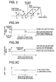
- Figure 3a is a chart showing main injection timing before and after performing the exhaust gas temperature rise control;
- Figure 3b is a chart showing the main injection amount before and after performing the exhaust gas temperature rise control;
- Figure 3c is a chart showing a crank shaft torque output of the engine before and after performing the exhaust gas temperature rise control;
- Figure 4 is a block diagram for determining the amount of fuel injection;
- Figure 5 is a diagram showing a relationship between the amount of the fuel injection and a torque output of the engine;
- Figure 6 is a block diagram showing another embodiment for determining fuel injection amount.
-
- Referring to Figure 1, an embodiment of a fuel injection control device will be described.
- The internal combustion engine E which employs a fuel injection control device of the embodiment is a 6-cylinder diesel engine equipped with a common rail fuel injection device.
- The fuel injection control device of this embodiment includes a
supply pump 5 for supplying fuel from a fuel tank (not illustrated) to a common rail 7, and multiple fuel injectors 6 which are connected to the common-rail 7 for injecting fuel into a combustion chamber of each engine E cylinder. - The
supply pump 5 is a pressure regulation pump which can adjust delivery pressure, and this delivery pressure is controlled by a controller (control means) 12. - A
pressure sensor 11 is provided in the common rail 7, the fuel pressure in the common-rail 7 is detected by thepressure sensor 11, and the detected value is input into thecontroller 12. - Each fuel injector 6 is connected with the
controller 12 and also controlled (operated) by a driving signal transmitted from thecontroller 12. A plurality of detection means such as anengine rotation sensor 16 for detecting the rotational speed of the engine E and an acceleratoropening degree sensor 17 for detecting the accelerator opening degree (engine load) of a vehicle are connected to thecontroller 12. The detection values obtained by the detection means 16 and 17 are inputted into thecontroller 12. Thecontroller 12 determines the amount of the basic fuel injection and basic fuel injection timing from a basic fuel injection map inputted beforehand based on the actual engine rotational speed detected by theengine rotation sensor 16 and the actual accelerator opening degree detected by the acceleratoropening degree sensor 17. Thecontroller 12 normally outputs the driving signal to each fuel injector 6 according to the amount of the basic fuel injection and the basic fuel injection timing. - Exhaust ports of all the cylinders in engine E are connected to an
exhaust pipe 24 through anexhaust manifold 23. Also, anexhaust purification device 30 for purifying exhaust gas is provided on theexhaust pipe 24. Theexhaust purification device 30 of this embodiment is known as so-called DPF having acasing 31 connected to the collectingexhaust pipe 24 and acatalyst filter 32 disposed in thecasing 31 for collecting PM in exhaust gas in order to burn (oxidize) and remove the PM. For example, catalyst such as zeolite can be applied onto a monolith honeycomb filter of a wall flow type made from ceramics or a fiber type filter made from ceramics or metal, etc, and these filters can be employed as thecatalyst filter 32. - When the exhaust gas passes through the inside of the
exhaust purification device 30, the PM in the exhaust gas is collected by the catalyst filer and the collected PM is oxidized and removed through the catalytic action. - The
exhaust emission control 30 has a sensor (exhaust gas temperature detection means) 34 for detecting the temperature of the exhaust gas which passes through theexhaust purification device 30, and the detected amount (value) from thesensor 34 is transmitted to thecontroller 12. - The intake pipe of engine E is omitted in Figure 1.
- As described in the section of "the description of the related art", the
exhaust purification device 30 using catalytic action does not provide sufficient exhaust gas purification unless the temperature of the exhaust gas which passes the exhaust purification device 30 (hereinafter referred to as exhaust gas temperature) is at or above the activation temperature (for example, 250 degrees C) of the catalyst. When the exhaust gas temperature detected by thesensor 34 is lower than the temperature required for catalyst action, the fuel injection timing is retarded from the basic fuel-injection timing in order to raise the exhaust gas temperature. The present invention increases the amount of the fuel injection compared to the amount of the basic fuel injection in order to compensate for the decrease of the torque output of the engine E caused by the retarded fuel injection timing when the exhaust gas temperature rise control is performed. - Hereafter, this point will be described in reference to Figure 2 and Figure 3.
- Figure 2 is a diagram showing the time and the amount of fuel injection. Figure 2 shows an example which performs dual injections including a preceding injection performed prior to the main injection and the main injection in one cycle.
- Figure 3a shows the timing of the main injection before and after performing the exhaust gas temperature rise control, Figure 3b shows the amount of the main fuel injection before and after performing the exhaust-gas temperature rise control, and Figure 3c shows the torque output of the engine E before and after performing the exhaust gas temperature rise control.
- When the exhaust gas temperature detected by the
sensor 34 is at or above the catalytic activation temperature required by thecatalyst filter 32 provided in theexhaust purification device 30, thecontroller 12 determines basic fuel injection timing and the basic amount of fuel injected at both the preceding and main fuel injection from the basic fuel injection map, and then transmits driving signals to fuel injectors 6. Therefore, the fuel injection timing Tp and the amount of fuel injection Qp (equivalent to the triangle area shown in Figure 2) of the preceding fuel injection supplied by fuel injectors 6, and fuel injection timing Tm and the amount of the fuel injection Qm of the main fuel injection, are respectively equivalent to the basic fuel injection timing and the basic fuel injection amount. - On the other hand, when the exhaust gas temperature is relatively low, such as when the engine E has just started or when the vehicle is driven with a light load, and the exhaust gas temperature detected by the
sensor 34 is lower than the activation temperature of the catalyst in thecatalyst filter 32 of theexhaust purification device 30, thecontroller 12 performs the exhaust gas temperature rise control. That is, while determining the basic fuel injection timing of the main fuel injection and the preceding fuel injection in accordance with the basic fuel injection map based on the actual engine rotational speed detected by theengine rotation sensor 16 and the actual accelerator opening degree detected by theaccelerator opening sensor 17, the retardation period of the fuel injection timing of the main injection and the preceding fuel injection is also determined in accordance with retardation period map which will be described later. The retarded fuel injection timing for the preceding fuel injection and the main fuel injection are determined by adding the retardation amount to the basic fuel injection timing. Moreover, the increased amount of the fuel injection of the main fuel injection and the preceding fuel injection is determined in reference to the increased amount of the fuel injection map which will be described later. Although more will be explained in detail, the increased amounts of the fuel injection of the main fuel injection and the preceding fuel injection determined by reference to the increased fuel injection amount map are larger than the amount of the basic fuel injection determined by reference to the basic fuel injection map under the same engine rotational speed and the accelerator opening degree. Thecontroller 12 then outputs a driving signal to each fuel injector 6 based on the retarded fuel injection timing and the increased amount of the fuel injection. - Accordingly, the fuel injection timing Tp' of the preceding fuel injection and fuel-injection timing Tm' of the main fuel injection supplied by the fuel injector 6 are respectively retarded from the basic fuel injection timing of preceding fuel injection and the main fuel injection, and also the amount of the fuel injection Qp' of the preceding fuel injection and the amount of the main fuel injection Qm' are respectively increased compared to the basic amount of the fuel injection of the preceding fuel injection and the main fuel injection.
- In addition, an example in which both preceding and main fuel injection timing are retarded from the basic fuel injection timing, but the amounts of the fuel injections are the same as the amounts of the basic fuel injection, is shown by the broken line in Figure 2.
- Thus, the fuel injection control device of the present invention increases the amount of the fuel injection in order to compensate the drop of torque output of the engine E caused by the retarded fuel injection timing. As a result, as shown in Figure 3c, substantially the same torque output is obtained before and after performing the exhaust gas temperature rise control. Therefore, there is no possibility of causing a driver to feel any driving discomfort.
- Next, the determination method of the retardation period of the fuel injection timing when the exhaust gas temperature rise control is performed will be described.
- First, appropriate retardation periods given to be to various basic fuel injection timing are prepared by experiments and tests beforehand based on various rotational speeds and the loads (mainly determined by an accelerator opening degrees) of the engine E, and these retardation periods are inputted into the
controller 12 in the form of an retardation period map beforehand. When the exhaust gas temperature rise control is performed, the retardation period is determined by the retardation period map from the actual engine rotational speed detected by the enginerotational sensor 16 and the actual accelerator opening degree detected by the acceleratoropening degree sensor 17. In the meantime, basic fuel injection is determined by the basic fuel injection timing map. Then, the fuel injection timing is determined by adding the retardation period to the basic fuel injection timing. - Next, the method of determining the correction amount of the fuel injection accompanied by retarding the fuel injection timing will be explained.
- Appropriately increased amounts of the fuel injection which are greater than the corresponding basic amounts of the fuel injection for various the rotational speeds and the loads of the engine E are obtained from experiment results, and the increased amounts of the fuel injection are inputted into the
controller 12 in the form of an increased fuel injection map beforehand. When the exhaust gas temperature rise control is performed, the increased amount of the fuel injection is determined by the increased fuel injection map based on the actual engine rotational speed detected by the enginerotational sensor 16 and the actual accelerator opening degree detected by the engine acceleratoropening degree sensor 17. - The block diagram for determining the amount of the fuel injection is shown in Figure 4.
- As shown in Figure 4, the basic amount of the fuel injection Qbase is determined by the basic fuel injection map M1 based on the engine rotational speed ENGrpm inputted from the
engine rotation sensor 16 and engine load (accelerator opening degree) ENGload inputted from the acceleratoropening degree sensor 17. Likewise, the increased amount of the fuel injection Qgain is determined by the increased fuel injection map M2 based on the engine rotational speed ENGrpm and engine load ENGload. When the exhaust gas temperature rise control mode (DPF Mode) is OFF, a switch S is connected to 0, and the basic amount of the fuel injection Qbase is used as the final fuel injection amount Qfinal which is outputted from thecontroller 12 to a fuel injector 6 as a final value. On the other hand, when the exhaust gas temperature rise control mode (DPF Mode) is ON, the switch S is switched to 1, and the increased amount of the fuel injection Qgain is determined as the final amount of fuel injection Qfinal. - It should be remembered here that the increased amount of the fuel injection is set to a value that does not cause the torque output fluctuation in the engine E before and after performing the exhaust gas temperature rise control.
- An example will be described in reference to Figure 5. In Figure 5, the horizontal axis shows a total amount of the fuel injection obtained by adding the amount of the main fuel injection to the amount of the preceding fuel injection, and the vertical axis shows the torque output of the crankshaft of the engine E. The line A shows the torque output of when the fuel injection is carried out at the normal fuel injection timing (the basic fuel injection timing), and the line B shows the torque output of when the fuel injection timing is retarded for a predetermined period from the basic fuel injection timing.
- It is supposed that a vehicle is in a condition C in which the exhaust gas temperature rise control (retardation of the fuel injection timing) is not performed. Under the condition, the amount of the fuel injection is Q1, and the torque output of the engine E is P1. When fuel injection timing is retarded in order to raise the exhaust gas temperature, the amount of the fuel injection is increased up to the point Q2 where the torque output obtained is equal to the torque output P1 of the normal fuel injection timing. That is, the added amount of fuel is obtained from the equation of Q2-Q1 (subtracting Q1 from Q2). By means of this, the occurrence of the torque fluctuation caused before and after performing exhaust gas temperature rise control can be avoided. The values of the increased amount of the fuel injection Qgain with which a torque output fluctuation is not generated when exhaust gas temperature rise control is performed, are prepared by testing beforehand under various operational conditions, and the increased fuel injection map M2 as shown in Figure 4 is prepared.
- The present invention is not only limited to the above-described embodiments and examples, and various changes and modifications may be made without departing from the spirit and scope of the invention.
- For example, the amount of the fuel injection may be determined with reference to the diagram as shown in Figure 6. In this embodiment, the correction amount map M3 which stores the appropriate correction amount Qcorrect determined based on the basic amount of the fuel injection Qbase and the engine rotational speed ENGrpm is prepared. The
controller 12 determines the amount of the basic fuel injection Qbase from the basic fuel-injection map M1 basicd on the engine rotational speed ENGrpm inputted from theengine rotation sensor 16, and engine load ENGload inputted from theaccelerator opening sensor 17, and determines the correction amount Qcorrect from the correction amount map M3 based on the basic amount of the fuel injection Qbase and engine rotational speed ENGrpm. When the exhaust gas temperature rise control mode (DPF Mode) is OFF, the switch S is connected to 0, and the basic amount of the fuel injection Qbase is determined as the final amount of the fuel injection Qfinal. On the other hand, when the exhaust gas temperature rise control mode (DPF Mode) is ON, the switch S is switched to 1, and the sum of the correction amount Qcorrect and the basic amount of the fuel injection Qbase (equivalent to the increased amount of the fuel injection Qgain in the embodiment of Figure 4) is determined as the final amount of the fuel injection Qfinal. It should be noted that the correction amount Qcorrect may be adjusted with reference to water temperature, intake air temperature, atmospheric pressure, etc. - Although the retardation period of the fuel injection timing is determined based on the engine rotational speed and the engine load in the foregoing description, it may be determined based on the difference between the actual exhaust gas temperature detected by the
sensor 34 and the catalyst activation temperature of theexhaust purification device 30. - Also, in the embodiment shown in Figure 2, the preceding fuel injection timing slower and main fuel injection timing are retarded and the preceding fuel injection amount and the main fuel injection amount are increased. However, the present invention is not limited in this regard. Setting the timing slower and correcting the injection amount only regarding the main fuel injection may be performed. Moreover, the fuel injection system of the present invention is not limited to a duel injection type, but can be applied to a single injection type which performs only a main fuel injection and a multi-injection type which performs more than one auxiliary fuel injection.
- Use of the
sensor 34 is not dispensable to detect the temperature of the exhaust gas which passes through theexhaust purification device 30. For instance, it is possible to calculate the temperature from a rotational speed, load condition, etc. of engine E. - Furthermore, the exhaust purification device is not limited to the above mentioned DPF type. Any types for exhaust purification device can be employed as long as it utilizes the catalytic to oxidize and remove NOx.
- In summary, the present invention displays an excellent effects by which the exhaust gas temperature can be raised in order to maintain the purification of the exhaust purification device and a fluctuation of torque output does not occur when the exhaust gas temperature is raised.
Claims (3)
- A fuel injection control device of an internal combustion engine comprising:an exhaust purification device located at an exhaust passage of an internal combustion engine for purifying an exhaust gas by catalytic action;exhaust gas temperature determination means for detecting or computing temperature of the exhaust gas passing through the exhaust purification device;determining means for determining an amount and a timing of basic fuel injection based on operational status such as a load and a rotational speed of the internal combustion engine; andcontrol means for controlling an amount and a timing of a fuel injection by a fuel injector of the internal combustion engine, wherein the control means controls the amount and the timing of the fuel injection to make them respectively equal to the amount of the basic fuel injection and the timing of the basic fuel injection timing when the detected or computed exhaust gas temperature is at or above a catalytic activation temperature of the exhaust purification device, and the control means raises the exhaust gas temperature by retarding the timing of the fuel injection timing from the timing of the basic fuel injection, and also increases the amount of the fuel injection from the amount of the basic fuel injection in order to compensate for a drop in a torque output of the internal combustion engine which is caused by retarding the timing of the fuel injection when the detected or computed exhaust gas temperature is lower than the catalytic activation temperature of the exhaust purification device.
- A fuel injection control device according to claim 1, characterized in that the control means determines retardation period from the timing of the basic fuel injection based on the load and the rotational speed of the internal combustion engine and determines the increased amount of the fuel injection based on the load and the rotational speed of the internal combustion engine.
- A fuel injection control device according to claim 2, characterized in that a relationship between the retardation period and the load and the rotational speed of the internal combustion engine and the relationship between fuel injection and the load and the rotational speed of the internal combustion engine are stored into the control means in the form of maps, and the control means controls the timing of the fuel injection and the increased amount of fuel injection according to the maps.
Applications Claiming Priority (2)
| Application Number | Priority Date | Filing Date | Title |
|---|---|---|---|
| JP2002345644A JP2004176657A (en) | 2002-11-28 | 2002-11-28 | Fuel injection control device |
| JP2002345644 | 2002-11-28 |
Publications (3)
| Publication Number | Publication Date |
|---|---|
| EP1424482A2 true EP1424482A2 (en) | 2004-06-02 |
| EP1424482A3 EP1424482A3 (en) | 2005-06-29 |
| EP1424482B1 EP1424482B1 (en) | 2011-01-19 |
Family
ID=32290468
Family Applications (1)
| Application Number | Title | Priority Date | Filing Date |
|---|---|---|---|
| EP03026837A Expired - Lifetime EP1424482B1 (en) | 2002-11-28 | 2003-11-20 | Fuel injection control device |
Country Status (5)
| Country | Link |
|---|---|
| US (1) | US7021045B2 (en) |
| EP (1) | EP1424482B1 (en) |
| JP (1) | JP2004176657A (en) |
| AT (1) | ATE496209T1 (en) |
| DE (1) | DE60335776D1 (en) |
Cited By (2)
| Publication number | Priority date | Publication date | Assignee | Title |
|---|---|---|---|---|
| EP3428416A4 (en) * | 2016-03-07 | 2019-03-20 | Isuzu Motors Limited | Exhaust purification system and control method |
| US11143127B2 (en) * | 2018-08-07 | 2021-10-12 | Toyota Jidosha Kabushiki Kaisha | Vehicle controller and control method performing fuel feeding process while stopping combustion for filter regeneration |
Families Citing this family (9)
| Publication number | Priority date | Publication date | Assignee | Title |
|---|---|---|---|---|
| JP3880296B2 (en) * | 2000-08-02 | 2007-02-14 | 株式会社日立製作所 | Engine control device |
| US7365033B1 (en) | 2003-10-02 | 2008-04-29 | Ventex, Inc. | Open flame resistant articles |
| US7181908B2 (en) * | 2004-03-30 | 2007-02-27 | General Motors Corporation | Torque compensation method for controlling a direct-injection engine during regeneration of a lean NOx trap |
| US7343735B2 (en) * | 2005-05-02 | 2008-03-18 | Cummins, Inc. | Apparatus and method for regenerating an exhaust gas aftertreatment component of an internal combustion engine |
| JP2007285139A (en) * | 2006-04-13 | 2007-11-01 | Denso Corp | Control unit for diesel engine |
| DE102006027591B4 (en) * | 2006-06-14 | 2012-03-08 | Caterpillar Motoren Gmbh & Co. Kg | Method for controlling an internal combustion engine |
| JP4937877B2 (en) * | 2007-10-12 | 2012-05-23 | 富士重工業株式会社 | Diesel engine control device |
| US9353696B2 (en) * | 2012-05-24 | 2016-05-31 | Cummins Ip, Inc. | Combustion controller for internal combustion engine |
| US10801433B2 (en) * | 2018-04-24 | 2020-10-13 | GM Global Technology Operations LLC | Systems and methods for determining irregular fuel requests during engine idle conditions |
Citations (5)
| Publication number | Priority date | Publication date | Assignee | Title |
|---|---|---|---|---|
| US4719751A (en) * | 1984-03-31 | 1988-01-19 | Mitsubishi Jidosha Kogyo K.K. | Diesel particulate oxidizer regeneration system |
| US5050551A (en) * | 1989-11-22 | 1991-09-24 | Fuji Jukogyo Kabushiki Kaisha | System for controlling ignition timing and fuel injection timing of a two-cycle engine |
| WO2001027455A1 (en) * | 1999-10-08 | 2001-04-19 | Renault | Fuel injection method for a combustion engine |
| WO2002066813A1 (en) * | 2001-02-20 | 2002-08-29 | Isuzu Motors Limited | Fuel injection control method for diesel engine and regenerative control method for exhaust gas after treatment device |
| EP1418324A2 (en) * | 2002-11-07 | 2004-05-12 | Renault s.a.s. | Method and apparatus for the regeneration of a particle filter |
Family Cites Families (9)
| Publication number | Priority date | Publication date | Assignee | Title |
|---|---|---|---|---|
| JPH1081992A (en) | 1996-09-02 | 1998-03-31 | Dainippon Printing Co Ltd | Partial plating device of lead frame and partial plating method |
| JPH10252543A (en) | 1997-03-12 | 1998-09-22 | Denso Corp | Exhaust purifying device for internal combustion engine |
| JP4039500B2 (en) | 1998-02-23 | 2008-01-30 | 株式会社デンソー | Exhaust gas purification device for internal combustion engine |
| JP3325230B2 (en) * | 1998-08-03 | 2002-09-17 | マツダ株式会社 | Method and apparatus for warming up a catalyst in a direct injection engine |
| JP3607980B2 (en) * | 1999-12-16 | 2005-01-05 | トヨタ自動車株式会社 | Internal combustion engine |
| JP2001289093A (en) * | 2000-03-31 | 2001-10-19 | Hitachi Ltd | Exhaust control device for cylinder fuel injection engine |
| JP4389372B2 (en) * | 2000-09-29 | 2009-12-24 | マツダ株式会社 | Engine fuel control device |
| JP3963088B2 (en) * | 2001-09-06 | 2007-08-22 | マツダ株式会社 | Control device for spark ignition direct injection engine |
| JP4092464B2 (en) * | 2002-06-28 | 2008-05-28 | 日産自動車株式会社 | Exhaust purification device |
-
2002
- 2002-11-28 JP JP2002345644A patent/JP2004176657A/en active Pending
-
2003
- 2003-11-20 AT AT03026837T patent/ATE496209T1/en not_active IP Right Cessation
- 2003-11-20 EP EP03026837A patent/EP1424482B1/en not_active Expired - Lifetime
- 2003-11-20 DE DE60335776T patent/DE60335776D1/en not_active Expired - Lifetime
- 2003-11-25 US US10/721,133 patent/US7021045B2/en not_active Expired - Fee Related
Patent Citations (5)
| Publication number | Priority date | Publication date | Assignee | Title |
|---|---|---|---|---|
| US4719751A (en) * | 1984-03-31 | 1988-01-19 | Mitsubishi Jidosha Kogyo K.K. | Diesel particulate oxidizer regeneration system |
| US5050551A (en) * | 1989-11-22 | 1991-09-24 | Fuji Jukogyo Kabushiki Kaisha | System for controlling ignition timing and fuel injection timing of a two-cycle engine |
| WO2001027455A1 (en) * | 1999-10-08 | 2001-04-19 | Renault | Fuel injection method for a combustion engine |
| WO2002066813A1 (en) * | 2001-02-20 | 2002-08-29 | Isuzu Motors Limited | Fuel injection control method for diesel engine and regenerative control method for exhaust gas after treatment device |
| EP1418324A2 (en) * | 2002-11-07 | 2004-05-12 | Renault s.a.s. | Method and apparatus for the regeneration of a particle filter |
Cited By (3)
| Publication number | Priority date | Publication date | Assignee | Title |
|---|---|---|---|---|
| EP3428416A4 (en) * | 2016-03-07 | 2019-03-20 | Isuzu Motors Limited | Exhaust purification system and control method |
| US10711673B2 (en) | 2016-03-07 | 2020-07-14 | Isuzu Motors Limited | Exhaust purification system and control method |
| US11143127B2 (en) * | 2018-08-07 | 2021-10-12 | Toyota Jidosha Kabushiki Kaisha | Vehicle controller and control method performing fuel feeding process while stopping combustion for filter regeneration |
Also Published As
| Publication number | Publication date |
|---|---|
| EP1424482B1 (en) | 2011-01-19 |
| EP1424482A3 (en) | 2005-06-29 |
| US7021045B2 (en) | 2006-04-04 |
| US20040103647A1 (en) | 2004-06-03 |
| ATE496209T1 (en) | 2011-02-15 |
| JP2004176657A (en) | 2004-06-24 |
| DE60335776D1 (en) | 2011-03-03 |
Similar Documents
| Publication | Publication Date | Title |
|---|---|---|
| US7197867B2 (en) | Method for the simultaneous desulfation of a lean NOx trap and regeneration of a Diesel particulate filter | |
| US6959541B2 (en) | Fuel injection control system for internal combustion engine | |
| US20100132334A1 (en) | Method and device for monitoring the regeneration of a pollution-removal system | |
| US8261535B2 (en) | Enhanced post injection control system for diesel particulate filters | |
| US5826425A (en) | Method of automatically initiating regeneration of a particulate filter of a diesel engine with a rail injection system | |
| US6898508B2 (en) | Fuel injection control device | |
| US8833061B2 (en) | Method and device for regenerating a particle filter in a Y-exhaust gas system | |
| US7007462B2 (en) | Combustion control apparatus for internal combustion engine | |
| US6990801B2 (en) | Combustion control apparatus for internal combustion engine | |
| US9067160B2 (en) | Exhaust gas purification system | |
| US7021045B2 (en) | Fuel injection control device | |
| US7885757B2 (en) | Degradation determination apparatus and degradation determination system for oxygen concentration sensor | |
| EP1496234B1 (en) | Combustion control apparatus for internal combustion engine | |
| JP2005240755A (en) | Fuel injection control device of engine | |
| US20070012031A1 (en) | Fuel control for diesel engine having particulate filter | |
| US6170260B1 (en) | Exhaust emission control apparatus for combustion engine | |
| JP2003500596A (en) | Method and apparatus for controlling an internal combustion engine | |
| EP1496235A2 (en) | Combustion control apparatus for internal combustion engine | |
| US8943810B2 (en) | Exhaust gas purification system for an internal combustion engine | |
| EP2578824B1 (en) | System for purifying exhaust gas in upland area | |
| WO2022264565A1 (en) | Control device for catalyst temperature raising system | |
| WO2023223504A1 (en) | Device and method for controlling oxygen storage amount in three-way catalyst | |
| JP4063743B2 (en) | Fuel injection timing control device for internal combustion engine | |
| JP6881230B2 (en) | Vehicle control device | |
| JP2010190119A (en) | Combustion control device for diesel engine |
Legal Events
| Date | Code | Title | Description |
|---|---|---|---|
| PUAI | Public reference made under article 153(3) epc to a published international application that has entered the european phase |
Free format text: ORIGINAL CODE: 0009012 |
|
| AK | Designated contracting states |
Kind code of ref document: A2 Designated state(s): AT BE BG CH CY CZ DE DK EE ES FI FR GB GR HU IE IT LI LU MC NL PT RO SE SI SK TR |
|
| AX | Request for extension of the european patent |
Extension state: AL LT LV MK |
|
| PUAL | Search report despatched |
Free format text: ORIGINAL CODE: 0009013 |
|
| AK | Designated contracting states |
Kind code of ref document: A3 Designated state(s): AT BE BG CH CY CZ DE DK EE ES FI FR GB GR HU IE IT LI LU MC NL PT RO SE SI SK TR |
|
| AX | Request for extension of the european patent |
Extension state: AL LT LV MK |
|
| 17P | Request for examination filed |
Effective date: 20051219 |
|
| AKX | Designation fees paid |
Designated state(s): AT BE BG CH CY CZ DE DK EE ES FI FR GB GR HU IE IT LI LU MC NL PT RO SE SI SK TR |
|
| 17Q | First examination report despatched |
Effective date: 20060927 |
|
| GRAP | Despatch of communication of intention to grant a patent |
Free format text: ORIGINAL CODE: EPIDOSNIGR1 |
|
| GRAS | Grant fee paid |
Free format text: ORIGINAL CODE: EPIDOSNIGR3 |
|
| GRAA | (expected) grant |
Free format text: ORIGINAL CODE: 0009210 |
|
| AK | Designated contracting states |
Kind code of ref document: B1 Designated state(s): AT BE BG CH CY CZ DE DK EE ES FI FR GB GR HU IE IT LI LU MC NL PT RO SE SI SK TR |
|
| REG | Reference to a national code |
Ref country code: GB Ref legal event code: FG4D |
|
| REG | Reference to a national code |
Ref country code: CH Ref legal event code: EP |
|
| REG | Reference to a national code |
Ref country code: IE Ref legal event code: FG4D |
|
| REF | Corresponds to: |
Ref document number: 60335776 Country of ref document: DE Date of ref document: 20110303 Kind code of ref document: P |
|
| REG | Reference to a national code |
Ref country code: DE Ref legal event code: R096 Ref document number: 60335776 Country of ref document: DE Effective date: 20110303 |
|
| REG | Reference to a national code |
Ref country code: NL Ref legal event code: VDEP Effective date: 20110119 |
|
| PG25 | Lapsed in a contracting state [announced via postgrant information from national office to epo] |
Ref country code: ES Free format text: LAPSE BECAUSE OF FAILURE TO SUBMIT A TRANSLATION OF THE DESCRIPTION OR TO PAY THE FEE WITHIN THE PRESCRIBED TIME-LIMIT Effective date: 20110430 Ref country code: PT Free format text: LAPSE BECAUSE OF FAILURE TO SUBMIT A TRANSLATION OF THE DESCRIPTION OR TO PAY THE FEE WITHIN THE PRESCRIBED TIME-LIMIT Effective date: 20110519 Ref country code: GR Free format text: LAPSE BECAUSE OF FAILURE TO SUBMIT A TRANSLATION OF THE DESCRIPTION OR TO PAY THE FEE WITHIN THE PRESCRIBED TIME-LIMIT Effective date: 20110420 Ref country code: SE Free format text: LAPSE BECAUSE OF FAILURE TO SUBMIT A TRANSLATION OF THE DESCRIPTION OR TO PAY THE FEE WITHIN THE PRESCRIBED TIME-LIMIT Effective date: 20110119 |
|
| PG25 | Lapsed in a contracting state [announced via postgrant information from national office to epo] |
Ref country code: BG Free format text: LAPSE BECAUSE OF FAILURE TO SUBMIT A TRANSLATION OF THE DESCRIPTION OR TO PAY THE FEE WITHIN THE PRESCRIBED TIME-LIMIT Effective date: 20110419 Ref country code: AT Free format text: LAPSE BECAUSE OF FAILURE TO SUBMIT A TRANSLATION OF THE DESCRIPTION OR TO PAY THE FEE WITHIN THE PRESCRIBED TIME-LIMIT Effective date: 20110119 Ref country code: BE Free format text: LAPSE BECAUSE OF FAILURE TO SUBMIT A TRANSLATION OF THE DESCRIPTION OR TO PAY THE FEE WITHIN THE PRESCRIBED TIME-LIMIT Effective date: 20110119 Ref country code: CY Free format text: LAPSE BECAUSE OF FAILURE TO SUBMIT A TRANSLATION OF THE DESCRIPTION OR TO PAY THE FEE WITHIN THE PRESCRIBED TIME-LIMIT Effective date: 20110119 Ref country code: NL Free format text: LAPSE BECAUSE OF FAILURE TO SUBMIT A TRANSLATION OF THE DESCRIPTION OR TO PAY THE FEE WITHIN THE PRESCRIBED TIME-LIMIT Effective date: 20110119 Ref country code: FI Free format text: LAPSE BECAUSE OF FAILURE TO SUBMIT A TRANSLATION OF THE DESCRIPTION OR TO PAY THE FEE WITHIN THE PRESCRIBED TIME-LIMIT Effective date: 20110119 Ref country code: SI Free format text: LAPSE BECAUSE OF FAILURE TO SUBMIT A TRANSLATION OF THE DESCRIPTION OR TO PAY THE FEE WITHIN THE PRESCRIBED TIME-LIMIT Effective date: 20110119 |
|
| PG25 | Lapsed in a contracting state [announced via postgrant information from national office to epo] |
Ref country code: EE Free format text: LAPSE BECAUSE OF FAILURE TO SUBMIT A TRANSLATION OF THE DESCRIPTION OR TO PAY THE FEE WITHIN THE PRESCRIBED TIME-LIMIT Effective date: 20110119 Ref country code: DK Free format text: LAPSE BECAUSE OF FAILURE TO SUBMIT A TRANSLATION OF THE DESCRIPTION OR TO PAY THE FEE WITHIN THE PRESCRIBED TIME-LIMIT Effective date: 20110119 |
|
| PLBE | No opposition filed within time limit |
Free format text: ORIGINAL CODE: 0009261 |
|
| STAA | Information on the status of an ep patent application or granted ep patent |
Free format text: STATUS: NO OPPOSITION FILED WITHIN TIME LIMIT |
|
| PG25 | Lapsed in a contracting state [announced via postgrant information from national office to epo] |
Ref country code: RO Free format text: LAPSE BECAUSE OF FAILURE TO SUBMIT A TRANSLATION OF THE DESCRIPTION OR TO PAY THE FEE WITHIN THE PRESCRIBED TIME-LIMIT Effective date: 20110119 Ref country code: CZ Free format text: LAPSE BECAUSE OF FAILURE TO SUBMIT A TRANSLATION OF THE DESCRIPTION OR TO PAY THE FEE WITHIN THE PRESCRIBED TIME-LIMIT Effective date: 20110119 Ref country code: SK Free format text: LAPSE BECAUSE OF FAILURE TO SUBMIT A TRANSLATION OF THE DESCRIPTION OR TO PAY THE FEE WITHIN THE PRESCRIBED TIME-LIMIT Effective date: 20110119 |
|
| 26N | No opposition filed |
Effective date: 20111020 |
|
| PG25 | Lapsed in a contracting state [announced via postgrant information from national office to epo] |
Ref country code: IT Free format text: LAPSE BECAUSE OF FAILURE TO SUBMIT A TRANSLATION OF THE DESCRIPTION OR TO PAY THE FEE WITHIN THE PRESCRIBED TIME-LIMIT Effective date: 20110119 |
|
| REG | Reference to a national code |
Ref country code: DE Ref legal event code: R097 Ref document number: 60335776 Country of ref document: DE Effective date: 20111020 |
|
| PG25 | Lapsed in a contracting state [announced via postgrant information from national office to epo] |
Ref country code: MC Free format text: LAPSE BECAUSE OF NON-PAYMENT OF DUE FEES Effective date: 20111130 |
|
| REG | Reference to a national code |
Ref country code: CH Ref legal event code: PL |
|
| PG25 | Lapsed in a contracting state [announced via postgrant information from national office to epo] |
Ref country code: LI Free format text: LAPSE BECAUSE OF NON-PAYMENT OF DUE FEES Effective date: 20111130 Ref country code: CH Free format text: LAPSE BECAUSE OF NON-PAYMENT OF DUE FEES Effective date: 20111130 |
|
| REG | Reference to a national code |
Ref country code: IE Ref legal event code: MM4A |
|
| REG | Reference to a national code |
Ref country code: AT Ref legal event code: MK05 Ref document number: 496209 Country of ref document: AT Kind code of ref document: T Effective date: 20110119 |
|
| PG25 | Lapsed in a contracting state [announced via postgrant information from national office to epo] |
Ref country code: IE Free format text: LAPSE BECAUSE OF NON-PAYMENT OF DUE FEES Effective date: 20111120 |
|
| PGFP | Annual fee paid to national office [announced via postgrant information from national office to epo] |
Ref country code: FR Payment date: 20121130 Year of fee payment: 10 |
|
| PG25 | Lapsed in a contracting state [announced via postgrant information from national office to epo] |
Ref country code: LU Free format text: LAPSE BECAUSE OF NON-PAYMENT OF DUE FEES Effective date: 20111120 |
|
| PG25 | Lapsed in a contracting state [announced via postgrant information from national office to epo] |
Ref country code: TR Free format text: LAPSE BECAUSE OF FAILURE TO SUBMIT A TRANSLATION OF THE DESCRIPTION OR TO PAY THE FEE WITHIN THE PRESCRIBED TIME-LIMIT Effective date: 20110119 |
|
| PG25 | Lapsed in a contracting state [announced via postgrant information from national office to epo] |
Ref country code: HU Free format text: LAPSE BECAUSE OF FAILURE TO SUBMIT A TRANSLATION OF THE DESCRIPTION OR TO PAY THE FEE WITHIN THE PRESCRIBED TIME-LIMIT Effective date: 20110119 |
|
| REG | Reference to a national code |
Ref country code: FR Ref legal event code: ST Effective date: 20140731 |
|
| PG25 | Lapsed in a contracting state [announced via postgrant information from national office to epo] |
Ref country code: FR Free format text: LAPSE BECAUSE OF NON-PAYMENT OF DUE FEES Effective date: 20131202 |
|
| PGFP | Annual fee paid to national office [announced via postgrant information from national office to epo] |
Ref country code: GB Payment date: 20141119 Year of fee payment: 12 |
|
| REG | Reference to a national code |
Ref country code: DE Ref legal event code: R082 Ref document number: 60335776 Country of ref document: DE Representative=s name: SCHAUMBURG UND PARTNER PATENTANWAELTE MBB, DE Ref country code: DE Ref legal event code: R082 Ref document number: 60335776 Country of ref document: DE Representative=s name: SCHAUMBURG & PARTNER PATENTANWAELTE GBR, DE Ref country code: DE Ref legal event code: R082 Ref document number: 60335776 Country of ref document: DE Representative=s name: SCHAUMBURG & PARTNER PATENTANWAELTE MBB, DE |
|
| PGFP | Annual fee paid to national office [announced via postgrant information from national office to epo] |
Ref country code: DE Payment date: 20151118 Year of fee payment: 13 |
|
| GBPC | Gb: european patent ceased through non-payment of renewal fee |
Effective date: 20151120 |
|
| PG25 | Lapsed in a contracting state [announced via postgrant information from national office to epo] |
Ref country code: GB Free format text: LAPSE BECAUSE OF NON-PAYMENT OF DUE FEES Effective date: 20151120 |
|
| REG | Reference to a national code |
Ref country code: DE Ref legal event code: R119 Ref document number: 60335776 Country of ref document: DE |
|
| PG25 | Lapsed in a contracting state [announced via postgrant information from national office to epo] |
Ref country code: DE Free format text: LAPSE BECAUSE OF NON-PAYMENT OF DUE FEES Effective date: 20170601 |