JP4092464B2 - Exhaust purification device - Google Patents
Exhaust purification device Download PDFInfo
- Publication number
- JP4092464B2 JP4092464B2 JP2002189206A JP2002189206A JP4092464B2 JP 4092464 B2 JP4092464 B2 JP 4092464B2 JP 2002189206 A JP2002189206 A JP 2002189206A JP 2002189206 A JP2002189206 A JP 2002189206A JP 4092464 B2 JP4092464 B2 JP 4092464B2
- Authority
- JP
- Japan
- Prior art keywords
- oxygen concentration
- filter
- temperature
- period
- control period
- Prior art date
- Legal status (The legal status is an assumption and is not a legal conclusion. Google has not performed a legal analysis and makes no representation as to the accuracy of the status listed.)
- Expired - Fee Related
Links
Images


Classifications
-
- F—MECHANICAL ENGINEERING; LIGHTING; HEATING; WEAPONS; BLASTING
- F01—MACHINES OR ENGINES IN GENERAL; ENGINE PLANTS IN GENERAL; STEAM ENGINES
- F01N—GAS-FLOW SILENCERS OR EXHAUST APPARATUS FOR MACHINES OR ENGINES IN GENERAL; GAS-FLOW SILENCERS OR EXHAUST APPARATUS FOR INTERNAL COMBUSTION ENGINES
- F01N3/00—Exhaust or silencing apparatus having means for purifying, rendering innocuous, or otherwise treating exhaust
- F01N3/02—Exhaust or silencing apparatus having means for purifying, rendering innocuous, or otherwise treating exhaust for cooling, or for removing solid constituents of, exhaust
- F01N3/021—Exhaust or silencing apparatus having means for purifying, rendering innocuous, or otherwise treating exhaust for cooling, or for removing solid constituents of, exhaust by means of filters
- F01N3/023—Exhaust or silencing apparatus having means for purifying, rendering innocuous, or otherwise treating exhaust for cooling, or for removing solid constituents of, exhaust by means of filters using means for regenerating the filters, e.g. by burning trapped particles
-
- F—MECHANICAL ENGINEERING; LIGHTING; HEATING; WEAPONS; BLASTING
- F02—COMBUSTION ENGINES; HOT-GAS OR COMBUSTION-PRODUCT ENGINE PLANTS
- F02D—CONTROLLING COMBUSTION ENGINES
- F02D41/00—Electrical control of supply of combustible mixture or its constituents
- F02D41/02—Circuit arrangements for generating control signals
- F02D41/021—Introducing corrections for particular conditions exterior to the engine
- F02D41/0235—Introducing corrections for particular conditions exterior to the engine in relation with the state of the exhaust gas treating apparatus
- F02D41/024—Introducing corrections for particular conditions exterior to the engine in relation with the state of the exhaust gas treating apparatus to increase temperature of the exhaust gas treating apparatus
- F02D41/0245—Introducing corrections for particular conditions exterior to the engine in relation with the state of the exhaust gas treating apparatus to increase temperature of the exhaust gas treating apparatus by increasing temperature of the exhaust gas leaving the engine
-
- F—MECHANICAL ENGINEERING; LIGHTING; HEATING; WEAPONS; BLASTING
- F02—COMBUSTION ENGINES; HOT-GAS OR COMBUSTION-PRODUCT ENGINE PLANTS
- F02D—CONTROLLING COMBUSTION ENGINES
- F02D41/00—Electrical control of supply of combustible mixture or its constituents
- F02D41/02—Circuit arrangements for generating control signals
- F02D41/021—Introducing corrections for particular conditions exterior to the engine
- F02D41/0235—Introducing corrections for particular conditions exterior to the engine in relation with the state of the exhaust gas treating apparatus
- F02D41/024—Introducing corrections for particular conditions exterior to the engine in relation with the state of the exhaust gas treating apparatus to increase temperature of the exhaust gas treating apparatus
- F02D41/025—Introducing corrections for particular conditions exterior to the engine in relation with the state of the exhaust gas treating apparatus to increase temperature of the exhaust gas treating apparatus by changing the composition of the exhaust gas, e.g. for exothermic reaction on exhaust gas treating apparatus
-
- F—MECHANICAL ENGINEERING; LIGHTING; HEATING; WEAPONS; BLASTING
- F02—COMBUSTION ENGINES; HOT-GAS OR COMBUSTION-PRODUCT ENGINE PLANTS
- F02D—CONTROLLING COMBUSTION ENGINES
- F02D41/00—Electrical control of supply of combustible mixture or its constituents
- F02D41/02—Circuit arrangements for generating control signals
- F02D41/021—Introducing corrections for particular conditions exterior to the engine
- F02D41/0235—Introducing corrections for particular conditions exterior to the engine in relation with the state of the exhaust gas treating apparatus
- F02D41/027—Introducing corrections for particular conditions exterior to the engine in relation with the state of the exhaust gas treating apparatus to purge or regenerate the exhaust gas treating apparatus
- F02D41/029—Introducing corrections for particular conditions exterior to the engine in relation with the state of the exhaust gas treating apparatus to purge or regenerate the exhaust gas treating apparatus the exhaust gas treating apparatus being a particulate filter
-
- F—MECHANICAL ENGINEERING; LIGHTING; HEATING; WEAPONS; BLASTING
- F01—MACHINES OR ENGINES IN GENERAL; ENGINE PLANTS IN GENERAL; STEAM ENGINES
- F01N—GAS-FLOW SILENCERS OR EXHAUST APPARATUS FOR MACHINES OR ENGINES IN GENERAL; GAS-FLOW SILENCERS OR EXHAUST APPARATUS FOR INTERNAL COMBUSTION ENGINES
- F01N2560/00—Exhaust systems with means for detecting or measuring exhaust gas components or characteristics
- F01N2560/08—Exhaust systems with means for detecting or measuring exhaust gas components or characteristics the means being a pressure sensor
-
- F—MECHANICAL ENGINEERING; LIGHTING; HEATING; WEAPONS; BLASTING
- F02—COMBUSTION ENGINES; HOT-GAS OR COMBUSTION-PRODUCT ENGINE PLANTS
- F02B—INTERNAL-COMBUSTION PISTON ENGINES; COMBUSTION ENGINES IN GENERAL
- F02B37/00—Engines characterised by provision of pumps driven at least for part of the time by exhaust
- F02B37/12—Control of the pumps
- F02B37/22—Control of the pumps by varying cross-section of exhaust passages or air passages, e.g. by throttling turbine inlets or outlets or by varying effective number of guide conduits
-
- F—MECHANICAL ENGINEERING; LIGHTING; HEATING; WEAPONS; BLASTING
- F02—COMBUSTION ENGINES; HOT-GAS OR COMBUSTION-PRODUCT ENGINE PLANTS
- F02D—CONTROLLING COMBUSTION ENGINES
- F02D41/00—Electrical control of supply of combustible mixture or its constituents
- F02D41/02—Circuit arrangements for generating control signals
- F02D41/14—Introducing closed-loop corrections
- F02D41/1438—Introducing closed-loop corrections using means for determining characteristics of the combustion gases; Sensors therefor
- F02D41/1444—Introducing closed-loop corrections using means for determining characteristics of the combustion gases; Sensors therefor characterised by the characteristics of the combustion gases
- F02D41/1446—Introducing closed-loop corrections using means for determining characteristics of the combustion gases; Sensors therefor characterised by the characteristics of the combustion gases the characteristics being exhaust temperatures
-
- F—MECHANICAL ENGINEERING; LIGHTING; HEATING; WEAPONS; BLASTING
- F02—COMBUSTION ENGINES; HOT-GAS OR COMBUSTION-PRODUCT ENGINE PLANTS
- F02D—CONTROLLING COMBUSTION ENGINES
- F02D41/00—Electrical control of supply of combustible mixture or its constituents
- F02D41/02—Circuit arrangements for generating control signals
- F02D41/14—Introducing closed-loop corrections
- F02D41/1438—Introducing closed-loop corrections using means for determining characteristics of the combustion gases; Sensors therefor
- F02D41/1444—Introducing closed-loop corrections using means for determining characteristics of the combustion gases; Sensors therefor characterised by the characteristics of the combustion gases
- F02D41/1454—Introducing closed-loop corrections using means for determining characteristics of the combustion gases; Sensors therefor characterised by the characteristics of the combustion gases the characteristics being an oxygen content or concentration or the air-fuel ratio
-
- Y—GENERAL TAGGING OF NEW TECHNOLOGICAL DEVELOPMENTS; GENERAL TAGGING OF CROSS-SECTIONAL TECHNOLOGIES SPANNING OVER SEVERAL SECTIONS OF THE IPC; TECHNICAL SUBJECTS COVERED BY FORMER USPC CROSS-REFERENCE ART COLLECTIONS [XRACs] AND DIGESTS
- Y02—TECHNOLOGIES OR APPLICATIONS FOR MITIGATION OR ADAPTATION AGAINST CLIMATE CHANGE
- Y02T—CLIMATE CHANGE MITIGATION TECHNOLOGIES RELATED TO TRANSPORTATION
- Y02T10/00—Road transport of goods or passengers
- Y02T10/10—Internal combustion engine [ICE] based vehicles
- Y02T10/12—Improving ICE efficiencies
Description
【0001】
【発明の属する技術分野】
本発明は例えばディーゼルエンジンの排気パティキュレートを処理する排気浄化装置に関する。
【0002】
【従来の技術】
ディーゼルエンジンから排出される排気パティキュレートを処理するために、排気系にパティキュレートを捕集するフィルタを配置し、フィルタに所定量のパティキュレートが堆積したとき、フィルタ温度を上昇させてフィルタに堆積しているパテキュレートを燃焼処理する、いわゆるフィルタの再生処理を行うものが各種提案されている(特開2000−179326号公報参照)。
【0003】
【発明が解決しようとする課題】
ところで、フィルタの再生処理には概ね次の3つの要求を共に満たさなければならない。
【0004】
(1)再生処理の開始に際しては、フィルタのベッド温度を、フィルタに堆積しているパティキュレートの自着火温度まで速やかに上昇させる必要がある。フィルタのベッドを昇温させるため例えばポスト噴射や燃料噴射時期の遅角が行われるが、速やかな昇温が要求されるのは、フィルタのベッド昇温期間が長引けばそれだけ燃費が悪化するからである。
【0005】
(2)フィルタのベッド温度がパティキュレートの自着火温度に達してパティキュレートが燃焼する段階になると、フィルタのベッド温度が許容最高温度を超えないようにパティキュレートの燃焼速度を抑制する必要がある。これは、パティキュレートの燃焼速度が速いとフィルタに堆積している大量のパティキュレートが急激に燃焼してフィルタのベッド温度が許容最高温度を超え、これによってフィルタに熱劣化が生じて耐久性が低下しかねないからである。
【0006】
(3)再生処理の終了間近に際しては、フィルタにパティキュレートの燃え残りが生じないようにする必要がある。これはフィルタに燃え残りが生じると、次のような問題点が生じるからである。
【0007】
▲1▼フィルタの圧力損失が完全になくならないので、燃費が悪化する。
【0008】
▲2▼燃え残り部分にパティキュレートが堆積すると堆積分布のアンバランスが生じ、次の再生処理時にその部分の急激燃焼によりフィルタの耐久性が低下する。
【0009】
しかしながら、上記従来装置は再生処理の全期間に亘って排気温度が一定の目標温度になるように制御するものにすぎず、再生処理の開始から終了までを1つの温度で制御している。そのため、上記(1)の再生処理の開始に際しての、上記(2)のパティキュレートが燃焼する段階での、上記(3)の再生処理終了間近での各要求をともに満たすことができない。
【0010】
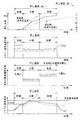
例えば、従来装置において目標温度を高く設定すると、フィルタのベッド温度の上昇に要する期間は短縮できるものの、パティキュレートが燃焼を進行する段階でのフィルタのベッド温度が高くなりすぎてフィルタのベッド温度が許容最高温度を超えてしまいかねない(図22の第1段目、第2段目、第4段目の一点鎖線参照)。かといって目標温度を低く設定したのでは再生処理の終了までの期間が長引いてしまう(図22の第1段目、第2段目、第4段目の破線参照)。
【0011】
そこで本発明は、上記3つの要求に合わせて再生処理期間を前期、中期、後期の3つに分割し、分割した各段階に対して最適な制御を行うこととした。すなわち、
再生処理前期:フィルタのベッド温度をパティキュレートの自着火温度へと急速に上昇させるため、目標温度を高く設定する。
【0012】
再生処理中期:目標温度は再生処理前期より低く設定し、かつパティキュレートの燃焼速度を抑制するため排気中の目標酸素濃度を低濃度に設定した第1酸素濃度制御を行う。
【0013】
再生処理後期:目標温度は再生処理前期より低く設定し、かつフィルタにパティキュレートが燃え残ることがないように、排気中の目標酸素濃度を高濃度に設定した第2酸素濃度制御を行う。
【0014】
このように3段階の処理によって再生処理の上記3つの要求を共に満たす装置を提供することを目的とする。
【0015】
【課題を解決するための手段】
請求項1に記載の発明は、排気通路にパティキュレートを捕集するフィルタを備え、フィルタの再生時期になるとフィルタの再生処理を行うエンジンの排気浄化装置において、フィルタの再生処理が急速昇温制御とこの急速昇温制御の経過後の酸素濃度制御とを含み、酸素濃度制御期間のフィルタ入口温度の目標値は一定であり、急速昇温制御期間のフィルタ入口温度の目標値は酸素濃度制御期間のフィルタ入口温度の目標値よりも高く、かつ酸素濃度制御期間はパティキュレートの燃焼速度を抑制するため排気中の目標酸素濃度を低濃度に設定した第1酸素濃度制御を行う第1酸素濃度制御期間と、第1酸素濃度制御期間の経過後にフィルタにパティキュレートが燃え残ることがないように排気中の目標酸素濃度を高濃度に設定した第2酸素濃度制御を行う第2酸素濃度制御期間とを含む。
【0016】
請求項39に記載の発明は、排気通路にパティキュレートを捕集するフィルタを備え、フィルタの再生時期になるとフィルタの再生処理を行うエンジンの排気浄化装置において、フィルタの再生処理が昇温制御とこの昇温制御の経過後の酸素濃度制御とを含み、酸素濃度制御期間はパティキュレートの燃焼速度を抑制するため排気中の目標酸素濃度を低濃度に設定した第1酸素濃度制御を行う第1酸素濃度制御期間と、第1酸素濃度制御期間の経過後にフィルタにパティキュレートが燃え残ることがないように排気中の目標酸素濃度を高濃度に設定した第2酸素濃度制御を行う第2酸素濃度制御期間とを含む。
【0017】
【発明の効果】
請求項1に記載の効果によれば、次の効果が得られる。
【0018】
(1)急速昇温制御期間ではフィルタ入口温度の目標値はフィルタのベッド温度をパティキュレートの自着火温度へと上昇させる目的から設定することができるので、その目標値を従来装置より高く設定することが可能となり、これによりフィルタのベッド温度をパティキュレートが自着火する温度にまで急速に上昇させることができる。
【0019】
請求項1、39に記載の効果によれば、次の効果が得られる。
【0020】
(2)フィルタのベッド温度がパティキュレートが自着火する温度にまで達した後はフィルタ入口温度の目標値を急速昇温制御期間のときより低くした状態で第1酸素濃度制御が行われるが、この第1酸素濃度制御によればフィルタに堆積している大量のパティキュレートが急激に燃えることがないように排気中の目標酸素濃度を低濃度の酸素濃度に設定してあるので、フィルタのベッド温度が許容最高温度を上回ることがなく、これによりフィルタの耐久性が損なわれることがない。
【0021】
なお、排気温度を低下させることによりパティキュレートの燃焼速度を抑制する方法もあるが、この排気温度によるパティキュレート燃焼速度制御方法だと、排気やフィルタの熱慣性の影響を受けて制御の応答性が悪く、パティキュレートが急激に燃えることが困難で、制御性が劣る。これに対して請求項1に記載の発明では、こうした排気温度によるパティキュレート燃焼速度制御方法でないため、排気やフィルタの熱慣性の影響を排除でき、制御応答性がよく制御の信頼性が高い。
【0022】
(3)第2酸素濃度制御期間では、フィルタ入口温度の目標値を急速昇温制御期間のときより低くした状態で目標酸素濃度を第1酸素濃度制御期間より大きくして十分な酸素を供給することで、再生処理の終了間近にフィルタに残存するパティキュレートを迅速にかつ確実に燃え切らせることができる。
【0023】
このように、請求項1に記載の発明では、再生処理の前期(急速昇温制御期間)、中期(第1酸素濃度制御期間)、後期(第2酸素濃度制御期間)に要求されるところを総て満たすことから、再生処理期間を短縮できると共に、ほぼ完全なフィルタ再生を図ることができる。
【0024】
【発明の実施の形態】
本発明の実施の形態を図面に基づいて説明する。
【0025】
まず、図1において、1はディーゼルエンジンで、排気通路2と吸気通路3のコレクタ部3aとを結ぶEGR通路4に、圧力制御弁(図示しない)からの制御圧力に応動するダイヤフラム式のEGR弁6を備えている。圧力制御弁は、エンジンコントローラ31からのデューティ制御信号により駆動されるもので、これによって運転条件に応じた所定のEGR率を得るようにしている。
【0026】
エンジンにはコモンレール式の燃料噴射装置10を備える。この燃料噴射装置10は、主に燃料タンク(図示しない)、サプライポンプ14、コモンレール(蓄圧室)16、気筒毎に設けられるノズル17からなり、サプライポンプ14により加圧された燃料は蓄圧室16にいったん蓄えられたあと、蓄圧室16の高圧燃料が気筒数分のノズル17に分配される。
【0027】
ノズル17(燃料噴射弁)は、針弁、ノズル室、ノズル室への燃料供給通路、リテーナ、油圧ピストン、リターンスプリングなどからなり、油圧ピストンへの燃料供給通路に介装される三方弁(図示しない)が介装されている。三方弁(電磁弁)のOFF時には、針弁が着座状態にあるが、三方弁がON状態になると針弁が上昇してノズル先端の噴孔より燃料が噴射される。つまり三方弁のOFFからONへの切換時期により燃料の噴射開始時期が、またON時間により燃料噴射量が調整され、蓄圧室16の圧力が同じであればON時間が長くなるほど燃料噴射量が多くなる。
【0028】
EGR通路4の開口部下流の排気通路2に、排気の熱エネルギーを回転エネルギーに変換するタービン22と吸気を圧縮するコンプレッサ23とを同軸で連結した可変容量ターボ過給機21を備える。タービン22のスクロール入口に、アクチュエータ25により駆動される可変ノズル24が設けられ、エンジンコントローラ31により、可変ノズル24は低回転速度域から所定の過給圧が得られるように、低回転速度側ではタービン22に導入される排気の流速を高めるノズル開度(傾動状態)に、高回転速度側では排気を抵抗なくタービン22に導入させノズル開度(全開状態)に制御する。
【0029】
上記のアクチュエータ25は、制御圧力に応動して可変ノズル26を駆動するダイヤフラムアクチュエータ26と、このダイヤフラムアクチュエータ26への制御圧力を調整する圧力制御弁27とからなり、可変ノズル24の実開度が目標ノズル開度となるように、デューティ制御信号が作られ、このデューティ制御信号が圧力制御弁27に出力される。
【0030】
アクセルセンサ32、エンジン回転速度とクランク角度を検出するセンサ33、水温センサ34、エアフローメータ35からの信号が入力されるエンジンコントローラ31では、これらの信号に基づいて目標EGR率と目標過給圧とが得られるようにEGR制御と過給圧制御を協調して行う。
【0031】
排気通路2には排気中のパティキュレートを捕集するフィルタ41が設置される。フィルタ41のパティキュレートの堆積量が所定値に達すると、排気温度を上昇させてフィルタ41に堆積しているパティキュレートを燃焼除去する。
【0032】
フィルタ41の圧力損失(フィルタ41の上流と下流の圧力差)を検出するために、フィルタ41をバイパスする差圧検出通路に差圧センサ36が設けられる。
【0033】
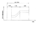
この差圧センサ36により検出されるフィルタ41の圧力損失ΔPは、温度センサ37からのフィルタ入口温度T1、温度センサ38からのフィルタ出口温度T2と共にエンジンコントローラ31に送られ、主にマイクロプロセッサで構成されるエンジンコントローラ31では、これらに基づいてフィルタ41の再生処理を行う。すなわち、フィルタ41の再生処理の期間を時系列的に図2に示したように前期(t1の時間)、中期(t2の時間)、後期(t3の時間)の3つの期間に分割し、分割した各期間毎に次のように排気の温度制御と排気中の酸素濃度制御とを行う。
【0034】
なお、制御波形がどうなるかは図22を参照しながら説明する。図22において第2段目に本実施形態によるフィルタ入口温度の目標値の特性を実線で、これに対して同じく第2段目に比較のため従来装置による目標温度をフィルタ入口温度の目標値であると解した場合のの特性を一点鎖線と破線で示している。また、第3段目に本実施形態による排気中の目標酸素濃度の特性を示す。
【0035】
〈1〉前期:フィルタ41のベッド温度を目標ベッド温度tTbedへと急速に上昇させるため、フィルタ入口温度の目標値tT1を目標ベッド温度tTbedより高く設定し、この目標値tT1が得られるように急速昇温制御を行う。
【0036】
ここで、目標ベッド温度tTbedは、フィルタ41に堆積したパティキュレートが自着火して速やかに燃焼する温度(例えば450℃〜650℃)である。
【0037】
ここでは目標値tT1として、図22第2段目の実線で示したように従来装置である一点鎖線や破線の場合よりずっと高い温度を設定するので、目標ベッド温度tTbedへの昇温の仕方が図22最下段の実線で示したように、一点鎖線や破線で示す従来装置の場合より急速に行われる。このため、本実施形態による昇温を「急速昇温」といっている。
【0038】
ただし、この前期の時間内では排気中の目標酸素濃度は定めず、従って酸素濃度制御は行わない(図22第3段目参照)。
【0039】
目標値tT1が得られるように急速昇温制御を行うと、フィルタ41のベッド温度が上昇して目標ベッド温度tTbedへと達するので、前期を終了して次の段階の中期に移行する。
【0040】
〈2〉中期:フィルタ41に堆積しているパティキュレートの燃焼速度を抑制するため、排気中の目標酸素濃度を図22第3段目に示したように低濃度に設定し、この低濃度の目標酸素濃度が得られるように酸素濃度制御(第1酸素濃度制御)を行う。
【0041】
また、中期になるとフィルタ入口温度の目標値tT1を目標ベッド温度tTbedへと切換えて維持する。これは、目標ベッド温度tTbedが得られているのに、さらに昇温制御を継続したのでは、ベッド温度を許容最高温度Tmaxを超えて上昇させてしまうので、これを避けるためである。
【0042】
低濃度に設定した目標酸素濃度が得られるように排気中の酸素濃度制御を行うと、フィルタ41に堆積したパティキュレートが急激に燃焼することなく燃焼が進行する。
【0043】
〈3〉後期:再生処理の終了間近にフィルタ41に残存するパティキュレートをもれなく燃やし切るため、排気中の目標酸素濃度を図22第3段目のように中期の場合より高濃度に設定し、この高濃度の目標酸素濃度が得られるように酸素濃度制御(第2酸素濃度制御)を行う。
【0044】
また、後期においても、フィルタ入口温度の目標値tT1は中期と変わらず目標ベッド温度tTbedに維持する。
【0045】
高濃度に設定した目標酸素濃度が得られるように排気中の酸素濃度制御を行うと、図22第1段目の実線のように再生効率が高まり、完全再生である100%へと近づいていく。
【0046】
次に、エンジンコントローラ31により行われるこれら制御の内容を詳述する。
【0047】
図3のフローチャートは再生処理を行うためのメインルーチンで、このフローは一定時間毎(例えば10ms毎)に実行する。
【0048】
ステップ1では再生処理フラグをみる。この再生処理フラグの設定については、図4のフローにより説明する。
【0049】
図4のフローは図3とは別に一定時間毎(例えば10ms毎)に実行する。図4においてステップ11ではフィルタ41の圧力損失ΔPを差圧センサ36の出力から読み込む。
【0050】
ステップ12では再生処理フラグをみる。再生処理フラグは後述する再生処理条件が成立したとき1となるフラグである。エンジン始動時にはゼロに初期設定されているので、再生処理条件の成立する前にはステップ13、14に進み、再生処理条件をみる。再生処理条件の成立は、フィルタ41の圧力損失ΔPが再生開始判定値ΔPHmaxを超えかつ再生実施条件にあることである。
【0051】
ここで、再生実施条件は例えばエンジンの回転速度と燃料噴射量(エンジン負荷相当)により定まる運転条件が図14に示した領域R1〜R4の領域にある場合に成立する。
【0052】
アイドル時やアイドルに近い低負荷域である領域R5にある場合に再生実施条件が非成立であるとするのは、アイドル時はもともと排気温度が低く、ポスト噴射及び吸気絞りを行ってもフィルタ41のベッド温度を目標ベッド温度tTbedへと上昇させることができないからである。
【0053】
このため圧力損失ΔPが再生開始判定値ΔPHmax以下のときやエンジンの運転条件が再生実施条件にないときにはそのまま今回の処理を終了する。
【0054】
フィルタ41の圧力損失ΔPが再生開始判定値ΔPHmaxを超えかつエンジンの回転速度と燃料噴射量により定まる運転条件が再生実施条件にあるときには再生処理を行うことができると判断しステップ15に進んで再生処理フラグ=1とする。
【0055】
この再生処理フラグ=1により次回からはステップ12よりステップ13へと進むことができないため、そのまま処理を終了する。すなわち、再生処理フラグは、ステップ15で1になった後は後述する再生処理の中断時にも1のままであり(図11参照)、後述する再生処理の終了のタイミングで0にリセットされるようになっている(図5ステップ31参照)。
【0056】
図3に戻り、ステップ1で再生処理フラグ=1であるときには再生処理を行うためステップ2以降に進む。ステップ2では再生フェーズを設定する。この再生フェーズの設定については図5のフローにより説明する。
【0057】
図5のフローは再生処理の開始からの経過時間Tと設定時間t1、t2、t3とを比較して、再生フェーズの前期、中期、後期を設定するためのもので、一定時間毎(例えば10ms毎)に実行する。
【0058】
ステップ21では再生終了フラグをみる。再生終了フラグはゼロに初期設定されているので、ステップ22に進み、再生中断フラグをみる。再生中断フラグもゼロに初期設定されており、図11で後述するように再生処理の終了前に再生処理を継続できなくなったとき1となるフラグである。
【0059】
いまは再生処理の開始直後にあるとして説明すると、再生中断フラグ=0であるのでステップ23に進み再生処理フラグをみる。再生処理フラグ=0のときはそのまま今回の処理を終了する。
【0060】
再生処理フラグ=1であるときにはステップ24に進み、タイマ値T(ゼロに初期設定)を、
T=Tz+ΔT…(1)
ただし、ΔT:演算周期(=10ms)、
Tz:タイマ値の前回値、
の式によりインクリメントする。このタイマは再生処理開始からの経過時間(つまり再生処理時間)計測するためのものである。
【0061】
ステップ25、26ではこのタイマ値Tと設定時間t1、t2、t3(図2参照)とに基づいて、次のように再生フェーズの各期間を設定する。
【0062】
(1)T<t1であるとき:
ステップ25よりステップ27進み再生フェーズを前期に設定する。
【0063】
(2)t1≦T<t1+t2であるとき:
ステップ25よりステップ28に進み再生フェーズを中期に設定する。
【0064】
(3)t1+t2≦T<t1+t2+t3であるとき:
ステップ25、26よりステップ29に進み再生フェーズを後期に設定する。
【0065】
(4)t1+t2+t3≦Tであるとき:
このときには再生処理の終了であると判断し、ステップ25、26よりステップ30に進み再生終了フラグ=1とする。また、次回の再生処理に備えるためステップ31、32で再生処理フラグ=0かつタイマ値T=0とする。
【0066】
ステップ25で用いる上記の設定時間t1、t2、t3は一定値でもかまわないが、ここでは、t1とt2については次のように可変値で設定している。
【0067】
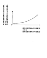
図6は再生処理開始時の実際のベッド温度に対するt1の設定例である。フィルタ41を再生するにはフィルタ41に堆積しているパティキュレートが自着火して燃焼し得る温度である目標ベッド温度tTbedにまで上昇させなければならないが、t1は再生処理の開始より目標ベッド温度tTbedに上昇させるまでの時間である。この時間t1は図6のように再生処理開始時のベッド温度が高くなるほど小さくなる。これは再生処理開始時のベッド温度が高ければフィルタのベッド温度を目標ベッド温度まで上昇させるに要する時間も短くて済むからである。
【0068】
また、tTbed以上の温度域ではt1=0である。これはtTbed以上の温度域では昇温制御を行わなくともフィルタ41に堆積しているパティキュレートが自着火して燃焼するので、このときにはt1をゼロとして次の段階の中期へと即座に移行させるためである。
【0069】
また、再生処理開始時のベッド温度が所定値Taより低い温度域では一定値としている。これは、Taより低い温度域ではフィルタ41を昇温させようとしても目標ベッド温度tTbedにまで昇温できないので、一定値としたものである。
【0070】
なお、図6において横軸の再生処理開始時の実際のベッド温度は、再生処理開始時にフィルタ41の前後に設けた温度センサ37、38により検出される2つの温度T1、T2から、
Tbed=b1・T1+b2・T2…(2)
ただし、Tbed:再生処理開始時のベッド温度、
b1、b2:定数、
の式により推定(算出)すればよい。(2)式のb1、b2は実験により決まる値である。
【0071】
図7は再生処理開始時のパティキュレート堆積量(図ではPM堆積量で略記)に対するt2の設定例である。フィルタ41のベッド温度を目標ベッド温度tTbedにまで上昇させた後は、フィルタ41に堆積しているパティキュレートが自着火して燃焼する。この場合に、排気中の酸素濃度が十分に大きい状態(空燃比でいうと理論空燃比よりリーン側の所定値A)ではフィルタ41に堆積している大量のパティキュレートが急激に燃焼し、これによってフィルタ41のベッド温度が許容最高温度Tmaxを超えて上昇し、フィルタ41に熱劣化が生じて耐久性が低下しかねない。このため、フィルタ41に堆積している大量のパティキュレートが急激には燃えない程度の低い酸素濃度(空燃比でいうと理論空燃比よりはリーン側で上記のAよりはリッチ側の所定値B)に維持する時間(期間)がt2である。この時間t2は再生開始時のパティキュレート堆積量が大きくなるほど長くなる。
【0072】
また、再生開始時のパティキュレート堆積量が最大パティキュレート堆積量pmax以上ではt2を一定としている。
【0073】
また、再生開始時のパティキュレート堆積量が所定値p以下の堆積量のときt2=0としている。これは、p以下のパティキュレート堆積量の場合には、中期を省略して後期に移行し、その総てを一気に燃焼させてもフィルタ41のベッド温度の上昇が少なく、フィルタ41のベッド温度が許容最高温度Tmaxに達することはないので、中期の段階を省略して即座に後期へと移行させるためである。すなわち、所定値pは、中期を介さずとも後期においてフィルタ41のベッド温度が許容最高温度を超えないパティキュレート堆積量の最大量付近に設定している。
【0074】
ただし、所定量のパテキュレートが堆積している場合に限って再生処理を開始するものとすれば、再生処理開始時のパテキュレート堆積量がp以下である事態はあり得ない。従って、これはむしろ後述する再生処理再開時に意味があると考えられる。すなわち、中期の期間中に再生処理が中断されれば、フィルタのパティキュレート堆積量がp以下の状態にとどまる事態が考えられ、このときには再生処理の再開時のパティキュレート堆積量がp以下の状態になる。従って、中期の期間中の再生処理の中断により再生処理再開時のパティキュレート堆積量がp以下のときには、即座に後期に移行して高濃度の目標酸素濃度への酸素濃度制御を行わせることで、再生処理期間を短縮することができる。
【0075】
なお、図7において、横軸の再生処理開始時のパティキュレート堆積量は、再生処理開始時のフィルタの圧力損失から図8を内容とするテーブルを検索することにより演算すればよい。
【0076】
図5に戻り、ステップ22で再生中断フラグ=1であるとき(再生処理の中断中)にはステップ36に進んで、
T=Tz−a×ΔT…(3)
ただし、a:所定値、
の式により再生処理開始からの経過時間を表すタイマ値Tを更新する。
【0077】
これは、一般的には再生処理中の中断時間は再生処理時間にカウントしていないのであるが、本実施形態では、再生処理中の中断に伴うフィルタのベッド温度の挙動に着目して次のようにタイマ値Tを補正するようにしている。
【0078】
(1)前期:
図9において再生処理開始後に再生処理の中断の機会が一度もなければ、本実施形態の急速昇温制御により、再生処理開始よりt1が経過したタイミングで実際のベッド温度が目標ベッド温度tTbedに達する。
【0079】
これに対して再生処理開始後に再生実施条件が不成立となり、再生処理(急速昇温制御)が中止され、その後に再生処理の再開で急速昇温制御が実行されたとすると、ベッド温度は再生処理中断時の温度Tcより低下し、再生処理再開時の温度Tdより再び上昇して目標ベッド温度tTbedへと達する(一点鎖線参照)。すなわち、再生処理の中断に伴うベッド温度の低下により、目標ベッド温度tTbedに達するまでの時間がt1よりt1´へと長引く。このため、再生処理の中断があるときにはt1´まで待って次の段階である中期へと移行させなければならないところ、再生処理の中断があるときにもt1が経過したタイミングで中期へと移行させたのでは、中期へと移行させるのが早すぎ、中期においてフィルタに堆積しているパティキュレートを十分に燃焼させることができなくなる。
【0080】
そこで、前期の時間内に再生処理の中断があるときには中期に移行させるのを遅らせるため、上記(3)式の所定値aに正の値を与えてタイマ値Tを小さくなる側に補正する。
【0081】
(2)中期:
中期の期間中での再生処理の中断は、前期の期間中での再生処理の中断と少し異なる。すなわち、中期の期間中での中断初期においてはフィルタ41の有する熱容量分でフィルタ41に堆積しているパティキュレートの燃焼がしばらく持続し、燃焼がやんだ後にベッド温度が低下していく。
【0082】
従って、このときにはパティキュレートの燃焼が持続する中断初期の期間とベッド温度が低下してゆく中断初期以降の期間との2つに分けて考える必要があり、この場合、中断初期の期間においては、再生処理の中断中といえどもパティキュレートの燃焼が継続しているのであるから、再生処理の中断のない場合の中期での再生処理中と同じである。このため、この中断初期の期間もタイマ値Tに加えるべきであり、加えないとしたら後期へと移行させるのが遅れてしまう。
【0083】
そこで、中期の期間中での中断時間が中断初期の期間内にある場合には後期へと移行させるのを早めるため、上記(3)式の所定値aに負の値を与えてタイマ値Tを大きくなる側に補正する。
【0084】
一方、中断初期移行の期間ではベッド温度が低下するのであるから、これは前述した前期の期間中の再生処理の中断と同じ扱いとすればよい。
【0085】
そこで、中期の期間中での中断時間が中断初期以降の期間にまで長くなったときには後期に移行させるのを遅らせるため、上記(3)式の所定値aに正の値を与えてタイマ値Tを小さくなる側に補正する。
【0086】
(3)後期:
後期の期間中での再生処理の中断は前述した中期の期間中での再生処理の中断と同様に扱えばよい。
【0087】
こうした考えにより、図5において上記(3)式の所定値aに次のようにして再生フェーズの各段階毎に異なる値を設定しておき、中断中にはその設定された所定値a1、a2、a3により上記(3)式によりタイマ値Tを補正する。
【0088】
(1)前期(T<t1であるとき):
ステップ25よりステップ33進み前期の期間中の中断に備えて所定値aに所定値aにa1を入れる。
【0089】
(2)中期(t1≦T<t1+t2であるとき):
ステップ25よりステップ34に進み中期の期間中の中断に備えて所定値aにa2を入れる。
【0090】
(3)後期(t1+t2≦T<t1+t2+t3であるとき):
ステップ25、26よりステップ35に進み後期の期間中の中断に備えて所定値aにa3を入れる。
【0091】
上記の所定値a1は図10左上に示したように前期での中断時間に関係なく正の一定値である。この結果、図10左下に示したように前期においては中断がないとき(中断時間=0)のタイマ値Tに対して中断時間が長くなるほど小さくなる側にタイマ値Tが補正される。
【0092】
これに対して所定値a2(またはa3)は図10右上に示したように中期での中断時間に応じ、その中断時間が所定値tb以下の期間(中断初期の期間)では負の一定値で、その中断期間がtbを超える期間(中断初期以降の期間)になると正の一定値である。この場合、中期(または後期)におけるtbを超える期間での温度低下のほうが、前期における温度低下より激しいので、これに合わせて正の値の区間のa2(またはa3)のほうをa1より大きくしている。
【0093】
この結果、図10右下に示したように中期(または後期)での中断がないときのタイマ値Tに対して中断時間が所定値tb以下のときにはタイマ値Tが大きくなる側に補正され、これに対して中期(または後期)での中断時間が所定値tbを超えると、前期における中断と同じに中断時間が長くなるほど小さくなる側にタイマ値Tが補正される。
【0094】
なお、上記の所定値a1、a2、a3、tb並びに図10左下の所定値tc、図10右下の所定値tdの実際の値は、フィルタ41の熱容量や放熱特性、エンジン1の排気温度の特性を考慮して実験的に求める必要がある。また、a2(またはa3)の値は中断時間がtb未満のときとtb以上のときとで切り換える必要があり、そのためには中断のタイミングよりタイマを起動して中断時間を計測すればよい。
【0095】
図11のフローは図5のステップ22において用いる再生中断フラグを設定するためのもので、一定時間毎(例えば10ms毎)に実行する。
【0096】
ステップ41では再生中断フラグをみる。再生中断フラグはエンジン始動時にゼロに初期設定されているので、ステップ42に進み、再生処理フラグをみる。再生処理フラグ=1のときにはステップ43に進み、再生実施条件が成立しているかどうかみる。再生実施条件が成立しているときにはそのまま今回の処理を終了するが、再生実施条件が成立していないときには再生処理を中断するためステップ44に進み、再生中断フラグ=1とする。
【0097】
再生中断フラグ=1より次回にはステップ41よりステップ45に進み、再生実施条件をみる。再生処理の中断中でも再生実施条件が成立しない間は中断を継続するためステップ44の操作を実行し、これに対して中断中に再生実施条件が成立したときには再び再生処理を再開させるためステップ46に進み再生中断フラグ=0とする。
【0098】
このようにして設定される再生中断フラグを図5のステップ22で用いる。
【0099】
なお、図示しないが、再生中断フラグ=1により再生処理が中断される。すなわち、前期の期間中に再生処理が中断されると、上記〈1〉の急速昇温制御が中断され、また中期や後期の期間中に再生処理が中断されると、上記〈2〉や〈3〉の酸素濃度制御が中断される。
【0100】
これに対して再生中断フラグが再びゼロになったときには再生処理が再開される。すなわち、急速昇温制御が中断されていればその中断されていた急速昇温制御が再開され、また酸素濃度制御が中断されていればその中断されていた酸素濃度制御が再開される。
【0101】
このため、中断後の再生処理再開時には次のようにしてt1、t2を設定し直すようにしている。
【0102】
(ア)前期の期間中に中断がありその後に再生処理が再開されたとき:
再生処理再開時のベッド温度から図6を内容とするテーブルを検索することによりt1を、また再生処理再開時のパティキュレート堆積量から図7を内容とするテーブルを検索することによりt2を演算し、このt1、t2を再生処理開始時に既に演算しているt1、t2に置き代えて用いて図5のステップ25での判定を行う。
【0103】
(イ)中期や後期の期間中に中断がありその後に再生処理が再開されたとき:再生処理再開時のパティキュレート堆積量から図7を内容とするテーブルを検索することによりt2を演算し、このt2を再生処理開始時に既に演算しているt2に置き代えて用いて図5のステップ25での判定を行う。
【0104】
なお、上記(ア)、(イ)において図7の横軸の再生処理再開時のパテキュレート堆積量は、再生処理再開時のフィルタ圧力損失から図8を内容とするテーブルを検索することにより演算する。
【0105】
このようにして図5の再生フェーズの各段階の設定を総て終了したら図3に戻り、ステップ3では現在の処理タイミングが再生フェーズのいずれの段階にあるのかをみて、次のように各制御を行う。すなわち、前期であればステップ4に進みフィルタ入口温度の目標値tT1を目標ベッド温度tTbedより高く設定し、この目標値tT1が得られるように排気温度制御(急速昇温制御)を行う。
【0106】
中期であるときにはステップ5、7に進みフィルタ入口温度の目標値tT1を目標ベッド温度tTbedに切換えて維持する共に、排気中の目標酸素濃度を低濃度に設定した酸素濃度制御(第1酸素濃度制御)を行う。後期になるとステップ6、7に進みフィルタ入口温度の目標値tT1は中期と同じく目標ベッド温度tTbedに維持すると共に、排気中の目標酸素濃度を中期の場合より高濃度に設定した酸素濃度制御(第2酸素濃度制御)を行う。
【0107】
ここで、図3のステップ4〜7での制御を急速昇温制御と酸素濃度制御に分けてさらに説明する。
【0108】
〔1〕急速昇温制御:
〔1〕−1.急速昇温制御方法その1:
図12は本実施形態によるフィルタ入口温度の制御結果とこれによってフィルタのベッド温度がどのように変化するのかを表している。すなわち、再生処理の開始時にはフィルタ入口温度の目標値tT1として目標ベッド温度tTbedよりも高い温度を設定し、前期の総ての期間に亘って、この目標値tT1が得られるように排気昇温手段を働かせる。
【0109】
前期の期間(t1)が終了したら、フィルタ入口温度の目標値tT1を目標ベッド温度tTbedへと切換えて維持する。
【0110】
〔1〕−2.急速昇温制御方法その2:
図13は前期の期間を前半と後半のほぼ2つに分け、前半部分で図12の場合よりもさらに高い温度をフィルタ入口温度の目標値tT1に設定し、後半部分で徐々に目標ベッド温度tTbedへと近づくよう目標値tT1を調整する(下段の実線参照)。そして、この目標値tT1が得られるように排気昇温手段を働かせる。
【0111】
これによって目標ベッド温度tTbedへと上昇させるに要する時間を図12の場合のt1よりt1´へと短縮することができ、さらに図12の場合に生じていたベッド温度のオーバーシュートをも防止できる。比較のため図13には図12の場合を破線で示している。
【0112】
〔1〕−3.排気昇温手段:
排気温度は燃料噴射量(エンジン負荷相当)と回転速度により異なるので、図14に示したように全運転領域を大きく5つに区分けし、区分けした各運転領域での排気温度に応じて、次のように排気昇温手段を働かせることにより、図12に示したフィルタ入口温度の目標値tT1を実現する。
【0113】
領域R1:全負荷付近の領域であり、この領域では排気温度が目標ベッド温度tTbedとなり、排気昇温手段を働かせなくても自然にパティキュレートが燃焼して再生が行われるため、排気昇温手段は働かせない。
【0114】
領域R2:領域R1より低負荷側である領域R2〜R5ではフィルタ入口温度T1がその目標値tT1とならないため排気昇温手段を働かせる必要がある。このため領域R2ではまず排気昇温手段である燃料噴射装置10から噴射される燃料の噴射時期(メイン噴射時期)を通常(再生処理前)よりも遅らせることによって排気温度を上昇させる。メイン噴射時期の遅角によってフィルタ入口温度T1はその目標値tT1へと上昇する。
【0115】
領域R3:メイン噴射時期の遅角だけではフィルタ入口温度T1をその目標値tT1にできない領域であり、メイン噴射時期の遅角に代わってポスト噴射(メイン噴射後にさらに膨張行程で噴射すること)を行うことによって排気を昇温させる。この膨張行程でのポスト噴射によりフィルタ入口温度T1はその目標値tT1へと上昇する。
【0116】
領域R4:ポスト噴射のみによってはフィルタ入口温度T1をその目標値tT1にできない領域であり、ポスト噴射に加えて、別の排気昇温手段である吸気絞り装置を用いて排気を昇温させる。この制御によりフィルタ入口温度T1はその目標値tT1へと上昇する。
【0117】
このため、図1においてコレクタ3a入口に、アクチュエータ43により駆動される吸気絞り弁42(吸気絞り装置)が設けられている。上記のアクチュエータ43は、制御圧力に応動して吸気絞り弁42を駆動するダイヤフラムアクチュエータ44と、このダイヤフラムアクチュエータ44への制御圧力を調整する圧力制御弁45とからなり、吸気絞り弁42が目標開度まで閉じられるように、デューティ制御信号が作られ、このデューティ制御信号が圧力制御弁45に出力される。
【0118】
なお、本実施形態のように可変容量ターボ過給機21やコモンレール式燃料噴射装置10を備える場合には、R2、R3、R4の領域でこれらも排気昇温手段として働かせ、目標値tT1へと昇温させることが可能である。例えば可変ノズル24を開くとタービン22の仕事が減るため吸入空気量が減って空気過剰率が小さくなり、これによってフィルタ入口温度T1が上昇する。また、コモンレール圧を低くすると噴射期間が長引いて燃焼期間が長くなる。すると、燃焼が悪化してエンジントルクが低下する。このエンジントルクの低下を補おうと燃料噴射量が増え、これによってフィルタ入口温度T1が上昇する。
【0119】
領域R5:アイドル時のように排気温度がもともと低い低負荷域であり、この領域では上記いずれの方法によってもフィルタ入口温度をその目標値tT1へと上昇させることができないので、再生処理は行わない(排気昇温手段は働かせない)。
【0120】
一方、図13に示した目標値tT1は、図14に示した昇温制御をベースとして、図14に示した領域R3、R4において感度の高いポスト噴射量を時間とともに変化させることで達成することができる。例えば、エンジンの回転速度と負荷から所定のマップ(図示しない)を検索することによりベース排気温度(排気昇温手段を働かせない状態での排気温度のこと)Tbaseを、またエンジンの回転速度とエンジントルクとから図15を内容とするマップを検索することにより排気温度を1℃上げるのに必要なポスト噴射増加量ΔPostを演算し、これらを用いて
ΔQp=ΔPost×(tT1−Tbase)…(4)
ただし、tT1:フィルタ入口温度の目標値、
の式によりポスト噴射量の上乗せ量ΔQpを演算し、この上乗せ量ΔQpを図14に示した領域R3、R4でのポスト噴射量に加えればよい。
【0121】
〔2〕酸素濃度制御:
〔2〕−1.中期の酸素濃度制御(第1酸素濃度制御):
図16にパティキュレート堆積量(PM堆積量)が多い状態(つまり中期)で再生処理を行ったときのフィルタ入口温度、排気中酸素濃度とフィルタ41のベッド温度の最高温度との関係を示すと、パテキュレート堆積量が多いため曲線と曲線の間の間隔が短く、これは温度勾配が急であることを表している。
【0122】
このようにパティキュレート堆積量が多い状態では、低酸素濃度側に目標酸素濃度の制御範囲を設けることで、フィルタ41のベッド温度の許容最高温度内でフィルタ41の再生処理を行うことができる。
【0123】
ここで、排気中の目標酸素濃度は空燃比に換算すると理論空燃比よりリーン側(例えば空気過剰率で1.5程度)である。パティキュレート堆積量が多い状態で高濃度の酸素があると、パティキュレートの燃焼速度が大きいためにフィルタ41に堆積しているパティキュレートが急激に燃えるので、これを抑えるため排気中の目標酸素濃度を低酸素濃度に設定している。
【0124】
また、目標酸素濃度の制御範囲に幅を設けているのは、バラツキと過渡時の制御遅れとを考慮したものである。
【0125】
〔2〕−2.後期の酸素濃度制御(第2酸素濃度制御):
図17には今度は、パティキュレート堆積量が少ない状態(つまり後期)で再生処理を行ったときのフィルタ入口温度、排気中酸素濃度とフィルタ41のベッド温度の最高温度との関係を示し、パティキュレート堆積量が少ない状態では曲線と曲線の間隔が広がり(温度勾配が緩やかとなり)、かつベッド温度の許容最高温度の位置も図16の場合より右方向に移動している。
【0126】
このため、パティキュレート堆積量が少ない状態では、排気中の酸素濃度を中期に比べ大きくしても、フィルタ41の再生処理中のベッド温度の最高温度を許容最高温度以下に保つことができるので、後期には図中1)のように中期よりも目標酸素濃度を大きくする。これによって十分な酸素を供給してパティキュレートの燃焼速度を大きくし、フィルタ41に燃え残っているパティキュレートの総てを短期間で完全に燃え切らせることが可能となる。さらに、図中2)のようにフィルタ入口温度の目標値tT1をも上昇させることで、さらに再生処理時間の短縮とパティキュレートの再生効率の向上を図ることができる。
【0127】
〔2〕−3.酸素濃度制御の制御結果:
図18に本実施形態による排気中酸素濃度の制御目標(目標酸素濃度)とその制御結果としての実際の排気中酸素濃度の変化を示す。図示のように中期に低酸素濃度に制御されていたものが、後期になると、それより高い酸素濃度へと切換えられている。なお、中期、後期を除く他の期間(前期を含む)では排気中酸素濃度が激しく変化している。これは、他の期間ではもともと排気中の酸素濃度制御を行っていないこと、また加速や減速が繰り返される過渡時のものであるからである。
【0128】
図18は排気中の目標酸素濃度を低濃度から高濃度へと単純に2段階に切換えるものであるが、図19のように、中期の後半部分で徐々に目標酸素濃度を大きくして後期の目標酸素濃度に滑らかにつなぐことにより、図18の場合より再生処理期間の短縮を図ることも可能である。
【0129】
〔2〕−4.酸素濃度制御手段:
排気中の目標酸素濃度をtRO2[%]、この目標酸素濃度tRO2が得られるときの空気過剰率を目標空気過剰率tλとすると、次式が成立する。
【0130】
tλ=21/(21−tRO2)…(5)
ただし、21:新気中の酸素濃度[%]、
なお、(5)式は燃焼による作動ガスのモル増加を考慮していないが、制御精度をさらに向上させるためにこの効果を(5)式に入れることもできる。
【0131】
(5)式の目標空気過剰率tλを得るための制御には吸入新気量の制御と、燃料噴射の制御とがある。
【0132】
〔2〕−4−1.吸入新気量の制御:
(5)式の目標空気過剰率tλを得るための吸入新気量をtQaとすれば、燃料噴射量Qfとの間に次式が成立する。
【0133】
tQa=Qf×理論空燃比×tλ…(6)
(5)式を(6)式に代入すると次式が得られる。
【0134】
tQa=Qa×理論空燃比×21/(21−tRO2)…(7)
従って、(7)式の目標吸入新気量tQaが得られるように吸入新気量を制御する。
【0135】
この場合、吸入新気量制御手段により、カバーできる運転領域が図20に示したように異なるので、吸入新気量制御手段に応じて次のように酸素濃度制御を行う。
【0136】
▲1▼吸入新気量制御手段が可変容量ターボ過給機21のとき:
R6、R7、R8の領域では可変容量ターボ過給機21により吸入新気量を制御する。例えば、可変ノズル24の開度を小さくするとタービン22の回転速度が高くなり、吸入新気量を増やす(酸素濃度を大きくする)ことができる。この逆に可変ノズル24の開度を大きくするとタービン22の回転速度が低くなり、吸入新気量を減らすことができる。
【0137】
▲2▼吸入新気量制御手段がEGR装置のとき:
R7、R8の領域ではEGR弁6(EGR装置)により吸入新気量を制御する。例えば、EGR率やEGR量を増加すれば吸入新気量を減らすことが、この逆にEGR率やEGR量を小さくすれば吸入新気量を増やすことができる。
【0138】
▲3▼吸入新気量制御手段が吸気絞り弁42(吸気絞り装置)のとき:
R8の領域では吸気絞り弁42により吸入新気量を制御する。例えば、吸気絞り弁42を閉じれば吸入新気量を減らすことが、この逆に吸気絞り弁42を戻せば吸入新気量を増やすことができる。
【0139】
〔2〕−4−2.燃料噴射の制御:
上記(5)式の目標空気過剰率tλを得るための目標燃料噴射量をtQfとすれば、吸入新気量Qaとの間に次式が成立する。
【0140】
Qa=tQf×理論空燃比×tλ…(8)
(5)式、(8)式を目標燃料噴射量tQfについて解くと次式が得られる。
【0141】
tQf=Qa×(1/理論空燃比)×(21−tRO2)/21…(9)
従って、(9)式の目標燃料噴射量tQfが得られるように燃料噴射を制御する。
【0142】
この場合、燃料噴射制御手段によりカバーできる運転領域が図21に示したように異なるので、燃料噴射制御手段に応じて次のように酸素濃度制御を行う。
【0143】
領域R9:メイン噴射時期を遅角しつつ(9)式の目標燃料噴射量tQfが得られるように燃料噴射を制御する。
【0144】
領域R10:メイン噴射時期の遅角とポスト噴射を行いつつ(9)式の目標燃料噴射量tQfが得られるように燃料噴射を制御する。ポスト噴射量を増加すれば燃料噴射量を増加する(酸素濃度を小さくする)ことができる。ポスト噴射はエンジンの膨張行程で行うため、トルク増加をあまり伴わずに噴射量の増加を行うことができる。そしてトルク増加分はメイン噴射量を減少してコントロールする。
【0145】
領域R11:ポスト噴射と吸気絞りとメイン噴射時期とにより燃料噴射量を制御する。例えば吸気絞りを行うとポンピングロスが増加するため、これを補う分だけポスト噴射量を増加できる。また、このときのメイン噴射時期は噴射量を制御しない場合よりも進角側に制御する。
【0146】
〔2〕−4−3.排気中酸素濃度のフィードバック制御:
上記の〔2〕−4−1、〔2〕−4−2での制御はオープンループ制御であるが、フィードバック制御を行わせることもできる。例えばエアフローメータ35出力より検出される実際の吸入新気量が上記(7)式の目標吸入新気量tQaと一致するように、あるいは実際の燃料噴射量が上記(9)式の目標燃料噴射量tQfと一致するようにフィードバック制御する。
【0147】
また、排気通路2に排気中の実際の酸素濃度を検出するセンサ(例えば広域空燃比センサ)を設けておき、このセンサにより検出される排気中の実際の酸素濃度が目標酸素濃度と一致するようにフィードバック制御を行わせることもできる。
【0148】
ここで、本実施形態の作用を図22を参照しながら説明すると、同図は上から再生効率、フィルタ入口温度の目標値、排気中の目標酸素濃度、フィルタのベッド温度の最高温度の動きをモデル的に示している。なお、第1段目、第2段目、第4段目においては本実施形態の場合を実線で、これに対して従来装置の場合を一点鎖線と破線で示している。
【0149】
(1)再生処理の前期:
前期には第2段目のようにフィルタ入口温度の目標値tT1(実線参照)が従来装置(一点鎖線と破線参照)より高く設定されるので、従来装置の場合よりフィルタ41のベッド温度の最高温度が最下段のように目標ベッド温度tTbedまでに急速に上昇している。
【0150】
(2)再生処理の中期:
▲1▼第3段目のように排気中の目標酸素濃度を低濃度側に設定して、フィルタ41に堆積しているパティキュレートの燃焼速度を抑制するので、フィルタのベッド温度の最高温度が許容最高温度を上回ることがなく(最下段の実線参照)、これによりフィルタ41の耐久性が損なわれることがない。
【0151】
▲2▼排気温度を低下させることによりパティキュレートの燃焼速度を抑制する方法もあるが、この排気温度によるパティキュレート燃焼速度制御方法だと、排気やフィルタ41の熱慣性の影響を受けて制御の応答性が悪くなる。これに対して本実施形態では、こうした排気温度によるパティキュレート燃焼速度制御方法でないため排気やフィルタ41の熱慣性の影響を排除でき、制御応答性がよく制御の信頼性が高い。
【0152】
▲3▼排気温度によるパティキュレート燃焼速度制御方法だと、パティキュレートの燃焼速度を抑えようと排気温度を低下させたとき、これに伴ってフィルタ41のベッド温度が目標ベッド温度以下に低下するようだと再生不良が生じ得る。これに対して本実施形態では、目標ベッド温度を保ちつつ、パテキュレートの燃焼速度の抑制は酸素濃度制御で行うので、パテキュレートの燃焼中においても、フィルタ41のベッド温度の最高温度が目標ベッド温度を下回ることがない。すなわち、本実施形態は、排気温度によるパティキュレート燃焼速度制御方法でないため、フィルタ41のベッド温度を目標ベッド温度より低下させる必要がなく、これによってフィルタ周辺の温度低下による再生不良を防止できる。
【0153】
(3)再生処理の後期:
第3段目のように排気中の目標酸素濃度を中期の段階より大きくすることで、再生処理の終了間近にフィルタ41に残存するパティキュレートの総てを迅速にかつ確実に燃え切らせることができ、これにより再生処理時間の短縮、ならびにほぼ完全なフィルタ再生を図ることができる。
【0154】
その結果、本実施形態では次の効果が得られる。
【0155】
(1)再生処理時間の短縮:
再生処理に要する燃料消費の増加を最小限とし、燃費悪化を抑制できる。再生処理中の高温維持時間が減少し、フィルタの熱劣化を抑制でき、排気性能の向上、寿命の延長が図れる。
【0156】
(2)完全再生の実現:
燃え残りのパティキュレートによる圧損上昇がなくなるので燃費悪化を防止できる。また、燃え残りパティキュレートの上に新たなパティキュレートが堆積して生じる不均一パティキュレート堆積は、局所的な急激なパティキュレート燃焼を引き起こし、その部分で耐久性が低下する可能性があるが、これを防止できる。
【0157】
また、本実施形態(請求項2に記載の発明)によれば、t1(急速昇温制御期間)を再生処理開始時のフィルタのベッド温度に基づいて設定するので、t1を、再生処理開始時のフィルタのベッド温度が相違しても精度良く与えることができる。
【0158】
また、本実施形態(請求項9に記載の発明)によれば、前期の期間(急速昇温制御期間)のフィルタ入口温度の目標値を、当初は中期、後期(酸素濃度制御期間)のフィルタ入口温度の目標値よりも高く設定し、その後に中期、後期のフィルタ入口温度の目標値まで徐々に低下するように設定するので(図13参照)、パティキュレートが自着火する温度へと上昇させるに要する時間を短縮することができると共に、ベッド温度のオーバーシュートをも防止できる。
【0159】
また、本実施形態(請求項15に記載の発明)によれば、中期の期間(第1酸素濃度制御期間)において排気中の目標酸素濃度を後期の期間(第2酸素濃度制御期間)の排気中の目標酸素濃度に向けて徐々に大きくするので(図19参照)、排気中の目標酸素濃度をステップ的に切換える場合より再生処理期間を短縮できる。
【0160】
また、再生処理再開時のパティキュレート堆積量が所定値p以下の場合には、低酸素濃度を目標とする酸素濃度制御(第1酸素濃度制御)を省略して高酸素濃度を目標とする酸素濃度制御(第2酸素濃度制御)に移行し、フィルタに残存するパティキュレートの総てを一気に燃焼させてもフィルタのベッド温度の上昇が少なく、フィルタのベッド温度が許容最高温度に達することはない。すなわち、本実施形態(請求項34に記載の発明)によれば、低酸素濃度を目標とする酸素濃度制御の中断により再生処理再開時のパティキュレート堆積量が所定値p以下のときには、即座に高酸素濃度を目標とする酸素濃度制御に移行させることで、再生処理期間を短縮することができる。
【0161】
急速昇温制御が中断されると、ベッド温度はその中断時の温度より低下し、再生処理再開時の温度より再び上昇してパティキュレートが自着火する温度へと上昇する。すなわち、急速昇温制御の中断に伴うベッド温度の低下により、パティキュレートが自着火する温度に達するまでの時間が中断がない場合より長引く。このため、急速昇温制御の中断があるときには中断がない場合より遅らせて次の段階である酸素濃度制御へと移行させなければならないところ、急速昇温制御の中断があるときにも中断がないときと同じタイミングで酸素濃度制御へと移行させたのでは、酸素濃度制御へと移行させるのが早すぎ、酸素濃度制御期間においてフィルタに堆積しているパティキュレートを十分に燃焼させることができなくなる。これに対して、本実施形態(請求項36に記載の発明)によれば、急速昇温制御に中断があるとき、タイマ値T(再生処理開始からの経過時間)を、急速昇温制御が中断された時間に基づいて短くなる側に補正するので(図10左下参照)、急速昇温制御が中断されることがあっても、適切なタイミングで酸素濃度制御へと移行させることができる。
【0162】
酸素濃度制御中の中断は、急速昇温制御中の中断と少し異なる。すなわち、酸素濃度制御中の中断初期においてはフィルタ41の有する熱容量分でフィルタ41に堆積しているパティキュレートの燃焼がしばらく持続し、燃焼がやんだ後にベッド温度が低下していく。従って、このときにはパティキュレートの燃焼が持続する中断初期の期間とベッド温度が低下してゆく中断初期以降の期間との2つに分けて考える必要があり、この場合、中断初期の期間においては、酸素濃度制御の中断中といえどもパティキュレートの燃焼が継続しているのであるから、酸素濃度制御の中断のない場合の酸素濃度制御中と同じである。このため、この中断初期の期間も急速昇温制御の終了からの経過時間や低酸素濃度を目標とする酸素濃度制御(第1酸素濃度制御)の終了からの経過時間に加えるべきであり、加えないとしたら高酸素濃度を目標とする酸素濃度制御(第2酸素濃度制御)へと移行させるのが遅れたり、再生処理の終了が遅れてしまう。
【0163】
これに対して、本実施形態(請求項37に記載の発明)によれば、低酸素濃度を目標とする酸素濃度制御が中断された時間に基づいて、その中断時間が所定時間tbまではタイマ値T(急速昇温制御の終了からの経過時間)を長くなる側に、またその中断時間が所定時間tbを超えるとタイマ値Tを短くなる側に補正するので(図10右下参照)、低酸素濃度を目標とする酸素濃度制御が中断されることがあっても、適切なタイミングで高酸素濃度を目標とする酸素濃度制御へと移行させることができる。
【0164】
また、本実施形態(請求項38に記載の発明)によれば、高酸素濃度を目標とする酸素濃度制御が中断された時間に基づいて、その中断時間が所定時間tbまではタイマ値T(第1酸素濃度制御の終了からの経過時間)を長くなる側に、またその中断時間が所定時間tbを超えるとタイマ値Tを短くなる側に補正するので(図10右下参照)、高酸素濃度を目標とする酸素濃度制御が中断されることがあっても適切なタイミングで再生処理を終了させることができる。
【図面の簡単な説明】
【図1】本発明の一実施形態を示す概略構成図。
【図2】再生処理期間の3つの段階を示す特性図。
【図3】再生処理の全体を説明するためのフローチャート。
【図4】再生処理フラグの設定を説明するためのフローチャート。
【図5】再生フェーズの設定を説明するためのフローチャート。
【図6】設定時間t1の特性図。
【図7】設定時間t2の特性図。
【図8】パティキュレート堆積量に対するフィルタ圧力損失の特性図。
【図9】急速昇温制御の途中で中断があった場合のフィルタのベッド温度の挙動を示す波形図。
【図10】所定値a1、a2、a3の特性図。
【図11】再生中断フラグの設定を説明するためのフローチャート。
【図12】前期におけるフィルタ入口温度の目標値の設定方法を説明するための波形図。
【図13】他の実施形態の前期におけるフィルタ入口温度の目標値の設定方法を説明するための波形図。
【図14】排気昇温手段を説明するための領域図。
【図15】排気温度を1℃上げるのに必要なポスト噴射増加量の特性図。
【図16】パティキュレート堆積量が多い場合の再生処理時のベッド温度の最高温度の特性図。
【図17】パティキュレート堆積量が少ない場合の再生処理時のベッド温度の最高温度の特性図。
【図18】排気中の目標酸素濃度の設定方法を説明するための波形図。
【図19】他の実施形態の排気中の目標酸素濃度の設定方法を説明するための波形図。
【図20】吸入新気量制御手段を説明するための領域図。
【図21】燃料噴射制御手段を説明するための領域図。
【図22】本実施形態の作用効果を説明するための波形図。
【符号の説明】
1 エンジン
2 排気通路
3 吸気通路
6 EGR弁
10 コモンレール式燃料噴射装置
17 ノズル(燃料噴射弁)
21 可変容量ターボ過給機
31 エンジンコントローラ
33 クランク角センサ
36 差圧センサ
37、38 温度センサ
41 フィルタ
42 吸気絞り弁[0001]
BACKGROUND OF THE INVENTION
The present invention relates to an exhaust emission control device for processing exhaust particulates of, for example, a diesel engine.
[0002]
[Prior art]
In order to process exhaust particulates discharged from diesel engines, a filter that collects particulates is placed in the exhaust system, and when a predetermined amount of particulates is deposited on the filter, the filter temperature is raised and deposited on the filter. Various types of so-called filter regeneration processes have been proposed (see Japanese Patent Laid-Open No. 2000-179326).
[0003]
[Problems to be solved by the invention]
Incidentally, the filter regeneration process generally has to satisfy the following three requirements.
[0004]
(1) When starting the regeneration process, it is necessary to quickly raise the bed temperature of the filter to the self-ignition temperature of the particulates accumulated on the filter. In order to raise the temperature of the filter bed, for example, post-injection or retarding the fuel injection timing is performed, but the prompt increase in temperature is required because the fuel consumption deteriorates as the filter bed temperature rises longer. is there.
[0005]
(2) When the filter bed temperature reaches the particulate auto-ignition temperature and the particulates are combusted, it is necessary to suppress the particulate burning rate so that the filter bed temperature does not exceed the allowable maximum temperature. . This is because if the burning rate of the particulates is high, a large amount of particulates accumulated on the filter burns rapidly, and the bed temperature of the filter exceeds the allowable maximum temperature. This is because it may decrease.
[0006]
(3) When the regeneration process is about to end, it is necessary to prevent particulates from remaining unburned in the filter. This is because the following problems occur when unburned residue occurs in the filter.
[0007]
(1) Since the pressure loss of the filter does not disappear completely, the fuel consumption deteriorates.
[0008]
{Circle around (2)} When particulates accumulate in the unburned portion, an unbalance of the deposition distribution occurs, and the durability of the filter decreases due to rapid combustion of that portion during the next regeneration process.
[0009]
However, the above-described conventional apparatus is only controlled so that the exhaust temperature becomes a constant target temperature over the entire period of the regeneration process, and the start and end of the regeneration process are controlled by one temperature. For this reason, at the start of the regeneration process (1), it is impossible to satisfy both of the requests near the end of the regeneration process (3) at the stage where the particulates (2) burn.
[0010]
For example, if the target temperature is set high in the conventional apparatus, the period required for the rise of the filter bed temperature can be shortened, but the bed temperature of the filter becomes too high at the stage where the particulates are combusting, and the filter bed temperature becomes too high. The allowable maximum temperature may be exceeded (see the alternate long and short dash lines in the first, second, and fourth stages in FIG. 22). However, if the target temperature is set low, the period until the end of the regeneration process is prolonged (see broken lines in the first, second, and fourth stages in FIG. 22).
[0011]
Therefore, according to the present invention, the reproduction processing period is divided into three parts of the first period, the middle period, and the latter period in accordance with the above three requirements, and optimal control is performed for each divided stage. That is,
First stage of regeneration process: In order to rapidly raise the filter bed temperature to the particulate auto-ignition temperature, the target temperature is set high.
[0012]
Middle stage of regeneration process: First oxygen concentration control is performed in which the target temperature is set lower than that in the previous stage of regeneration process and the target oxygen concentration in the exhaust gas is set to a low concentration in order to suppress the burning rate of particulates.
[0013]
Second stage of regeneration process: Second oxygen concentration control is performed in which the target temperature is set lower than in the first part of the regeneration process and the target oxygen concentration in the exhaust gas is set to a high concentration so that particulates do not remain in the filter.
[0014]
Thus, an object of the present invention is to provide an apparatus that satisfies both of the above three requirements for reproduction processing by three-stage processing.
[0015]
[Means for Solving the Problems]
According to a first aspect of the present invention, in the exhaust gas purification apparatus for an engine, which includes a filter for collecting particulates in the exhaust passage and performs the filter regeneration process at the filter regeneration time, the filter regeneration process is a rapid temperature rise control. And oxygen concentration control after the rapid temperature increase control, The target value of the filter inlet temperature during the oxygen concentration control period is constant, The target value of the filter inlet temperature during the rapid temperature rise control period is higher than the target value of the filter inlet temperature during the oxygen concentration control period, and the oxygen concentration control period is To suppress the burning rate of particulates A first oxygen concentration control period for performing a first oxygen concentration control in which the target oxygen concentration in the exhaust gas is set to a low concentration, and after the elapse of the first oxygen concentration control period. Prevent particulates from burning in the filter And a second oxygen concentration control period for performing second oxygen concentration control in which the target oxygen concentration in the exhaust gas is set to a high concentration.
[0016]
The invention according to claim 39 is an engine exhaust gas purification apparatus that includes a filter that collects particulates in an exhaust passage and performs filter regeneration processing when the filter regeneration timing is reached. Including oxygen concentration control after elapse of this temperature rise control, the oxygen concentration control period is To suppress the burning rate of particulates A first oxygen concentration control period for performing a first oxygen concentration control in which the target oxygen concentration in the exhaust gas is set to a low concentration, and after the elapse of the first oxygen concentration control period. Prevent particulates from burning in the filter And a second oxygen concentration control period for performing second oxygen concentration control in which the target oxygen concentration in the exhaust gas is set to a high concentration.
[0017]
【The invention's effect】
According to the effect of the first aspect, the following effect can be obtained.
[0018]
(1) Since the target value of the filter inlet temperature can be set for the purpose of raising the filter bed temperature to the particulate auto-ignition temperature during the rapid temperature increase control period, the target value is set higher than that of the conventional apparatus. This makes it possible to rapidly raise the filter bed temperature to a temperature at which the particulates auto-ignite.
[0019]
According to the effects of
[0020]
(2) After the bed temperature of the filter reaches the temperature at which the particulates self-ignite, the first oxygen concentration control is performed in a state where the target value of the filter inlet temperature is lower than that in the rapid temperature increase control period. According to the first oxygen concentration control, the target oxygen concentration in the exhaust gas is set to a low oxygen concentration so that a large amount of particulates accumulated in the filter does not burn rapidly. The temperature does not exceed the maximum allowable temperature, and this does not impair the durability of the filter.
[0021]
Although there is a method to suppress the particulate combustion rate by lowering the exhaust temperature, this particulate combustion rate control method by the exhaust temperature is affected by the thermal inertia of the exhaust and the filter, and the control response However, it is difficult for the particulates to burn rapidly, and the controllability is poor. On the other hand, in the first aspect of the invention, since it is not a particulate combustion rate control method based on such exhaust temperature, the influence of the thermal inertia of the exhaust and the filter can be eliminated, the control response is good, and the control reliability is high.
[0022]
(3) In the second oxygen concentration control period, sufficient oxygen is supplied by setting the target oxygen concentration higher than that in the first oxygen concentration control period in a state where the target value of the filter inlet temperature is lower than that in the rapid temperature increase control period. Thus, the particulate remaining in the filter can be burned out quickly and reliably near the end of the regeneration process.
[0023]
Thus, in the first aspect of the present invention, what is required in the first period (rapid temperature rise control period), the middle period (first oxygen concentration control period), and the second period (second oxygen concentration control period) of the regeneration process. Since all of them are satisfied, the regeneration processing period can be shortened and almost complete filter regeneration can be achieved.
[0024]
DETAILED DESCRIPTION OF THE INVENTION
Embodiments of the present invention will be described with reference to the drawings.
[0025]
First, in FIG. 1,
[0026]
The engine includes a common rail
[0027]
The nozzle 17 (fuel injection valve) includes a needle valve, a nozzle chamber, a fuel supply passage to the nozzle chamber, a retainer, a hydraulic piston, a return spring, and the like, and is a three-way valve (not shown) interposed in the fuel supply passage to the hydraulic piston. Is not). When the three-way valve (solenoid valve) is OFF, the needle valve is seated, but when the three-way valve is turned ON, the needle valve rises and fuel is injected from the nozzle hole at the tip of the nozzle. That is, the fuel injection start timing is adjusted by the switching timing of the three-way valve from OFF to ON, and the fuel injection amount is adjusted by the ON time. If the pressure in the
[0028]
The exhaust passage 2 downstream of the opening of the
[0029]
The
[0030]
In the
[0031]
A
[0032]
In order to detect the pressure loss of the filter 41 (the pressure difference between the upstream and downstream of the filter 41), a
[0033]
The pressure loss ΔP of the
[0034]
The control waveform will be described with reference to FIG. In FIG. 22, the characteristic of the target value of the filter inlet temperature according to the present embodiment is shown by the solid line in the second stage, and the target temperature by the conventional apparatus is also the target value of the filter inlet temperature for comparison in the second stage. The characteristics in the case of being understood are indicated by a one-dot chain line and a broken line. The third stage shows the characteristics of the target oxygen concentration in the exhaust according to the present embodiment.
[0035]
<1> First period: In order to rapidly raise the bed temperature of the
[0036]
Here, the target bed temperature tTbed is a temperature (for example, 450 ° C. to 650 ° C.) at which the particulates deposited on the
[0037]
Here, as the target value tT1, as shown by the solid line in the second stage of FIG. 22, a temperature much higher than that in the case of the one-dot chain line or the broken line, which is a conventional apparatus, is set. As indicated by the solid line at the bottom of FIG. 22, the process is performed more rapidly than in the case of the conventional apparatus indicated by the alternate long and short dash line or the broken line. For this reason, the temperature increase according to the present embodiment is referred to as “rapid temperature increase”.
[0038]
However, the target oxygen concentration in the exhaust gas is not determined within the period of the previous period, and therefore oxygen concentration control is not performed (see the third stage in FIG. 22).
[0039]
When the rapid temperature increase control is performed so that the target value tT1 is obtained, the bed temperature of the
[0040]
<2> Middle period: In order to suppress the burning rate of the particulates accumulated in the
[0041]
In the middle period, the target value tT1 of the filter inlet temperature is switched to the target bed temperature tTbed and maintained. This is to avoid the target bed temperature tTbed being obtained, if the temperature increase control is further continued, the bed temperature is increased beyond the allowable maximum temperature Tmax.
[0042]
When the oxygen concentration control in the exhaust gas is performed so that the target oxygen concentration set to a low concentration is obtained, the combustion proceeds without the particulates accumulated on the
[0043]
<3> Late stage: To completely burn out the particulates remaining in the
[0044]
Also in the latter period, the target value tT1 of the filter inlet temperature is maintained at the target bed temperature tTbed without changing from the middle period.
[0045]
When the oxygen concentration control in the exhaust gas is performed so that the target oxygen concentration set to a high concentration can be obtained, the regeneration efficiency increases as shown by the solid line in the first stage of FIG. 22 and approaches 100%, which is complete regeneration. .
[0046]
Next, the contents of these controls performed by the
[0047]
The flowchart of FIG. 3 is a main routine for performing a reproduction process, and this flow is executed at regular time intervals (for example, every 10 ms).
[0048]
In
[0049]
The flow in FIG. 4 is executed at regular intervals (for example, every 10 ms) separately from FIG. In FIG. 4, in step 11, the pressure loss ΔP of the
[0050]
In step 12, the reproduction processing flag is checked. The reproduction processing flag is a flag that becomes 1 when a reproduction processing condition described later is satisfied. Since the engine is initially set to zero when the engine is started, the process proceeds to
[0051]
Here, the regeneration execution condition is satisfied, for example, when the operation conditions determined by the engine speed and the fuel injection amount (corresponding to the engine load) are in the regions R1 to R4 shown in FIG.
[0052]
The regeneration execution condition is not satisfied when the vehicle is in the region R5, which is a low load region close to idling or when idling, because the exhaust temperature is originally low during idling, and the
[0053]
For this reason, when the pressure loss ΔP is equal to or smaller than the regeneration start determination value ΔPHmax or when the engine operating condition is not in the regeneration execution condition, the current process is terminated.
[0054]
When the pressure loss ΔP of the
[0055]
Since the reproduction processing flag = 1 cannot proceed from step 12 to step 13 from the next time, the processing is ended as it is. That is, after the reproduction processing flag is set to 1 in step 15, it remains 1 even when the reproduction processing described later is interrupted (see FIG. 11), and is reset to 0 at the timing of completion of the reproduction processing described later. (See
[0056]
Returning to FIG. 3, when the reproduction process flag = 1 in
[0057]
The flow of FIG. 5 is for comparing the elapsed time T from the start of the reproduction process with the set times t1, t2, and t3, and setting the first, middle, and second periods of the reproduction phase at regular intervals (for example, 10 ms). Every).
[0058]
In
[0059]
If it is assumed that it is immediately after the start of the reproduction process, the reproduction interruption flag = 0, so that the process proceeds to step 23 to see the reproduction process flag. When the reproduction processing flag = 0, the current processing is terminated as it is.
[0060]
When the reproduction processing flag = 1, the process proceeds to step 24, and the timer value T (initially set to zero) is set.
T = Tz + ΔT (1)
Where ΔT: calculation period (= 10 ms),
Tz: previous value of timer value,
It is incremented by the expression. This timer is for measuring the elapsed time from the start of the reproduction process (that is, the reproduction process time).
[0061]
In
[0062]
(1) When T <t1:
The process proceeds from
[0063]
(2) When t1 ≦ T <t1 + t2:
Proceeding from
[0064]
(3) When t1 + t2 ≦ T <t1 + t2 + t3:
Proceeding from
[0065]
(4) When t1 + t2 + t3 ≦ T:
At this time, it is determined that the reproduction process is completed, and the process proceeds from
[0066]
The set times t1, t2, and t3 used in
[0067]
FIG. 6 is an example of setting t1 with respect to the actual bed temperature at the start of the regeneration process. In order to regenerate the
[0068]
Further, t1 = 0 in the temperature range of tTbed or higher. This is because particulates accumulated on the
[0069]
Further, the bed temperature at the start of the regeneration process is set to a constant value in a temperature range lower than the predetermined value Ta. This is a constant value because the temperature cannot be increased to the target bed temperature tTbed even if the temperature of the
[0070]
In FIG. 6, the actual bed temperature at the start of the regeneration process on the horizontal axis is determined from the two temperatures T1 and T2 detected by the
Tbed = b1 · T1 + b2 · T2 (2)
Where Tbed: the bed temperature at the start of the regeneration process,
b1, b2: constants,
It may be estimated (calculated) by the following formula. In formula (2), b1 and b2 are values determined by experiments.
[0071]
FIG. 7 shows an example of setting t2 with respect to the particulate deposition amount (abbreviated as PM deposition amount in the figure) at the start of the regeneration process. After raising the bed temperature of the
[0072]
Also, t2 is constant when the particulate deposition amount at the start of regeneration is equal to or greater than the maximum particulate deposition amount pmax.
[0073]
In addition, t2 = 0 is set when the particulate deposition amount at the start of regeneration is a predetermined amount p or less. This is because, in the case of a particulate deposition amount of p or less, the intermediate period is omitted and the process proceeds to the latter period, and even if all of them are burned all at once, the rise in the bed temperature of the
[0074]
However, if the regeneration process is started only when a predetermined amount of particulates is deposited, there is no possibility that the particulate deposition amount at the start of the regeneration process is p or less. Therefore, this is considered to be meaningful at the time of resuming the reproduction processing described later. That is, if the regeneration process is interrupted during the middle period, there may be a situation in which the particulate deposition amount of the filter remains in the state of p or less. At this time, the particulate deposition amount when the regeneration process is resumed is less than p. become. Therefore, when the particulate deposition amount at the time of resuming the regeneration process is less than or equal to p due to the interruption of the regeneration process during the middle period, the process immediately shifts to the latter stage to perform the oxygen concentration control to the high concentration target oxygen concentration. The reproduction processing period can be shortened.
[0075]
In FIG. 7, the particulate accumulation amount at the start of the regeneration process on the horizontal axis may be calculated by searching a table having the contents shown in FIG. 8 from the pressure loss of the filter at the start of the regeneration process.
[0076]
Returning to FIG. 5, when the reproduction interruption flag = 1 in step 22 (during interruption of reproduction processing), the process proceeds to step 36.
T = Tz−a × ΔT (3)
Where a: predetermined value,
The timer value T representing the elapsed time from the start of the reproduction process is updated by the following formula.
[0077]
This is because the interruption time during the regeneration process is not generally counted as the regeneration processing time, but in the present embodiment, the following behavior is paid to the behavior of the filter bed temperature due to the interruption during the regeneration process. Thus, the timer value T is corrected.
[0078]
(1) First term:
In FIG. 9, if there is no opportunity to interrupt the regeneration process after the regeneration process is started, the actual bed temperature reaches the target bed temperature tTbed at the timing when t1 has elapsed from the start of the regeneration process by the rapid temperature increase control of the present embodiment. .
[0079]
On the other hand, if the regeneration execution condition is not satisfied after the regeneration process is started and the regeneration process (rapid temperature rise control) is stopped, and then the rapid temperature rise control is executed by restarting the regeneration process, the bed temperature is interrupted. The temperature falls below the temperature Tc at the time, rises again from the temperature Td at the time of resuming the regeneration process, and reaches the target bed temperature tTbed (see the one-dot chain line). That is, the time until the target bed temperature tTbed is reached is prolonged from t1 to t1 ′ due to the decrease in the bed temperature accompanying the interruption of the regeneration process. For this reason, when there is an interruption in the reproduction process, it is necessary to wait until t1 ′ and shift to the next stage, the middle period. Therefore, the transition to the middle period is too early, and the particulates accumulated in the filter in the middle period cannot be burned sufficiently.
[0080]
Therefore, in order to delay the transition to the middle period when the reproduction process is interrupted within the period of the previous period, a positive value is given to the predetermined value a in the above equation (3) to correct the timer value T to be smaller.
[0081]
(2) Medium term:
The interruption of the reproduction process in the middle period is slightly different from the interruption of the reproduction process in the previous period. That is, in the initial stage of the interruption in the middle period, the combustion of the particulates accumulated on the
[0082]
Therefore, at this time, it is necessary to consider two periods, an initial period during which the particulate combustion continues and an initial period after the initial period when the bed temperature decreases. In this case, in the initial period, Even when the regeneration process is interrupted, the combustion of the particulates continues, and therefore, it is the same as during the regeneration process in the middle period when the regeneration process is not interrupted. For this reason, this initial period of interruption should also be added to the timer value T, otherwise the transition to the latter period will be delayed.
[0083]
Therefore, when the interruption time in the middle period is within the initial period of interruption, the timer value T is set by giving a negative value to the predetermined value a in the above equation (3) in order to speed up the transition to the latter period. Is corrected to the larger side.
[0084]
On the other hand, since the bed temperature decreases during the period of initial interruption, this may be treated in the same way as the interruption of the regeneration process during the previous period.
[0085]
Therefore, in order to delay the transition to the later period when the interruption time in the middle period becomes longer than the period after the initial interruption, the timer value T is given by giving a positive value to the predetermined value a in the above equation (3). Is corrected to the smaller side.
[0086]
(3) Late:
The interruption of the reproduction process during the latter period may be handled in the same manner as the interruption of the reproduction process during the middle period described above.
[0087]
Based on this idea, different values are set for each stage of the reproduction phase as follows in the predetermined value a of the above equation (3) in FIG. 5 and the set predetermined values a1 and a2 are set during interruption. , A3, the timer value T is corrected by the above equation (3).
[0088]
(1) First term (when T <t1):
From
[0089]
(2) Medium term (when t1 ≦ T <t1 + t2):
From
[0090]
(3) Late period (when t1 + t2 ≦ T <t1 + t2 + t3):
From
[0091]
The predetermined value a1 is a positive constant value regardless of the interruption time in the previous period as shown in the upper left of FIG. As a result, as shown in the lower left of FIG. 10, the timer value T is corrected so as to become smaller as the interruption time becomes longer than the timer value T when there is no interruption in the previous period (interruption time = 0).
[0092]
On the other hand, the predetermined value a2 (or a3) is a constant negative value during the period (interruption initial period) in which the interruption time is less than the predetermined value tb according to the interruption time in the middle period as shown in the upper right of FIG. When the interruption period exceeds tb (period after the initial period of interruption), it is a positive constant value. In this case, the temperature decrease in the period exceeding tb in the middle period (or later period) is more severe than the temperature decrease in the first period, and accordingly, a2 (or a3) in the positive value section is made larger than a1. ing.
[0093]
As a result, as shown in the lower right of FIG. 10, when the interruption time is less than or equal to the predetermined value tb with respect to the timer value T when there is no interruption in the middle period (or later period), the timer value T is corrected to become larger. On the other hand, when the interruption time in the middle period (or later period) exceeds the predetermined value tb, the timer value T is corrected so as to become smaller as the interruption time becomes longer as in the previous period.
[0094]
The actual values of the predetermined values a1, a2, a3, tb and the predetermined value tc in the lower left of FIG. 10 and the predetermined value td in the lower right of FIG. 10 are the heat capacity and heat dissipation characteristics of the
[0095]
The flow in FIG. 11 is for setting the reproduction interruption flag used in
[0096]
In
[0097]
Next time from the reproduction interruption flag = 1, the process proceeds from
[0098]
The reproduction interruption flag set in this way is used in
[0099]
Although not shown, the reproduction process is interrupted by the reproduction interruption flag = 1. That is, if the regeneration process is interrupted during the previous period, the rapid temperature increase control of <1> is interrupted, and if the regeneration process is interrupted during the middle period or the latter period, the above <2> or <3> The oxygen concentration control is interrupted.
[0100]
On the other hand, when the reproduction interruption flag becomes zero again, the reproduction process is resumed. That is, if the rapid temperature increase control is interrupted, the interrupted rapid temperature increase control is resumed, and if the oxygen concentration control is interrupted, the interrupted oxygen concentration control is resumed.
[0101]
For this reason, t1 and t2 are reset as follows when the reproduction process is resumed after the interruption.
[0102]
(A) When there is an interruption during the previous period and then the playback process is resumed:
T1 is calculated by searching the table having the contents shown in FIG. 6 from the bed temperature when the regeneration process is resumed, and t2 is obtained by searching the table having the contents shown in FIG. 7 from the particulate deposition amount when the regeneration process is resumed. Then, t1 and t2 are used in place of t1 and t2 that have already been calculated at the start of the reproduction process, and the determination at
[0103]
(A) When there is an interruption in the middle period or the latter period and the regeneration process is resumed thereafter: t2 is calculated by searching a table having the contents shown in FIG. The determination at
[0104]
In (a) and (b) above, the particulate accumulation amount at the time when the regeneration process on the horizontal axis in FIG. 7 is resumed is calculated by searching a table containing the contents of FIG. 8 from the filter pressure loss at the time when the regeneration process is resumed. To do.
[0105]
When the setting of each stage of the reproduction phase in FIG. 5 is completed in this way, the process returns to FIG. 3. In step 3, it is checked in which stage of the reproduction phase the current processing timing is, and each control is performed as follows. I do. That is, if the previous period, the process proceeds to step 4 where the target value tT1 of the filter inlet temperature is set higher than the target bed temperature tTbed, and the exhaust gas temperature control (rapid temperature rise control) is performed so as to obtain this target value tT1.
[0106]
In the middle period, the process proceeds to Steps 5 and 7, and the target value tT1 of the filter inlet temperature is switched to the target bed temperature tTbed and maintained, and the target oxygen concentration in the exhaust gas is set to a low concentration (first oxygen concentration control). )I do. In the latter period, the process proceeds to
[0107]
Here, the control in
[0108]
[1] Rapid temperature rise control:
[1] -1. Rapid temperature increase control method 1:
FIG. 12 shows the control result of the filter inlet temperature according to the present embodiment and how the filter bed temperature changes accordingly. That is, at the start of the regeneration process, a temperature higher than the target bed temperature tTbed is set as the target value tT1 of the filter inlet temperature, and the exhaust gas temperature raising means is obtained so as to obtain this target value tT1 over the entire period of the previous period. Work.
[0109]
When the period (t1) of the previous period ends, the target value tT1 of the filter inlet temperature is switched to and maintained at the target bed temperature tTbed.
[0110]
[1] -2. Rapid temperature rise control method # 2:
FIG. 13 divides the period of the previous period into almost two parts, the first half and the second half. In the first half, a higher temperature than the case of FIG. 12 is set as the target value tT1 of the filter inlet temperature, and gradually the target bed temperature tTbed in the second half. The target value tT1 is adjusted so as to approach (see the solid line at the bottom). Then, the exhaust gas temperature raising means is operated so as to obtain this target value tT1.
[0111]
As a result, the time required to increase to the target bed temperature tTbed can be reduced from t1 in the case of FIG. 12 to t1 ′, and the overshoot of the bed temperature that has occurred in the case of FIG. 12 can also be prevented. For comparison, FIG. 13 shows the case of FIG. 12 by a broken line.
[0112]
[1] -3. Exhaust temperature raising means:
Since the exhaust temperature varies depending on the fuel injection amount (equivalent to the engine load) and the rotational speed, the entire operation region is roughly divided into five as shown in FIG. 14, and the following is performed according to the exhaust temperature in each divided operation region. By operating the exhaust gas temperature raising means as described above, the target value tT1 of the filter inlet temperature shown in FIG. 12 is realized.
[0113]
Region R1: This is a region near the full load. In this region, the exhaust temperature becomes the target bed temperature tTbed, and the particulates are naturally burned and regenerated without operating the exhaust temperature raising means. Does not work.
[0114]
Region R2: In the regions R2 to R5 on the lower load side than the region R1, the filter inlet temperature T1 does not become the target value tT1, so it is necessary to operate the exhaust gas temperature raising means. For this reason, in the region R2, first, the exhaust temperature is raised by delaying the injection timing (main injection timing) of the fuel injected from the
[0115]
Region R3: This is a region where the filter inlet temperature T1 cannot be set to the target value tT1 only by retarding the main injection timing, and post-injection (injection in the expansion stroke after the main injection) is performed instead of the delay of the main injection timing. Doing so raises the temperature of the exhaust. As a result of post-injection during this expansion stroke, the filter inlet temperature T1 rises to its target value tT1.
[0116]
Region R4: This is a region where the filter inlet temperature T1 cannot be set to the target value tT1 only by post injection, and in addition to post injection, the temperature of the exhaust is raised using an intake throttle device which is another exhaust temperature raising means. By this control, the filter inlet temperature T1 rises to the target value tT1.
[0117]
For this reason, an intake throttle valve 42 (intake throttle device) driven by an
[0118]
When the
[0119]
Region R5: a low load region where the exhaust gas temperature is originally low as during idling, and in this region, the filter inlet temperature cannot be raised to the target value tT1 by any of the above methods, so the regeneration process is not performed. (The exhaust temperature raising means does not work).
[0120]
On the other hand, the target value tT1 shown in FIG. 13 is achieved by changing the post-injection amount with high sensitivity with time in the regions R3 and R4 shown in FIG. 14 based on the temperature rise control shown in FIG. Can do. For example, by searching a predetermined map (not shown) from the engine speed and load, the base exhaust temperature (exhaust temperature in a state where the exhaust temperature raising means does not work) Tbase, the engine speed and the engine The post injection increase amount ΔPost required to raise the exhaust temperature by 1 ° C. is calculated by searching a map having the contents shown in FIG. 15 from the torque, and these are used.
ΔQp = ΔPost × (tT1−Tbase) (4)
Where tT1: target value of filter inlet temperature,
The additional amount ΔQp of the post injection amount is calculated by the following formula, and this additional amount ΔQp may be added to the post injection amount in the regions R3 and R4 shown in FIG.
[0121]
[2] Oxygen concentration control:
[2] -1. Medium-term oxygen concentration control (first oxygen concentration control):
FIG. 16 shows the relationship between the filter inlet temperature, the exhaust oxygen concentration, and the maximum bed temperature of the
[0122]
Thus, in a state where the particulate accumulation amount is large, the regeneration process of the
[0123]
Here, the target oxygen concentration in the exhaust gas is leaner than the stoichiometric air-fuel ratio (for example, an excess air ratio of about 1.5) when converted to an air-fuel ratio. If there is a high concentration of oxygen in a state where the amount of particulate deposition is large, the particulate combustion rate is high and the particulates deposited on the
[0124]
The reason why the control range of the target oxygen concentration is wide is that the variation and the control delay at the time of transition are taken into consideration.
[0125]
[2] -2. Late oxygen concentration control (second oxygen concentration control):
FIG. 17 shows the relationship between the filter inlet temperature, the oxygen concentration in the exhaust gas, and the maximum bed temperature of the
[0126]
For this reason, in the state where the amount of particulate accumulation is small, the maximum temperature of the bed temperature during the regeneration process of the
[0127]
[2] -3. Control result of oxygen concentration control:
FIG. 18 shows the control target (target oxygen concentration) of the exhaust oxygen concentration according to the present embodiment and the actual change in the exhaust oxygen concentration as a result of the control. As shown in the figure, what was controlled at a low oxygen concentration in the middle period is switched to a higher oxygen concentration in the latter period. It should be noted that the oxygen concentration in the exhaust gas changes drastically in other periods (including the previous period) except for the middle period and the latter period. This is because the oxygen concentration control in the exhaust gas is not originally performed in the other period, and is in a transient state where acceleration and deceleration are repeated.
[0128]
FIG. 18 simply switches the target oxygen concentration in the exhaust gas from the low concentration to the high concentration in two stages. As shown in FIG. 19, the target oxygen concentration is gradually increased in the latter half of the middle period, and the latter period is increased. By smoothly connecting to the target oxygen concentration, it is possible to shorten the regeneration processing period than in the case of FIG.
[0129]
[2] -4. Oxygen concentration control means:
Assuming that the target oxygen concentration in the exhaust gas is tRO2 [%] and the excess air ratio when the target oxygen concentration tRO2 is obtained is the target excess air ratio tλ, the following equation is established.
[0130]
tλ = 21 / (21−tRO2) (5)
However, 21: oxygen concentration in fresh air [%],
In addition, although (5) Formula does not consider the mole increase of the working gas by combustion, in order to improve control accuracy further, this effect can also be put into (5) Formula.
[0131]
Controls for obtaining the target excess air ratio tλ in the equation (5) include intake fresh air amount control and fuel injection control.
[0132]
[2] -4-1. Control of fresh air intake:
If the intake fresh air amount for obtaining the target excess air ratio tλ in equation (5) is tQa, the following equation is established between the fuel injection amount Qf.
[0133]
tQa = Qf × theoretical air-fuel ratio × tλ (6)
Substituting equation (5) into equation (6) yields:
[0134]
tQa = Qa × theoretical air-fuel ratio × 21 / (21−tRO2) (7)
Therefore, the intake fresh air amount is controlled so as to obtain the target intake fresh air amount tQa of the equation (7).
[0135]
In this case, since the operating range that can be covered differs depending on the intake fresh air amount control means as shown in FIG. 20, the oxygen concentration control is performed as follows according to the intake fresh air amount control means.
[0136]
(1) When the intake fresh air amount control means is the variable capacity turbocharger 21:
In the region of R6, R7, R8, the intake fresh air amount is controlled by the
[0137]
(2) When the intake air quantity control means is an EGR device:
In the region of R7 and R8, the intake fresh air amount is controlled by the EGR valve 6 (EGR device). For example, if the EGR rate or EGR amount is increased, the intake fresh air amount can be reduced. Conversely, if the EGR rate or EGR amount is decreased, the intake fresh air amount can be increased.
[0138]
(3) When the intake fresh air amount control means is the intake throttle valve 42 (intake throttle device):
In the region R8, the intake fresh air amount is controlled by the
[0139]
[2] -4-2. Control of fuel injection:
If the target fuel injection amount for obtaining the target excess air ratio tλ in the above equation (5) is tQf, the following equation is established between the intake fresh air amount Qa.
[0140]
Qa = tQf × theoretical air-fuel ratio × tλ (8)
When the equations (5) and (8) are solved for the target fuel injection amount tQf, the following equation is obtained.
[0141]
tQf = Qa × (1 / theoretical air-fuel ratio) × (21−tRO2) / 21 (9)
Accordingly, the fuel injection is controlled so as to obtain the target fuel injection amount tQf of the equation (9).
[0142]
In this case, since the operation region that can be covered by the fuel injection control means is different as shown in FIG. 21, the oxygen concentration control is performed as follows according to the fuel injection control means.
[0143]
Region R9: The fuel injection is controlled so as to obtain the target fuel injection amount tQf of equation (9) while retarding the main injection timing.
[0144]
Region R10: The fuel injection is controlled so as to obtain the target fuel injection amount tQf of the equation (9) while performing the post-injection and the retard of the main injection timing. If the post injection amount is increased, the fuel injection amount can be increased (the oxygen concentration can be reduced). Since the post-injection is performed during the expansion stroke of the engine, the injection amount can be increased without much torque increase. The torque increase is controlled by decreasing the main injection amount.
[0145]
Region R11: The fuel injection amount is controlled by the post injection, the intake throttle, and the main injection timing. For example, when the intake throttle is performed, the pumping loss increases, so that the post-injection amount can be increased to compensate for this. Further, the main injection timing at this time is controlled to the advance side than when the injection amount is not controlled.
[0146]
[2] -4-3-3. Feedback control of oxygen concentration in exhaust:
Although the control in [2] -4-1 and [2] -4-2 is open loop control, feedback control can also be performed. For example, the actual intake fresh air amount detected from the output of the
[0147]
In addition, a sensor (for example, a wide-range air-fuel ratio sensor) that detects the actual oxygen concentration in the exhaust gas is provided in the exhaust passage 2 so that the actual oxygen concentration in the exhaust gas detected by this sensor matches the target oxygen concentration. Can also be made to perform feedback control.
[0148]
Here, the operation of this embodiment will be described with reference to FIG. 22. From the top, the figure shows the movement of the regeneration efficiency, the target value of the filter inlet temperature, the target oxygen concentration in the exhaust, and the maximum temperature of the filter bed temperature. It is shown as a model. In the first stage, the second stage, and the fourth stage, the case of the present embodiment is indicated by a solid line, while the case of the conventional apparatus is indicated by a dashed line and a broken line.
[0149]
(1) Previous period of regeneration processing:
In the previous period, the target value tT1 (see solid line) of the filter inlet temperature is set higher than in the conventional apparatus (see the dashed line and broken line) as in the second stage, so that the maximum bed temperature of the
[0150]
(2) Medium-term regeneration process:
(1) Since the target oxygen concentration in the exhaust gas is set to a low concentration side as in the third stage and the combustion rate of the particulates accumulated in the
[0151]
(2) There is a method of suppressing the particulate combustion rate by lowering the exhaust temperature, but this particulate combustion rate control method based on the exhaust temperature is controlled by the influence of the thermal inertia of the exhaust and the
[0152]
(3) In the particulate combustion rate control method based on the exhaust temperature, when the exhaust temperature is lowered so as to suppress the particulate combustion rate, the bed temperature of the
[0153]
(3) Late stage of regeneration process:
By increasing the target oxygen concentration in the exhaust gas from the middle stage as in the third stage, all the particulates remaining in the
[0154]
As a result, the following effects are obtained in this embodiment.
[0155]
(1) Reduction of playback processing time:
The increase in fuel consumption required for the regeneration process can be minimized, and deterioration of fuel consumption can be suppressed. The high temperature maintenance time during the regeneration process is reduced, the thermal deterioration of the filter can be suppressed, the exhaust performance can be improved, and the life can be extended.
[0156]
(2) Realization of complete playback:
Since there is no increase in pressure loss due to unburned particulates, fuel consumption can be prevented from deteriorating. In addition, non-uniform particulate deposition caused by deposition of new particulates on unburned particulates may cause local sudden particulate combustion, which may reduce durability in that part. This can be prevented.
[0157]
Further, according to the present embodiment (the invention described in claim 2), t1 (rapid temperature rise control period) is set based on the filter bed temperature at the start of the regeneration process, so t1 is set at the start of the regeneration process. Even if the bed temperature of the filter is different, it can be given with high accuracy.
[0158]
Further, according to the present embodiment (the invention described in claim 9), the target value of the filter inlet temperature in the first period (rapid temperature rise control period) is initially set to the middle and later (oxygen concentration control period) filter. Since it is set to be higher than the target value of the inlet temperature and then gradually lowered to the target value of the filter inlet temperature in the middle and latter periods (see FIG. 13), it is increased to a temperature at which the particulates self-ignite. In addition to shortening the time required for the bed temperature, it is possible to prevent overshooting of the bed temperature.
[0159]
Further, according to this embodiment (the invention described in claim 15), the target oxygen concentration in the exhaust gas in the middle period (first oxygen concentration control period) is set to the exhaust gas in the latter period (second oxygen concentration control period). Since the target oxygen concentration is gradually increased toward the target oxygen concentration (see FIG. 19), the regeneration processing period can be shortened compared with the case where the target oxygen concentration in the exhaust gas is switched stepwise.
[0160]
In addition, when the particulate deposition amount at the time of resuming the regeneration process is equal to or less than the predetermined value p, oxygen concentration control targeting the low oxygen concentration (first oxygen concentration control) is omitted and oxygen targeting the high oxygen concentration is targeted. Shifting to concentration control (second oxygen concentration control), even if all the particulates remaining in the filter are burned all at once, the filter bed temperature does not increase so much and the filter bed temperature does not reach the maximum allowable temperature. . That is, according to the present embodiment (the invention described in claim 34), when the particulate deposition amount at the time of resuming the regeneration process is equal to or less than the predetermined value p due to the interruption of the oxygen concentration control targeting the low oxygen concentration, immediately By shifting to oxygen concentration control targeting a high oxygen concentration, the regeneration treatment period can be shortened.
[0161]
When the rapid temperature increase control is interrupted, the bed temperature falls below the temperature at the time of interruption, rises again from the temperature at the time of resuming the regeneration process, and rises to a temperature at which the particulates self-ignite. That is, due to the decrease in the bed temperature accompanying the interruption of the rapid temperature rise control, the time until the particulates reach a temperature at which self-ignition is prolonged is longer than the case where there is no interruption. For this reason, when there is an interruption of the rapid temperature increase control, it is necessary to shift to the next stage oxygen concentration control later than when there is no interruption, and there is no interruption even when there is an interruption of the rapid temperature increase control. If the transition to the oxygen concentration control is performed at the same timing as that, the transition to the oxygen concentration control is too early, and the particulates accumulated on the filter cannot be sufficiently burned during the oxygen concentration control period. . On the other hand, according to this embodiment (the invention described in claim 36), when the rapid temperature increase control is interrupted, the timer value T (elapsed time from the start of the regeneration process) is set to the rapid temperature increase control. Since the correction is made to be shorter on the basis of the interrupted time (see the lower left in FIG. 10), even if the rapid temperature increase control is interrupted, it is possible to shift to the oxygen concentration control at an appropriate timing.
[0162]
The interruption during the oxygen concentration control is slightly different from the interruption during the rapid temperature rise control. That is, in the initial stage of interruption during the oxygen concentration control, the combustion of the particulates accumulated on the
[0163]
On the other hand, according to the present embodiment (the invention described in claim 37), based on the time when the oxygen concentration control targeting low oxygen concentration is interrupted, the timer is stopped until the predetermined time tb. The value T (elapsed time from the end of the rapid temperature rise control) is corrected to be longer, and when the interruption time exceeds the predetermined time tb, the timer value T is corrected to be shortened (see the lower right in FIG. 10). Even when the oxygen concentration control targeting the low oxygen concentration is interrupted, it is possible to shift to the oxygen concentration control targeting the high oxygen concentration at an appropriate timing.
[0164]
Further, according to this embodiment (the invention described in claim 38), based on the time when the oxygen concentration control targeting high oxygen concentration is interrupted, the timer value T ( The elapsed time from the end of the first oxygen concentration control) is corrected to be longer, and when the interruption time exceeds the predetermined time tb, the timer value T is corrected to be shortened (see the lower right in FIG. 10). Even if the oxygen concentration control targeting the concentration is interrupted, the regeneration process can be terminated at an appropriate timing.
[Brief description of the drawings]
FIG. 1 is a schematic configuration diagram showing an embodiment of the present invention.
FIG. 2 is a characteristic diagram showing three stages of a reproduction processing period.
FIG. 3 is a flowchart for explaining the entire reproduction process;
FIG. 4 is a flowchart for explaining setting of a reproduction processing flag.
FIG. 5 is a flowchart for explaining setting of a reproduction phase.
FIG. 6 is a characteristic diagram of a set time t1.
FIG. 7 is a characteristic diagram of set time t2.
FIG. 8 is a characteristic diagram of filter pressure loss with respect to particulate deposition amount.
FIG. 9 is a waveform diagram showing the behavior of the filter bed temperature when there is an interruption during the rapid temperature raising control.
FIG. 10 is a characteristic diagram of predetermined values a1, a2, and a3.
FIG. 11 is a flowchart for explaining setting of a reproduction interruption flag.
FIG. 12 is a waveform diagram for explaining a method for setting a target value for the filter inlet temperature in the previous period.
FIG. 13 is a waveform diagram for explaining a method for setting a target value of the filter inlet temperature in the first half of another embodiment.
FIG. 14 is a region diagram for explaining exhaust temperature raising means.
FIG. 15 is a characteristic diagram of an increase in post-injection necessary for raising the exhaust temperature by 1 ° C.
FIG. 16 is a characteristic diagram of the maximum temperature of the bed temperature during the regeneration process when the amount of particulate accumulation is large.
FIG. 17 is a characteristic diagram of the maximum temperature of the bed temperature during the regeneration process when the amount of particulate accumulation is small.
FIG. 18 is a waveform diagram for explaining a method for setting a target oxygen concentration in exhaust gas.
FIG. 19 is a waveform diagram for explaining a method for setting a target oxygen concentration in exhaust according to another embodiment.
FIG. 20 is a region diagram for explaining intake fresh air amount control means;
FIG. 21 is a region diagram for explaining fuel injection control means.
FIG. 22 is a waveform diagram for explaining the function and effect of this embodiment.
[Explanation of symbols]
1 engine
2 Exhaust passage
3 Intake passage
6 EGR valve
10 Common rail fuel injection system
17 Nozzle (fuel injection valve)
21 Variable capacity turbocharger
31 Engine controller
33 Crank angle sensor
36 Differential pressure sensor
37, 38 Temperature sensor
41 Filter
42 Inlet throttle valve
Claims (39)
フィルタの再生処理が急速昇温制御とこの急速昇温制御の経過後の酸素濃度制御とを含み、
酸素濃度制御期間のフィルタ入口温度の目標値は一定であり、
急速昇温制御期間のフィルタ入口温度の目標値は酸素濃度制御期間のフィルタ入口温度の目標値よりも高く、かつ
酸素濃度制御期間はパティキュレートの燃焼速度を抑制するため排気中の目標酸素濃度を低濃度に設定した第1酸素濃度制御を行う第1酸素濃度制御期間と、第1酸素濃度制御期間の経過後にフィルタにパティキュレートが燃え残ることがないように排気中の目標酸素濃度を高濃度に設定した第2酸素濃度制御を行う第2酸素濃度制御期間とを含むことを特徴とする排気浄化装置。In an exhaust emission control device for an engine that includes a filter for collecting particulates in an exhaust passage and performs filter regeneration processing when the filter regeneration time comes,
The regeneration process of the filter includes a rapid temperature rise control and an oxygen concentration control after the rapid temperature rise control,
The target value of the filter inlet temperature during the oxygen concentration control period is constant,
The target value of the filter inlet temperature during the rapid temperature rise control period is higher than the target value of the filter inlet temperature during the oxygen concentration control period, and the target oxygen concentration in the exhaust gas is controlled during the oxygen concentration control period in order to suppress the particulate combustion rate. A first oxygen concentration control period in which the first oxygen concentration control is set to a low concentration, and a target oxygen concentration in the exhaust gas is set to a high concentration so that the particulates do not remain in the filter after the first oxygen concentration control period has elapsed. And a second oxygen concentration control period for performing the second oxygen concentration control set in the above.
フィルタの再生処理が昇温制御とこの昇温制御の経過後の酸素濃度制御とを含み、
酸素濃度制御期間はパティキュレートの燃焼速度を抑制するため排気中の目標酸素濃度を低濃度に設定した第1酸素濃度制御を行う第1酸素濃度制御期間と、第1酸素濃度制御期間の経過後にフィルタにパティキュレートが燃え残ることがないように排気中の目標酸素濃度を高濃度に設定した第2酸素濃度制御を行う第2酸素濃度制御期間とを含むことを特徴とする排気浄化装置。In an exhaust emission control device for an engine that includes a filter for collecting particulates in an exhaust passage and performs filter regeneration processing when the filter regeneration time comes,
The regeneration process of the filter includes temperature increase control and oxygen concentration control after the temperature increase control has elapsed,
The oxygen concentration control period includes a first oxygen concentration control period for performing first oxygen concentration control in which the target oxygen concentration in the exhaust gas is set to a low concentration in order to suppress the burning rate of the particulates, and after the elapse of the first oxygen concentration control period. An exhaust emission control device comprising: a second oxygen concentration control period for performing a second oxygen concentration control in which a target oxygen concentration in exhaust gas is set to a high concentration so that particulates do not remain in the filter .
Priority Applications (3)
| Application Number | Priority Date | Filing Date | Title |
|---|---|---|---|
| JP2002189206A JP4092464B2 (en) | 2002-06-28 | 2002-06-28 | Exhaust purification device |
| EP03012547A EP1375877B1 (en) | 2002-06-28 | 2003-06-02 | Regeneration of particulate filter |
| US10/452,378 US6851258B2 (en) | 2002-06-28 | 2003-06-03 | Regeneration of particulate filter |
Applications Claiming Priority (1)
| Application Number | Priority Date | Filing Date | Title |
|---|---|---|---|
| JP2002189206A JP4092464B2 (en) | 2002-06-28 | 2002-06-28 | Exhaust purification device |
Publications (2)
| Publication Number | Publication Date |
|---|---|
| JP2004028045A JP2004028045A (en) | 2004-01-29 |
| JP4092464B2 true JP4092464B2 (en) | 2008-05-28 |
Family
ID=29717669
Family Applications (1)
| Application Number | Title | Priority Date | Filing Date |
|---|---|---|---|
| JP2002189206A Expired - Fee Related JP4092464B2 (en) | 2002-06-28 | 2002-06-28 | Exhaust purification device |
Country Status (3)
| Country | Link |
|---|---|
| US (1) | US6851258B2 (en) |
| EP (1) | EP1375877B1 (en) |
| JP (1) | JP4092464B2 (en) |
Families Citing this family (98)
| Publication number | Priority date | Publication date | Assignee | Title |
|---|---|---|---|---|
| DE10108720A1 (en) * | 2001-02-23 | 2002-09-05 | Bosch Gmbh Robert | Method and device for controlling an internal combustion engine |
| JP4022723B2 (en) * | 2002-01-11 | 2007-12-19 | 株式会社デンソー | Exhaust filter regeneration device and method |
| JP2004176657A (en) * | 2002-11-28 | 2004-06-24 | Isuzu Motors Ltd | Fuel injection control device |
| JP4140371B2 (en) * | 2002-12-16 | 2008-08-27 | 日産自動車株式会社 | Particulate filter regeneration device and engine exhaust gas purification device |
| JP2004197657A (en) * | 2002-12-18 | 2004-07-15 | Nissan Motor Co Ltd | Reproducing apparatus for particulate filter and engine waste gas purifying facility |
| US20040123588A1 (en) * | 2002-12-30 | 2004-07-01 | Stanglmaier Rudolf H. | Method for controlling exhaust gas temperature and space velocity during regeneration to protect temperature sensitive diesel engine components and aftertreatment devices |
| JP3894125B2 (en) | 2003-01-28 | 2007-03-14 | 日産自動車株式会社 | Exhaust gas purification device for internal combustion engine |
| JP4288985B2 (en) * | 2003-03-31 | 2009-07-01 | 株式会社デンソー | Exhaust gas purification device for internal combustion engine |
| JP4225126B2 (en) * | 2003-06-11 | 2009-02-18 | 日産自動車株式会社 | Engine exhaust gas purification device |
| JP4111094B2 (en) * | 2003-07-31 | 2008-07-02 | 日産自動車株式会社 | Control device and control method for supercharged engine with exhaust aftertreatment device |
| JP4285141B2 (en) * | 2003-07-31 | 2009-06-24 | 日産自動車株式会社 | Fuel injection control device for diesel engine |
| JP4092499B2 (en) * | 2003-09-17 | 2008-05-28 | 日産自動車株式会社 | DPF regeneration control device |
| JP4075755B2 (en) * | 2003-09-22 | 2008-04-16 | トヨタ自動車株式会社 | Method for suppressing filter overheating of internal combustion engine |
| FR2862102B1 (en) * | 2003-11-07 | 2007-06-22 | Peugeot Citroen Automobiles Sa | SYSTEM FOR AIDING THE REGENERATION OF EMISSION MEANS OF A VEHICLE ENGINE |
| US7152397B2 (en) * | 2003-11-07 | 2006-12-26 | Peugeot Citroen Automobiles Sa | Additional system for assisting regeneration of pollution control means of a motor vehicle |
| JP4075795B2 (en) * | 2003-12-19 | 2008-04-16 | 日産自動車株式会社 | Diesel engine exhaust aftertreatment system |
| JP3962386B2 (en) * | 2004-03-11 | 2007-08-22 | トヨタ自動車株式会社 | Exhaust gas purification device for internal combustion engine |
| JP4314134B2 (en) * | 2004-03-11 | 2009-08-12 | トヨタ自動車株式会社 | Particulate matter regeneration control device for internal combustion engine exhaust purification device |
| JP4170935B2 (en) * | 2004-03-11 | 2008-10-22 | トヨタ自動車株式会社 | Exhaust gas purification device for internal combustion engine |
| JP4049113B2 (en) * | 2004-03-11 | 2008-02-20 | トヨタ自動車株式会社 | Particulate matter regeneration control device for internal combustion engine exhaust purification device |
| JP4052268B2 (en) * | 2004-03-11 | 2008-02-27 | トヨタ自動車株式会社 | Exhaust gas purification device for internal combustion engine |
| JP2005256804A (en) * | 2004-03-15 | 2005-09-22 | Denso Corp | Exhaust emission cleaning device for internal combustion engine |
| JP2005264785A (en) * | 2004-03-17 | 2005-09-29 | Nissan Motor Co Ltd | Exhaust gas aftertreatment device of diesel engine |
| JP4434038B2 (en) * | 2004-04-05 | 2010-03-17 | 株式会社デンソー | Exhaust gas purification device for internal combustion engine |
| JP4148178B2 (en) * | 2004-04-08 | 2008-09-10 | いすゞ自動車株式会社 | Exhaust gas purification system control method and exhaust gas purification system |
| JP4161932B2 (en) | 2004-04-09 | 2008-10-08 | いすゞ自動車株式会社 | Exhaust gas purification system control method and exhaust gas purification system |
| JP4415749B2 (en) * | 2004-05-10 | 2010-02-17 | 株式会社デンソー | Exhaust gas purification device for internal combustion engine |
| FR2872214B1 (en) | 2004-06-23 | 2006-11-03 | Peugeot Citroen Automobiles Sa | SYSTEM FOR MONITORING THE REGENERATION OF MEANS OF DEPOLLUTION |
| FR2872213B1 (en) | 2004-06-23 | 2006-11-03 | Peugeot Citroen Automobiles Sa | EMERGENCY MEANS REGENERATION SYSTEM FOR MOTOR VEHICLE ENGINE |
| FR2872202B1 (en) * | 2004-06-23 | 2006-11-03 | Peugeot Citroen Automobiles Sa | EMERGENCY MEANS REGENERATION SYSTEM FOR MOTOR VEHICLE ENGINE |
| JP4095979B2 (en) * | 2004-07-20 | 2008-06-04 | トヨタ自動車株式会社 | Exhaust gas purification device for internal combustion engine |
| JP4400356B2 (en) * | 2004-07-22 | 2010-01-20 | 株式会社デンソー | Exhaust gas purification device for internal combustion engine |
| JP4507737B2 (en) * | 2004-07-23 | 2010-07-21 | 日産自動車株式会社 | Exhaust gas purification device |
| JP2006063905A (en) * | 2004-08-27 | 2006-03-09 | Toyota Motor Corp | Method for estimating particulate matter remaining quantity of particulate filter and method for regenerating particulate filter |
| US7275365B2 (en) * | 2004-11-05 | 2007-10-02 | Southwest Research Institute | Method for controlling temperature in a diesel particulate filter during regeneration |
| FR2879254B1 (en) * | 2004-12-14 | 2007-01-26 | Renault Sas | OXIDATION CATALYST PROTECTION PLACED AHEAD OF PARTICULATE FILTER FOR DIESEL ENGINE BY FUEL INJECTION LIMITATION |
| JP4595521B2 (en) * | 2004-12-16 | 2010-12-08 | 日産自動車株式会社 | Exhaust gas purification device for internal combustion engine |
| US7441403B2 (en) | 2004-12-20 | 2008-10-28 | Detroit Diesel Corporation | Method and system for determining temperature set points in systems having particulate filters with regeneration capabilities |
| US7210286B2 (en) * | 2004-12-20 | 2007-05-01 | Detroit Diesel Corporation | Method and system for controlling fuel included within exhaust gases to facilitate regeneration of a particulate filter |
| US7461504B2 (en) * | 2004-12-21 | 2008-12-09 | Detroit Diesel Corporation | Method and system for controlling temperatures of exhaust gases emitted from internal combustion engine to facilitate regeneration of a particulate filter |
| US20060130465A1 (en) * | 2004-12-22 | 2006-06-22 | Detroit Diesel Corporation | Method and system for controlling exhaust gases emitted from an internal combustion engine |
| US7076945B2 (en) * | 2004-12-22 | 2006-07-18 | Detroit Diesel Corporation | Method and system for controlling temperatures of exhaust gases emitted from an internal combustion engine to facilitate regeneration of a particulate filter |
| US7434388B2 (en) | 2004-12-22 | 2008-10-14 | Detroit Diesel Corporation | Method and system for regeneration of a particulate filter |
| JP4713147B2 (en) * | 2004-12-27 | 2011-06-29 | 日産自動車株式会社 | Engine control device |
| JP4367335B2 (en) * | 2004-12-27 | 2009-11-18 | 日産自動車株式会社 | Engine control device. |
| US7328577B2 (en) * | 2004-12-29 | 2008-02-12 | Honeywell International Inc. | Multivariable control for an engine |
| US7412822B2 (en) * | 2005-01-27 | 2008-08-19 | Southwest Research Institute | Regeneration control for diesel particulate filter for treating diesel engine exhaust |
| US7343735B2 (en) * | 2005-05-02 | 2008-03-18 | Cummins, Inc. | Apparatus and method for regenerating an exhaust gas aftertreatment component of an internal combustion engine |
| US7380396B2 (en) * | 2005-05-25 | 2008-06-03 | General Motors Corporation | Method for protecting an exhaust aftertreatment system |
| JP4665633B2 (en) | 2005-07-12 | 2011-04-06 | 株式会社デンソー | Exhaust gas purification device for internal combustion engine |
| US7546762B2 (en) | 2005-09-01 | 2009-06-16 | International Engine Intellectual Property Company, Llc | Acute angle pressure sensor probe and method |
| GB0518421D0 (en) * | 2005-09-09 | 2005-10-19 | Delphi Tech Inc | Process for the regeneration of a particulate filter |
| US7677032B2 (en) * | 2005-09-15 | 2010-03-16 | Cummins, Inc. | Apparatus, system, and method for determining the distribution of particulate matter on a particulate filter |
| KR100680792B1 (en) * | 2005-12-09 | 2007-02-08 | 현대자동차주식회사 | Method and apparatus for controlling regeneration of simultaneous nox-pm reduction apparatus having lean nox trap and catalytic particulate filter |
| US7587892B2 (en) * | 2005-12-13 | 2009-09-15 | Cummins Ip, Inc | Apparatus, system, and method for adapting a filter regeneration profile |
| US7677030B2 (en) * | 2005-12-13 | 2010-03-16 | Cummins, Inc. | Apparatus, system, and method for determining a regeneration availability profile |
| DE102006002640B4 (en) * | 2006-01-19 | 2019-12-19 | Robert Bosch Gmbh | Method for operating a particle filter arranged in an exhaust gas area of an internal combustion engine and device for carrying out the method |
| US20070193258A1 (en) * | 2006-02-21 | 2007-08-23 | Berke Paul L | Controlling engine operation during diesel particulate filter regeneration to avoid runaway |
| US7677028B2 (en) * | 2006-02-28 | 2010-03-16 | Caterpillar Inc. | Particulate trap regeneration temperature control system |
| US20070271906A1 (en) * | 2006-03-09 | 2007-11-29 | Berke Paul L | System and method for inhibiting regeneration of a diesel particulate filter |
| US20080016856A1 (en) * | 2006-07-21 | 2008-01-24 | Cummins Filtration Inc. | Control of filter regeneration |
| US20080047257A1 (en) * | 2006-08-24 | 2008-02-28 | Frank Ament | Method for detecting steady-state and transient air flow conditions for cam-phased engines |
| DE102006041478A1 (en) * | 2006-09-05 | 2008-03-06 | Robert Bosch Gmbh | Method for determining a soot concentration in the exhaust gas of an internal combustion engine |
| JP2008064368A (en) * | 2006-09-06 | 2008-03-21 | Yurikai Co Ltd | Control method of temperature regulation effect by utilizing temperature sensors disposed at both of sending side and returning side of circulation-type temperature regulation device |
| US8539759B2 (en) * | 2006-09-13 | 2013-09-24 | GM Global Technology Operations LLC | Regeneration control system for a particulate filter |
| DE602006008309D1 (en) * | 2006-09-15 | 2009-09-17 | Gm Global Tech Operations Inc | Process for the regeneration of a particulate filter |
| US7895827B2 (en) * | 2006-09-28 | 2011-03-01 | GM Global Technology Operations LLC | Method and apparatus for controlling engine operation during regeneration of an exhaust aftertreatment system |
| JP4905303B2 (en) * | 2006-10-02 | 2012-03-28 | 日産自動車株式会社 | Method and apparatus for controlling exhaust gas temperature of internal combustion engine and internal combustion engine system |
| JP2008150955A (en) * | 2006-12-14 | 2008-07-03 | Denso Corp | Exhaust gas recirculating device |
| US7631492B2 (en) * | 2006-12-20 | 2009-12-15 | Suresh Arvind S | System and method for inhibiting uncontrolled regeneration of a particulate filter for an internal combustion engine |
| DE102007010189A1 (en) * | 2007-03-02 | 2008-09-04 | Robert Bosch Gmbh | Particle-filter method for controlling regeneration of a particle filter in an internal combustion engine's exhaust gas system controls burn-up of particles in a particle filter |
| US7958723B2 (en) * | 2007-05-15 | 2011-06-14 | GM Global Technology Operations LLC | Electrically heated particulate filter propagation support methods and systems |
| US8104270B2 (en) | 2007-05-15 | 2012-01-31 | GL Global Technology Operations LLC | Electrically heated particulate filter preparation methods and systems |
| FR2917457A1 (en) * | 2007-06-13 | 2008-12-19 | Renault Sas | SYSTEM AND METHOD FOR REGENERATING DEPOLLUTION MEANS OF A MOTOR VEHICLE. |
| US7484503B2 (en) * | 2007-06-25 | 2009-02-03 | International Engine Intellectual Property Company, Llc | System and method for diesel particulate filter regeneration |
| JP4274270B2 (en) * | 2007-06-26 | 2009-06-03 | いすゞ自動車株式会社 | NOx purification system and control method of NOx purification system |
| US8024919B2 (en) * | 2007-07-31 | 2011-09-27 | Caterpillar Inc. | Engine system, operating method and control strategy for aftertreatment thermal management |
| DE112007003628T5 (en) * | 2007-08-23 | 2010-07-22 | International Engine Intellectual Property Company, LLC., Warrenville | Controlling engine operation during regeneration of a diesel particulate filter to prevent uncontrollable runaway |
| US8105417B2 (en) * | 2007-09-14 | 2012-01-31 | GM Global Technology Operations LLC | Face crack reduction strategy for particulate filters |
| JP4428443B2 (en) | 2007-12-18 | 2010-03-10 | トヨタ自動車株式会社 | Exhaust gas purification device for internal combustion engine |
| DE102008004209A1 (en) * | 2008-01-14 | 2009-07-16 | Robert Bosch Gmbh | Method for operating a drive train of a vehicle and device for carrying out the method |
| US7835847B2 (en) * | 2008-02-28 | 2010-11-16 | Cummins Ip, Inc | Apparatus, system, and method for determining a regeneration availability profile |
| US8146349B2 (en) * | 2008-03-31 | 2012-04-03 | Caterpiller Inc. | Exhaust system implementing temperature-constraining regeneration strategy |
| US8499550B2 (en) * | 2008-05-20 | 2013-08-06 | Cummins Ip, Inc. | Apparatus, system, and method for controlling particulate accumulation on an engine filter during engine idling |
| JP4883104B2 (en) * | 2009-02-09 | 2012-02-22 | トヨタ自動車株式会社 | Exhaust gas purification device for internal combustion engine |
| WO2011108549A1 (en) * | 2010-03-01 | 2011-09-09 | 株式会社小松製作所 | Internal combustion engine air supply control device and air supply control method |
| JP5569690B2 (en) * | 2010-10-18 | 2014-08-13 | 三菱自動車工業株式会社 | Exhaust gas purification device for internal combustion engine |
| KR101241216B1 (en) * | 2010-11-30 | 2013-03-13 | 현대자동차주식회사 | Method of exhaust gas aftertreatment |
| KR101360047B1 (en) * | 2012-04-04 | 2014-02-10 | 현대자동차주식회사 | System and method for decreasing white smoke |
| EP2685056B1 (en) * | 2012-07-11 | 2016-01-06 | Ford Global Technologies, LLC | Soot burning method for particulate filters |
| FR3020411B1 (en) * | 2014-04-29 | 2016-05-06 | Peugeot Citroen Automobiles Sa | METHOD FOR REGENERATING A PARTICULATE FILTER IMPREGNATED BY TEMPERATURE BEARINGS |
| DE102015211151B4 (en) * | 2015-06-17 | 2021-08-12 | Vitesco Technologies GmbH | Method and device for determining the loading state of an exhaust gas particle filter |
| US11053834B2 (en) * | 2015-09-29 | 2021-07-06 | Carrier Corporation | Transportation refrigeration system comprising a refrigeration unit and a diesel engine |
| GB2528602A (en) * | 2015-10-20 | 2016-01-27 | Gm Global Tech Operations Inc | A method of cleaning up a particulate filter of an internal combustion engine |
| JP6658211B2 (en) * | 2016-03-30 | 2020-03-04 | 三菱自動車工業株式会社 | Exhaust gas purification device |
| JP6233492B1 (en) * | 2016-11-14 | 2017-11-22 | マツダ株式会社 | Exhaust purification device regeneration control device |
| GB2560758A (en) * | 2017-03-24 | 2018-09-26 | Gm Global Tech Operations Llc | A method of thermal protecting a particulate filter of an internal combustion engine |
| DE102018209530A1 (en) * | 2018-06-14 | 2019-12-19 | Robert Bosch Gmbh | Method and device for controlling an internal combustion engine |
Family Cites Families (12)
| Publication number | Priority date | Publication date | Assignee | Title |
|---|---|---|---|---|
| JPH0826782B2 (en) * | 1983-10-24 | 1996-03-21 | 三菱自動車工業株式会社 | Safety device for diesel engine |
| EP0158887B1 (en) * | 1984-03-31 | 1990-11-22 | Mitsubishi Jidosha Kogyo Kabushiki Kaisha | Diesel particulate oxidizer regeneration system |
| JPS62162762A (en) * | 1986-01-10 | 1987-07-18 | Toyota Motor Corp | Exhaust gas purifier for diesel engine |
| US4835963A (en) * | 1986-08-28 | 1989-06-06 | Allied-Signal Inc. | Diesel engine particulate trap regeneration system |
| GB2239407B (en) * | 1989-12-27 | 1994-10-12 | Nissan Motor | Exhaust gas purifying device for an internal combustion engine |
| US5716586A (en) * | 1993-06-03 | 1998-02-10 | Kabushiki Kaisha Toyoda Jidoshokki Seisakusho | Exhaust gas purifier |
| DE19957715C2 (en) * | 1998-12-01 | 2002-01-17 | Toyota Motor Co Ltd | Exhaust emission control device for an internal combustion engine |
| JP3454351B2 (en) | 1998-12-11 | 2003-10-06 | トヨタ自動車株式会社 | Regeneration processing control device for particulate filter |
| JP3558022B2 (en) * | 2000-01-11 | 2004-08-25 | トヨタ自動車株式会社 | Exhaust gas purification device for internal combustion engine |
| US6405528B1 (en) * | 2000-11-20 | 2002-06-18 | Ford Global Technologies, Inc. | Method for determining load on particulate filter for engine exhaust, including estimation of ash content |
| JP3838339B2 (en) * | 2001-03-27 | 2006-10-25 | 三菱ふそうトラック・バス株式会社 | Exhaust gas purification device for internal combustion engine |
| JP3812362B2 (en) * | 2001-04-19 | 2006-08-23 | 日産自動車株式会社 | Exhaust gas purification device for internal combustion engine |
-
2002
- 2002-06-28 JP JP2002189206A patent/JP4092464B2/en not_active Expired - Fee Related
-
2003
- 2003-06-02 EP EP03012547A patent/EP1375877B1/en not_active Expired - Fee Related
- 2003-06-03 US US10/452,378 patent/US6851258B2/en not_active Expired - Fee Related
Also Published As
| Publication number | Publication date |
|---|---|
| JP2004028045A (en) | 2004-01-29 |
| US20040000139A1 (en) | 2004-01-01 |
| EP1375877B1 (en) | 2012-09-26 |
| EP1375877A3 (en) | 2009-02-18 |
| US6851258B2 (en) | 2005-02-08 |
| EP1375877A2 (en) | 2004-01-02 |
Similar Documents
| Publication | Publication Date | Title |
|---|---|---|
| JP4092464B2 (en) | Exhaust purification device | |
| KR100504422B1 (en) | Exhaust emission control device for engine | |
| US7054734B2 (en) | Combustion control system of internal combustion engine | |
| US7322340B2 (en) | Engine fuel injection control method and engine fuel injection control apparatus | |
| JP4367335B2 (en) | Engine control device. | |
| JP2004232496A (en) | Exhaust emission control device of internal combustion engine | |
| US7007462B2 (en) | Combustion control apparatus for internal combustion engine | |
| JP2004353529A (en) | Exhaust emission control system | |
| US20060144038A1 (en) | Internal combustion engine having an exhaust particulate filter | |
| KR100689921B1 (en) | Combustion control for engine | |
| JP2005264785A (en) | Exhaust gas aftertreatment device of diesel engine | |
| US6990801B2 (en) | Combustion control apparatus for internal combustion engine | |
| JP4178928B2 (en) | Exhaust purification device | |
| US7121083B2 (en) | Combustion control apparatus and method for internal combustion engine | |
| KR20030022043A (en) | Exhaust emission control device for engine | |
| JP2004232544A (en) | Engine fuel injection control device | |
| JP4182770B2 (en) | diesel engine | |
| JP4161887B2 (en) | Exhaust purification device | |
| US20050022513A1 (en) | Combustion control system of internal combustion engine | |
| JP3885604B2 (en) | Exhaust purification device | |
| JP3975680B2 (en) | Control device for internal combustion engine | |
| JP5024129B2 (en) | Control device for internal combustion engine and fuel property determination device | |
| JP4366940B2 (en) | Exhaust purification equipment | |
| JP3915671B2 (en) | Engine exhaust purification system | |
| JP4100077B2 (en) | Control device for internal combustion engine |
Legal Events
| Date | Code | Title | Description |
|---|---|---|---|
| A621 | Written request for application examination |
Free format text: JAPANESE INTERMEDIATE CODE: A621 Effective date: 20041222 |
|
| A131 | Notification of reasons for refusal |
Free format text: JAPANESE INTERMEDIATE CODE: A131 Effective date: 20071016 |
|
| A521 | Request for written amendment filed |
Free format text: JAPANESE INTERMEDIATE CODE: A523 Effective date: 20071212 |
|
| TRDD | Decision of grant or rejection written | ||
| A01 | Written decision to grant a patent or to grant a registration (utility model) |
Free format text: JAPANESE INTERMEDIATE CODE: A01 Effective date: 20080205 |
|
| A61 | First payment of annual fees (during grant procedure) |
Free format text: JAPANESE INTERMEDIATE CODE: A61 Effective date: 20080218 |
|
| FPAY | Renewal fee payment (event date is renewal date of database) |
Free format text: PAYMENT UNTIL: 20110314 Year of fee payment: 3 |
|
| R150 | Certificate of patent or registration of utility model |
Free format text: JAPANESE INTERMEDIATE CODE: R150 |
|
| FPAY | Renewal fee payment (event date is renewal date of database) |
Free format text: PAYMENT UNTIL: 20110314 Year of fee payment: 3 |
|
| FPAY | Renewal fee payment (event date is renewal date of database) |
Free format text: PAYMENT UNTIL: 20120314 Year of fee payment: 4 |
|
| FPAY | Renewal fee payment (event date is renewal date of database) |
Free format text: PAYMENT UNTIL: 20130314 Year of fee payment: 5 |
|
| FPAY | Renewal fee payment (event date is renewal date of database) |
Free format text: PAYMENT UNTIL: 20130314 Year of fee payment: 5 |
|
| LAPS | Cancellation because of no payment of annual fees |