EP1424298B1 - Sheet material processing - Google Patents
Sheet material processing Download PDFInfo
- Publication number
- EP1424298B1 EP1424298B1 EP04004626A EP04004626A EP1424298B1 EP 1424298 B1 EP1424298 B1 EP 1424298B1 EP 04004626 A EP04004626 A EP 04004626A EP 04004626 A EP04004626 A EP 04004626A EP 1424298 B1 EP1424298 B1 EP 1424298B1
- Authority
- EP
- European Patent Office
- Prior art keywords
- sheet
- rollers
- drive
- take
- sheet material
- Prior art date
- Legal status (The legal status is an assumption and is not a legal conclusion. Google has not performed a legal analysis and makes no representation as to the accuracy of the status listed.)
- Expired - Lifetime
Links
Images


Classifications
-
- B—PERFORMING OPERATIONS; TRANSPORTING
- B65—CONVEYING; PACKING; STORING; HANDLING THIN OR FILAMENTARY MATERIAL
- B65H—HANDLING THIN OR FILAMENTARY MATERIAL, e.g. SHEETS, WEBS, CABLES
- B65H5/00—Feeding articles separated from piles; Feeding articles to machines
- B65H5/06—Feeding articles separated from piles; Feeding articles to machines by rollers or balls, e.g. between rollers
-
- B—PERFORMING OPERATIONS; TRANSPORTING
- B65—CONVEYING; PACKING; STORING; HANDLING THIN OR FILAMENTARY MATERIAL
- B65H—HANDLING THIN OR FILAMENTARY MATERIAL, e.g. SHEETS, WEBS, CABLES
- B65H3/00—Separating articles from piles
- B65H3/02—Separating articles from piles using friction forces between articles and separator
- B65H3/06—Rollers or like rotary separators
- B65H3/063—Rollers or like rotary separators separating from the bottom of pile
-
- B—PERFORMING OPERATIONS; TRANSPORTING
- B65—CONVEYING; PACKING; STORING; HANDLING THIN OR FILAMENTARY MATERIAL
- B65H—HANDLING THIN OR FILAMENTARY MATERIAL, e.g. SHEETS, WEBS, CABLES
- B65H3/00—Separating articles from piles
- B65H3/02—Separating articles from piles using friction forces between articles and separator
- B65H3/06—Rollers or like rotary separators
- B65H3/0692—Vacuum assisted separator rollers
-
- B—PERFORMING OPERATIONS; TRANSPORTING
- B65—CONVEYING; PACKING; STORING; HANDLING THIN OR FILAMENTARY MATERIAL
- B65H—HANDLING THIN OR FILAMENTARY MATERIAL, e.g. SHEETS, WEBS, CABLES
- B65H7/00—Controlling article feeding, separating, pile-advancing, or associated apparatus, to take account of incorrect feeding, absence of articles, or presence of faulty articles
- B65H7/18—Modifying or stopping actuation of separators
-
- B—PERFORMING OPERATIONS; TRANSPORTING
- B65—CONVEYING; PACKING; STORING; HANDLING THIN OR FILAMENTARY MATERIAL
- B65H—HANDLING THIN OR FILAMENTARY MATERIAL, e.g. SHEETS, WEBS, CABLES
- B65H2403/00—Power transmission; Driving means
- B65H2403/70—Clutches; Couplings
- B65H2403/72—Clutches, brakes, e.g. one-way clutch +F204
-
- B—PERFORMING OPERATIONS; TRANSPORTING
- B65—CONVEYING; PACKING; STORING; HANDLING THIN OR FILAMENTARY MATERIAL
- B65H—HANDLING THIN OR FILAMENTARY MATERIAL, e.g. SHEETS, WEBS, CABLES
- B65H2403/00—Power transmission; Driving means
- B65H2403/80—Transmissions, i.e. for changing speed
- B65H2403/82—Variable speed drive units
-
- B—PERFORMING OPERATIONS; TRANSPORTING
- B65—CONVEYING; PACKING; STORING; HANDLING THIN OR FILAMENTARY MATERIAL
- B65H—HANDLING THIN OR FILAMENTARY MATERIAL, e.g. SHEETS, WEBS, CABLES
- B65H2404/00—Parts for transporting or guiding the handled material
- B65H2404/10—Rollers
- B65H2404/14—Roller pairs
-
- B—PERFORMING OPERATIONS; TRANSPORTING
- B65—CONVEYING; PACKING; STORING; HANDLING THIN OR FILAMENTARY MATERIAL
- B65H—HANDLING THIN OR FILAMENTARY MATERIAL, e.g. SHEETS, WEBS, CABLES
- B65H2404/00—Parts for transporting or guiding the handled material
- B65H2404/10—Rollers
- B65H2404/16—Details of driving
-
- B—PERFORMING OPERATIONS; TRANSPORTING
- B65—CONVEYING; PACKING; STORING; HANDLING THIN OR FILAMENTARY MATERIAL
- B65H—HANDLING THIN OR FILAMENTARY MATERIAL, e.g. SHEETS, WEBS, CABLES
- B65H2406/00—Means using fluid
- B65H2406/30—Suction means
- B65H2406/31—Suction box; Suction chambers
- B65H2406/312—Suction box; Suction chambers incorporating means for transporting the handled material against suction force
- B65H2406/3122—Rollers
-
- B—PERFORMING OPERATIONS; TRANSPORTING
- B65—CONVEYING; PACKING; STORING; HANDLING THIN OR FILAMENTARY MATERIAL
- B65H—HANDLING THIN OR FILAMENTARY MATERIAL, e.g. SHEETS, WEBS, CABLES
- B65H2511/00—Dimensions; Position; Numbers; Identification; Occurrences
- B65H2511/20—Location in space
- B65H2511/21—Angle
- B65H2511/212—Rotary position
-
- B—PERFORMING OPERATIONS; TRANSPORTING
- B65—CONVEYING; PACKING; STORING; HANDLING THIN OR FILAMENTARY MATERIAL
- B65H—HANDLING THIN OR FILAMENTARY MATERIAL, e.g. SHEETS, WEBS, CABLES
- B65H2511/00—Dimensions; Position; Numbers; Identification; Occurrences
- B65H2511/50—Occurence
- B65H2511/51—Presence
- B65H2511/512—Marks, e.g. invisible to the human eye; Patterns
-
- B—PERFORMING OPERATIONS; TRANSPORTING
- B65—CONVEYING; PACKING; STORING; HANDLING THIN OR FILAMENTARY MATERIAL
- B65H—HANDLING THIN OR FILAMENTARY MATERIAL, e.g. SHEETS, WEBS, CABLES
- B65H2511/00—Dimensions; Position; Numbers; Identification; Occurrences
- B65H2511/50—Occurence
- B65H2511/51—Presence
- B65H2511/514—Particular portion of element
-
- B—PERFORMING OPERATIONS; TRANSPORTING
- B65—CONVEYING; PACKING; STORING; HANDLING THIN OR FILAMENTARY MATERIAL
- B65H—HANDLING THIN OR FILAMENTARY MATERIAL, e.g. SHEETS, WEBS, CABLES
- B65H2513/00—Dynamic entities; Timing aspects
- B65H2513/10—Speed
-
- B—PERFORMING OPERATIONS; TRANSPORTING
- B65—CONVEYING; PACKING; STORING; HANDLING THIN OR FILAMENTARY MATERIAL
- B65H—HANDLING THIN OR FILAMENTARY MATERIAL, e.g. SHEETS, WEBS, CABLES
- B65H2513/00—Dynamic entities; Timing aspects
- B65H2513/10—Speed
- B65H2513/11—Speed angular
-
- B—PERFORMING OPERATIONS; TRANSPORTING
- B65—CONVEYING; PACKING; STORING; HANDLING THIN OR FILAMENTARY MATERIAL
- B65H—HANDLING THIN OR FILAMENTARY MATERIAL, e.g. SHEETS, WEBS, CABLES
- B65H2513/00—Dynamic entities; Timing aspects
- B65H2513/50—Timing
- B65H2513/512—Starting; Stopping
-
- B—PERFORMING OPERATIONS; TRANSPORTING
- B65—CONVEYING; PACKING; STORING; HANDLING THIN OR FILAMENTARY MATERIAL
- B65H—HANDLING THIN OR FILAMENTARY MATERIAL, e.g. SHEETS, WEBS, CABLES
- B65H2557/00—Means for control not provided for in groups B65H2551/00 - B65H2555/00
- B65H2557/20—Calculating means; Controlling methods
- B65H2557/24—Calculating methods; Mathematic models
- B65H2557/242—Calculating methods; Mathematic models involving a particular data profile or curve
-
- Y—GENERAL TAGGING OF NEW TECHNOLOGICAL DEVELOPMENTS; GENERAL TAGGING OF CROSS-SECTIONAL TECHNOLOGIES SPANNING OVER SEVERAL SECTIONS OF THE IPC; TECHNICAL SUBJECTS COVERED BY FORMER USPC CROSS-REFERENCE ART COLLECTIONS [XRACs] AND DIGESTS
- Y10—TECHNICAL SUBJECTS COVERED BY FORMER USPC
- Y10T—TECHNICAL SUBJECTS COVERED BY FORMER US CLASSIFICATION
- Y10T83/00—Cutting
- Y10T83/465—Cutting motion of tool has component in direction of moving work
- Y10T83/4691—Interrelated control of tool and work-feed drives
-
- Y—GENERAL TAGGING OF NEW TECHNOLOGICAL DEVELOPMENTS; GENERAL TAGGING OF CROSS-SECTIONAL TECHNOLOGIES SPANNING OVER SEVERAL SECTIONS OF THE IPC; TECHNICAL SUBJECTS COVERED BY FORMER USPC CROSS-REFERENCE ART COLLECTIONS [XRACs] AND DIGESTS
- Y10—TECHNICAL SUBJECTS COVERED BY FORMER USPC
- Y10T—TECHNICAL SUBJECTS COVERED BY FORMER US CLASSIFICATION
- Y10T83/00—Cutting
- Y10T83/525—Operation controlled by detector means responsive to work
- Y10T83/527—With means to control work-responsive signal system
-
- Y—GENERAL TAGGING OF NEW TECHNOLOGICAL DEVELOPMENTS; GENERAL TAGGING OF CROSS-SECTIONAL TECHNOLOGIES SPANNING OVER SEVERAL SECTIONS OF THE IPC; TECHNICAL SUBJECTS COVERED BY FORMER USPC CROSS-REFERENCE ART COLLECTIONS [XRACs] AND DIGESTS
- Y10—TECHNICAL SUBJECTS COVERED BY FORMER USPC
- Y10T—TECHNICAL SUBJECTS COVERED BY FORMER US CLASSIFICATION
- Y10T83/00—Cutting
- Y10T83/647—With means to convey work relative to tool station
- Y10T83/6668—Interrelated work-feeding means and tool-moving means
Definitions
- This invention concerns apparatus use in the processing of sheet material, particularly, though by no means exclusively, of corrugated board or card as used in the box and carton making industries.
- the present invention is concerned with ensuring that feed of the sheet material is in proper registry with the sheet-treatment machinery.
- EP 0 521 158 relates to a sheet feed device with a sensor for detecting the forward end of a sheet driven by a conveyor and a control device responsive to the sensor for controlling the conveyor.
- the conveyor is controlled for two purposes. The first purpose is to synchronise the speed of the conveyor and a downstream print roller and the second purpose is correct the phasing of the sheet feed with a downstream print roller. It is directed to controlling the speed of the upstream drive and the print roller so that they operate at the same speed and is a system with no take-up mechanism because the print roller generates no drive to the sheet material.
- US4,941,517 relates to a method and apparatus for decollating stacked blanks in a feeding station for subsequent processing.
- a delivery conveyor is arranged under the stack of blanks for the controlled removal of the lowermost blank and for conveying the blank to a timed subsequent process.
- the transfer station of the subsequent process controls the speed of the delivery conveyor, which operates without fixed cycle.
- WO/96/29269 discloses an apparatus for feeding sheet material comprising a feed table having a gate and upon which the sheets may be stacked against the gate which allows only the lowermost sheet to pass therebeneath, a bed or rollers within the surface of the table which may be rotatably driven to advance the lowermost sheet beneath the gate into the nip of take-up rolls and means to allow the rollers to free-wheel once the lowermost sheet is being advanced by said take up rolls.
- DE 196 40 963 A discloses an apparatus for feeding sheet material according to the preamble of claim 1 and a method of feeding sheet material according to the preamble of claim 15.
- the datum on the sheet may be constituted by the leading edge of the sheet or some other suitably positioned mark on the sheet, e.g. printing previously applied to the sheet, a cut-out in the sheet or a print registration mark on the sheet.
- printing Prior to sheet treatment involving cutting and/or creasing for instance, it is common practice to apply printing to the sheet for product identification and/or advertising purposes and the subsequent sheet treatment has to be accurately registered with such printing. If the location of the printing is accurately positioned with the leading edge of the sheet and if the leading edge of the sheet has not been damaged in any way, then the leading edge may be used as the datum.
- the datum is derived from pre-applied printing on the sheet, it may be constituted for example by the a leading extremity of a selected part of the printed area.
- the microprocessor may also be programmed to ensure that the sheet, or at least the leading edge thereof, presents itself to the take-up mechanism at a desired speed.
- the desired speed may be substantially the same as but preferably is slightly less than the speed at which the take-up mechanism forwards the sheet.
- the desired speed may be substantially zero.
- the means driven by the servo-motor may comprise a bed of rollers within the surface of the table which are rotatably driven to advance the lowermost sheet beneath the gate to the take-up mechanism and means to allow the rollers to free-wheel once the lowermost sheet is being advanced thereover by the take-up mechanism.
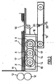
- the apparatus comprises a feed table 10 upon which a stack of sheets S may be placed against a gate 11 beneath which only the lowermost sheet in the stack may pass. Successive sheets are advanced beneath the gate 11 into the nip of take-up rolls 12 by a bed 13 of rollers 14 within the surface of the table.
- the take-up rolls 12 comprise an upper roll provided with tooling for appropriate treatment of the board, e.g. die cutting, slotting, creasing etc., and a lower roll which is also driven and may be provided with a layer of resiliently deformable material such as polyurethane, or contra tooling to the other roll, for engagement with the sheets as they travel through the nip between the rolls.
- the rollers 14 are mounted within a chamber 15 to which vacuum suction is applied to pull the lowermost sheet downwardly thereagainst.
- the rollers 14 advance the lowermost sheet by being rotatably driven as indicated by the arrows X at a speed equal to or less than the speed of the take-up rolls 12.
- the rollers 14 by virtue of having sprag clutches between their inner peripheries and their drive shafts 16 are arranged to free-wheel if the speed imparted to the sheet by the rolls exceeds that of the rollers 14.
- the drive to the rollers 14 may be reduced or arrested altogether according to circumstances. Under these conditions, the rollers 14 simply rotate by virtue of their contact with the sheet material as driven by the roll set 12.
- forward drive to the rollers 14 may be arrested and a vacuum chamber 30 behind the rollers 14 is exhausted to hold the next lowermost sheet in a fixed position against the action of the free-wheeling rollers after the sheet being fed has passed under the gate 11 to leave an opening through which the next sheet could otherwise prematurely pass.
- the chamber 30 can be exhausted continuously or cyclically.
- the drive shafts 16 are rotatably interconnected by timing drive belts 17 and one shaft is driven by a timing belt 18 itself driven intermittently in a forward direction only by a servo-electric motor 21 which may stop whilst a sheet is being advanced by the take-up rolls 12 and which operates at a timed sequence demanded by the processing machinery.
- rollers 14 associated with each drive shaft 16 are separated by spacing portions 14a which may be rotatably fast with the rollers. Adjacent sets of rollers staggered; however, in a modification the rollers in adjacent sets (and the spacing portions between them) may be aligned rather than staggered.
- FIG. 3 The arrangement of Figure 3 is generally similar, like parts being indicated by like reference numerals.
- the timing belt 18 is driven by a timing belt 19 reciprocated by an arm 20 operating in time with the processing machinery.
- the shafts 16 of the rollers 14 are driven in reverse direction during the time that the rollers 14 are free-wheeling.
- Drive mechanisms other than those shown in Figures 1 to 3 are possible, such as from a reciprocating cam imitating the movement of the arm 20 of Figure 3 .
- the restraint provided by the vacuum chamber 30 to prevent misfeed of the next lowermost sheet is supplemented by brake means for damping rotation of rollers 14 so that once the sheet being fed has clears each set of freewheeling rollers, their rotation is rapidly arrested to prevent any premature advance of the next lowermost sheet in the stack.
- the brake means 40 arrests the rollers once they are no longer driven by their engagement with the sheet being fed.
- the brake means 40 comprises friction pads or more elaborate mechanically or electrically or operable means for resisting rotation of the rollers 14.
- the brake means is arranged to constantly bear against the rollers or a component which rotates with the rollers when the latter are driven or when they freewheel.
- the contacting surfaces may be provided with material such as a PTFE which has sufficiently low friction to reduce wear while affording sufficient braking to prevent freewheeling once the rollers when this could otherwise affect accurate positioning of the blanks.
- a PTFE which has sufficiently low friction to reduce wear while affording sufficient braking to prevent freewheeling once the rollers when this could otherwise affect accurate positioning of the blanks.
- the roller arrangement of Figure 2 is modified in the manner previously described where the rollers 14 and the spacing portions 14a are aligned instead of being staggered, and the braking means comprises one or more arms (not illustrated in Figure 2 ) which each bridge and constantly bear against a respective set of aligned spacing portions 14a to arrest freewheeling thereof as soon as the rollers 14 are no longer driven by the sheet material.
- the vacuum chamber 30 may be dispensed with altogether and the necessary restraint to prevent misfeed of the next lowermost sheet by the freewheeling rollers may be provided solely by damping the freewheeling rollers 14, e.g. by means of the brake means 40.
- Figure 4 shows another aspect of the invention which is used together with, sheet or roller braking as described above.
- Those parts in Figure 4 having counterparts in Figures 1 and 2 are depicted by the same reference numerals and, insofar as they function in the same way as in the embodiment of Figures 1 and 2 , will not be described in detail below.
- the drive to the shafts 16 and hence the rollers 14 is provided by a servo-electric motor 21 which is operable to drive the rollers to effect forward feed of the sheets, one by one, to the rolls 12 but stops whilst a sheet is being advanced by the rolls 12, operation of the motor 21 being in a timed sequence demanded by the processing machinery.
- the servo-motor 21 is controlled by a microprocessor 50 which receives data from a pulsed shaft encoder 31 indicating the rotational position of the take-up rolls 12 and also from a sensing means comprising for example a high speed fibre optic sensor 32 located between the gate 11 and take-up rolls 12.
- the sensor 32 is arranged to detect passage of a datum on the sheet being fed, e.g. the leading edge of the sheet, a cut-out or a preselected printed mark on the sheet. Where the sensor detects a preselected printed mark, this may be specifically provided for the purpose during a preceding step of the sheet treatment process, e.g. on a section of the sheet which is to removed during die cutting, or it may be constituted by a specific sensor-identifiable location of a pre-printed area, e.g. an image or such like, on the sheet.
- the microprocessor 50 is programmed to control the servo-motor 21 to ensure that the sheet, e.g. the leading edge of the sheet, presents itself at the nip between the rolls 12 at precisely the correct instant and at a desired speed. It will be understood that the exact position of the leading edge or other datum of any sheet at the commencement of feed is immaterial since any variation is detected by the sensor and microprocessor 50 and can be compensated for by appropriate control of the servo-drive by the microprocessor to effect registry of the tooling on roll set 12 with the desired position on the blank..
- the brake means 40 of the embodiment of Figures 1 and 2 and the vacuum chamber 30 are incorporated to enhance control of sheet feed, thereby reducing the amount of correction which might otherwise be required by the microprocessor and servo-drive.
- the sensor and servo-drive control arrangement of Figure 4 may also be used in conjunction with a take-up mechanism in the form of gripper bars, in which event the microprocessor may be programmed to present the sheet, e.g. the leading edge thereof, to the gripper bars at the correct instant but at zero speed.
- a servo-drive affords the potential for significantly greater flexibility in the range of sheet or board sizes that can be handled by the sheet treatment machinery in that a given arrangement of tooling on the rolls 12 may be used for cutting, printing, creasing or scoring discrete blanks of sheet material which differ substantially in length and in particular blanks that may be longer than the circumference of the tool-carrying roll set.
- the tools will be referred to as slotting tools; however, they may equally be other types of tool such as sheet creasing tools.
- the smaller circle depicts the actual circumference of the upper roll 12 which is shown with four sets of tooling A, B, C and D, e.g. slotting tools, disposed at different locations around its periphery.
- a feeder as described with reference to Figure 4 is provided. Only feed rollers 14 are illustrated for simplicity.
- the tools A, B,C and D are illustrated as being equispaced around the circumference of roll 12 but this is purely by way of example and is not essential.
- the sheets S are fed to the nip N by the rollers 14 from right to left as arrowed and pass through the nip N between the upper and lower rolls 12 (the lower roll 12 being unshown in Figure 5 ) where contact is made with the tools as the rolls rotate and the board progresses through the nip.
- rollers 14 act as means for transmitting drive from the servomotor 21 (see Figure 4 ) to the sheets but, under conditions where under the control of the roll set 12 the sheet is travelling at a speed greater than the speed of rollers 14 at that instant, the latter freewheel while remaining in contact with the sheet being fed. Once the sheet being processed by the roll set 12 clears one or more of the rollers however, braking of the roller or rollers no longer in contact with the sheet occurs so that freewheeling is arrested substantially instantaneously.
- the sheet in Figure 5 is intended to be processed by the rolls in such a way as to slot the sheet at locations A1, B1, C1 and D1 which are spaced apart by distances corresponding to the spacings between the tools A, B, C and D.
- the sheet may therefore progress through the nip at substantially the same speed as the peripheral speed of the rolls 12.
- the slot at location A1 has already been produced and that portion of the sheet has advanced beyond the nip N.
- the slot B1 is in the process of production. Slots at locations C1 and D1 have yet to be produced.
- the slots A1, B1, C1 and D1 demarcate successive panels 1, 2, 3 and 4 and typically are each 400 mm in length, i.e. corresponding to a circumferential separation of 400 mm between the tools carried by upper roll 12.
- the sheet drive located upstream of the nip N is arranged to sheet feed not only to the nip but also participates in sheet feed through the nip, the arrangement being such that that sheet feed through the nip is only effected by rolls 12 primarily when one of the tools engages the sheet; at other times, except for the trailing section of the sheet (as described further below), sheet feed through the nip is effected by the upstream sheet drive.
- a feature of this aspect of the invention is the capability of transferring sheet drive between the servomotor 21 and the roll set 12 while the sheet is travelling through the nip.
- an embodiment in accordance with this aspect of the invention need not, at least not for the major length of the sheet, incorporate such sheet traction sections in addition to the tooling.
- each tool will initially engage with the sheet at a location slightly upstream of the nip N and finally disengage from the sheet at a location slightly downstream of the nip, the precise points of tool-sheet engagement and disengagement being dependent upon factors such as the radial extension of the tooling and the thickness of the sheet material.
- the sheet is fed through the nip N by the servomotor 21 (via rollers 14) during those phases of the treatment cycle when the tooling is not engaged with the sheet.
- the microcontroller 50 is programmed to regulate the servomotor speed. Through monitoring of the positional information derived from the encoder 31 and the sensor 32 coupled with information relating to the configuration of treatment operations to be performed on the sheet by the tooling , the microcontroller 50 serves to co-ordinate operation of the servomotor 21 with the roll set 12 in such a way the equipment is capable of handling a wide range of sheet lengths including lengths which signficantly exceed the circumference of the tool-carrying roll.
- the servomotor 21 will be effective to drive the sheet through the nip N in such a way that the slots B1, C1 and D1 are created at predetermined locations relative to the slot A1 by feeding the sheet through a distance equivalent to the distance between the tool-sheet disengagement and tool-sheet engagement.
- FIG. 6 shows a longer sheet size which is intended to be slotted at locations A2, B2, C2 and D2.
- panels 1 and 3 of the sheet illustrated in Figure 6 may have the same dimension (in the feed direction) as panels 1 and 3 in Figure 5 , e.g. 400 mm.
- panels 2 and 4 may be different, e.g. 1100 mm in length.
- the slotting configuration of the sheet in Figure 6 can be achieved using the same set of rolls 12 as used to produce the slotting configuration of Figure 5 by pre-programming the microprocessor with appropriate data relating to the Figure 6 configuration so that, during passage of those sheet lengths corresponding to panels 2 and 4 through the nip N, the sheet is accelerated by the servo-drive/rollers 14 to a speed significantly greater than the tangential speed of the rolls 12 thereby compensating for the fact that the spacing between the slotting tools is less than the length of sheet to be left untreated between successive tool operations thereon.
- the upper roll 12 will at times be equivalent to a virtual roll, depicted diagrammatically in Figure 5 by the circle referenced 12V, of much greater diameter than the actual roll 12.
- One possible speed profile imparted to the sheet is indicated diagrammatically in Figure 6 .
- curves 60 and 70 represent the increased speed profile for sheet feed as the panels 2 and 4 are fed through the nip N while lines lines 80 and 90 represent those intervals during which sheet feed is substantially the same as the tangential speed of the rolls 12.
- the microcontroller (having been primed with the relevant information relating to panel sizes) is programmed to control the servo-drive in such a way that the sheet speed profile during travel through the nip is adapted to compensate for the fact that the sheet is required to travel a shorter distance compared with the circumferential spacing between successive tools.
- the speed profile may for instance involve a dwell period in which the sheet is stationary.
- the speed profile for servo-driven feed of the sheet may be such that each time a tool approaches the sheet, the sheet speed is travelling at a speed greater than the roll speed but is progressively reduced to so that the sheet speed is marginally slower (typically by a factor of up to 5%, e.g. 2 to 3%) than roll speed immediately prior to transfer of drive from the servomotor to the rolls 12.
- the microcontroller causes the servomotor speed to increase again so that, at the point of tool-sheet engagement, the servomotor speed is substantially matched with the roll speed to effect smooth transfer of sheet feed back to the servomotor.
- the microcontroller may control the servomotor speed so that it is slightly slower than the tool speed immediately prior to such disengagement thereby allowing the freewheel action to effect such compensation.
- rollers 14 During the time that there is tool-sheet engagement, the rollers 14 will be freewheeling.
- the braking applied to the rollers 14 is designed prevent any tendency for over run to occur due to inertia at the time of transfer of drive back to the servomotor, which could otherwise result in the sheet getting out of registration with the tooling.
- the braking action exerted on the freewheeling rollers 14 is particularly important to prevent misregistration between the sheet passing through the nip and the tooling.
- the sensor 32 may be arranged to detect a number of strategically located datum positions on the sheet and feed back the information to the microcontroller so that, if any misregistration develops, this can be compensated for by appropriate control of the servomotor 21.
- the braking action is of lesser significance but may nevertheless be of advantage in limiting the extent of any misregistration that might otherwise occur through inertia-created over run of the rollers 14 when in freewheeling mode.
- sheet drive is transferred back to the servomotor.
- the rollers will not be capable of completing drive of the sheet through the nip. This may be catered for either by transfer of the sheet to a further drive downstream of the nip, i.e. to drive the trailing section of the sheet through the nip, or by providing the roll set with a strategically located traction section 66 (see Figure 5 ).
- a further drive may comprise a bed of rollers generally similar to the bed 13 of rollers 14 provided upstream of the nip N.
- the further set of rollers may be driven in exact synchronism with the upstream set of rollers, e.g. by using the same servo-drive 21 to drive both sets of rollers.
- the microcontroller may be programmed to accept user-entered adjustments to allow such variations to be compensated for. For example, after the microcontroller has been set up for a particular run, the operator may check the slotted sheets produced and, in the event of any offset from the desired slotting locations, may key in an adjustment via the input 52 so that the microcontroller can modify the sheet drive appropriately to remove the offset. This may be an interative process in practice - i.e. a number of samples may be checked with corresponding modification of the offset keyed into the microcontroller until the offset has been reduced or eliminated.
- the roll speed will normally be substantially constant; however the drive to the rolls 12 may be a variable speed drive so that roll speed may be increased or reduced for different productions runs (or even in the course of a particular production run).
- This allows greater flexibility in the lengths of sheet that can be handled. For instance, in the case of sheet which is to be produced with very large untreated panel sections, it may be desirable to operate at a lower roll speed (or even zero roll speed) while the tooling is out of engagement with the sheet material so as to afford more time for feed of long sections of the sheet by the servo-controlled drive.
- references to the roll set speed, the speed of the rollers 14 and the speed of the servomotor are to be construed in terms of the speed of travel of the sheet.
- the rolls 12 may include tooling for severing, e.g. by cross-cutting, the continuous web fed thereto into discrete sheets of length up to or exceeding the circumference of the tool-carrying roll or rolls.
- the rolls 12 may be provided with one or more circumferentially spaced tools for performing other operations on the web.
Landscapes
- Engineering & Computer Science (AREA)
- Mechanical Engineering (AREA)
- Sheets, Magazines, And Separation Thereof (AREA)
- Polishing Bodies And Polishing Tools (AREA)
- Delivering By Means Of Belts And Rollers (AREA)
- Cleaning Implements For Floors, Carpets, Furniture, Walls, And The Like (AREA)
- Making Paper Articles (AREA)
Abstract
Description
- This invention concerns apparatus use in the processing of sheet material, particularly, though by no means exclusively, of corrugated board or card as used in the box and carton making industries.
- The present invention is concerned with ensuring that feed of the sheet material is in proper registry with the sheet-treatment machinery.
- To this end prior known sheet feeding apparatus has relied upon the leading edge of each sheet being at a defined position at the commencement of feed. Many factors, including premature movement of a sheet by continuing rotation of feed rollers after the previously fed sheet has cleared them, mechanical tolerances, improper stacking of the sheets on the feed table, sheet quality and even atmospheric conditions can cause the leading edge of a sheet to be displaced from the expected defined position at the commencement of feed.
-
EP 0 521 158 relates to a sheet feed device with a sensor for detecting the forward end of a sheet driven by a conveyor and a control device responsive to the sensor for controlling the conveyor. The conveyor is controlled for two purposes. The first purpose is to synchronise the speed of the conveyor and a downstream print roller and the second purpose is correct the phasing of the sheet feed with a downstream print roller. It is directed to controlling the speed of the upstream drive and the print roller so that they operate at the same speed and is a system with no take-up mechanism because the print roller generates no drive to the sheet material. -
US4,941,517 relates to a method and apparatus for decollating stacked blanks in a feeding station for subsequent processing. A delivery conveyor is arranged under the stack of blanks for the controlled removal of the lowermost blank and for conveying the blank to a timed subsequent process. The transfer station of the subsequent process controls the speed of the delivery conveyor, which operates without fixed cycle. -
WO/96/29269 -
DE 196 40 963 A discloses an apparatus for feeding sheet material according to the preamble of claim 1 and a method of feeding sheet material according to the preamble ofclaim 15. - According to the present invention there is provided an apparatus for feeding sheet material having the features of claim 1 and a method of feeding sheet material having the features of
claim 15. - The datum on the sheet may be constituted by the leading edge of the sheet or some other suitably positioned mark on the sheet, e.g. printing previously applied to the sheet, a cut-out in the sheet or a print registration mark on the sheet. Prior to sheet treatment involving cutting and/or creasing for instance, it is common practice to apply printing to the sheet for product identification and/or advertising purposes and the subsequent sheet treatment has to be accurately registered with such printing. If the location of the printing is accurately positioned with the leading edge of the sheet and if the leading edge of the sheet has not been damaged in any way, then the leading edge may be used as the datum. However, if print position in relation to the leading edge is not consistent and/or if there is a possibility of the leading edge being damaged, then use of the printing itself as the datum source is to be preferred so that proper registry between the machinery tooling and the printed areas can be secured. Where the datum is derived from pre-applied printing on the sheet, it may be constituted for example by the a leading extremity of a selected part of the printed area.
- The microprocessor may also be programmed to ensure that the sheet, or at least the leading edge thereof, presents itself to the take-up mechanism at a desired speed.
- The desired speed may be substantially the same as but preferably is slightly less than the speed at which the take-up mechanism forwards the sheet. The desired speed may be substantially zero.
- In the invention, the means driven by the servo-motor may comprise a bed of rollers within the surface of the table which are rotatably driven to advance the lowermost sheet beneath the gate to the take-up mechanism and means to allow the rollers to free-wheel once the lowermost sheet is being advanced thereover by the take-up mechanism.
- These and various other aspects and features of the invention will be further apparent from the following description with reference to the figures of the accompanying drawings, in which:
-
Figure 1 shows a side elevation of a first form of feed apparatus; -
Figure 2 shows a cross-section through the apparatus on the line II-II ofFigure 1 ; -
Figure 3 shows a side elevation of a second form of feed apparatus; -
Figure 4 is a view similar to that ofFigure 1 showing the servo-drive for controlling positioning of the sheets; -
Figure 5 is a diagrammatic view of the invention in which sheet feed is shared between a servo-drive of the form illustrated inFigure 4 and the tool-carrying rolls for processsing the sheet; -
Figure 6 is a schematic view of a longer sheet than that shown inFigure 5 ; and - Referring now to
Figures 1 and 2 it will be seen that the apparatus comprises a feed table 10 upon which a stack of sheets S may be placed against agate 11 beneath which only the lowermost sheet in the stack may pass. Successive sheets are advanced beneath thegate 11 into the nip of take-up rolls 12 by a bed 13 ofrollers 14 within the surface of the table. The take-up rolls 12 comprise an upper roll provided with tooling for appropriate treatment of the board, e.g. die cutting, slotting, creasing etc., and a lower roll which is also driven and may be provided with a layer of resiliently deformable material such as polyurethane, or contra tooling to the other roll, for engagement with the sheets as they travel through the nip between the rolls. - The
rollers 14 are mounted within achamber 15 to which vacuum suction is applied to pull the lowermost sheet downwardly thereagainst. Therollers 14 advance the lowermost sheet by being rotatably driven as indicated by the arrows X at a speed equal to or less than the speed of the take-up rolls 12. Once the advance of sheet is under the control of therolls 12, therollers 14 by virtue of having sprag clutches between their inner peripheries and theirdrive shafts 16 are arranged to free-wheel if the speed imparted to the sheet by the rolls exceeds that of therollers 14. At this stage, the drive to therollers 14 may be reduced or arrested altogether according to circumstances. Under these conditions, therollers 14 simply rotate by virtue of their contact with the sheet material as driven by the roll set 12. - At least during this free-wheeling stage forward drive to the
rollers 14 may be arrested and avacuum chamber 30 behind therollers 14 is exhausted to hold the next lowermost sheet in a fixed position against the action of the free-wheeling rollers after the sheet being fed has passed under thegate 11 to leave an opening through which the next sheet could otherwise prematurely pass. Thechamber 30 can be exhausted continuously or cyclically. - The
drive shafts 16 are rotatably interconnected bytiming drive belts 17 and one shaft is driven by atiming belt 18 itself driven intermittently in a forward direction only by a servo-electric motor 21 which may stop whilst a sheet is being advanced by the take-up rolls 12 and which operates at a timed sequence demanded by the processing machinery. - In
Figure 2 , therollers 14 associated with eachdrive shaft 16 are separated byspacing portions 14a which may be rotatably fast with the rollers. Adjacent sets of rollers staggered; however, in a modification the rollers in adjacent sets (and the spacing portions between them) may be aligned rather than staggered. - The arrangement of
Figure 3 is generally similar, like parts being indicated by like reference numerals. In this embodiment, however, thetiming belt 18 is driven by atiming belt 19 reciprocated by anarm 20 operating in time with the processing machinery. Thus theshafts 16 of therollers 14 are driven in reverse direction during the time that therollers 14 are free-wheeling. Drive mechanisms other than those shown inFigures 1 to 3 are possible, such as from a reciprocating cam imitating the movement of thearm 20 ofFigure 3 . - Referring back to
Figure 1 , the restraint provided by thevacuum chamber 30 to prevent misfeed of the next lowermost sheet is supplemented by brake means for damping rotation ofrollers 14 so that once the sheet being fed has clears each set of freewheeling rollers, their rotation is rapidly arrested to prevent any premature advance of the next lowermost sheet in the stack. The brake means 40 arrests the rollers once they are no longer driven by their engagement with the sheet being fed. The brake means 40 comprises friction pads or more elaborate mechanically or electrically or operable means for resisting rotation of therollers 14. The brake means is arranged to constantly bear against the rollers or a component which rotates with the rollers when the latter are driven or when they freewheel. In this instance, the contacting surfaces may be provided with material such as a PTFE which has sufficiently low friction to reduce wear while affording sufficient braking to prevent freewheeling once the rollers when this could otherwise affect accurate positioning of the blanks. More specifically, after the departing sheet has cleared therollers 14, the latter are required to be substantially static with respect to the next sheet to be fed so that that sheet is not advanced by an indeterminate amount (thereby causing misregistration) as could otherwise happen if therollers 14 are allowed to over run upon disengagement with the previously fed sheet. Therollers 14 remain static until driven by theservomotor 21 when feed of the next sheet is required. - In one implementation of the braking means, the roller arrangement of
Figure 2 is modified in the manner previously described where therollers 14 and thespacing portions 14a are aligned instead of being staggered, and the braking means comprises one or more arms (not illustrated inFigure 2 ) which each bridge and constantly bear against a respective set of alignedspacing portions 14a to arrest freewheeling thereof as soon as therollers 14 are no longer driven by the sheet material. - In a further modification, the
vacuum chamber 30 may be dispensed with altogether and the necessary restraint to prevent misfeed of the next lowermost sheet by the freewheeling rollers may be provided solely by damping thefreewheeling rollers 14, e.g. by means of the brake means 40. - In the embodiments thus far described, misfeed through overrun of the freewheeling rollers is managed by braking the rollers and/or by braking the next lowermost sheet to be fed from the stack.
Figure 4 shows another aspect of the invention which is used together with, sheet or roller braking as described above. Those parts inFigure 4 having counterparts inFigures 1 and 2 are depicted by the same reference numerals and, insofar as they function in the same way as in the embodiment ofFigures 1 and 2 , will not be described in detail below. - In
Figure 4 , the drive to theshafts 16 and hence therollers 14 is provided by a servo-electric motor 21 which is operable to drive the rollers to effect forward feed of the sheets, one by one, to therolls 12 but stops whilst a sheet is being advanced by therolls 12, operation of themotor 21 being in a timed sequence demanded by the processing machinery. The servo-motor 21 is controlled by amicroprocessor 50 which receives data from apulsed shaft encoder 31 indicating the rotational position of the take-up rolls 12 and also from a sensing means comprising for example a high speed fibreoptic sensor 32 located between thegate 11 and take-up rolls 12. - The
sensor 32 is arranged to detect passage of a datum on the sheet being fed, e.g. the leading edge of the sheet, a cut-out or a preselected printed mark on the sheet. Where the sensor detects a preselected printed mark, this may be specifically provided for the purpose during a preceding step of the sheet treatment process, e.g. on a section of the sheet which is to removed during die cutting, or it may be constituted by a specific sensor-identifiable location of a pre-printed area, e.g. an image or such like, on the sheet. - The
microprocessor 50 is programmed to control the servo-motor 21 to ensure that the sheet, e.g. the leading edge of the sheet, presents itself at the nip between therolls 12 at precisely the correct instant and at a desired speed. It will be understood that the exact position of the leading edge or other datum of any sheet at the commencement of feed is immaterial since any variation is detected by the sensor andmicroprocessor 50 and can be compensated for by appropriate control of the servo-drive by the microprocessor to effect registry of the tooling on roll set 12 with the desired position on the blank.. - According to the invention, and as shown in
Figure 4 , where misfeed of the lowermost sheet can be compensated for by the sensor and servo-drive arrangement, the brake means 40 of the embodiment ofFigures 1 and 2 and the vacuum chamber 30 (not shown infigure 4 ) are incorporated to enhance control of sheet feed, thereby reducing the amount of correction which might otherwise be required by the microprocessor and servo-drive. - The sensor and servo-drive control arrangement of
Figure 4 may also be used in conjunction with a take-up mechanism in the form of gripper bars, in which event the microprocessor may be programmed to present the sheet, e.g. the leading edge thereof, to the gripper bars at the correct instant but at zero speed. - We have found that the use of a servo-drive, as shown in
Figure 4 , affords the potential for significantly greater flexibility in the range of sheet or board sizes that can be handled by the sheet treatment machinery in that a given arrangement of tooling on therolls 12 may be used for cutting, printing, creasing or scoring discrete blanks of sheet material which differ substantially in length and in particular blanks that may be longer than the circumference of the tool-carrying roll set. In the following description, for simplicity the tools will be referred to as slotting tools; however, they may equally be other types of tool such as sheet creasing tools. - Referring to
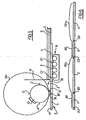
Figure 5 , the smaller circle depicts the actual circumference of theupper roll 12 which is shown with four sets of tooling A, B, C and D, e.g. slotting tools, disposed at different locations around its periphery. Upstream of therolls 12, a feeder as described with reference toFigure 4 is provided. Only feedrollers 14 are illustrated for simplicity. - The tools A, B,C and D are illustrated as being equispaced around the circumference of
roll 12 but this is purely by way of example and is not essential. The sheets S are fed to the nip N by therollers 14 from right to left as arrowed and pass through the nip N between the upper and lower rolls 12 (thelower roll 12 being unshown inFigure 5 ) where contact is made with the tools as the rolls rotate and the board progresses through the nip. It will be understood that therollers 14 act as means for transmitting drive from the servomotor 21 (seeFigure 4 ) to the sheets but, under conditions where under the control of the roll set 12 the sheet is travelling at a speed greater than the speed ofrollers 14 at that instant, the latter freewheel while remaining in contact with the sheet being fed. Once the sheet being processed by the roll set 12 clears one or more of the rollers however, braking of the roller or rollers no longer in contact with the sheet occurs so that freewheeling is arrested substantially instantaneously. - The sheet in
Figure 5 is intended to be processed by the rolls in such a way as to slot the sheet at locations A1, B1, C1 and D1 which are spaced apart by distances corresponding to the spacings between the tools A, B, C and D. The sheet may therefore progress through the nip at substantially the same speed as the peripheral speed of therolls 12. As illustrated, the slot at location A1 has already been produced and that portion of the sheet has advanced beyond the nip N. The slot B1 is in the process of production. Slots at locations C1 and D1 have yet to be produced. The slots A1, B1, C1 and D1 demarcatesuccessive panels upper roll 12. - In accordance with one of the aspects of the present invention, the sheet drive located upstream of the nip N is arranged to sheet feed not only to the nip but also participates in sheet feed through the nip, the arrangement being such that that sheet feed through the nip is only effected by
rolls 12 primarily when one of the tools engages the sheet; at other times, except for the trailing section of the sheet (as described further below), sheet feed through the nip is effected by the upstream sheet drive. A feature of this aspect of the invention is the capability of transferring sheet drive between theservomotor 21 and the roll set 12 while the sheet is travelling through the nip. In this regard, in contrast with conventional roll sets which are provided with sheet traction sections for driving the sheet when not engaged with the tooling, an embodiment in accordance with this aspect of the invention need not, at least not for the major length of the sheet, incorporate such sheet traction sections in addition to the tooling. - For a given production run, the
rolls 12 will normally rotate at constant peripheral speed with the consequence that each tool will, in the direction of sheet travel, have a well-defined linear velocity the instant it registers with the dead centre position of the nip N. In practice, each tool will initially engage with the sheet at a location slightly upstream of the nip N and finally disengage from the sheet at a location slightly downstream of the nip, the precise points of tool-sheet engagement and disengagement being dependent upon factors such as the radial extension of the tooling and the thickness of the sheet material. Except for the trailing section of the sheet, in the embodiment ofFigure 5 the sheet is fed through the nip N by the servomotor 21 (via rollers 14) during those phases of the treatment cycle when the tooling is not engaged with the sheet. To achieve this, themicrocontroller 50 is programmed to regulate the servomotor speed. Through monitoring of the positional information derived from theencoder 31 and thesensor 32 coupled with information relating to the configuration of treatment operations to be performed on the sheet by the tooling , themicrocontroller 50 serves to co-ordinate operation of theservomotor 21 with the roll set 12 in such a way the equipment is capable of handling a wide range of sheet lengths including lengths which signficantly exceed the circumference of the tool-carrying roll. - Thus, in the case of the sheet undergoing slotting in
Figure 5 , theservomotor 21 will be effective to drive the sheet through the nip N in such a way that the slots B1, C1 and D1 are created at predetermined locations relative to the slot A1 by feeding the sheet through a distance equivalent to the distance between the tool-sheet disengagement and tool-sheet engagement. - Because sheet feed through the nip N is primarily under the control of the servo-drive rather than the
rolls 12, it is possible to cater for different cutting regimes using a roll set 12 of given circumferential dimensions. For example,Figure 6 shows a longer sheet size which is intended to be slotted at locations A2, B2, C2 and D2. Purely by way of example,panels 1 and 3 of the sheet illustrated inFigure 6 may have the same dimension (in the feed direction) aspanels 1 and 3 inFigure 5 , e.g. 400 mm. However,panels 2 and 4 may be different, e.g. 1100 mm in length. The slotting configuration of the sheet inFigure 6 can be achieved using the same set ofrolls 12 as used to produce the slotting configuration ofFigure 5 by pre-programming the microprocessor with appropriate data relating to theFigure 6 configuration so that, during passage of those sheet lengths corresponding topanels 2 and 4 through the nip N, the sheet is accelerated by the servo-drive/rollers 14 to a speed significantly greater than the tangential speed of therolls 12 thereby compensating for the fact that the spacing between the slotting tools is less than the length of sheet to be left untreated between successive tool operations thereon. - In effect, the
upper roll 12 will at times be equivalent to a virtual roll, depicted diagrammatically inFigure 5 by the circle referenced 12V, of much greater diameter than theactual roll 12. One possible speed profile imparted to the sheet is indicated diagrammatically inFigure 6 . Thus, curves 60 and 70 represent the increased speed profile for sheet feed as thepanels 2 and 4 are fed through the nip N while lines lines 80 and 90 represent those intervals during which sheet feed is substantially the same as the tangential speed of therolls 12. - It will be appreciated that when one or more of the panels is required to be shorter than the circumferential spacing between successive tools, the microcontroller (having been primed with the relevant information relating to panel sizes) is programmed to control the servo-drive in such a way that the sheet speed profile during travel through the nip is adapted to compensate for the fact that the sheet is required to travel a shorter distance compared with the circumferential spacing between successive tools. The speed profile may for instance involve a dwell period in which the sheet is stationary.
- In practice, irrespective of the lengths of the panel sections relative to the circumferential spacings of the tools, the speed profile for servo-driven feed of the sheet may be such that each time a tool approaches the sheet, the sheet speed is travelling at a speed greater than the roll speed but is progressively reduced to so that the sheet speed is marginally slower (typically by a factor of up to 5%, e.g. 2 to 3%) than roll speed immediately prior to transfer of drive from the servomotor to the
rolls 12. This allows the freewheel action to come into play thereby compensating for any line speed differential between the servo-drive 21 and the rolls and substantially reducing or eliminating any tendency for the sheet material to scuff or scrub the polyurethane surface of the lower roll which would thereby necessitate frequent replacement of the polyurethane. The instant that drive transfer from theservomotor 21 to therolls 12 occurs, the tooling will be travelling faster than the sheet. Therollers 14 are thus caused to freewheel and will, in effect, turn through a well-defined angular distance corresponding to the length of sheet fed while the sheet is being driven by therolls 12. At this time, the microcontroller may be progrrammed to slow down the servomotor or even stop it altogether. As the point of tool-sheet disenagement approaches, the microcontroller causes the servomotor speed to increase again so that, at the point of tool-sheet engagement, the servomotor speed is substantially matched with the roll speed to effect smooth transfer of sheet feed back to the servomotor. To compensate for any line speed differential at the time of tool-sheet disengagement, the microcontroller may control the servomotor speed so that it is slightly slower than the tool speed immediately prior to such disengagement thereby allowing the freewheel action to effect such compensation. - During the time that there is tool-sheet engagement, the
rollers 14 will be freewheeling. The braking applied to therollers 14 is designed prevent any tendency for over run to occur due to inertia at the time of transfer of drive back to the servomotor, which could otherwise result in the sheet getting out of registration with the tooling. - If the
sensor 32 is arranged to detect only one datum position on the sheet (e.g. the leading edge or a predetermined point in a printed image), the braking action exerted on thefreewheeling rollers 14 is particularly important to prevent misregistration between the sheet passing through the nip and the tooling. However, thesensor 32 may be arranged to detect a number of strategically located datum positions on the sheet and feed back the information to the microcontroller so that, if any misregistration develops, this can be compensated for by appropriate control of theservomotor 21. In this case, the braking action is of lesser significance but may nevertheless be of advantage in limiting the extent of any misregistration that might otherwise occur through inertia-created over run of therollers 14 when in freewheeling mode. - After the final tool disengages the sheet during treatment of a particular sheet, sheet drive is transferred back to the servomotor. However, because there is necessarily a gap between the
rollers 14 and the nip N, the rollers will not be capable of completing drive of the sheet through the nip. This may be catered for either by transfer of the sheet to a further drive downstream of the nip, i.e. to drive the trailing section of the sheet through the nip, or by providing the roll set with a strategically located traction section 66 (seeFigure 5 ). Where a further drive is provided downstream for this purpose, it may comprise a bed of rollers generally similar to the bed 13 ofrollers 14 provided upstream of the nip N. In this event, the further set of rollers may be driven in exact synchronism with the upstream set of rollers, e.g. by using the same servo-drive 21 to drive both sets of rollers. - It will be understood that, for a given roll set and tooling arrangement, wide variations in sheet slotting (or printing/creasing/scoring) configuration and sheet length may be catered for by appropriate programming of the microcontroller. Thus, in practice, once the microprocessor has been programmed for a number of predetermined slotting configurations, the process may be carried out simply by inputting, for a given run, the particular slotting configuration required and the required dimensions. Thus, a user entry input 52 (see
Figure 4 ) may be provided for entry of the relevant data into themicrocontroller 50. User input may be menu driven; for instance, there may be a dislay monitor on which the selected slotting configuration is displayed with an invitation for the user to key in dimensions for each panel section. - The precise points of drive transfer from the
rolls 12 to theservomotor 21 and vice versa may not be accurately predictable in advance because of variations in sheet thickness, humidity conditions, radial tool dimensions and settings etc. In order to cater for this, the microcontroller may be programmed to accept user-entered adjustments to allow such variations to be compensated for. For example, after the microcontroller has been set up for a particular run, the operator may check the slotted sheets produced and, in the event of any offset from the desired slotting locations, may key in an adjustment via theinput 52 so that the microcontroller can modify the sheet drive appropriately to remove the offset. This may be an interative process in practice - i.e. a number of samples may be checked with corresponding modification of the offset keyed into the microcontroller until the offset has been reduced or eliminated. - During the course of a given production run, the roll speed will normally be substantially constant; however the drive to the
rolls 12 may be a variable speed drive so that roll speed may be increased or reduced for different productions runs (or even in the course of a particular production run). This allows greater flexibility in the lengths of sheet that can be handled. For instance, in the case of sheet which is to be produced with very large untreated panel sections, it may be desirable to operate at a lower roll speed (or even zero roll speed) while the tooling is out of engagement with the sheet material so as to afford more time for feed of long sections of the sheet by the servo-controlled drive. - For the avoidance of doubt, as used herein, except where the context admits otherwise, references to the roll set speed, the speed of the
rollers 14 and the speed of the servomotor are to be construed in terms of the speed of travel of the sheet. - Although the invention is described above with reference primarily to the treatment of blanks of sheet material, the possibility is not excluded of feeding a continuous web of material to the
rolls 12 and controlling web passage through the nip in the manner described above. Thus, for example, therolls 12 may include tooling for severing, e.g. by cross-cutting, the continuous web fed thereto into discrete sheets of length up to or exceeding the circumference of the tool-carrying roll or rolls. In addition to the severing tool, therolls 12 may be provided with one or more circumferentially spaced tools for performing other operations on the web.
Claims (18)
- Apparatus for feeding sheet material (S) sequentially on demand to a take-up mechanism of sheet processing machinery, said apparatus comprising a servo-drive motor (21), means for transmitting drive from the servo-drive motor to the sheet material to advance the sheet material to the take-up mechanism, sensing means (32) for detecting the passage of a datum position of the sheet material as the latter advances towards the take-up mechanism, wherein said take-up mechanism comprises a pair of take up rolls (12) and said apparatus further comprises a microprocessor (50) which receives data indicating the position of the take up rolls and from the sensing means and programmed to control the seryo-drive motor to secure registration between the sheet material and the take-up rolls, characterized in that said drive transmitting means comprises rollers (14) which engage the sheet material; and in that said apparatus further comprises brake means (40) comprising friction pads or more elaborate mechanically or electrically operable means for restricting rotation of the rollers (14) and arranged to constantly bear against the rollers or a component which rotates with the rollers when the rollers are driven or when they freewheel, the arrangement being such that, when the take up rolls (12) commence to feed the sheet, the rollers (14) operate automatically in a freewheel mode while in engagement with the sheet material travelling at a speed greater than the speed of the servo motor drive and the brake means (40) substantially instantaneously arrests the rotation of the rollers (14) once the sheet being processed by the take up rolls (12) clears one or more of the rollers (14) by braking or damping of the roller or rollers no longer in contact with the sheet.
- Apparatus according to claim 1 additionally comprising a feed table (10) having a gate (11) and upon which sheets (S) may be stacked against the gate, which allows only the lowermost sheet to pass beneath the gate to the take-up mechanism.
- Apparatus according to claim 1 or 2 wherein the microprocessor (50) is programmed to ensure that the leading edge of the sheet (S) presents itself to the take-up rolls (12) at a desired speed.
- Apparatus according to claim 3 wherein the desired speed is slightly less than the speed at which the take-up rolls (12) forwards the sheet (S).
- Apparatus according to claim 3 wherein the desired speed is zero.
- Apparatus according to any one of the preceding claims in which said take-up rolls (12) are provided with one or more sheet-processing tools (A, B, C, D) for engagement with, and for imparting drive to, the sheet material (S) in a nip zone (N) between the roll set (12) and further comprising a first drive for rotating the roll set so that the sheet material is driven through the nip while engaged by the set(s) of tooling, a second drive including said servomotor (106) upstream of the nip zone for effecting feed of the sheet material, and means (108) operable to co-ordinate operation of the second drive with rotation of the roll set in such a way that sheet feed through and beyond the nip zone is effected in part by the roll set and in part by the second drive.
- Apparatus as claimed in claim 6 in which the feed of sheet material through the nip zone is effected by the roll set (12) at least while there is tool-sheet engagement.
- Apparatus as claimed in claim 6 or 7 in which feed of sheet material through the nip zone (N) is effected by the second drive (108) at least for part of the time that there is no tool-sheet engagement.
- Apparatus as claimed in any one of claims 1 and 6 to 8 in which the roll set (12) is provided with two or more circumferentially spaced sheet-processing tools (A, B, C, D).
- Apparatus as claimed in claim 9 in which the roll set (12) is provided with a traction section trailing one of the tools (A, B, C, D) for imparting feed motion to the sheet material (S) subsequent to disengagement between said one tool and the sheet.
- Apparatus as claimed in any one of claims 6 to 10 in which the second drive (106) is a variable speed drive operable to vary the speed profile of sheet material (S) feed through the nip zone (N).
- Apparatus as claimed in any one of claims 6 to 11 in which, during roll driven sheet material feed, the second drive (106) is arrested or operates at a reduced drive speed compared with the roll drive speed.
- Apparatus as claimed in any one of claims 6 to 12 in which, immediately prior to transfer of sheet material feed from the second drive to the roll set or vice versa, the second drive (106) is programmed to run at a speed which is reduced compared with the roll speed.
- Apparatus as claimed in any one of claims 6 to 12 in which, during the interval leading up to transfer of sheet material feed from the second drive (106) to the roll set (12) or vice versa, the second drive operates in a mode in which its speed exceeds the roll speed and is then adjusted to a lower speed.
- A method of feeding sheet material sequentially on demand to a pair of take up rolls of sheet processing machinery, comprising the steps of: transmitting drive using a drive transmitting means from a servo-drive motor (21) to the sheet material (S) to advance the sheet material to the take up rolls (12), detecting with a sensing means (32) the passage of a datum position of the sheet material as the latter advances towards the take up rolls, wherein the method comprises the following steps: taking up the sheet material using the take up rolls, receiving at a microprocessor (50) data indicating the position of the take-up rolls and from the sensing means, controlling with the microprocessor the servo-drive motor to secure registration between the sheet material and the take up rolls characterized in that the drive transmitting means comprises rollers (14) which engage the sheet material and in that the method further comprises the steps of when the take-up rolls commence to feed the sheet, operating the rollers (14) automatically in a freewheel mode while in engagement with the sheet material travelling at a speed greater than the speed of the servo-motor drive and arresting substantially instantaneously the rotation of the rollers (14) once the sheet material being processed by the take-up rolls (12) clears one or more of the rollers (14) by braking or damping of the roller or rollers no longer in contact with the sheet; wherein the braking or damping is provided by brake means (40) comprising friction pads or more elaborate mechanically or electrically operable means for restricting rotation of the rollers (14) and arranged to constantly bear against the rollers or a component that rotates with the rollers when the rollers are driven or when they freewheel.
- Method according to claim 15 comprising the step of ensuring by programming of the microprocessor (50) that the leading edge of the sheet presents itself to the take-up rolls at a desired speed.
- Method according to claim 16 wherein the desired speed is slightly less than the speed at which the take-up rollers forward the sheet.
- Method according to claim 17 wherein the desired speed is zero.
Applications Claiming Priority (7)
| Application Number | Priority Date | Filing Date | Title |
|---|---|---|---|
| WOPCT/GB99/01010 | 1999-03-31 | ||
| PCT/GB1999/001010 WO2000058190A1 (en) | 1999-03-31 | 1999-03-31 | Apparatus for feeding sheet material |
| PCT/GB1999/002040 WO2001000514A1 (en) | 1999-06-29 | 1999-06-29 | Apparatus for feeding sheet material |
| WOPCT/GB99/02040 | 1999-06-29 | ||
| GBGB9916159.8A GB9916159D0 (en) | 1999-07-10 | 1999-07-10 | Apparatus for feeding sheet material |
| GB9916159 | 1999-07-10 | ||
| EP00912798A EP1165418B1 (en) | 1999-03-31 | 2000-03-24 | Sheet material processing |
Related Parent Applications (1)
| Application Number | Title | Priority Date | Filing Date |
|---|---|---|---|
| EP00912798A Division EP1165418B1 (en) | 1999-03-31 | 2000-03-24 | Sheet material processing |
Publications (3)
| Publication Number | Publication Date |
|---|---|
| EP1424298A2 EP1424298A2 (en) | 2004-06-02 |
| EP1424298A3 EP1424298A3 (en) | 2004-09-22 |
| EP1424298B1 true EP1424298B1 (en) | 2010-01-13 |
Family
ID=56289899
Family Applications (2)
| Application Number | Title | Priority Date | Filing Date |
|---|---|---|---|
| EP04004626A Expired - Lifetime EP1424298B1 (en) | 1999-03-31 | 2000-03-24 | Sheet material processing |
| EP00912798A Expired - Lifetime EP1165418B1 (en) | 1999-03-31 | 2000-03-24 | Sheet material processing |
Family Applications After (1)
| Application Number | Title | Priority Date | Filing Date |
|---|---|---|---|
| EP00912798A Expired - Lifetime EP1165418B1 (en) | 1999-03-31 | 2000-03-24 | Sheet material processing |
Country Status (9)
| Country | Link |
|---|---|
| US (2) | US6829969B1 (en) |
| EP (2) | EP1424298B1 (en) |
| JP (2) | JP2002540041A (en) |
| AT (2) | ATE455066T1 (en) |
| AU (1) | AU3444400A (en) |
| DE (1) | DE60012159T2 (en) |
| ES (1) | ES2222187T3 (en) |
| GB (2) | GB2363603B (en) |
| WO (2) | WO2000058190A1 (en) |
Families Citing this family (18)
| Publication number | Priority date | Publication date | Assignee | Title |
|---|---|---|---|---|
| WO2000058190A1 (en) | 1999-03-31 | 2000-10-05 | John Anthony Sullivan | Apparatus for feeding sheet material |
| GB0026821D0 (en) * | 2000-11-02 | 2000-12-20 | Esselte Nv | Laminating machine |
| WO2002042189A2 (en) * | 2000-11-21 | 2002-05-30 | John Anthony Sullivan | Method and apparatus for feeding sheets |
| DE10137390B4 (en) | 2001-07-31 | 2013-06-13 | Giesecke & Devrient Gmbh | Method and device for the separation of sheet material |
| ITTO20011043A1 (en) * | 2001-11-02 | 2003-05-02 | Tetra Laval Holdings E Finance | SHEET PACKAGING MATERIAL FOR THE PACKAGING OF VERSABLE FOOD PRODUCTS. |
| DE102005023618B3 (en) * | 2005-05-21 | 2006-12-07 | Aci-Ecotec Gmbh & Co.Kg | Device for separating silicon wafers from a stack |
| US7635124B2 (en) * | 2005-12-28 | 2009-12-22 | Sun Automation, Inc. | Feeder with adjustable time cycle and method |
| FR2908757B1 (en) * | 2006-11-16 | 2009-02-13 | Neopost Technologies Sa | DEVICE FOR STACKING MAIL ITEMS. |
| CN101209600B (en) * | 2006-12-27 | 2010-05-19 | 上海今昌纸箱机械制造有限公司 | Paper feeding conveying mechanism with servo system |
| CN101935959B (en) * | 2010-08-09 | 2012-12-05 | 青岛美光机械有限公司 | Servo side pressing and paper feeding machine |
| DE102011116365A1 (en) * | 2011-10-19 | 2013-04-25 | Heidelberger Druckmaschinen Aktiengesellschaft | Sheet processing machine with sheet feeder with suction belt module |
| ES2561884T3 (en) * | 2012-07-18 | 2016-03-01 | Ardagh Mp Group Netherlands B.V. | Embossing on a flat metal starting piece (procedure and device) |
| US8748769B2 (en) * | 2012-10-24 | 2014-06-10 | Pitney Bowes Inc. | Stacking assembly for a mailpiece sorter |
| FR3000917B1 (en) * | 2013-01-11 | 2015-02-20 | Bobst Lyon | CONTROL METHOD FOR CONTROLLING A TRANSFORMING MACHINE, TRANSFORMING MACHINE AND COMPUTER PROGRAM FOR CARRYING OUT SUCH A CONTROL METHOD |
| TWI551533B (en) * | 2015-05-26 | 2016-10-01 | 住華科技股份有限公司 | Automatic apparatus for taking sheet and method for automatically taking sheet using the same |
| DE102016115049B3 (en) * | 2016-08-12 | 2018-02-15 | Troester Gmbh & Co. Kg | Device for feeding an extruder |
| DE102018133451B4 (en) * | 2018-12-21 | 2023-12-28 | Bdt Media Automation Gmbh | Holding device and method for operating a holding device |
| US11325799B2 (en) * | 2019-09-13 | 2022-05-10 | Xerox Corporation | Interdigitated vacuum roll system for a cut sheet printer dryer transport |
Family Cites Families (31)
| Publication number | Priority date | Publication date | Assignee | Title |
|---|---|---|---|---|
| GB756357A (en) | 1953-07-14 | 1956-09-05 | Bowaters Dev & Res Ltd | Severing means in web feeding machines |
| GB1385053A (en) | 1972-01-18 | 1975-02-26 | Masson Scott Thrissell Eng Ltd | Rotary drive controls |
| CH565697A5 (en) * | 1973-02-28 | 1975-08-29 | Bobst Fils Sa J | |
| US4131273A (en) * | 1977-05-13 | 1978-12-26 | Oce-Industries Inc. | Record card feeding apparatus |
| GB2042961B (en) * | 1979-02-20 | 1982-09-22 | Masson Scott Thrissell Eng Ltd | Cutting apparatus for continuous webs |
| US4529187A (en) * | 1982-09-17 | 1985-07-16 | International Telephone & Telegraph Corporation | Ticket magazine |
| JPS59177227A (en) * | 1983-03-24 | 1984-10-06 | Nec Corp | Paper-sheet feeding apparatus |
| JPS6125340U (en) | 1984-07-20 | 1986-02-15 | 三菱重工業株式会社 | Sheet feeding device |
| DE3542923A1 (en) * | 1985-12-04 | 1987-06-11 | Windmoeller & Hoelscher | DEVICE FOR SEPARATING SECTIONS FROM A RAILWAY BY CROSS-SEPARATING CUTTINGS IN ACCORDANCE WITH PRINTING MARKS ON THE RAILWAY |
| JPS6397566A (en) * | 1986-10-13 | 1988-04-28 | Tokyo Kikai Seisakusho Ltd | Automatic adjuster for paper sheet cutting position in rotary press machine |
| DE3640896A1 (en) * | 1986-11-29 | 1988-06-16 | Eckold Vorrichtung | METHOD AND DEVICE FOR RIVETLY JOINING SHEETS |
| US5184811A (en) * | 1988-10-13 | 1993-02-09 | Sun Automation, Inc. | Method and apparatus for feeding sheets |
| GB8901055D0 (en) * | 1989-01-18 | 1989-03-15 | Simon Container Mach Ltd | Apparatus for feeding boards or sheets from a stack |
| DE69025824T2 (en) | 1989-08-23 | 1996-09-26 | Rengo Co Ltd | Paper or cardboard box feeder and its control |
| JP2535428B2 (en) * | 1990-04-13 | 1996-09-18 | エス・ケイエンジニアリング株式会社 | Sheet supply device |
| US5172898A (en) * | 1990-07-05 | 1992-12-22 | Mitsubishi Jukogyo Kabushiki Kaisha | Paperboard feeding apparatus |
| US5241884A (en) * | 1991-10-11 | 1993-09-07 | F. L. Smithe Machine Company, Inc. | Apparatus for changing the length of envelope blanks cut from a continuous web |
| JP3093431B2 (en) | 1992-04-30 | 2000-10-03 | 株式会社リコー | Paper feeder of image forming device |
| DE4329124A1 (en) | 1993-08-30 | 1995-03-02 | Heidelberger Druckmasch Ag | Apparatus for supplying sheets in a feeder of a printing machine |
| US5397107A (en) | 1993-11-29 | 1995-03-14 | Pitney Bowes Inc. | Apparatus for separating and feeding sheets from a stack thereof |
| ITBO940267A1 (en) | 1994-06-07 | 1995-12-07 | Gd Spa | BLANK FEEDING UNIT. |
| GB9505616D0 (en) * | 1995-03-21 | 1995-05-10 | Sullivan John A | Apparatus for feeding sheet material |
| JPH08268583A (en) * | 1995-03-31 | 1996-10-15 | Isowa Corp | Rotation control method and device of feed roller in paper feeder |
| FR2738807B1 (en) | 1995-09-18 | 1997-12-05 | Rapidex Sm | SHEET FEEDING DEVICE IN A SHEET PROCESSING LINE |
| JP2000501999A (en) * | 1995-12-18 | 2000-02-22 | ワシュー パトリック | Paper cutter for variable format |
| DE19640963A1 (en) | 1996-10-04 | 1998-04-16 | Wolfgang Heiber | Preform feed mechanism for cartons |
| JPH1179445A (en) * | 1997-09-12 | 1999-03-23 | Isowa Corp | Sheet feeding device for sheet-shaped material |
| DE19756395B4 (en) * | 1997-12-18 | 2008-05-15 | WINKLER + DüNNEBIER AG | Device and method for separating material web sections from a moving, endless web in accordance with printed marks applied to the web, in particular for severing envelope blanks from a printed paper web |
| WO2000058190A1 (en) | 1999-03-31 | 2000-10-05 | John Anthony Sullivan | Apparatus for feeding sheet material |
| US6109604A (en) * | 1999-04-07 | 2000-08-29 | Macro Technology International Inc. | Media feeder |
| AU4524399A (en) | 1999-06-29 | 2001-01-31 | John Anthony Sullivan | Apparatus for feeding sheet material |
-
1999
- 1999-03-31 WO PCT/GB1999/001010 patent/WO2000058190A1/en active Application Filing
-
2000
- 2000-03-24 DE DE60012159T patent/DE60012159T2/en not_active Expired - Fee Related
- 2000-03-24 EP EP04004626A patent/EP1424298B1/en not_active Expired - Lifetime
- 2000-03-24 GB GB0117203A patent/GB2363603B/en not_active Expired - Fee Related
- 2000-03-24 AU AU34444/00A patent/AU3444400A/en not_active Abandoned
- 2000-03-24 GB GB0314403A patent/GB2387168B/en not_active Expired - Fee Related
- 2000-03-24 AT AT04004626T patent/ATE455066T1/en not_active IP Right Cessation
- 2000-03-24 US US09/936,917 patent/US6829969B1/en not_active Expired - Fee Related
- 2000-03-24 WO PCT/GB2000/001129 patent/WO2000058192A2/en active IP Right Grant
- 2000-03-24 ES ES00912798T patent/ES2222187T3/en not_active Expired - Lifetime
- 2000-03-24 EP EP00912798A patent/EP1165418B1/en not_active Expired - Lifetime
- 2000-03-24 AT AT00912798T patent/ATE271008T1/en not_active IP Right Cessation
- 2000-03-24 JP JP2000607906A patent/JP2002540041A/en active Pending
-
2004
- 2004-10-25 US US10/972,998 patent/US7192024B2/en not_active Expired - Fee Related
-
2008
- 2008-01-18 JP JP2008008830A patent/JP2008143715A/en active Pending
Also Published As
| Publication number | Publication date |
|---|---|
| DE60012159T2 (en) | 2005-08-04 |
| ES2222187T3 (en) | 2005-02-01 |
| EP1424298A2 (en) | 2004-06-02 |
| EP1165418A2 (en) | 2002-01-02 |
| WO2000058190A1 (en) | 2000-10-05 |
| GB2363603A (en) | 2002-01-02 |
| WO2000058192B1 (en) | 2001-04-12 |
| EP1424298A3 (en) | 2004-09-22 |
| ATE271008T1 (en) | 2004-07-15 |
| US20050056991A1 (en) | 2005-03-17 |
| GB0314403D0 (en) | 2003-07-23 |
| GB2387168B (en) | 2004-02-25 |
| JP2008143715A (en) | 2008-06-26 |
| GB2363603B (en) | 2003-10-08 |
| WO2000058192A2 (en) | 2000-10-05 |
| GB2387168C (en) | 1900-01-01 |
| ATE455066T1 (en) | 2010-01-15 |
| EP1165418B1 (en) | 2004-07-14 |
| US6829969B1 (en) | 2004-12-14 |
| DE60012159D1 (en) | 2004-08-19 |
| US7192024B2 (en) | 2007-03-20 |
| WO2000058192A3 (en) | 2001-02-15 |
| AU3444400A (en) | 2000-10-16 |
| GB0117203D0 (en) | 2001-09-05 |
| JP2002540041A (en) | 2002-11-26 |
| GB2387168A (en) | 2003-10-08 |
Similar Documents
| Publication | Publication Date | Title |
|---|---|---|
| EP1424298B1 (en) | Sheet material processing | |
| EP0615941B1 (en) | Sheet registration control | |
| JP4976833B2 (en) | Sheet material supply device and method | |
| US5006042A (en) | Apparatus for feeding boards or sheets from a stack | |
| US5606913A (en) | Sheet registration control | |
| SU1303023A3 (en) | Device for feeding marked strip material | |
| WO2017021886A1 (en) | Methods for creasing and cutting sheet materials | |
| JP3824997B2 (en) | Apparatus and method for sheet alignment | |
| KR101250039B1 (en) | Apparatus for decelerating sheets to be stacked, especially paper or cardboard sheets | |
| CN111344239B (en) | Sheet alignment apparatus, processing machine for processing sheet, and method of aligning sheet | |
| US7793929B2 (en) | Method and apparatus for magazine pressure control | |
| US11858776B2 (en) | Sheet conveying apparatus | |
| US6705222B2 (en) | Dual registration control system | |
| JP2836933B2 (en) | Paper feed timing correction device | |
| US3587413A (en) | Method and apparatus for indicating groups of articles | |
| JP2008132777A (en) | Device and method for finish-processing sheet-like base material | |
| WO2001000514A1 (en) | Apparatus for feeding sheet material | |
| EP0296360B1 (en) | Folding apparatus | |
| US20080157461A1 (en) | Sheet feed method and apparatus | |
| WO2000002715A1 (en) | Independently driven slotter unit | |
| WO2001053156A1 (en) | Application of adhesive-backed elements to moving web or articles | |
| JPH08268583A (en) | Rotation control method and device of feed roller in paper feeder | |
| JP2006193233A (en) | Paper sheet handling device and image forming device | |
| JPS61295068A (en) | Automatic printing apparatus |
Legal Events
| Date | Code | Title | Description |
|---|---|---|---|
| PUAI | Public reference made under article 153(3) epc to a published international application that has entered the european phase |
Free format text: ORIGINAL CODE: 0009012 |
|
| AC | Divisional application: reference to earlier application |
Ref document number: 1165418 Country of ref document: EP Kind code of ref document: P |
|
| AK | Designated contracting states |
Kind code of ref document: A2 Designated state(s): AT BE CH CY DE DK ES FI FR GB GR IE IT LI LU MC NL PT SE |
|
| PUAL | Search report despatched |
Free format text: ORIGINAL CODE: 0009013 |
|
| AK | Designated contracting states |
Kind code of ref document: A3 Designated state(s): AT BE CH CY DE DK ES FI FR GB GR IE IT LI LU MC NL PT SE |
|
| 17P | Request for examination filed |
Effective date: 20050112 |
|
| AKX | Designation fees paid |
Designated state(s): AT BE CH CY DE DK ES FI FR GB GR IE IT LI LU MC NL PT SE |
|
| 17Q | First examination report despatched |
Effective date: 20061108 |
|
| 17Q | First examination report despatched |
Effective date: 20061108 |
|
| GRAP | Despatch of communication of intention to grant a patent |
Free format text: ORIGINAL CODE: EPIDOSNIGR1 |
|
| GRAS | Grant fee paid |
Free format text: ORIGINAL CODE: EPIDOSNIGR3 |
|
| GRAA | (expected) grant |
Free format text: ORIGINAL CODE: 0009210 |
|
| AC | Divisional application: reference to earlier application |
Ref document number: 1165418 Country of ref document: EP Kind code of ref document: P |
|
| AK | Designated contracting states |
Kind code of ref document: B1 Designated state(s): AT BE CH CY DE DK ES FI FR GB GR IE IT LI LU MC NL PT SE |
|
| REG | Reference to a national code |
Ref country code: GB Ref legal event code: FG4D |
|
| REG | Reference to a national code |
Ref country code: CH Ref legal event code: EP |
|
| REG | Reference to a national code |
Ref country code: IE Ref legal event code: FG4D |
|
| REF | Corresponds to: |
Ref document number: 60043712 Country of ref document: DE Date of ref document: 20100304 Kind code of ref document: P |
|
| REG | Reference to a national code |
Ref country code: NL Ref legal event code: VDEP Effective date: 20100113 |
|
| PG25 | Lapsed in a contracting state [announced via postgrant information from national office to epo] |
Ref country code: AT Free format text: LAPSE BECAUSE OF FAILURE TO SUBMIT A TRANSLATION OF THE DESCRIPTION OR TO PAY THE FEE WITHIN THE PRESCRIBED TIME-LIMIT Effective date: 20100113 |
|
| PG25 | Lapsed in a contracting state [announced via postgrant information from national office to epo] |
Ref country code: NL Free format text: LAPSE BECAUSE OF FAILURE TO SUBMIT A TRANSLATION OF THE DESCRIPTION OR TO PAY THE FEE WITHIN THE PRESCRIBED TIME-LIMIT Effective date: 20100113 Ref country code: PT Free format text: LAPSE BECAUSE OF FAILURE TO SUBMIT A TRANSLATION OF THE DESCRIPTION OR TO PAY THE FEE WITHIN THE PRESCRIBED TIME-LIMIT Effective date: 20100513 Ref country code: ES Free format text: LAPSE BECAUSE OF FAILURE TO SUBMIT A TRANSLATION OF THE DESCRIPTION OR TO PAY THE FEE WITHIN THE PRESCRIBED TIME-LIMIT Effective date: 20100424 |
|
| PG25 | Lapsed in a contracting state [announced via postgrant information from national office to epo] |
Ref country code: FI Free format text: LAPSE BECAUSE OF FAILURE TO SUBMIT A TRANSLATION OF THE DESCRIPTION OR TO PAY THE FEE WITHIN THE PRESCRIBED TIME-LIMIT Effective date: 20100113 |
|
| PG25 | Lapsed in a contracting state [announced via postgrant information from national office to epo] |
Ref country code: BE Free format text: LAPSE BECAUSE OF FAILURE TO SUBMIT A TRANSLATION OF THE DESCRIPTION OR TO PAY THE FEE WITHIN THE PRESCRIBED TIME-LIMIT Effective date: 20100113 Ref country code: SE Free format text: LAPSE BECAUSE OF FAILURE TO SUBMIT A TRANSLATION OF THE DESCRIPTION OR TO PAY THE FEE WITHIN THE PRESCRIBED TIME-LIMIT Effective date: 20100113 Ref country code: CY Free format text: LAPSE BECAUSE OF FAILURE TO SUBMIT A TRANSLATION OF THE DESCRIPTION OR TO PAY THE FEE WITHIN THE PRESCRIBED TIME-LIMIT Effective date: 20100113 Ref country code: GR Free format text: LAPSE BECAUSE OF FAILURE TO SUBMIT A TRANSLATION OF THE DESCRIPTION OR TO PAY THE FEE WITHIN THE PRESCRIBED TIME-LIMIT Effective date: 20100414 Ref country code: MC Free format text: LAPSE BECAUSE OF NON-PAYMENT OF DUE FEES Effective date: 20100331 |
|
| REG | Reference to a national code |
Ref country code: CH Ref legal event code: PL |
|
| PLBE | No opposition filed within time limit |
Free format text: ORIGINAL CODE: 0009261 |
|
| STAA | Information on the status of an ep patent application or granted ep patent |
Free format text: STATUS: NO OPPOSITION FILED WITHIN TIME LIMIT |
|
| 26N | No opposition filed |
Effective date: 20101014 |
|
| REG | Reference to a national code |
Ref country code: FR Ref legal event code: ST Effective date: 20101130 |
|
| GBPC | Gb: european patent ceased through non-payment of renewal fee |
Effective date: 20100413 |
|
| PG25 | Lapsed in a contracting state [announced via postgrant information from national office to epo] |
Ref country code: FR Free format text: LAPSE BECAUSE OF NON-PAYMENT OF DUE FEES Effective date: 20100331 Ref country code: DK Free format text: LAPSE BECAUSE OF FAILURE TO SUBMIT A TRANSLATION OF THE DESCRIPTION OR TO PAY THE FEE WITHIN THE PRESCRIBED TIME-LIMIT Effective date: 20100113 Ref country code: IE Free format text: LAPSE BECAUSE OF NON-PAYMENT OF DUE FEES Effective date: 20100324 |
|
| PG25 | Lapsed in a contracting state [announced via postgrant information from national office to epo] |
Ref country code: LI Free format text: LAPSE BECAUSE OF NON-PAYMENT OF DUE FEES Effective date: 20100331 Ref country code: CH Free format text: LAPSE BECAUSE OF NON-PAYMENT OF DUE FEES Effective date: 20100331 Ref country code: DE Free format text: LAPSE BECAUSE OF NON-PAYMENT OF DUE FEES Effective date: 20101001 |
|
| PG25 | Lapsed in a contracting state [announced via postgrant information from national office to epo] |
Ref country code: IT Free format text: LAPSE BECAUSE OF FAILURE TO SUBMIT A TRANSLATION OF THE DESCRIPTION OR TO PAY THE FEE WITHIN THE PRESCRIBED TIME-LIMIT Effective date: 20100113 Ref country code: GB Free format text: LAPSE BECAUSE OF NON-PAYMENT OF DUE FEES Effective date: 20100413 |
|
| PG25 | Lapsed in a contracting state [announced via postgrant information from national office to epo] |
Ref country code: LU Free format text: LAPSE BECAUSE OF NON-PAYMENT OF DUE FEES Effective date: 20100324 |