US8748769B2 - Stacking assembly for a mailpiece sorter - Google Patents
Stacking assembly for a mailpiece sorter Download PDFInfo
- Publication number
- US8748769B2 US8748769B2 US13/659,766 US201213659766A US8748769B2 US 8748769 B2 US8748769 B2 US 8748769B2 US 201213659766 A US201213659766 A US 201213659766A US 8748769 B2 US8748769 B2 US 8748769B2
- Authority
- US
- United States
- Prior art keywords
- mailpieces
- mailpiece
- cam
- urge
- operative
- Prior art date
- Legal status (The legal status is an assumption and is not a legal conclusion. Google has not performed a legal analysis and makes no representation as to the accuracy of the status listed.)
- Active
Links
Images


Classifications
-
- B—PERFORMING OPERATIONS; TRANSPORTING
- B65—CONVEYING; PACKING; STORING; HANDLING THIN OR FILAMENTARY MATERIAL
- B65H—HANDLING THIN OR FILAMENTARY MATERIAL, e.g. SHEETS, WEBS, CABLES
- B65H29/00—Delivering or advancing articles from machines; Advancing articles to or into piles
- B65H29/58—Article switches or diverters
- B65H29/60—Article switches or diverters diverting the stream into alternative paths
-
- B—PERFORMING OPERATIONS; TRANSPORTING
- B07—SEPARATING SOLIDS FROM SOLIDS; SORTING
- B07C—POSTAL SORTING; SORTING INDIVIDUAL ARTICLES, OR BULK MATERIAL FIT TO BE SORTED PIECE-MEAL, e.g. BY PICKING
- B07C3/00—Sorting according to destination
- B07C3/02—Apparatus characterised by the means used for distribution
-
- B—PERFORMING OPERATIONS; TRANSPORTING
- B65—CONVEYING; PACKING; STORING; HANDLING THIN OR FILAMENTARY MATERIAL
- B65H—HANDLING THIN OR FILAMENTARY MATERIAL, e.g. SHEETS, WEBS, CABLES
- B65H29/00—Delivering or advancing articles from machines; Advancing articles to or into piles
- B65H29/38—Delivering or advancing articles from machines; Advancing articles to or into piles by movable piling or advancing arms, frames, plates, or like members with which the articles are maintained in face contact
- B65H29/40—Members rotated about an axis perpendicular to direction of article movement, e.g. star-wheels formed by S-shaped members
-
- B—PERFORMING OPERATIONS; TRANSPORTING
- B65—CONVEYING; PACKING; STORING; HANDLING THIN OR FILAMENTARY MATERIAL
- B65H—HANDLING THIN OR FILAMENTARY MATERIAL, e.g. SHEETS, WEBS, CABLES
- B65H31/00—Pile receivers
- B65H31/04—Pile receivers with movable end support arranged to recede as pile accumulates
- B65H31/06—Pile receivers with movable end support arranged to recede as pile accumulates the articles being piled on edge
-
- B—PERFORMING OPERATIONS; TRANSPORTING
- B65—CONVEYING; PACKING; STORING; HANDLING THIN OR FILAMENTARY MATERIAL
- B65H—HANDLING THIN OR FILAMENTARY MATERIAL, e.g. SHEETS, WEBS, CABLES
- B65H31/00—Pile receivers
- B65H31/24—Pile receivers multiple or compartmented, e.d. for alternate, programmed, or selective filling
-
- B—PERFORMING OPERATIONS; TRANSPORTING
- B65—CONVEYING; PACKING; STORING; HANDLING THIN OR FILAMENTARY MATERIAL
- B65H—HANDLING THIN OR FILAMENTARY MATERIAL, e.g. SHEETS, WEBS, CABLES
- B65H2403/00—Power transmission; Driving means
- B65H2403/70—Clutches; Couplings
- B65H2403/73—Couplings
- B65H2403/735—Rubber couplings
-
- B—PERFORMING OPERATIONS; TRANSPORTING
- B65—CONVEYING; PACKING; STORING; HANDLING THIN OR FILAMENTARY MATERIAL
- B65H—HANDLING THIN OR FILAMENTARY MATERIAL, e.g. SHEETS, WEBS, CABLES
- B65H2404/00—Parts for transporting or guiding the handled material
- B65H2404/60—Other elements in face contact with handled material
- B65H2404/63—Oscillating, pivoting around an axis parallel to face of material, e.g. diverting means
- B65H2404/632—Wedge member
-
- B—PERFORMING OPERATIONS; TRANSPORTING
- B65—CONVEYING; PACKING; STORING; HANDLING THIN OR FILAMENTARY MATERIAL
- B65H—HANDLING THIN OR FILAMENTARY MATERIAL, e.g. SHEETS, WEBS, CABLES
- B65H2404/00—Parts for transporting or guiding the handled material
- B65H2404/60—Other elements in face contact with handled material
- B65H2404/65—Other elements in face contact with handled material rotating around an axis parallel to face of material and perpendicular to transport direction, e.g. star wheel
- B65H2404/652—Other elements in face contact with handled material rotating around an axis parallel to face of material and perpendicular to transport direction, e.g. star wheel having two elements diametrically opposed
-
- B—PERFORMING OPERATIONS; TRANSPORTING
- B65—CONVEYING; PACKING; STORING; HANDLING THIN OR FILAMENTARY MATERIAL
- B65H—HANDLING THIN OR FILAMENTARY MATERIAL, e.g. SHEETS, WEBS, CABLES
- B65H2511/00—Dimensions; Position; Numbers; Identification; Occurrences
- B65H2511/20—Location in space
- B65H2511/21—Angle
- B65H2511/212—Rotary position
-
- B—PERFORMING OPERATIONS; TRANSPORTING
- B65—CONVEYING; PACKING; STORING; HANDLING THIN OR FILAMENTARY MATERIAL
- B65H—HANDLING THIN OR FILAMENTARY MATERIAL, e.g. SHEETS, WEBS, CABLES
- B65H2553/00—Sensing or detecting means
- B65H2553/51—Encoders, e.g. linear
-
- B—PERFORMING OPERATIONS; TRANSPORTING
- B65—CONVEYING; PACKING; STORING; HANDLING THIN OR FILAMENTARY MATERIAL
- B65H—HANDLING THIN OR FILAMENTARY MATERIAL, e.g. SHEETS, WEBS, CABLES
- B65H2555/00—Actuating means
- B65H2555/20—Actuating means angular
- B65H2555/26—Stepper motors
-
- B—PERFORMING OPERATIONS; TRANSPORTING
- B65—CONVEYING; PACKING; STORING; HANDLING THIN OR FILAMENTARY MATERIAL
- B65H—HANDLING THIN OR FILAMENTARY MATERIAL, e.g. SHEETS, WEBS, CABLES
- B65H2701/00—Handled material; Storage means
- B65H2701/10—Handled articles or webs
- B65H2701/13—Parts concerned of the handled material
- B65H2701/131—Edges
- B65H2701/1313—Edges trailing edge
-
- B—PERFORMING OPERATIONS; TRANSPORTING
- B65—CONVEYING; PACKING; STORING; HANDLING THIN OR FILAMENTARY MATERIAL
- B65H—HANDLING THIN OR FILAMENTARY MATERIAL, e.g. SHEETS, WEBS, CABLES
- B65H2701/00—Handled material; Storage means
- B65H2701/10—Handled articles or webs
- B65H2701/19—Specific article or web
- B65H2701/1916—Envelopes and articles of mail
Definitions
- This invention relates to an apparatus for sorting sheet material and more particularly to a stacking assembly for a sortation module which reliably diverts and stack mailpieces without damage to/jamming of mailpieces as they enter and accumulate in a sortation bin.
- Automated equipment is typically employed in industry to process, print and sort sheet material for use in manufacture, fabrication and mailstream operations.
- One such device to which the present invention is directed is a mailpiece sorter which sorts mail into various bins or trays for delivery.
- Mailpiece sorters are often employed by service providers, including delivery agents, e.g., the United States Postal Service USPS, entities which specialize in mailpiece fabrication, and/or companies providing sortation services in accordance with the Mailpiece Manifest System (MMS). Regarding the latter, most postal authorities offer large discounts to mailers willing to organize/group mail into batches or trays having a common destination. Typically, discounts are available for batches/trays containing a minimum of two hundred (200) or so mailpieces.
- delivery agents e.g., the United States Postal Service USPS
- MMS Mailpiece Manifest System
- the sorting equipment organizes large quantities of mail destined for delivery to a multiplicity of destinations, e.g., countries, regions, states, towns and/or postal codes, into smaller, more manageable, trays or bins of mail for delivery to a common destination. For example, one sorting process may organize mail into bins corresponding to various regions of the U.S., e.g., northeast, southeast, mid-west, southwest and northwest regions, i.e., outbound mail. Subsequently, mail destined for each region may be sorted into bins corresponding to the various states of a particular region e.g., bins corresponding to New York, New Jersey, Pennsylvania, Connecticut, Massachusetts, Rhode Island, Vermont, New Hampshire and Maine, sometimes referred to as inbound mail. Yet another sort may organize the mail destined for a particular state into the various postal codes within the respective state, i.e., a sort to route or delivery sequence.
- a sort to route or delivery sequence e.g., a sort to route or delivery sequence.
- the efficacy and speed of a mailpiece sorter is generally a function of the number of sortation sequences or passes required to be performed. Further, the number of passes will generally depend upon the diversity/quantity of mail to be sorted and the number of sortation bins available. At one end of the spectrum, a mailpiece sorter having four thousand (4,000) sorting bins or trays can sort a batch of mail having four thousand possible destinations, e.g., postal codes, in a single pass. Of course, a mailpiece sorter of this size is purely theoretical, inasmuch as such a large number of sortation bins is not practical in view of the total space required to house such a sorter.
- a mailpiece sorter having as few as eight (8) sortation bins may require as many as five (5) passes though the sortation equipment to sort the same batch of mail i.e., mail to be delivered to four thousand (4,000) potential postal codes.
- a service provider typically weighs the technical and business options in connection with the purchase and/or operation of the mailpiece sortation equipment.
- a service provider may opt to employ a large mailpiece sorter, e.g., a sorter having one hundred (100) or more bins, to minimize the number of passes required by the sortation equipment.
- a service provider may opt to employ a substantially smaller mailpiece sorter e.g., a sorter having sixteen (16) or fewer bins, knowing that multiple passes and, consequently, additional time/labor will be required to sort the mail.
- the throughput requirements must increase to enable an operator to perform multiple sortation passes, i.e., to satisfy the RADIX sorting algorithm discussed in the preceding paragraph.
- the speed of operation increases commensurately which can increase the frequency of jams or damage to mailpieces as they are diverted from a high speed feed path to one of the sortation bins. Damage can occur when a mailpiece comes to an abrupt stop or remains in contact with a high speed belt or continuously operating roller. With respect to the latter, mailpieces can be abraded when a mailpiece sits at rest while a roller or belt of an ingestion assembly continues to drive.
- a divert/stacking assembly includes rotating arm which is driven about an axis which is substantially orthogonal to the feed path and in-plane with sheet material at it travels, on-edge, along the feed path. Once the leading edge of the sheet material comes to rest against a registration stop, the arm is activated to urge the trailing edge of the sheet material into the bin, thereby causing the edges of the accumulated sheets to be in register and each of the sheets to be parallel.
- FIG. 1 is a top view of a mailpiece sorter including a multi-tier stacker according to the present invention for receiving and sorting mailpieces into a plurality of sortation bins.
- FIG. 2 is a side view of the mailpiece sorter shown in FIG. 1 including a feeder, a scanner, and a linear distribution unit for feeding the multi-tiered stacker.
- FIG. 3 depicts an enlarged top view of a divert/stacking assembly including a re-direct assembly and an ingestion assembly operative to divert mailpieces from a high speed feed path and stack mailpieces on-edge into each of the sortation bins of the multi-tiered stacker.
- FIG. 4 depicts a broken away side view of the divert/stacking assembly taken substantially along line 4 - 4 of FIG. 3 including a digital rotary positioning device and a dual-lobed cam for driving the trailing edge of a mailpiece into parallel alignment with a spring-biased support blade of the stacking assembly.
- FIG. 5 depicts an enlarged broken away view of the sortation bin including the support blade and its mounting arrangement relative to the ingestion assembly.
- FIG. 6 depicts the dual-lobed cam including the locus of points describing the contour of the cam surface.
- FIG. 7 depicts the rotational position and velocity curves for driving the digital rotary positioning device as a function of time.
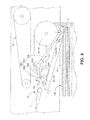
- FIG. 8 depicts an alternate embodiment of the present invention wherein a second cam is operative to pivot a bellcrank arm into contact with a face surface of a stacked mailpiece to separate the mailpiece from contact with a drive belt or roller of the ingestion assembly.
- FIG. 9 is a sectional view taken substantially along line 9 - 9 of FIG. 8 wherein the first and second cams are disposed on, and driven by, the shaft of the stepper motor.
- a divert assembly for a mailpiece sorter operative to sort mailpieces into one of a plurality of sortation bins.
- the divert assembly comprising a re-direct mechanism for selectively re-directing mailpieces travelling along a feed path into the sortation bin and causing each selected mailpiece to be re-directed at an angle relative to the stack of mailpieces to be accumulated in the sortation bin.
- the divert assembly also including a stacking assembly including a Leading Edge (LE) urge roller, a support blade, and a Trailing Edge (TE) alignment device.
- LE Leading Edge
- TE Trailing Edge
- the LE urge roller accepts and urges each of the selected mailpieces toward a sidewall of the sortation bin while the support blade holds each of the selected mailpieces between the urge roller and the support blade and in an on-edge parallel relationship relative thereto.
- the support blade is moveably mounted relative to the LE urge roller to allow the accumulation of additional mailpieces between the LE urge roller and the support blade.
- the TE alignment device includes a stepper motor rotationally driving a cam about a rotational axis. The cam defines a surface operative to urge the trailing edge portion of each selected mailpiece toward the support blade and into alignment with the stack.
- the present invention relates to a new and useful divert/stacking assembly for a sortation device.
- the divert/stacking assembly is described in the context of a multi-tiered sortation device, however, the invention is equally applicable to any sheet material sorter, e.g., linear, back-to-back, or tiered.
- the sheet material being sorted is commonly a finished mailpiece, however other sheet material is contemplated, such as the content material used in the fabrication of mailpieces, i.e., in a mailpiece inserter.
- mailpiece means any sheet material, sheet stock (postcard), envelope, magazine, folder, parcel, or package, which is substantially “flat” in two dimensions.
- a plurality of mailpieces are fed, scanned and sorted by a multi-tiered sorting system 10 .
- the principle modules of the multi-tiered sorting system 10 include: a sheet feeding apparatus 16 , a scanner 30 , a Level Distribution Unit (LDU) 40 , a multi-tiered stacker/sorter 50 , and a controller 60 . With respect to the latter, the overall operation of the multi-tiered stacker/sorter 10 is coordinated, monitored and controlled by the system controller 60 .
- LDU Level Distribution Unit
- each of the modules 16 , 30 , 40 and 50 may be individually controlled by one or more processors.
- the system controller 60 may also be viewed being controlled by one or more individual microprocessors.
- the sheet feeding apparatus 16 accepts a stack of mailpieces 14 between a plurality of singulating belts 20 at one end and a support blade 22 at the other end.
- the support blade 22 holds the mailpieces 14 in an on-edge, parallel relationship while a central conveyance belt 24 moves the support blade 22 , and consequently, the stack of mailpieces 14 , toward the singulation belts 24 in the direction of arrow FP.
- the mailpieces 14 are conveyed on-edge, in a direction orthogonal to the original feed path FP of the mailpiece stack. That is, each mailpiece 14 is fed in an on-edge lengthwise orientation across or passed a scanner 30 which identifies and reads specific information on the mailpiece 14 for sorting each mailpiece 14 into a sortation bin 80 (discussed hereinafter when describing the multi-tiered sorter 50 ).
- the scanner 30 reads the postal or ZIP code information to begin the RADIX sorting algorithm discussed in the Background of the Invention section of the present application.
- the scanner 30 may also be used to identify the type of mailpiece/parcel, e.g., as a postcard, magazine, which may be indicative of the weight or size of the mailpiece 14 being sorted.
- each mailpiece 14 is conveyed to the Level Distribution Unit (LDU) wherein, each mailpiece 14 is routed via a series of diverting flaps/vanes 42 , 44 , 46 , to the appropriate level or tier A, B, C or D of the multi-tiered sorter.
- the level A, B, C or D is determined by the controller 60 , based upon the information obtained by the scanner 30 . For example, if a mailpiece is destined for bin C3 (see FIG. 2 ), the LDU 40 routes a mailpiece 14 to level C by diverting the input feed path FP O , to the lower feed path FP2, of two feed paths FP1, FP2.
- the mailpiece 14 is then routed to the upper feed path FP5 of the two lower feed paths FP5, FP6 to arrive at level C.
- the LDU may handle and route mailpieces 14 in a variety ways to distribute mailpieces from an input feed path FP to an output feed path FP O , including the use of conventional nip rollers, spiral elastomeric rollers, opposing belts, etc.
- the orientation may be inverted from an on-edge to a horizontal orientation by a conventional twisted pair of opposing belts 48 shown at the input of the LDU 40 and/or visa versa to reverse the orientation, i.e., from a horizontal to an on-edge orientation (not shown) by the same type of inverting mechanism.
- each mailpiece 14 leaves the LDU 40 in an on-edge orientation and transported to a linear feed path LFP (see FIG. 1 ) on each level A, B, C, or D of the multi-tiered stacker/sorter 50 .
- Each linear feed path LFP is defined by a plurality of back-to-back belt drive mechanisms (discussed in greater detail below when discussing the components of the divert/stacking assembly of the present invention) which convey the mailpieces 14 to one of several sortation bins A1-A4, B1-B4, C1-C4, D1-D4, on each level of the stacker/sorter 50 .
- the linear feed path LFP may be defined by dedicated belt drive mechanisms
- the present invention employs elements of an inventive divert/stacking assembly 70 to convey the mailpieces along the linear feed path LFP.
- the divert/stacking assembly 70 of the present invention includes a re-direct mechanism 80 and a stacking assembly 90 to accumulate and stack mailpieces 14 into sortation bin A3. More specifically, the re-direct mechanism 80 is operative to selectively re-direct mailpieces 14 into sortation bin A3 by interrupting the linear motion thereof and diverting the selected mailpieces an angle ⁇ relative to the linear feed path LFP. This may be accomplished by understanding that the entire sorting system 10 is equipped with sensors.
- any mailpiece 14 e.g., photocells, encoders, to monitor the instantaneous location of any mailpiece 14 at any time along the various feed paths, including the location of the predetermined gaps between the trailing edge TE of one mailpiece 14 and the leading edge LE of a subsequent mailpiece.
- the re-direct mechanism 80 includes a conventional divert vane 82 and an actuator (not shown) operative to pivot the vane 82 about an axis 82 A into the feed path LPF of selected mailpieces 14 . While the re-direct mechanism 80 employs a pivotable vane 82 to divert select mailpieces 82 , any mechanism which interrupts the linear motion of the selected mailpieces 14 and diverts the same at an angle may be employed.
- the stacking assembly 90 includes a Leading Edge (LE) urge roller 84 , a support blade 86 and a Trailing Edge (TE) alignment device 88 .
- the LE urge roller 84 is operative to accept each of the selected mailpieces 14 and urge a leading edge portion LP thereof toward a sidewall 94 of the sortation bin A3.
- the urge roller 84 includes a pair of urge rollers 84 a , 84 b (see FIG. 4 ) which cooperate with a pair of drive belts 85 a , 85 b and a pair of upstream rollers 92 a , 92 b to drive selected mailpieces 14 into the bin A3 on one side thereof.
- the pair of drive belts 84 a , 84 b wrap around a pair of divert rollers 94 a , 94 b to drive other mailpieces 14 , e.g., non-selected mailpieces 14 , along the linear feed path LPF on the other side thereof. More specifically, the drive belts 85 a , 85 b cooperate with an opposing linear conveyance drive assembly 74 to capture and drive non-selected mailpieces 14 to another sortation bin A4 downstream of sortation bin A3.
- the support blade 86 is operative to hold the selected mailpieces 14 in an on-edge parallel orientation against the urge roller 84 . More specifically, the support blade 86 is disposed in a plane which is substantially parallel to the linear feed path LFP and orthogonal to the stack direction, i.e., in the direction of arrow SD, of the selected mailpieces 14 .
- the stacking assembly 90 includes a guide rod assembly 96 for mounting the support blade 86 relative to the urge roller 84 . More specifically, the guide rod assembly 96 includes a linear bearing 97 for moveably mounting the support blade 86 along a guide rod 98 toward or away from the urge roller 84 in the direction of arrow SS. In the described embodiment, the linear bearing assembly 97 and support blade 86 are spring-biased toward the urge roller 84 such that without a stack of selected mailpieces 14 , the support blade 86 rests against the respective urge roller 84 .
- the stacking assembly 90 includes a damping assembly 99 operative to damp the motion of the support blade 86 in the direction of arrow DD. That is, when the support blade moves outwardly, away from the urge roller 84 , the motion of the support blade 86 is damped. More specifically, low acceleration movement of the support blade 86 is dominated by the spring while a high acceleration motion of the support blade 86 is dominated by the damper 99 . The import of this arrangement will be discussed in greater detail hereinafter when discussing the operation of the divert/stacking assembly 70 of the present invention.
- the trailing edge (TE) alignment device 88 includes a first or dual-lobed beater cam 100 driven about an axis of rotation by a digital rotary positioning device or stepper motor 120 (see FIG. 6 ).
- the stepper motor 120 is a NEMA 17 frame motor.
- the inventors discovered through extensive research and inventive insight that integration of a low cost stepper motor 120 would require a precise cam profile 100 S capable of maintaining the necessary “holding torque” to drive the trailing edge TP of the selected mailpieces 14 into alignment. They determined that due to the torque limitations of conventional stepper motors a novel cam profile 100 S would be required to prevent motor stall.
- the cam profile 100 S is best described by reference to a table which identifies the locus of points N0-N31 about a common vertex 100V, each of the points N0-N31 being disposed on a radial line a distance X1-X31 from the vertex 100V, and at an angle ⁇ from a line of reference RL.
- the table defines cam profile in terms of the radial distance X as a function of the angle ⁇ from zero (0 ° ) degrees to one-hundred and forty degrees (140°).
- the radial distance X (Column IV) is measured from the vertex 100V of each point N0-N31 (Column I) on the surface of the cam. Furthermore, the radial distance X (Column IV) changes from one point to the next by the rise distance (Column III).
- the angle ⁇ (Column II) is measured from a line of reference RL.
- the cam profile may also be defined by the relationship given in equation 1.0 below.
- R ⁇ ( ⁇ ) R T / 2 ⁇ ( 1 - COS ⁇ ( ⁇ ⁇ ⁇ / ⁇ T ) ( 1.0 )
- ⁇ is an angle from a line of reference RL, wherein R( ⁇ ) is a rise height (in inches) at each angle ⁇ , wherein RT is a total rise height (in inches), and wherein ⁇ T is a total angle inscribed by the cam surface 100 S.
- the dual-lobed cam 100 is mounted to and rotates with a shaft 125 which is driven by a digital rotary positioning device or stepper motor.
- stepper motor is a NEMA 17 Frame bi-polar motor having two-hundred (200) steps, each step corresponding to about 1.8 degrees.
- FIG. 7 illustrates the control motion profile including a substantially linear rotational position curve 160 and a trapezoidal rotational velocity curve 170 . From the position curve 160 , it will be appreciated that the stepper motor 120 consumes about 0.0655 seconds to travel 0.5 revolutions or one-hundred eighty degrees (180°).
- mailpieces 14 are conveyed along the linear feed path LFP between the belts 84 a , 84 b of the ingestion assembly, i.e., the outboard side thereof, and the belts 75 a , 75 b of the linear conveyance assembly 74 .
- the re-direct assembly 80 receives a signal from the controller 60 to divert a selected mailpiece 14 into the sortation bin, i.e., sortation bin A3 in FIG. 3 .
- the selected mailpiece 14 is initially re-directed at an angle ⁇ while the leading edge alignment device 84 , i.e., the urge rollers 84 a , 84 b in combination with the drive belts 85 a , 85 b , urge the leading edge portion LP (shown in phantom lines in FIG. 3 ) of a selected mailpiece 14 toward a sidewall portion of the sortation bin A3.
- the controller 60 then issues a signal to the trailing edge alignment device 88 , i.e. the dual-lobed cam 100 and digital rotary positioning device 120 , to rotate approximately one-hundred and forty degrees (140°) to urge the trailing edge portion TP into parallel alignment with the support blade 86 or the previously stacked mailpieces 14 .
- FIGS. 8 and 9 another embodiment of the invention is depicted wherein an anti-abrasion assembly 200 is employed in combination with the ingestion assembly 90 to protect stacked mailpieces from damage due to abrasion. More specifically, the anti-abrasion assembly 200 allows the continuous operation of the ingestion assembly 90 , i.e., the urge rollers 84 a , 84 b and drive belts 85 a , 84 b , without incurring abrasion to a surface of the stacked mailpieces 14 S.
- the ingestion assembly 90 i.e., the urge rollers 84 a , 84 b and drive belts 85 a , 84 b
- the inventors recognized a synergistic use of the digital rotary positioning device 120 of the Trailing Edge alignment device 88 for control in combination with an anti-abrasion device 200 . More specifically, the inventors recognized that inasmuch as the positioning device 120 has the ability for precise positioning control, including reverse control, an opportunity arises to employ this motion to disengage the stack during certain operational modes. i.e., an idle mode when mailpieces are not being stacked or accumulated into a particular sortation bin.
- the anti-abrasion assembly 200 includes anti-abrasion linkage 202 responsive to rotation of the digital rotary positioning device 120 to forcibly displace a surface 210 of the stacked mailpieces 14 away from a moving surface of the ingestion assembly 84 .
- the anti-abrasion assembly 200 includes the anti-abrasion link 202 and a second cam 204 disposed about and rotating with the shaft 125 of the stepper motor 120 .
- the anti-abrasion linkage 202 is pivotally mounted about support axis 202 A which is disposed between the urge rollers 84 a , 84 b of the leading edge alignment assembly 84 and the drive rollers 92 a , 92 b of the trailing edge alignment device 88 .
- the linkage 202 includes an input arm 206 operative to contact a lobed cam surface 204 S of the second cam 204 and an output arm 208 a operative to contact the innermost mailpiece 14 i of the stack of mailpieces 14 S.
- the input arm 204 Upon rotating the shaft 125 of the stepper motor 120 , the input arm 204 follows the cam surface 204 S which causes the linkage 202 to rotate in the direction of arrow 212 . Furthermore, inasmuch as the linkage 202 is configured as a bellcrank or lever, rotation of the input arm 206 also effects rotation of the output arm 208 toward the innermost mailpiece 14 i of the stack 14 S.
- the first or dual-lobed cam 100 rotates in approximately one-hundred and eighty degree (180°) increments, and minimally one-hundred and forty degree (140°) degree increments, to urge the trailing edge portion of the selected mailpieces.
- the second cam 204 While in an idle condition, i.e., when mailpieces 14 are not being diverted or selected into the sortation bin, the second cam 204 imparts a rotary motion to the anti-abrasion linkage 202 , i.e., about the rotational axis 212 , such that the output arm 208 separates, or effects a gap between, the innermost mailpiece 14 i of the stack 14 S and the urge roller 84 a , 84 b and the drive belts 85 a , 85 b .
- the second cam 204 may be clutch mounted (not shown) to the drive shaft 125 .
- the clutch mount may be of an overrunning-type such that when the shaft 125 rotates in one direction, i.e. the direction for rotating and activating the dual-lobed cam 100 , the second cam 204 is disengaged. However, when rotated in the opposite direction, the over-running clutch mount engages the second cam 204 to impart motion to the anti-abrasion linkage 202 .
- divert/stacking assembly employs a low cost, controllable, and highly accurate positioning device to drive a dual lobed cam for aligning mailpieces in a sortation bin.
- the dual lobed cam includes an optimum surface contour or profile to minimize torque on the shaft without inducing a stall condition in the positioning device.
- the invention describes an embodiment wherein the positioning device is also used to prevent abrasion of mailpieces while sitting idle awaiting additional mailpieces to be stacked in the sortation bin.
Landscapes
- Engineering & Computer Science (AREA)
- Mechanical Engineering (AREA)
- Sorting Of Articles (AREA)
Abstract
Description
P (# of Bins)=# of Destinations (1.0)
| TABLE I | |||||
| Total | |||||
| Point No. | Angle (θ) | Rise (in) | Displacement (X − in) | ||
| 1 | 0.00 | 0.000 | 0.538 | ||
| 2 | 4.65 | 0.002 | 0.540 | ||
| 3 | 9.33 | 0.006 | 0.544 | ||
| 4 | 14.000 | 0.014 | 0.552 | ||
| 5 | 18.667 | 0.025 | 0.563 | ||
| 6 | 23.333 | 0.039 | 0.577 | ||
| 7 | 28.000 | 0.056 | 0.594 | ||
| 8 | 32.667 | 0.076 | 0.614 | ||
| 9 | 37.333 | 0.097 | 0.635 | ||
| 10 | 42.000 | 0.121 | 0.659 | ||
| 11 | 46.667 | 0.147 | 0.685 | ||
| 12 | 51.333 | 0.174 | 0.712 | ||
| 13 | 56.000 | 0.203 | 0.741 | ||
| 14 | 60.667 | 0.233 | 0.771 | ||
| 15 | 65.333 | 0.263 | 0.801 | ||
| 16 | 70.000 | 0.294 | 0.832 | ||
| 17 | 74.667 | 0.325 | 0.863 | ||
| 18 | 79.333 | 0.355 | 0.893 | ||
| 19 | 84.000 | 0.385 | 0.923 | ||
| 20 | 88.667 | 0.414 | 0.952 | ||
| 21 | 93.333 | 0.441 | 0.979 | ||
| 22 | 98.000 | 0.467 | 1.005 | ||
| 23 | 102.667 | 0.491 | 1.029 | ||
| 24 | 107.333 | 0.512 | 1.050 | ||
| 25 | 112.000 | 0.532 | 1.070 | ||
| 26 | 116.667 | 0.549 | 1.087 | ||
| 27 | 121.333 | 0.563 | 1.101 | ||
| 28 | 126.000 | 0.574 | 1.112 | ||
| 29 | 130.667 | 0.582 | 1.120 | ||
| 30 | 135.333 | 0.586 | 1.124 | ||
| 31 | 140.000 | 0.588 | 1.126 | ||
| TABLE | |||
| Max Speed | |||
| 9 revolutions/second | |||
| Cycle Time | 0.0655 second | ||
| Stoke | 0.5 revolutions | ||
| T1 = T3 | 0.010 seconds | ||
| T2 | 0.0456 seconds | ||
| Acceleration Distance | 0.04475 revolutions | ||
| Acceleration Rate | 905 revolutions/second2 | ||
| Constant Velocity Distance | 0.410 revolutions | ||
Claims (12)
Priority Applications (2)
| Application Number | Priority Date | Filing Date | Title |
|---|---|---|---|
| US13/659,766 US8748769B2 (en) | 2012-10-24 | 2012-10-24 | Stacking assembly for a mailpiece sorter |
| EP13188889.3A EP2724963A1 (en) | 2012-10-24 | 2013-10-16 | Stacking assembly for a mailpiece sorter |
Applications Claiming Priority (1)
| Application Number | Priority Date | Filing Date | Title |
|---|---|---|---|
| US13/659,766 US8748769B2 (en) | 2012-10-24 | 2012-10-24 | Stacking assembly for a mailpiece sorter |
Publications (2)
| Publication Number | Publication Date |
|---|---|
| US20140110312A1 US20140110312A1 (en) | 2014-04-24 |
| US8748769B2 true US8748769B2 (en) | 2014-06-10 |
Family
ID=49385130
Family Applications (1)
| Application Number | Title | Priority Date | Filing Date |
|---|---|---|---|
| US13/659,766 Active US8748769B2 (en) | 2012-10-24 | 2012-10-24 | Stacking assembly for a mailpiece sorter |
Country Status (2)
| Country | Link |
|---|---|
| US (1) | US8748769B2 (en) |
| EP (1) | EP2724963A1 (en) |
Cited By (2)
| Publication number | Priority date | Publication date | Assignee | Title |
|---|---|---|---|---|
| US20140110313A1 (en) * | 2012-10-24 | 2014-04-24 | Pitney Bowes, Inc. | Anti-abrasion assembly for mailpiece stacking assembly |
| US10730079B2 (en) | 2018-10-03 | 2020-08-04 | Dmt Solutions Global Corporation | Cam stacking assembly for a mixed sized mail-piece sorter |
Families Citing this family (4)
| Publication number | Priority date | Publication date | Assignee | Title |
|---|---|---|---|---|
| DE102015200618B4 (en) * | 2015-01-16 | 2026-02-26 | Körber Supply Chain Logistics Gmbh | Sorting device and method for sorting unit loads |
| WO2019216913A1 (en) * | 2018-05-11 | 2019-11-14 | Hewlett-Packard Development Company, L.P. | Knockdown for compiling recording media in finisher |
| EP3590876B1 (en) | 2018-07-03 | 2021-03-31 | Canon Production Printing Holding B.V. | Paper path structure, stacker, printer and method for operating a paper path structure |
| US11414294B2 (en) | 2019-12-31 | 2022-08-16 | Dmt Solutions Global Corporation | System and method for folding paper carriers with attached cards |
Citations (4)
| Publication number | Priority date | Publication date | Assignee | Title |
|---|---|---|---|---|
| US5109987A (en) * | 1989-12-04 | 1992-05-05 | National Presort, Inc. | Multi-level sort machine |
| US20050056991A1 (en) * | 1999-03-31 | 2005-03-17 | Sullivan John Anthony | Sheet material processing |
| US20050056575A1 (en) * | 2003-08-01 | 2005-03-17 | Lg N-Sys Inc. | Media thickness detector |
| US20070252323A1 (en) * | 2006-04-26 | 2007-11-01 | Xerox Corporation | High speed sheet path gating system |
Family Cites Families (7)
| Publication number | Priority date | Publication date | Assignee | Title |
|---|---|---|---|---|
| US3814415A (en) * | 1972-07-27 | 1974-06-04 | Burroughs Corp | Device for aiding the stacking of documents |
| FR2538797B1 (en) * | 1982-12-30 | 1986-02-14 | Hotchkiss Brandt Sogeme | DEVICE FOR STACKING FLAT OBJECTS |
| US4903956A (en) | 1988-10-31 | 1990-02-27 | Stephens David J | Sheet stacking apparatus having positive control system for trailing sheet ends |
| DE10118758C1 (en) * | 2001-04-17 | 2002-05-23 | Siemens Production & Logistics | Stacking device, for flat flexible objects, has at least two diverting elements at side of track of object |
| US6877739B2 (en) * | 2002-12-16 | 2005-04-12 | Pitney Bowes Inc. | Vertical stacker input method and apparatus |
| US7967291B1 (en) * | 2005-07-26 | 2011-06-28 | National Presort, Inc. | Detent to prevent jamming of a document sorting machine |
| FR2961417A1 (en) * | 2010-06-17 | 2011-12-23 | Solystic | DEVICE FOR STACKING FLAT OBJECTS ON THE EDGE, ITS STEERING METHOD, AND POSTAL SORTING MACHINE EQUIPPED WITH AT LEAST ONE SUCH DEVICE |
-
2012
- 2012-10-24 US US13/659,766 patent/US8748769B2/en active Active
-
2013
- 2013-10-16 EP EP13188889.3A patent/EP2724963A1/en not_active Withdrawn
Patent Citations (4)
| Publication number | Priority date | Publication date | Assignee | Title |
|---|---|---|---|---|
| US5109987A (en) * | 1989-12-04 | 1992-05-05 | National Presort, Inc. | Multi-level sort machine |
| US20050056991A1 (en) * | 1999-03-31 | 2005-03-17 | Sullivan John Anthony | Sheet material processing |
| US20050056575A1 (en) * | 2003-08-01 | 2005-03-17 | Lg N-Sys Inc. | Media thickness detector |
| US20070252323A1 (en) * | 2006-04-26 | 2007-11-01 | Xerox Corporation | High speed sheet path gating system |
Cited By (3)
| Publication number | Priority date | Publication date | Assignee | Title |
|---|---|---|---|---|
| US20140110313A1 (en) * | 2012-10-24 | 2014-04-24 | Pitney Bowes, Inc. | Anti-abrasion assembly for mailpiece stacking assembly |
| US8987626B2 (en) * | 2012-10-24 | 2015-03-24 | Pitney Bowes Inc. | Anti-abrasion assembly for mailpiece stacking assembly |
| US10730079B2 (en) | 2018-10-03 | 2020-08-04 | Dmt Solutions Global Corporation | Cam stacking assembly for a mixed sized mail-piece sorter |
Also Published As
| Publication number | Publication date |
|---|---|
| US20140110312A1 (en) | 2014-04-24 |
| EP2724963A1 (en) | 2014-04-30 |
Similar Documents
| Publication | Publication Date | Title |
|---|---|---|
| US8987626B2 (en) | Anti-abrasion assembly for mailpiece stacking assembly | |
| US8748769B2 (en) | Stacking assembly for a mailpiece sorter | |
| US5485989A (en) | Diverter and on-edge stacker | |
| US20180264521A1 (en) | Installation for sorting articles with a sorting conveyor having pivotally mounted flaps | |
| CA2135844C (en) | On-line sorting for an inserter system | |
| US5971161A (en) | Mailpiece sorting device | |
| US8256760B2 (en) | System for controlling a drive belt in a mailpiece feeder | |
| EP1676646A1 (en) | System for grouping mailpieces in a sorter | |
| US7841594B2 (en) | Apparatus for altering the orientation and/or direction of sheet material in mailpiece fabrication systems | |
| US9114432B2 (en) | Device for sorting and conveying documents | |
| US8757352B1 (en) | Downstream diverter | |
| US8123222B2 (en) | Compliant conveyance system for mailpiece transport along an arcuate feed path | |
| US20200316651A1 (en) | Cam stacking assembly for a mixed sized mail-piece sorter | |
| US7770889B2 (en) | Sheet material sorter and pneumatic conveyance/diverting system therefor | |
| US8517660B2 (en) | Traction control for singulating mailpieces in a mailpiece feeder | |
| EP2238060B1 (en) | Transport for singulating items | |
| US20090107892A1 (en) | Sheet material transposition for sorting apparatus | |
| US20090160118A1 (en) | Item transport with singulation detection | |
| EP2428475B1 (en) | System for controlling a singulating belt in a mailpiece feeder | |
| US8596635B2 (en) | System for controlling mailpiece conveyance in a mailpiece feeder | |
| US8038149B2 (en) | Alignment/registration and conveyance apparatus |
Legal Events
| Date | Code | Title | Description |
|---|---|---|---|
| AS | Assignment |
Owner name: PITNEY BOWES INC., CONNECTICUT Free format text: ASSIGNMENT OF ASSIGNORS INTEREST;ASSIGNORS:ALLEN, ROBERT J.;LYGA, THOMAS M.;SWINFORD, BRAD A.;AND OTHERS;SIGNING DATES FROM 20121106 TO 20121112;REEL/FRAME:029371/0019 |
|
| STCF | Information on status: patent grant |
Free format text: PATENTED CASE |
|
| MAFP | Maintenance fee payment |
Free format text: PAYMENT OF MAINTENANCE FEE, 4TH YEAR, LARGE ENTITY (ORIGINAL EVENT CODE: M1551) Year of fee payment: 4 |
|
| AS | Assignment |
Owner name: DEUTSCHE BANK AG NEW YORK BRANCH, NEW YORK Free format text: SECURITY AGREEMENT;ASSIGNOR:DMT SOLUTIONS GLOBAL CORPORATION;REEL/FRAME:046467/0901 Effective date: 20180702 |
|
| AS | Assignment |
Owner name: DEUTSCHE BANK AG NEW YORK BRANCH, NEW YORK Free format text: TERM LOAN SECURITY AGREEMENT;ASSIGNOR:DMT SOLUTIONS GLOBAL CORPORATION;REEL/FRAME:046473/0586 Effective date: 20180702 |
|
| AS | Assignment |
Owner name: DMT SOLUTIONS GLOBAL CORPORATION, CONNECTICUT Free format text: ASSIGNMENT OF ASSIGNORS INTEREST;ASSIGNOR:PITNEY BOWES INC.;REEL/FRAME:046597/0120 Effective date: 20180627 |
|
| MAFP | Maintenance fee payment |
Free format text: PAYMENT OF MAINTENANCE FEE, 8TH YEAR, LARGE ENTITY (ORIGINAL EVENT CODE: M1552); ENTITY STATUS OF PATENT OWNER: LARGE ENTITY Year of fee payment: 8 |
|
| AS | Assignment |
Owner name: BANK OF AMERICA, N.A., AS COLLATERAL AGENT, NEW YORK Free format text: SECURITY AGREEMENT;ASSIGNORS:BCC SOFTWARE, LLC;DMT SOLUTIONS GLOBAL CORPORATION;REEL/FRAME:064784/0295 Effective date: 20230830 Owner name: DMT SOLUTIONS GLOBAL CORPORATION, CONNECTICUT Free format text: RELEASE BY SECURED PARTY;ASSIGNOR:DEUTSCHE BANK AG NEW YORK BRANCH;REEL/FRAME:064785/0374 Effective date: 20230830 Owner name: DMT SOLUTIONS GLOBAL CORPORATION, CONNECTICUT Free format text: RELEASE BY SECURED PARTY;ASSIGNOR:DEUTSCHE BANK AG NEW YORK BRANCH;REEL/FRAME:064785/0325 Effective date: 20230830 |
|
| AS | Assignment |
Owner name: SILVER POINT FINANCE, LLC, ILLINOIS Free format text: SECURITY INTEREST;ASSIGNORS:BCC SOFTWARE, LLC;DMT SOLUTIONS GLOBAL CORPORATION;REEL/FRAME:064819/0445 Effective date: 20230830 |
|
| MAFP | Maintenance fee payment |
Free format text: PAYMENT OF MAINTENANCE FEE, 12TH YEAR, LARGE ENTITY (ORIGINAL EVENT CODE: M1553); ENTITY STATUS OF PATENT OWNER: LARGE ENTITY Year of fee payment: 12 |