EP1424290B1 - Packaging bag and method for manufacturing same - Google Patents
Packaging bag and method for manufacturing same Download PDFInfo
- Publication number
- EP1424290B1 EP1424290B1 EP20030026606 EP03026606A EP1424290B1 EP 1424290 B1 EP1424290 B1 EP 1424290B1 EP 20030026606 EP20030026606 EP 20030026606 EP 03026606 A EP03026606 A EP 03026606A EP 1424290 B1 EP1424290 B1 EP 1424290B1
- Authority
- EP
- European Patent Office
- Prior art keywords
- pair
- bag body
- main bag
- framework member
- strips
- Prior art date
- Legal status (The legal status is an assumption and is not a legal conclusion. Google has not performed a legal analysis and makes no representation as to the accuracy of the status listed.)
- Expired - Lifetime
Links
Images








Classifications
-
- B—PERFORMING OPERATIONS; TRANSPORTING
- B65—CONVEYING; PACKING; STORING; HANDLING THIN OR FILAMENTARY MATERIAL
- B65D—CONTAINERS FOR STORAGE OR TRANSPORT OF ARTICLES OR MATERIALS, e.g. BAGS, BARRELS, BOTTLES, BOXES, CANS, CARTONS, CRATES, DRUMS, JARS, TANKS, HOPPERS, FORWARDING CONTAINERS; ACCESSORIES, CLOSURES, OR FITTINGS THEREFOR; PACKAGING ELEMENTS; PACKAGES
- B65D33/00—Details of, or accessories for, sacks or bags
- B65D33/02—Local reinforcements or stiffening inserts, e.g. wires, strings, strips or frames
-
- B—PERFORMING OPERATIONS; TRANSPORTING
- B31—MAKING ARTICLES OF PAPER, CARDBOARD OR MATERIAL WORKED IN A MANNER ANALOGOUS TO PAPER; WORKING PAPER, CARDBOARD OR MATERIAL WORKED IN A MANNER ANALOGOUS TO PAPER
- B31B—MAKING CONTAINERS OF PAPER, CARDBOARD OR MATERIAL WORKED IN A MANNER ANALOGOUS TO PAPER
- B31B70/00—Making flexible containers, e.g. envelopes or bags
- B31B70/008—Stiffening or reinforcing
-
- B—PERFORMING OPERATIONS; TRANSPORTING
- B65—CONVEYING; PACKING; STORING; HANDLING THIN OR FILAMENTARY MATERIAL
- B65B—MACHINES, APPARATUS OR DEVICES FOR, OR METHODS OF, PACKAGING ARTICLES OR MATERIALS; UNPACKING
- B65B29/00—Packaging of materials presenting special problems
- B65B29/02—Packaging of substances, e.g. tea, which are intended to be infused in the package
- B65B29/028—Packaging of substances, e.g. tea, which are intended to be infused in the package packaging infusion material into filter bags
-
- B—PERFORMING OPERATIONS; TRANSPORTING
- B31—MAKING ARTICLES OF PAPER, CARDBOARD OR MATERIAL WORKED IN A MANNER ANALOGOUS TO PAPER; WORKING PAPER, CARDBOARD OR MATERIAL WORKED IN A MANNER ANALOGOUS TO PAPER
- B31B—MAKING CONTAINERS OF PAPER, CARDBOARD OR MATERIAL WORKED IN A MANNER ANALOGOUS TO PAPER
- B31B2150/00—Flexible containers made from sheets or blanks, e.g. from flattened tubes
-
- B—PERFORMING OPERATIONS; TRANSPORTING
- B31—MAKING ARTICLES OF PAPER, CARDBOARD OR MATERIAL WORKED IN A MANNER ANALOGOUS TO PAPER; WORKING PAPER, CARDBOARD OR MATERIAL WORKED IN A MANNER ANALOGOUS TO PAPER
- B31B—MAKING CONTAINERS OF PAPER, CARDBOARD OR MATERIAL WORKED IN A MANNER ANALOGOUS TO PAPER
- B31B2155/00—Flexible containers made from webs
-
- B—PERFORMING OPERATIONS; TRANSPORTING
- B31—MAKING ARTICLES OF PAPER, CARDBOARD OR MATERIAL WORKED IN A MANNER ANALOGOUS TO PAPER; WORKING PAPER, CARDBOARD OR MATERIAL WORKED IN A MANNER ANALOGOUS TO PAPER
- B31B—MAKING CONTAINERS OF PAPER, CARDBOARD OR MATERIAL WORKED IN A MANNER ANALOGOUS TO PAPER
- B31B2155/00—Flexible containers made from webs
- B31B2155/002—Flexible containers made from webs by joining superimposed webs, e.g. with separate bottom webs
-
- B—PERFORMING OPERATIONS; TRANSPORTING
- B31—MAKING ARTICLES OF PAPER, CARDBOARD OR MATERIAL WORKED IN A MANNER ANALOGOUS TO PAPER; WORKING PAPER, CARDBOARD OR MATERIAL WORKED IN A MANNER ANALOGOUS TO PAPER
- B31B—MAKING CONTAINERS OF PAPER, CARDBOARD OR MATERIAL WORKED IN A MANNER ANALOGOUS TO PAPER
- B31B2160/00—Shape of flexible containers
- B31B2160/10—Shape of flexible containers rectangular and flat, i.e. without structural provision for thickness of contents
-
- B—PERFORMING OPERATIONS; TRANSPORTING
- B31—MAKING ARTICLES OF PAPER, CARDBOARD OR MATERIAL WORKED IN A MANNER ANALOGOUS TO PAPER; WORKING PAPER, CARDBOARD OR MATERIAL WORKED IN A MANNER ANALOGOUS TO PAPER
- B31B—MAKING CONTAINERS OF PAPER, CARDBOARD OR MATERIAL WORKED IN A MANNER ANALOGOUS TO PAPER
- B31B2170/00—Construction of flexible containers
- B31B2170/20—Construction of flexible containers having multi-layered walls, e.g. laminated or lined
-
- B—PERFORMING OPERATIONS; TRANSPORTING
- B31—MAKING ARTICLES OF PAPER, CARDBOARD OR MATERIAL WORKED IN A MANNER ANALOGOUS TO PAPER; WORKING PAPER, CARDBOARD OR MATERIAL WORKED IN A MANNER ANALOGOUS TO PAPER
- B31B—MAKING CONTAINERS OF PAPER, CARDBOARD OR MATERIAL WORKED IN A MANNER ANALOGOUS TO PAPER
- B31B70/00—Making flexible containers, e.g. envelopes or bags
- B31B70/74—Auxiliary operations
- B31B70/81—Forming or attaching accessories, e.g. opening devices, closures or tear strings
- B31B70/812—Applying patches, strips or strings on sheets or webs
- B31B70/8123—Applying strips
-
- Y—GENERAL TAGGING OF NEW TECHNOLOGICAL DEVELOPMENTS; GENERAL TAGGING OF CROSS-SECTIONAL TECHNOLOGIES SPANNING OVER SEVERAL SECTIONS OF THE IPC; TECHNICAL SUBJECTS COVERED BY FORMER USPC CROSS-REFERENCE ART COLLECTIONS [XRACs] AND DIGESTS
- Y02—TECHNOLOGIES OR APPLICATIONS FOR MITIGATION OR ADAPTATION AGAINST CLIMATE CHANGE
- Y02W—CLIMATE CHANGE MITIGATION TECHNOLOGIES RELATED TO WASTEWATER TREATMENT OR WASTE MANAGEMENT
- Y02W30/00—Technologies for solid waste management
- Y02W30/50—Reuse, recycling or recovery technologies
- Y02W30/80—Packaging reuse or recycling, e.g. of multilayer packaging
Definitions
- US 2,330,015 A refers to a container.
- the container is formed from multi-ply webbed shaped and marginally joined to comprise nested tubes which are substantially free of attachment to each other except at transfer seals formed by tools or equivalent, defining the ends of the containers.
- Such a packaging bag is composed of a main bag body made of plastic film material and a sleeve disposed therein. The sleeve is foldable/unfoldable and is inserted into the main bag body from an opening thereof.
- the sleeve having the suitable size is not easy to insert the sleeve having the suitable size into the main bag body from the opening thereof. More specifically, when the length of the opening of the main bag body, which is kept in the collapsed state, is identical to the width of the sleeve, which is also kept in the collapsed state, the total thickness of the collapsed sleeve makes it difficult to insert the sleeve into the main bag body, because of no existence of gusset. In case where the main bag body is provided in its opening with a linear fastener, the liner fastener makes the insertion operation of the sleeve more difficult. Such difficulty in insertion operation of the sleeve deteriorates a manufacturing efficiency of the packaging bag, thus leading to an increased manufacturing cost thereof.
- An object of the present invention which was made to solve the above-described problems, is to provide a packaging bag, which permits to facilitate manufacture thereof, thus reducing the manufacturing cost, and provide an excellent external appearance in an expanded state.
- each of the upper and lower side edges of the reinforcing section is substantially identical to the width of the main bag body 2 so that the right and left hand side edges of the reinforcing section are embedded in the side heat-sealed portions 4, 4.
- Each of the upper and lower side edges of each of the reinforcing sections is thermally bonded to the inner surface of each of the panel members 3, 3 at the other regions than the side heat-sealed portions 4, 4.
- the male member 5a of the linear fastener 5 is composed of three sections, i.e., a set of a central main section and opposite side sections, which are placed in line so as to be apart from each other, as shown in FIG. 7 . Gaps between the central main section and the opposite side sections are placed so as to correspond to the above-mentioned bending facilitation portions.
- the female member 5b of the linear fastener 5 is also composed of three sections in the similar manner as the male member 5a. The gaps of each of the male member 5a and the female member 5b enable the main bag body 2 to be easily folded in accordance with the shift of the framework member 10 between the collapsed state and the expanded state.
- the main bag body 2 and the framework member 10 are designed so that the height of the framework member 10 is substantially identical to the height of the packaging bag 1, which is shifted to an expanded state and subjected to a bending finishing step to provide a finished product in the form of a rectangular parallelepiped.
- the framework member 10 is bent at right angles at the bending facilitation portions 11, 11, thus forming the four side corner edges of the rectangular parallelepiped.
- the packaging bag 1 having the above-described structure is shifted from the generally flat collapsed state as shown in FIG. 1 to the expanded finished state as shown in FIG. 6 through the intermediate states as shown in FIGS. 2 to 5 .
- the opposite sides of the packaging bag 1, which is kept in the generally flat collapsed state, are pushed inwardly in directions as shown by arrows in FIG. 2 , with the result that the pair of opposite reinforcing sections of the framework member 10 are folded at right angles along the bending facilitation portions 11, 11, thus shifting the framework member 10 together with the main bag body 2 from the generally flat collapsed state to the expanded state in the form of sleeve.
- Such a pushing operation provides opposite front and rear panel portions 8a, 8b, and opposite side panel portions 6, 6.
- the above-mentioned pushing operation also provides an upper portion 3a, which upwardly projects from the upper edge 12 of the framework member 10, and a lower portion 3b, which downwardly projects from the lower edge 13 of the framework member 10. In such a pushing operation, the side heat-sealed portions 4, 4 are bent rearward.
- the upper portion 3a which upwardly projects from the upper edge of the framework member 10, is also folded along the upper edge 12 of the framework member 10 into a flat state so as to provide a pair of trapezoidal portions 9a, 9a projecting outwardly and generally horizontally as shown in FIG. 5 .
- the opening of the packaging bag 1, which is closed by the linear fastener 5, is brought close to the rear panel portion 8b.
- the above-mentioned pair of trapezoidal portions 9a, 9a is bent downwardly along the upper edge of the framework member 10 and thermally bonded to the opposite side panel portions 6, 6, respectively, thus providing a finished product, as shown in FIG. 6 .
- the folding process of the upper portion 3a of the packaging bag 1 to form the top panel portion 9 is completed in this manner. Any other suitable bonding may be applicable to the bonding of the trapezoidal portions 9a, 9a, and these portions 9a, 9a may be bonded to the opposite side panel portions 6, 6 by a suitable adhesive agent. Of course, the above-mentioned folding process is carried out after the packaging bag 1 is filled with contents.
- the packaging bag 1 which is shifted from the generally flat collapsed state to the expanded state, this providing an external appearance of the box, has the opposite front and rear panel portions 8a, 8b, which face in parallel with each other, the side panel portions 6, 6, which also face in parallel with each other on the opposite sides of the front and rear panel portions 8a, 8b, the bottom panel portion 7 that has been formed by folding the bottom portion 3b of the packaging bag 1 in the flat state, and the top panel portion 9 that has been formed by folding the upper portion 3a of the packaging bag 1 in the flat state.
- the height of each of the front and rear panel portions 8a, 8b and the side panel portions 6, 6 is substantially identical to the height of the framework member 10, which is provided in the packaging bag 1.
- the lower edge 13 of the framework member 10 forms the corners 1a, 1a, 1a, 1a between the front, rear and side panel portions 8a, 8b, 6, 6 and the bottom panel portion 7, on the one hand
- the upper edge 12 of the framework member 10 forms the comers 1c, 1c, 1c, 1c between the front, rear and side panel portions 8a, 8b, 6, 6 and the top panel portion 9, on the one hand.
- the bent portions of the framework member 10, which are provided by bending the framework member 10 along the bending facilitation portions 11, form the corners 1b, 1b, 1b, 1b between the front and rear panel portions 8a, 8b and the side panel portions 6, 6.
- the packaging bag 1 can be shifted from the generally flat collapsed state to the expanded state and then subjected to the folding processes to convert into a box shape, which corresponds to the framework member 10 kept in the expanded state. Accordingly, it is possible to receive products such as teabags having the predetermined shape in the packaging bag 1 kept in the expanded state, without collapsing their shapes.
- each of the upper and lower side edges of each of the reinforcing sections of the framework member 10 is thermally bonded to the inner surface of each of the panel members, 3, 3 at the other regions than the side heat-sealed portions 4, 4.
- each of the reinforcing sections of the framework member 10 is may not necessarily bonded to the inner surface of each of the panel members 3, 3 at the other regions than the side heat-sealed portions 4, 4, in case where a proper contact state of the reinforcing sections with the inner surface of the panel members 3, 3 can be ensured, or an existence of a possible gap between the reinforcing sections and the panel members 3, 3 cause no problem in a filling operation of the packaging bag 1 with contents.
- the above-described packaging bag 1 of the embodiment of the present invention is provided with the linear fastener 5.
- the single strip 20 for the main bag body 2 and the pair of strips 30, 30 for the framework member 10 are used to manufacture the plurality of packaging bags 1.
- the method for manufacturing the packaging bag 1 includes the essential steps of:
- the step (1-a) is carried out to unroll the single strip 20 of plastic film material for the main bag body 2 to continuously feed it in the longitudinal direction.
- the single strip 20 has the opposite half portions between which the longitudinal central line of the single strip 20 exists.
- the layer structure of the single strip 20 of plastic film material for the main bag body 2 is the same as that of the main bag body 2 of the packaging bag 1 of the present invention as described above and description of the layer structure is therefore omitted.
- the step (1-h) is carried out to continuously provide a plurality of sets of male members 5a and a plurality of corresponding sets of female members 5b on the longitudinal opposite side edge portions of the upper surface of the single strip 20 for the main bag body 2, so as to form these members 5a, 5b integrally with the single strip 20 through an insert injection.
- a gap 15 exists between the adjacent sets of male members 5a and another gap 15 also exists between the adjacent sets of female members 5b corresponding to the above-mentioned gap 15.
- the corresponding gaps 15, 15 are placed on the same two-dot chain straight line as shown in FIG. 7 , which is perpendicular to the feeding direction of the single strip 20 for the main bag body 2.
- Each set of male members 5a is composed of a central main section and opposite side sections, which are placed in line so as to be apart from each other, as shown in FIG. 7 . Gaps 16•••16 between the central main section and the opposite side sections are placed so as to correspond to the bending facilitation portions 11•••11 as described later.
- Each set of female members 5b is also composed of three sections in the similar manner as the set of male members 5a. The set of male members 5a can be engaged with or removed from the set of female members 5b.
- the step (1-b) is carried out to unroll the pair of strips 30, 30 for the framework member 10 from a pair of rolls, which is disposed on the left-hand side of FIG. 8 , but not shown therein, to continuously feed them in their longitudinal directions to place them on the surface of the single strip 20 for the main bag body 2 in the predetermined positions of the respective half portions.
- the strips 30, 30 for the framework member 10 are unrolled at the different positions from each other and fed together in a prescribed zone, thus traveling in parallel with each other in their longitudinal directions.
- the step (1-g) is carried out to form the bending facilitation portions 11•••11 on the opposite inner surfaces of the pair of strips 30, 30 for the framework member 10 so as to extend in the perpendicular direction to the feeding direction of the pair of strips 30, 30 for the framework member 10.
- FIG. 9 shows a typical device for carrying out the above-mentioned step (1-g) to form the bending facilitation portions 11•••11 on each of the pair of strips 30, 30 for the framework member 10.
- the device is composed of a roller 40 provided with a projection 41 formed on the periphery thereof.
- the projection 41 extends over the roller 40 in its longitudinal direction.
- the central axis of the roller 40 is perpendicular to the feeding direction of the strip 30 for the framework member 10.
- a base plate (not shown) is disposed so as to face the roller 40 and extend along it in its longitudinal direction.
- the distance between the base plate and the outer peripheral surface of the roller 40 is substantially identical or smaller than the thickness of the strip 30 for the framework member 10.
- the above-mentioned base plate may be substituted by another roller having no projection.
- the strip 30 passes through between the base plate and the roller 40 to dig the projection 41 into the strip 30, thus forming a groove serving as the bending facilitation portion 11, which extends in the perpendicular direction to the feeding direction of the strip 30.
- a set of rollers i.e., the above-mentioned roller 40 and the other roller having the same structure, which are disposed so as to be away from each other by a predetermined distance, are utilized to form the above-described plurality of pairs of bending facilitation portions 11•••11 on one of the pair of strips 30, 30 for the framework member 10.
- the other set of rollers having the same structure are utilized to form the plurality of pairs of bending facilitation portions 11•••11 on the other of the pair of strips 30, 30 for the framework member 10. According to these sets of rollers, it is possible to continuously form the plurality of pairs of bending facilitation portions 11•••11 on the pair of strips 30, 30 for the framework member 10, without halting the feeding of the strips 30, 30.
- the pair of strips 30, 30 for the framework member 10, on which the bending facilitation portions 11•••11 have been formed by carrying out the step (1-g), is continuously fed, during the step (1-b), to place them on the inner surface of the single strip 20 for the main bag body 2 in the respective opposite half portions thereof.
- the step (1-f) is carried out to cut each of the heat-sealed portions 4•••4 in two in the perpendicular direction to the longitudinal direction of the folded composite strip, thereby continuously manufacturing the plurality of packaging bags 1.
- the opposite side edges of the reinforcing section, which are in parallel with the bending facilitation portions 11, 11 are embedded in the heat sealed portions 4, 4.
- each of the bending facilitation portions 11•••11 provided by the step (1-g) is formed into a groove.
- the bending facilitation portion 11 may have any other structure that enables the reinforcing section, which is obtained by cutting the strip 30, to be easily bent along the bending facilitation portion 11.
- the bending facilitation portion 11 may for example be provided in the different form for example of perforations.
- the insert injection is applied to carry out the step (1-h).
- the male members 5a and the female members 5b which have been previously formed through extrusion, may however be bonded to the single strip 20 for the main bag body 2.
- the overlapped portion 61a is then bent toward the rear panel portion 52 to provide a pair of trapezoidal portions 62a, 62a projecting outwardly.
- the pair of trapezoidal portions 62a, 62a is bent downwardly along the upper edge of the framework member 70 and thermally bonded to the opposite side panel portions 54, 54, respectively, thus providing a finished product, as shown in FIG. 13 .
- the folding process of the upper portion of the packaging bag 50 to form the top panel portion 62 is completed in this manner. Any other suitable bonding may be applicable to the bonding of the trapezoidal portions 62a, 62a, and these portions 62a, 62a may be bonded to the opposite side panel portions 54, 54 by a suitable adhesive agent.
- the above-mentioned folding process is carried out after the packaging bag 50 is filled with contents.
- FIG. 14 is a perspective view of the packaging bag 50, which is folded and then subjected to the additional folding process to provide the finished product, illustrating the bottom of the packaging bag 50.
- the packaging bag 50 When the packaging bag 50 is shifted from a generally flat collapsed state to the expanded state, the lower portion of the packaging bag 50 downwardly projects from the lower edge 72 of the framework member 70.
- the above-mentioned lower portion which has a bottom heat-sealed portion 57 formed on the lowermost edge thereof so as to extend in the width direction of the packaging bag 50, is folded along the lower edge 72 of the framework member 70 into a flat state so as to provide a pair of triangular portions 63a, 63a extending outwardly.
- the method for manufacturing the packaging bag 50 includes the essential steps of:
- the step (2-b) is carried out to unroll the pair of strips 90, 90 for the framework member 70 from the rolled strips 91, 91 to place them between the pair of strips 80, 80 for the main bag body 60 so that the pair of strips 90, 90 for the framework member 70 is located on respective inner surfaces of the pair of strips 80, 80 for the main bag body 60 in predetermined positions thereof.
- each of the strips 90, 90 for the main bag body 60 is made so as to keep a distance "L4" between the lower edge of the strips 80, 80 for the main bag body 60 and the lower edge of each of the strips 90, 90 and a distance "L3" between the upper edge of the each of the strips 90. 90 and the upper edge of the strips 80, 80 for the main bag body 60.
- the lower portion of the strips 80, 80 for the main bag body 60 which corresponds to the distance "L4", is used to form the bottom panel portions 55 of the packaging bags 50, as shown in FIG. 14 .
- the upper portion of the strips 80, 80 for the main bag body 60 which corresponds to the distance "L3" is used to form the top panel portions 53 of the packaging bags 50, as shown in FIG. 13 .
- the step (2-i) is carried out to form the bending facilitation portions 73•••73 on the opposite inner surfaces of the pair of strips 90, 90 for the framework member 70 so as to extend in the perpendicular direction to the feeding direction of the pair of strips 90, 90 for the framework member 70.
- the step (2-i) is identical to the step (1-g) described above of the first embodiment of the method of the present invention and the detailed description of the step (2-i) is therefore omitted.
- the steps (2-a) to (2-j) are carried out on the manufacturing line.
- the steps (2-a) to (2-j) may however be carried out independently each other on the different manufacturing lines.
- the step (4-c) is carried out to thermally bond the pair of pieces 160, 160 for the framework member to the pair of pieces 150, 150 for the main bag body, respectively.
- the pieces 160, 160 are thermally bonded at their periphery as hatched in FIG. 21 to the respective pieces 150, 150 for he main bag body.
Landscapes
- Engineering & Computer Science (AREA)
- Mechanical Engineering (AREA)
- Making Paper Articles (AREA)
- Bag Frames (AREA)
- Packages (AREA)
Description
- The present invention relates to a packaging bag according to the preamble of
claim 1. - Such a packaging bag is already known from
US 3,896,991 A . The packaging bag comprises a main bag body having an opening and a plurality of heat sealed portions and a framework member wherein the framework member is foldable/unfoldable together with the main bag body and the framework member has openings on the upper and lower side thereof. -
US 6,334,710 B1 describes a packaging bag comprising a main bag body which has an opening and a plurality of heat sealed portions, a framework member disposed in the main bag body and a linear fastener provided on the opening of the main bag body. -
US 4,082,216 A refers to a collapsible carton and plastic bag container comprising a main bag body made of a plastic film material through a main body formation process. A framework body member is disposed in the main bag body. The framework member is joined to the main bag body prior to completion of the main bag body formation process. Moreover, the framework member is foldable and unfoldable together with the main bag body, to enable the framework member and the main bag body to be shifted between a generally flat collapsed state and an expanded state. -
US 2,330,015 A refers to a container. The container is formed from multi-ply webbed shaped and marginally joined to comprise nested tubes which are substantially free of attachment to each other except at transfer seals formed by tools or equivalent, defining the ends of the containers. - There have conventionally been various kinds of packaging bags made of plastic film material. There has recently been a strong demand to cause such a packaging bag to receive products such as teabags having predetermined shapes, without collapsing their shapes. The applicant has pursued the development of a packaging bag in response to the above-mentioned demand. Such a packaging bag is composed of a main bag body made of plastic film material and a sleeve disposed therein. The sleeve is foldable/unfoldable and is inserted into the main bag body from an opening thereof. Accordingly, the sleeve received in the main bag body is foldable/unfoldable together with the main bag body, to enable the sleeve and the main bag body to be shifted between a generally flat collapsed state and an expanded state.
Japanese Laid-Open Patent Application No. 2001-322187 - In the above-mentioned packaging bag, it is essential to place the sleeve having a suitable size to the main bag body in proper position in the main bag body, in order to provide an excellent external appearance of the packaging bag in the expanded state.
- However, it is not easy to insert the sleeve having the suitable size into the main bag body from the opening thereof. More specifically, when the length of the opening of the main bag body, which is kept in the collapsed state, is identical to the width of the sleeve, which is also kept in the collapsed state, the total thickness of the collapsed sleeve makes it difficult to insert the sleeve into the main bag body, because of no existence of gusset. In case where the main bag body is provided in its opening with a linear fastener, the liner fastener makes the insertion operation of the sleeve more difficult. Such difficulty in insertion operation of the sleeve deteriorates a manufacturing efficiency of the packaging bag, thus leading to an increased manufacturing cost thereof.
- It is conceivable to reduce the size of the sleeve in order to facilitate the inserting operation of the sleeve into the main bag body. In this case, the sleeve kept in the expanded state is loosely fitted into the main body kept in the same expanded state to cause a large gap between the sleeve and the main body, thus deteriorating an external appearance of the packaging bag.
- An object of the present invention, which was made to solve the above-described problems, is to provide a packaging bag, which permits to facilitate manufacture thereof, thus reducing the manufacturing cost, and provide an excellent external appearance in an expanded state.
- The above and other objects of the invention are achieved by a packaging bag according to
claim 1. Preferred embodiments are claimed in the dependent claims. -
FIG. 1 is a front view of a packaging bag according to an embodiment of the present invention; -
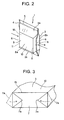
FIG. 2 is a perspective view illustrating the packaging bag in which a framework member is kept in an expanded state and a main bag body is deformed accordingly; -
FIG. 3 is a partial perspective view illustrating the packaging bag in which the lower portion of the main bag body, projecting downward from the lower end of the framework member is folded to form a bottom; -
FIG. 4 is a perspective view illustrating the packaging bag provided with the bottom as shown inFIG. 3 ; -
FIG. 5 is a perspective view illustrating the packaging bag in which the upper portion of the main bag body, projecting upward from the upper edge of the framework member is folded into a flat state, after the packaging bag is filled with contents; -
FIG. 6 is a perspective view illustrating the packaging bag in which the opposite edges of the upper portion of the main bag body, projecting horizontally from the upper edge of the framework member as shown inFIG. 5 , are further folded so as to come into contact with the opposite sides of the packaging bag, respectively, thus providing a rectangular parallelepiped; -
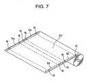
FIG. 7 is a perspective view illustrating a strip of plastic film for forming the main bag body, on which a set of male members and a set of female members for forming a linear fastener are provided while unrolling the strip of plastic film; -
FIG. 8 is a schematic perspective view illustrating a pair of strips of plastic film material for forming the framework member, which are subjected to a bending facilitation portion forming step to form bending facilitation portions thereon and then traveled so as to face each other; -
FIG. 9 is a partial cross-sectional view illustrating a roller having a projection, which is used to carry out the bending facilitation portion forming step and a resultant bending facilitation portion formed on the strip of plastic film by means of the projection; -
FIG. 10 is a schematic perspective view illustrating a step for folding the single strip for the main bag body with the pair of strips for the framework member in two along the longitudinal central line of the single strip for the main bag body; -
FIG. 11 is a schematic descriptive view illustrating a step for thermally bonding a folded composite strip of the single strip for the main bag body and the pair of strips for the framework member in a perpendicular direction to a longitudinal direction thereof by predetermined intervals to form heat-sealed portions; -
FIG. 12 is a schematic descriptive view illustrating a step for cutting each of the heat-sealed portions in two in the perpendicular direction to the longitudinal direction of the folded composite strip; -
FIG. 13 is a perspective view illustrating the packaging bag manufactured by the other method. -
FIG. 14 is a perspective view illustrating the packaging bag as shown inFIG. 13 , which is turned upside down; -
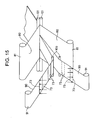
FIG. 15 is a schematic perspective view illustrating a step for continuously feeding a pair of strips of plastic film material for the main bag body, while continuously feeding a pair of strips of thin sheet material for the framework member to place the pair of strips for the framework member on the respective inner surfaces of the pair of strips for the main bag body; -
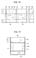
FIG. 16 is a schematic descriptive view illustrating a step for thermally bonding a set of composite strips of the pair of strips for the main bag body and the pair of strips for the framework member in a perpendicular direction to a longitudinal direction thereof by predetermined intervals to form side heat-sealed portions, a step for thermally bonding the set of composite strips on one of longitudinal edges of the set of composite strips to form a bottom heat-sealed portion, and a step for cutting each of the heat-sealed portions in two in the perpendicular direction to the longitudinal direction of the set of composite strips; -
FIG. 17 is a plan view illustrating the packaging bag kept in a flat collapsed state, which is manufactured through completion of the steps as shown inFIG. 16 ; -
FIG. 18 is a schematic sectional view illustrating the modification of the method for manufacturing the packaging bag of the present invention in which a set of three packaging bags can be provided in a region of the set of composite strips, which extends in the perpendicular direction to the feeding direction of the set of composite strips; -
FIG. 19 is a schematic descriptive view illustrating a series of steps of the modification as shown inFIG. 18 ; -
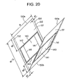
FIG. 20 is a schematic descriptive view illustrating the method for manufacturing the packaging bag of the present invention, which utilizes a single piece of plastic film for the main bag body and a pair of pieces of thin sheet material for the framework member in order to manufacture the single packaging bag; -
FIG. 21 is a schematic descriptive view illustrating the method for manufacturing the packaging bag of the present invention, which utilizes a pair of pieces of plastic film for the main bag body and a pair of pieces of thin sheet material for the framework member in order to manufacture the single packaging bag; and -
FIG. 22 is a schematic descriptive view illustrating the method for manufacturing the packaging bag of the present invention, which utilizes a pair of pieces of plastic film for the main bag body and a sleeve serving as the framework member in order to manufacture the single packaging bag. - Embodiments of the present invention will be described below with reference to the drawings.
-
FIG. 1 is a front view of apackaging bag 1 according to an embodiment of the present invention. Thepackaging bag 1 is composed of amain bag body 2 and aframework member 10, which is joined to themain bag body 2 prior to completion of a formation process thereof and is foldable/unfoldable together with themain bag body 2, to enable theframework member 10 and themain bag body 2 to be shifted between a generally flat collapsed state and an expanded state. - More specifically, the
main bag body 2 is made of plastic film material through a main bag body formation process in a rectangular shape in a generally flat collapsed state. Themain bag body 2 is formed by folding a single rectangular piece of plastic film material for the main bag body in two along the central line to form a pair ofopposite panel members portions main bag body 2 has an opening at an opposite side to the central line along which the above-mentioned piece is folded in two. Themain bag body 2 is provided at the opening with alinear fastener 5. Thelinear fastener 5 is composed of amale member 5a formed on the inner surface of one of thepanel members female member 5b formed on the inner surface of the other of thepanel members male member 5a can engage with or disengage from thefemale member 5b so as to close or open the upper end of themain bag body 2. - The
framework member 10 is made of thin sheet material such as plastic material or plastic/paper composite material. Theframework member 10 is composed of a pair of opposite reinforcing sections, which are thermally bonded to the inner surfaces of thepanel members panel member 3 is made so as to keep a distance "L1" between thelower edge 13 of the reinforcing section and the lower edge of thepanel member 3 and a distance "L2" between theupper edge 12 of the reinforcing section and the upper edge of thepanel member 3, as shown inFIG. 1 . Each of the reinforcing sections has the first pair of opposite side edges (i.e., the right and left hand side edges inFIG. 1 ) and the second pair of opposite side edges (i.e., the upper and lower side edges inFIG. 1 ). The length of each of the upper and lower side edges of the reinforcing section is substantially identical to the width of themain bag body 2 so that the right and left hand side edges of the reinforcing section are embedded in the side heat-sealedportions panel members portions - Each of the reinforcing sections of the
framework member 10 is provided at positions shifted inward from the right and left hand side edges of themain bag body 2 with a pair of bendingfacilitation portions portions facilitation portion 11 enables the reinforcing section to be easily bent along it, thus ensuring a folding/unfolding operation of theframework member 10. - The
male member 5a of thelinear fastener 5 is composed of three sections, i.e., a set of a central main section and opposite side sections, which are placed in line so as to be apart from each other, as shown inFIG. 7 . Gaps between the central main section and the opposite side sections are placed so as to correspond to the above-mentioned bending facilitation portions. Thefemale member 5b of thelinear fastener 5 is also composed of three sections in the similar manner as themale member 5a. The gaps of each of themale member 5a and thefemale member 5b enable themain bag body 2 to be easily folded in accordance with the shift of theframework member 10 between the collapsed state and the expanded state. - The
main bag body 2 and theframework member 10 are designed so that the height of theframework member 10 is substantially identical to the height of thepackaging bag 1, which is shifted to an expanded state and subjected to a bending finishing step to provide a finished product in the form of a rectangular parallelepiped. Theframework member 10 is bent at right angles at the bendingfacilitation portions - Now, description will be given below of the plastic film material for the
main bag body 2 and the thin sheet material for theframework member 10. - A plastic laminate film having a plurality of layers is used to form the
main bag body 2. There may be used, for example, a laminate film having a layer structure of an oriented polypropylene (OPP) layer having a thickness of 25µm and a polyethylene (PE) layer having a thickness of 50µm, which are thermally bonded to each other. In this case, themain bag body 2 is designed so that the oriented polypropylene layer is placed on the inner side of themain bag body 2. It is preferable to add an aluminum layer to the laminate film in order to improve barrier property. In this case, there may be used a laminate film having a layer structure of an oriented polypropylene (OPP) layer having a thickness of 25µm, an aluminum layer having a thickness of 5µm, and a polyethylene (PE) layer having a thickness of 50µm, which are thermally bonded to each other. - A plastic film having a predetermined strength that enables the predetermined shape into which the
main bag body 2 is shifted together with theframework member 10 in an expanded state, to be appropriately maintained is used to form theframework member 10. A polyethylene (PE) film having a thickness of 100µm is for example used for theframework member 10. - The
packaging bag 1 having the above-described structure is shifted from the generally flat collapsed state as shown inFIG. 1 to the expanded finished state as shown inFIG. 6 through the intermediate states as shown inFIGS. 2 to 5 . - First, the opposite sides of the
packaging bag 1, which is kept in the generally flat collapsed state, are pushed inwardly in directions as shown by arrows inFIG. 2 , with the result that the pair of opposite reinforcing sections of theframework member 10 are folded at right angles along the bendingfacilitation portions framework member 10 together with themain bag body 2 from the generally flat collapsed state to the expanded state in the form of sleeve. Such a pushing operation provides opposite front andrear panel portions side panel portions upper portion 3a, which upwardly projects from theupper edge 12 of theframework member 10, and alower portion 3b, which downwardly projects from thelower edge 13 of theframework member 10. In such a pushing operation, the side heat-sealedportions - Then, the
lower portion 3b downwardly projecting from thelower edge 13 of theframework member 10 is folded along thelower edge 13 of theframework member 10 into a flat state so as to provide a pair oftriangular portions FIG. 2 . Thetriangular portions framework member 10 and thermally bonded to the counterpart, as shown in solid lines inFIG. 3 , to form abottom panel portion 7 of thepackaging bag 1. Any other suitable bonding may be applicable to the bonding of thetriangular portions portions lower portion 3b of thepackaging bag 1 to form thebottom panel portion 7 is completed in this manner. At this stage, thepackaging bag 1 is provided on its lower side with the lower portion, which is folded into a box with a flat bottom having a rectangular shape, on its upper side with theupper portion 3a, which upwardly projects from the upper edge of theframework member 10 and is kept in a semi-folded state in which the width of theupper portion 3a of thepackaging bag 1 in its plan view gradually increases with its height, as shown inFIG. 4 . - Then, the
upper portion 3a, which upwardly projects from the upper edge of theframework member 10, is also folded along theupper edge 12 of theframework member 10 into a flat state so as to provide a pair oftrapezoidal portions FIG. 5 . In such a folding operation, the opening of thepackaging bag 1, which is closed by thelinear fastener 5, is brought close to therear panel portion 8b. - The above-mentioned pair of
trapezoidal portions framework member 10 and thermally bonded to the oppositeside panel portions FIG. 6 . The folding process of theupper portion 3a of thepackaging bag 1 to form thetop panel portion 9 is completed in this manner. Any other suitable bonding may be applicable to the bonding of thetrapezoidal portions portions side panel portions packaging bag 1 is filled with contents. - The
packaging bag 1, which is shifted from the generally flat collapsed state to the expanded state, this providing an external appearance of the box, has the opposite front andrear panel portions side panel portions rear panel portions bottom panel portion 7 that has been formed by folding thebottom portion 3b of thepackaging bag 1 in the flat state, and thetop panel portion 9 that has been formed by folding theupper portion 3a of thepackaging bag 1 in the flat state. The height of each of the front andrear panel portions side panel portions framework member 10, which is provided in thepackaging bag 1. More specifically, thelower edge 13 of theframework member 10 forms thecorners side panel portions bottom panel portion 7, on the one hand, and theupper edge 12 of theframework member 10 forms thecomers side panel portions top panel portion 9, on the one hand. In addition, the bent portions of theframework member 10, which are provided by bending theframework member 10 along the bendingfacilitation portions 11, form thecorners rear panel portions side panel portions - The
packaging bag 1 can be shifted from the generally flat collapsed state to the expanded state and then subjected to the folding processes to convert into a box shape, which corresponds to theframework member 10 kept in the expanded state. Accordingly, it is possible to receive products such as teabags having the predetermined shape in thepackaging bag 1 kept in the expanded state, without collapsing their shapes. Thelinear fastener 5, which is provided at the opening of thepackaging bag 1, makes thepackaging bag 1 reclosable even after opening thepackaging bag 1. - In the above-described
packaging bag 1 of the embodiment of the present invention, each of the upper and lower side edges of each of the reinforcing sections of theframework member 10 is thermally bonded to the inner surface of each of the panel members, 3, 3 at the other regions than the side heat-sealedportions framework member 10 is may not necessarily bonded to the inner surface of each of thepanel members portions panel members panel members packaging bag 1 with contents. - The above-described
packaging bag 1 of the embodiment of the present invention is provided with thelinear fastener 5. - Now, a first method for manufacturing the above-described
packaging bag 1 will be described below with reference toFIGS. 7 to 12 . - In the first method, the
single strip 20 for themain bag body 2 and the pair ofstrips framework member 10 are used to manufacture the plurality ofpackaging bags 1. - More specifically, the method for manufacturing the
packaging bag 1 includes the essential steps of: - (1-a) continuously feeding a
single strip 20 of plastic film material for themain bag body 2 in a longitudinal direction, thesingle strip 20 having opposite half portions between which a longitudinal central line of thesingle strip 20 exists; - (1-b) continuously feeding a pair of
strips framework member 10 to place the pair ofstrips framework member 10 on a surface of thesingle strip 20 for themain bag body 2 in predetermined positions of the respective opposite half portions of thesingle strip 20; - (1-c) bonding the pair of
strips framework member 10 to thesingle strip 20 for themain bag body 2 in respective opposite half portions thereof; - (1-d) folding the
single strip 30 for themain bag body 3 with the pair ofstrips framework member 10 in two along the longitudinal central line of thesingle strip 20 for themain bag body 2 to bring one of the opposite half portions of thesingle strip 20 for themain bag body 2 close to another of the opposite half portions to prepare a folded composite strip so that the pair ofstrips framework member 10 are placed in an inside of the folded composite strip; - (1-e) thermally bonding the folded composite strip in a perpendicular direction to a longitudinal direction thereof by predetermined intervals to form heat-sealed
portions 4•••4; and - (1-f) cutting each of the heat-sealed
portions 4•••4 in two in the perpendicular direction to the longitudinal direction of the folded composite strip, - (1-g) prior to the step (1-b), forming bending
facilitation portions 11•••11 on each of the pair ofstrips strips framework member 10; and - (1-h) during the step (1-a), providing a set of
male members 5a and a set offemale members 5b in each of the respective consecutive regions for the packaging bags on the single strip for themain bag body 2. - First, the step (1-a) is carried out to unroll the
single strip 20 of plastic film material for themain bag body 2 to continuously feed it in the longitudinal direction. Thesingle strip 20 has the opposite half portions between which the longitudinal central line of thesingle strip 20 exists. The layer structure of thesingle strip 20 of plastic film material for themain bag body 2 is the same as that of themain bag body 2 of thepackaging bag 1 of the present invention as described above and description of the layer structure is therefore omitted. - The step (1-h) is carried out to continuously provide a plurality of sets of
male members 5a and a plurality of corresponding sets offemale members 5b on the longitudinal opposite side edge portions of the upper surface of thesingle strip 20 for themain bag body 2, so as to form thesemembers single strip 20 through an insert injection. Agap 15 exists between the adjacent sets ofmale members 5a and anothergap 15 also exists between the adjacent sets offemale members 5b corresponding to the above-mentionedgap 15. The correspondinggaps FIG. 7 , which is perpendicular to the feeding direction of thesingle strip 20 for themain bag body 2. Thesingle strip 20 will be cut along the above-mentioned straight line into pieces for the respectivemain bodies 2. Each set ofmale members 5a is composed of a central main section and opposite side sections, which are placed in line so as to be apart from each other, as shown inFIG. 7 .Gaps 16•••16 between the central main section and the opposite side sections are placed so as to correspond to the bendingfacilitation portions 11•••11 as described later. Each set offemale members 5b is also composed of three sections in the similar manner as the set ofmale members 5a. The set ofmale members 5a can be engaged with or removed from the set offemale members 5b. - The step (1-b) is carried out to unroll the pair of
strips framework member 10 from a pair of rolls, which is disposed on the left-hand side ofFIG. 8 , but not shown therein, to continuously feed them in their longitudinal directions to place them on the surface of thesingle strip 20 for themain bag body 2 in the predetermined positions of the respective half portions. - More specifically, the
strips framework member 10 are unrolled at the different positions from each other and fed together in a prescribed zone, thus traveling in parallel with each other in their longitudinal directions. Before the pair ofstrips framework member 10 reaches the above-mentioned prescribed zone, the step (1-g) is carried out to form the bendingfacilitation portions 11•••11 on the opposite inner surfaces of the pair ofstrips framework member 10 so as to extend in the perpendicular direction to the feeding direction of the pair ofstrips framework member 10. The bendingfacilitation portions 11•••11 are classified into a plurality of pairs of bendingfacilitation portions strips framework member 10. The adjacent pairs of bendingfacilitation portions strips facilitation portions bending facilitation portions - The pair of reinforcing sections is used for the
single packaging bag 1 so that the central portions of the pair of reinforcing sections define the opposite front andrear panel portions packaging bag 1 as shown inFIG. 6 , respectively, and the combinations of the corresponding side portions of the pair of reinforcing sections define theside panel portions packaging bag 1, respectively. -
FIG. 9 shows a typical device for carrying out the above-mentioned step (1-g) to form the bendingfacilitation portions 11•••11 on each of the pair ofstrips framework member 10. The device is composed of aroller 40 provided with aprojection 41 formed on the periphery thereof. Theprojection 41 extends over theroller 40 in its longitudinal direction. The central axis of theroller 40 is perpendicular to the feeding direction of thestrip 30 for theframework member 10. A base plate (not shown) is disposed so as to face theroller 40 and extend along it in its longitudinal direction. The distance between the base plate and the outer peripheral surface of theroller 40 is substantially identical or smaller than the thickness of thestrip 30 for theframework member 10. The above-mentioned base plate may be substituted by another roller having no projection. - The
strip 30 passes through between the base plate and theroller 40 to dig theprojection 41 into thestrip 30, thus forming a groove serving as the bendingfacilitation portion 11, which extends in the perpendicular direction to the feeding direction of thestrip 30. A set of rollers, i.e., the above-mentionedroller 40 and the other roller having the same structure, which are disposed so as to be away from each other by a predetermined distance, are utilized to form the above-described plurality of pairs of bendingfacilitation portions 11•••11 on one of the pair ofstrips framework member 10. The other set of rollers having the same structure are utilized to form the plurality of pairs of bendingfacilitation portions 11•••11 on the other of the pair ofstrips framework member 10. According to these sets of rollers, it is possible to continuously form the plurality of pairs of bendingfacilitation portions 11•••11 on the pair ofstrips framework member 10, without halting the feeding of thestrips - The device for carrying out the step (1-g) is not limited only to the above-mentioned roller type. For example, an elongated pushing block having a longitudinal edge may be used to form the bending
facilitation portions 11•••11 on thestrip 30 for theframework member 10. In this case, the feeding of thestrip 30 is intermittently halted and the pushing block is pressed against thestrip 30 to form the bendingfacilitation portion 11 during the halting period of time. - The pair of
strips framework member 10, on which the bendingfacilitation portions 11•••11 have been formed by carrying out the step (1-g), is continuously fed, during the step (1-b), to place them on the inner surface of thesingle strip 20 for themain bag body 2 in the respective opposite half portions thereof. - The step (1-c) is carried out to thermally bond the pair of
strips single strip 20 for themain bag body 2 in respective opposite half portions thereof. - Then, the step (1-d) is carried out to fold the
single strip 30 for themain bag body 3 with the pair ofstrips framework member 10 in two along the longitudinal central line of thesingle strip 20 for themain bag body 2 to bring one of the opposite half portions of thesingle strip 20 for themain bag body 2· close to another of the opposite half portions to prepare a folded composite strip so that the pair ofstrips framework member 10 are placed in an inside of the folded composite strip, as shown inFIG. 10 . In the step (1-d), the set ofmale members 5a is engaged with the set of thefemale members 5b. Of course, the step (1-d) may be carried out, while conducting the steps (1-a), (1-b) and (1-c). - As is clear from
FIG. 10 , the positional determination of each of thestrips lower edge 13 of the folded composite strip and the lower edge of each of thestrips upper edge 12 of the each of thestrips 30. 30 and the upper edge of the folded composite strip. The lower portion of the folded composite strip, which corresponds to the distance "L1", is used to form thebottom panel portions 7 of thepackaging bags 1, as shown inFIG. 3 . The upper portion of the folded composite strip, which corresponds to the distance "L2", is used to form thetop panel portions 9 of thepackaging bags 1, as shown inFIG. 6 . - The step (1-e) is carried out to thermally bond the folded composite strip in a perpendicular direction to the longitudinal direction thereof by predetermined intervals to form heat-sealed
portions 4•••4, as shown inFIG. 11 . Such a thermal bonding process is conducted with the use of a heat-sealing plate, which is brought into contact with the outer surface of the folded composite strip. The portions of the folded composite strip, to which the thermal bonding process is to be applied, correspond to the respective central lines between the adjacent pairs of bendingfacilitation portions - Then, the step (1-f) is carried out to cut each of the heat-sealed
portions 4•••4 in two in the perpendicular direction to the longitudinal direction of the folded composite strip, thereby continuously manufacturing the plurality ofpackaging bags 1. In each of thepackaging bags 1, the opposite side edges of the reinforcing section, which are in parallel with the bendingfacilitation portions portions - In the above-described method, the steps (1-a) to (1-h) are carried out on the manufacturing line. The steps (1-a) to (1-h) may however be carried out independently each other on the different manufacturing lines.
- In the above-described method, each of the bending
facilitation portions 11•••11 provided by the step (1-g) is formed into a groove. The bendingfacilitation portion 11 may have any other structure that enables the reinforcing section, which is obtained by cutting thestrip 30, to be easily bent along the bendingfacilitation portion 11. The bendingfacilitation portion 11 may for example be provided in the different form for example of perforations. - In the above-described method, the insert injection is applied to carry out the step (1-h). The
male members 5a and thefemale members 5b, which have been previously formed through extrusion, may however be bonded to thesingle strip 20 for themain bag body 2. - The above-described method includes the step (1-h) to provide the sets of
male members 5a and the sets offemale members 5b on thesingle strip 20 for themain bag body 2. The step (1-h) may however be omitted, as an occasion demands. - Now, the second method for manufacturing the above-described
packaging bag 1 will be described below with reference toFIGS. 13 to 17 . -
FIGS. 13 and 14 illustrate thepackaging bag 50 manufactured by the second method. Thepackaging bag 50 is different from thepackaging bag 1 as shown inFIGS. 1 to 6 in that the former has a heat-sealed portion on the bottom panel portion. Thepackaging bag 50 is composed of amain bag body 60 formed of plastic film material and aframework member 70, which is joined to themain bag body 60 prior to completion of the formation process thereof. Aframework member 70 is folded along bendingfacilitation portions 73···73 formed thereon into a rectangular parallelepiped, with the result that themain bag body 60 is also folded into the similar shape. After thepackaging bag 50 is filed with contents, the upper portion of themain bag body 60 is folded along theupper edge 71 of theframework member 70 into a flat state to form an overlappedportion 61a. The overlappedportion 61a is then bent toward therear panel portion 52 to provide a pair oftrapezoidal portions trapezoidal portions framework member 70 and thermally bonded to the oppositeside panel portions FIG. 13 . The folding process of the upper portion of thepackaging bag 50 to form thetop panel portion 62 is completed in this manner. Any other suitable bonding may be applicable to the bonding of thetrapezoidal portions portions side panel portions packaging bag 50 is filled with contents. -
FIG. 14 is a perspective view of thepackaging bag 50, which is folded and then subjected to the additional folding process to provide the finished product, illustrating the bottom of thepackaging bag 50. When thepackaging bag 50 is shifted from a generally flat collapsed state to the expanded state, the lower portion of thepackaging bag 50 downwardly projects from thelower edge 72 of theframework member 70. The above-mentioned lower portion, which has a bottom heat-sealedportion 57 formed on the lowermost edge thereof so as to extend in the width direction of thepackaging bag 50, is folded along thelower edge 72 of theframework member 70 into a flat state so as to provide a pair oftriangular portions triangular portions portion 57, respectively, are bent inwardly along thelower edge 72 of theframework member 70 and thermally bonded to the counterpart, as shown in solid lines inFIG. 14 , to form abottom panel portion 63 of thepackaging bag 50. Any other suitable bonding may be applicable to the bonding of thetriangular portions portions packaging bag 50 to form thebottom panel portion 63 is completed in this manner. - Now, a second method for manufacturing the above-described
packaging bag 50 will be described below with reference toFIGS. 15 to 17 . - In the second method, the pair of
strips main bag body 60 and the pair ofstrips framework member 10 are used to manufacture the plurality ofpackaging bags 50. - More specifically, the method for manufacturing the
packaging bag 50 includes the essential steps of: - (2-a) continuously feeding a pair of
strips main bag body 60 in a longitudinal direction so as to be apart from each other; - (2-b) continuously feeding a pair of
strips framework member 70 to place the pair ofstrips framework member 70 on respective inner surfaces of the pair ofstrips main bag body 60 in predetermined positions thereof; - (2-c) bonding the pair of
strips framework member 70 to the pair ofstrips main bag body 60, respectively; - (2-d) bringing one of the pair of
strips main bag body 60 close to another of the pair ofstrips main bag body 60 so as to cause the pair ofstrips framework member face 70 each other, thus preparing a set of composite strips; - (2-e) thermally bonding the set of composite strips in a perpendicular direction to a longitudinal direction thereof by predetermined intervals to form side heat-sealed
portions 56···56; - (2-f) thermally bonding the set of composite strips on the lower longitudinal edges of the set of composite strips to form a bottom heat-sealed
portion 57; and - (2-g) cutting each of the side heat-sealed
portions 56•••56 in two in the perpendicular direction to the longitudinal direction of the set of composite strips, - (2-i) prior to said step (2-b), forming bending
facilitation portions 73•••73 on each of the pair ofstrips framework member 70 so as to extend in a perpendicular direction to a feeding direction of the pair ofstrips framework member 70; and - (2-j) during the step (2-a), providing a set of male members (not shown) and a set of female members (not shown) in each of the respective consecutive regions for the packaging bags on the pair of
strips main bag body 60. - First, the step (2-a) is carried out to unroll the pair of
strips main bag body 60 from the rolled strips 81, 8a to continuously feed them in the longitudinal direction so as to be apart from each other. Thestrips rollers FIG. 15 . The layer structure of each of thestrips main bag body 60 is the same as that of themain bag body 2 of thepackaging bag 1 of the present invention as described above and description of the layer structure is therefore omitted. - The step (2-j) is carried out to continuously provide a set of male members (not shown) and a set of female members (not shown) in each of the respective consecutive regions for the packaging bags on the pair of
strips main bag body 60. The step (2-j) is carried out on the upstream side of the above-mentionedpressing rollers strips main bag body 60. The step (2-j) is identical to the step (1-h) described above of the first embodiment of the method of the present invention and the detailed description of the step (2-j) is therefore omitted. - The step (2-b) is carried out to unroll the pair of
strips framework member 70 from the rolled strips 91, 91 to place them between the pair ofstrips main bag body 60 so that the pair ofstrips framework member 70 is located on respective inner surfaces of the pair ofstrips main bag body 60 in predetermined positions thereof. As a result, the pair ofstrips framework member 70 passes through between the above-mentionedpressing rollers strips main bag body 60 to carry out the step (2-d) to bring one of the pair ofstrips main bag body 60 close to another of the pair ofstrips main bag body 60 so as to cause the pair ofstrips framework member face 70 each other, thus preparing a set of composite strips. The pair ofstrips framework member 70 is guided by means of a pair ofguide rollers FIG. 15 . The layer structure of each of thestrips framework member 70 is the same as that of theframework member 10 of thepackaging bag 1 of the present invention as described above and description of the layer structure is therefore omitted. - As is clear from
FIG. 16 , the positional determination of each of thestrips main bag body 60 is made so as to keep a distance "L4" between the lower edge of thestrips main bag body 60 and the lower edge of each of thestrips strips 90. 90 and the upper edge of thestrips main bag body 60. The lower portion of thestrips main bag body 60, which corresponds to the distance "L4", is used to form thebottom panel portions 55 of thepackaging bags 50, as shown inFIG. 14 . The upper portion of thestrips main bag body 60, which corresponds to the distance "L3", is used to form thetop panel portions 53 of thepackaging bags 50, as shown inFIG. 13 . - Before the pair of
strips framework member 70 reaches the above-mentionedguide rollers facilitation portions 73•••73 on the opposite inner surfaces of the pair ofstrips framework member 70 so as to extend in the perpendicular direction to the feeding direction of the pair ofstrips framework member 70. The step (2-i) is identical to the step (1-g) described above of the first embodiment of the method of the present invention and the detailed description of the step (2-i) is therefore omitted. - The step (2-c) is carried out to thermally bond the pair of
strips framework member 70 on the opposite longitudinal edge portions thereof to the pair ofstrips main bag body 60, respectively. The step (2-c) is conducted on the downstream side of thepressing rollers strips main bag body 60. - In addition, the step (2-e) is carried out to thermally bond the combination of the pair of
strips main bag body 60 with the pair ofstrips framework member 70, i.e., the set of composite strips in a perpendicular direction to the longitudinal direction thereof by predetermined intervals to form side heat-sealedportions 56•••56. - The step (2-f) is also carried out to thermally bond the set of composite strips on the lower longitudinal edges of the set of composite strips to form a bottom heat-sealed
portion 57. - Then, the step (2-g) is carried out to cut each of the side heat-sealed
portions 56···56 in two in the perpendicular direction to the longitudinal direction of the set of composite strips, thereby continuously manufacturing the plurality ofpackaging bags 50. In each of thepackaging bags 50, the opposite side edges of the reinforcing section of theframework member 70, which are in parallel with the bendingfacilitation portions portions FIG. 17 . - In the above-described method, the steps (2-a) to (2-j) are carried out on the manufacturing line. The steps (2-a) to (2-j) may however be carried out independently each other on the different manufacturing lines.
- In the above-described second method, the step (2-i) may be modified in the same manner as the step (1-g) of the method of the first embodiment of the present invention.
- In the above-described second method, the step (2-j) may be modified in the same manner as the step (1-h) of the first method.
- The above-described second method includes the step (2-j) to provide the sets of
male members 5a and the sets offemale members 5b on the pair ofstrips main bag body 60. The step (2-j) may however be omitted, as an occasion demands. - In the above-described second method, the width of the pair of
strips main bag body 60 is substantially identical to the height of thepackaging bag 50. Accordingly, each of the consecutive steps (2-g), i.e., the single cutting operation provides thesingle packaging bag 50. However, there may be adopted a modification in which the width of each of the pair ofstrips main bag body 60 is increased so that a plurality ofmain bag bodies 60 can be allocated in a region of thestrip 80, which extends over the entire width thereof, on the one hand, and a plurality of pairs ofstrips framework member 70 is fed, on the other hand. - Now, description will be given of an example of such modification in which three main bag bodies are allotted in a region of the
strip 80, which extends over the entire width thereof, with reference toFIGS. 18 and 19 . -
FIG. 18 is a schematic sectional view illustrating the modification of the method, in which a set of three packaging bags can be provided in a region of the set of composite strips, which extends in the perpendicular direction to the feeding direction of the set of composite strips. The horizontal direction inFIG. 18 corresponds to the width direction, i.e., the perpendicular direction to the feeding direction of the pair ofstrips - Each of the pair of
strips packaging bag 50 to be manufactured. Thesestrips - Three pairs of
strips strips strips strips - The opposite
longitudinal edge portions respective strips 120 are thermally bonded to thecorresponding strip 110 for the main bag body, and then one of the pair ofstrips strips FIG. 19 . - Then, the set of composite strips are thermally bonded in the longitudinal direction at three positions, i.e., the lowermost position of the set of composite strips as shown in
FIG. 19 and the additional two positions, which divide the set of composite strips in the width direction (i.e., the vertical direction inFIG. 19 ) into three equal parts, to form three bottom heat-sealedportions FIG. 19 . - In addition, the set of composite strips are thermally bonded in a perpendicular direction to the longitudinal direction thereof by predetermined intervals to form side heat-sealed
portions 112•••112 in the similar manner to the step (2-e) of the above-described second embodiment of the method of the present invention, as shown in the third region between the two-dot chain straight lines "A3" and "A4" inFIG. 19 . Each of the thus formed side heat-sealedportions 112•••112 extends over the set of composite strips in the width direction thereof. Areas defined by the bottom heat-sealedportions portions 112•••112 are to form the respective packaging bags. - Then, the set of composite strips thus heat-sealed are cut in the longitudinal direction at two positions into three semi-finished strips for the packaging bags, as shown in the fourth region between the two-dot chain straight lines "A4" and "A5" in
FIG. 19 . These two positions are located directly below the above-mentioned additional two positions for the thermal bonding, which divide the set of composite strips in the width direction into three equal parts, as shown inFIG. 19 . As a result, the resultant three semi-finished strips for the packaging bags have substantially the same width. Each of the thus prepared semi-finished strips for the packaging bags is formed into a chain of packaging bags. The above-described second embodiment of the method of the present invention does not include such a cutting step. - Then, each of the semi-finished strips for the packaging bags is subjected to a further cutting step to cut each of the side heat-sealed
portions 112•••112 in two in the perpendicular direction to the longitudinal direction of the semi-finished strip, thereby manufacturing a plurality of independent packaging bags. - The above-described modification of the method makes it possible to improve remarkably the manufacturing efficiency.
- The above-described methods and the modification thereof provide the continuous manufacture of the plurality of packaging bags. The method may be worked in the form of batch manufacturing system in a manner as described below.
- Now, the third method for manufacturing the above-described packaging bag will be described below with reference to
FIG. 20 . - In the third method, the single piece for the main bag body and the pair of
pieces - More specifically, the method for manufacturing the packaging bag includes the essential steps of:
- (3-a) preparing a single piece of plastic film material for a main bag body, the single piece having opposite
half portions central line 130b of the single piece exists; - (3-b) placing a pair of
pieces opposite half portions - (3-c) bonding the pair of
pieces opposite half portions - (3-d) folding the single piece for the main bag body with the pair of pieces for the framework member in two along the
central line 130b of the single piece for the main bag body to bring one of theopposite half portions opposite half portions pieces - (3-e) thermally bonding the folded composite piece on opposite sides thereof to form heat-sealed portions,
- (3-f) prior to the step (b), forming bending facilitation portions on each of the pair of pieces for the framework member; and
- (3-g) providing a set of male members (not shown) and a set of female members (not shown) in each of the opposite longitudinal sides of the single piece for the main bag body so as to extend in the width direction thereof.
- First, the step (3-a) is carried out to prepare the single piece of plastic film material for the main bag body. Such a piece for the main bag body is formed into a rectangular shape provided with a long side having a length of "M" and a short side having a length of "N".
FIG. 20 illustrates the piece for the main bag body, which is semi-folded in two, with the result thatFIG. 20 includes the indication of "M/2". The piece for the main bag body has theopposite half portions central line 130b of the single piece exists. The layer structure of the piece for themain bag body 60 is the same as that of themain bag body 2 of thepackaging bag 1 of the present invention as described above and description of the layer structure is therefore omitted. - The step (3-g) is carried out to provide a set of male members (not shown) and a set of female members (not shown) on the respective half portions of the piece for the main bag body so as to extend in the width direction on the opposite portions of the long side of the piece for the main bag body. The step (3-g) is similar to the step (1-h) described above of the first embodiment of the method of the present invention and the detailed description of the step (3-g) is therefore omitted.
- The pair of
pieces pieces portion 132 to be thermally bonded of the piece for the main bag body, as shown inFIG. 20 . The layer structure of each of thepieces framework member 10 of thepackaging bag 1 of the present invention as described above and description of the layer structure is therefore omitted. - The thus prepared
pieces facilitation portions 141 on each of the pair ofpieces pieces facilitation portion 141 extends in parallel to the right-hand and left-hand side edges of thepiece 140 for the framework member, as shown inFIG. 20 . - Then, the step (3-b) is carried out to place the pair of
pieces opposite half portions piece 140 is placed on thehalf portion 131 in the predetermined position so as to keep a distance "M1" between theupper edge 142 of thepiece 140 and one of the opposite short side edges of the single piece for the main bag body and a distance "M2" between the lower edge of thepiece 140 and thecentral line 130b of the single piece. The same positional determination of thepiece 140 relative to thehalf portion 131 of the single piece for the main bag body is also made on theother half portion 131 thereof. - Then, the step (3-c) is carried out to thermally bond the pair of
pieces opposite half portions pieces FIG. 20 to therespective half portions - Then, the step (3-d) is carried out to fold the single piece for the main bag body with the pair of
pieces central line 130b of the single piece for the main bag body to bring one of theopposite half portions opposite half portions pieces - Then, the step (3-e) is carried out to thermally bond the folded composite piece on opposite sides thereof, i.e., at the
portions pieces section 140 and the upper and lower side edges (i.e., the second pair of opposite side edges) thereof are thermally bonded to the main bag body at other regions than the pair of side heat-sealed portions. - The packaging bag is shifted to an expanded state and subjected to a bending finishing step to provide a finished product in the form of a rectangular parallelepiped in the same manner as the packaging bag as described above and illustrated in
FIGS. 1 to 6 . - Now, the fourth method for manufacturing the packaging bag will be described below with reference to
FIG. 21 . - In the fourth method, the pair of
pieces pieces - More specifically, the method for manufacturing the packaging bag includes the essential steps of:
- (4-a) placing a pair of
pieces - (4-b) placing a pair of
pieces pieces - (4-c) bonding the pair of
pieces pieces - (4-d) bringing one of the pair of
pieces pieces pieces - (4-e) thermally bonding the set of composite pieces at opposite side edges and a bottom edge thereof to form side heat-sealed portions and a bottom heat-sealed portion;
- (4-f) prior to the step (b), forming bending facilitation portions on each of the pair of pieces for the framework member; and
- (4-g) providing a set of male members (not shown) and a set of female members (not shown) in each of the pair of
pieces - First, the step (4-a) is carried out to place the pair of
pieces pieces pieces main bag body 2 of thepackaging bag 1 of the present invention as described above and description of the layer structure is therefore omitted. - The step (4-g) is carried out to provide a set of male members (not shown) and a set of female members (not shown) in each of the pair of
pieces - The pair of
pieces pieces pieces portion 151 to be thermally bonded of the piece for the main bag body, as shown inFIG. 21 . The layer structure of each of thepieces framework member 10 of thepackaging bag 1 of the present invention as described above and description of the layer structure is therefore omitted. - The thus prepared
pieces facilitation portions pieces pieces facilitation portion 161 extends in parallel to the right-hand and left-hand side edges of thepiece 160 for the framework member, as shown inFIG. 21 . - Then, the step (4-b) is carried out to place the pair of
pieces pieces piece 160 is placed on thepiece 150 in the predetermined position so as to keep a distance "P1" between theupper edge 162 of thepiece 160 and one of the opposite short side edges of thepiece 150 for the main bag body and a distance "P2" between the lower edge of thepiece 160 and the other the opposite short side edges of thepiece 150 for the main bag body. The same positional determination of thepiece 160 relative to the other piece for the main bag body is also made. - Then, the step (4-c) is carried out to thermally bond the pair of
pieces pieces pieces FIG. 21 to therespective pieces - Then, the step (4-d) is carried out to bring one of the pair of
pieces pieces pieces - Then, the step (4-e) is carried out to thermally bond the set of composite pieces at opposite side edges 151, 151 and a
bottom edge 151 thereof to form side heat-sealed portions and a bottom heat-sealed portion, thereby manufacturing the packaging bag. The thus manufactured packaging bag is composed of the main bag body formed of the pair ofpieces pieces section 160 and the upper and lower side edges (i.e., the second pair of opposite side edges) thereof are thermally bonded to the main bag body at other regions than the pair of side heat-sealed portions. - The packaging bag is shifted to an expanded state and subjected to a bending finishing step to provide a finished product in the form of a rectangular parallelepiped in the same manner as the packaging bag as described above and illustrated in
FIGS. 1 to 6 . - Now, the method for manufacturing the packaging bag will be described below with reference to
FIG. 22 . - In the fifth method , the pair of
pieces framework member 170, which is formed into a sleeve, are used to manufacture the single packaging bags. - More specifically, the method for manufacturing the packaging bag includes the essential steps of:
- (5-a) placing a pair of
pieces - (5-b) placing a
framework member 170, which is formed into a sleeve, on respective inner surfaces of the pair ofpieces - (5-c) bonding the
framework member 170 to the pair ofpieces - (5-d) bringing one of the pair of
pieces pieces framework 170 between the pair ofpieces - (5-e) thermally bonding the set of composite pieces at opposite side edges and a bottom edge thereof to form side heat-sealed portions and a bottom heat-sealed portion;
- (5-f) prior to the step (b), forming bending facilitation portions on the framework member; and
- (5-g) providing a set of male members (not shown) and a set of female members (not shown) in each of the pair of
pieces - First, the step (5-a) is carried out to place the pair of
pieces pieces pieces main bag body 2 of thepackaging bag 1 of the present invention as described above and description of the layer structure is therefore omitted. - The step (5-g) is carried out to provide a set of male members (not shown) and a set of female members (not shown) in each of the pair of
pieces - The
framework member 170 is prepared in the form of sleeve, which has openings on the upper and lower sides thereof. Theframework member 170, which is formed of a piece of plastic material, is composed of the pair of opposite reinforcing sections each having the same rectangular shape. The opposite reinforcing sections are combined to each other by means of a pair of bendingfacilitation portions framework member 170. In addition, each of the opposite reinforcing sections has the other pair of bendingfacilitation portions facilitation portions facilitation portions facilitation portions facilitation portions framework member 170 to be shifted between a generally flat collapsed state and an expanded state. The width of theframework member 170, which is kept in the generally flat collapsed state, is smaller than the width of each of thepieces side edge portion 181 to be thermally bonded of thepiece 180 for the main bag body, as shown inFIG. 22 . The layer structure of the plastic material for the framework member is the same as that of theframework member 10 of thepackaging bag 1 of the present invention as described above and description of the layer structure is therefore omitted. - The above-described
framework member 10 is obtained by carrying out the step (5-f) to form the bendingfacilitation portions framework member 170 and then the further additional step for bringing one edge of the above-mentioned piece for theframework member 170 close to the other edge thereof and combining these edges to each other. The step (5-f) is carried out in the similar manner as the step (1-g) described above of the first embodiment of the method of the present invention. The connection portion in which the opposite edges of the piece for theframework member 170 is connected to each other, may be designed to serve as one of the bendingfacilitation portions - Then, the step (5-b) is carried out to place the
framework member 170, which is kept in the generally flat collapsed state, on respective inner surfaces of the pair ofpieces framework member 170 is placed on thepiece 180 in the predetermined position so as to keep a distance "S1" between theupper edge 173 of theframework member 170 and one of the opposite short side edges of thepiece 150 for the main bag body and a distance "S2" between the lower edge of theframework member 170 and the other the opposite short side edges of thepiece 180 for the main bag body. The same positional determination of theframework member 170 relative to theother piece 180 for the main bag body is also made. - Then, the step (5-c) is carried out to thermally bond the
framework member 170 to the pair ofpieces framework member 170 is thermally bonded at its opposite peripheries as hatched inFIG. 22 to therespective pieces - Then, the step (5-d) is carried out to bring one of the pair of
pieces pieces framework 170 between the pair ofpieces - Then, the step (5-e) is carried out to thermally bond the set of composite pieces at opposite side edges 181, 181 and a
bottom edge 181 thereof to form side heat-sealed portions and a bottom heat-sealed portion, thereby manufacturing the packaging bag. The thus manufactured packaging bag is composed of the main bag body formed of the pair ofpieces framework member 170, i.e., the sleeve. Theportions pieces facilitation portions framework member 170 are placed to be adjacent. - The packaging bag is shifted to an expanded state and subjected to a bending finishing step to provide a finished product in the form of a rectangular parallelepiped in the same manner as the packaging bag as described above and illustrated in
FIGS. 1 to 6 . - According to the present invention described above, the packaging bag comprises the main bag body and the framework member, which is joined to the main bag body prior to completion of the main bag body formation process, it is possible to avoid problems when inserting the sleeve into the main bag body in accordance with the prior art so as to facilitate manufacture of the packaging bag, thus reducing the manufacturing cost. It is also possible to provide an excellent external appearance in the expanded state.
- According to the method, it is possible to manufacture the above-mentioned packaging bag in an effective manner.
Claims (5)
- A packaging bag comprising:a main bag body (2, 60) made of plastic film material through a main bag body formation process, said main bag body (2, 60) having an opening and a plurality of heat sealed portions (4, 4; 56, 56); anda framework member (10, 70, 140, 160, 170) wherein said framework member (10, 70, 140, 160, 170) is joined to said main bag body (2, 60) prior to completion of said main bag body formation process, said framework member (10, 70, 140, 160, 170) being foldable/unfoldable together with said main bag body (2, 60), to enable said framework member (10, 70, 140, 160, 170) and said main bag body (2, 60) to be shifted between a generally flat collapsed state and an expanded state, andsaid framework member (10, 70, 140, 160, 170) has openings on the upper and lower side thereof,wherebythe framework member (10, 70, 140, 160, 170) is disposed in said main bag body (2, 60), and characterized in thatthe packaging bag further comprises a linear fastener (5) provided on said opening of said main bag body (2, 60) whereby the framework member (10, 70, 140, 160, 170) is thermally bonded at the upper and lower edges thereof to the inner surface of the main bag body (2, 60).
- The bag as claimed in claim 1, wherein:said main bag body (2, 60) has a rectangular shape in a generally flat collapsed state, said main bag body (2, 60) being provided on opposite side edges thereof with a pair of heat-sealed portions (4, 4; 56, 56).
- The bag as claimed in claim 2, wherein:said framework member (10, 70, 140, 160) comprises a pair of opposite reinforcing sections, each of said reinforcing sections having a rectangular shape having first pair of opposite side edges and second pair of opposite side edges, said first pair of opposite side edges being embedded in said pair of heat-sealed portions (4, 4; 56, 56).
- The bag as claimed in claim 3, wherein:said second pair of opposite side edges is bonded to said main bag body (2, 60) at other regions than said pair of heat-sealed portions (4, 4; 56, 56).
- The bag as claimed in claim 2, wherein:said framework member (10, 70, 140, 160) comprises a pair of opposite reinforcing sections, each of said reinforcing sections having a rectangular shape having first pair of opposite side edges and second pair of opposite side edges, said pair of opposite side edges and said second pair of opposite side edges being thermally bonded to said main bag body (2, 60) at other regions than said pair of heat-sealed portions (4, 4; 56, 56).
Priority Applications (1)
| Application Number | Priority Date | Filing Date | Title |
|---|---|---|---|
| EP20080011272 EP1967460B1 (en) | 2002-11-27 | 2003-11-19 | Packaging bag and method for manufacturing same |
Applications Claiming Priority (2)
| Application Number | Priority Date | Filing Date | Title |
|---|---|---|---|
| JP2002343845A JP3965355B2 (en) | 2002-11-27 | 2002-11-27 | Packaging bag and manufacturing method thereof |
| JP2002343845 | 2002-11-27 |
Related Child Applications (1)
| Application Number | Title | Priority Date | Filing Date |
|---|---|---|---|
| EP20080011272 Division EP1967460B1 (en) | 2002-11-27 | 2003-11-19 | Packaging bag and method for manufacturing same |
Publications (3)
| Publication Number | Publication Date |
|---|---|
| EP1424290A2 EP1424290A2 (en) | 2004-06-02 |
| EP1424290A3 EP1424290A3 (en) | 2004-07-21 |
| EP1424290B1 true EP1424290B1 (en) | 2008-10-22 |
Family
ID=32290448
Family Applications (2)
| Application Number | Title | Priority Date | Filing Date |
|---|---|---|---|
| EP20080011272 Expired - Lifetime EP1967460B1 (en) | 2002-11-27 | 2003-11-19 | Packaging bag and method for manufacturing same |
| EP20030026606 Expired - Lifetime EP1424290B1 (en) | 2002-11-27 | 2003-11-19 | Packaging bag and method for manufacturing same |
Family Applications Before (1)
| Application Number | Title | Priority Date | Filing Date |
|---|---|---|---|
| EP20080011272 Expired - Lifetime EP1967460B1 (en) | 2002-11-27 | 2003-11-19 | Packaging bag and method for manufacturing same |
Country Status (6)
| Country | Link |
|---|---|
| US (2) | US20040101216A1 (en) |
| EP (2) | EP1967460B1 (en) |
| JP (1) | JP3965355B2 (en) |
| CN (1) | CN100408440C (en) |
| DE (1) | DE60324239D1 (en) |
| ES (1) | ES2315452T3 (en) |
Families Citing this family (37)
| Publication number | Priority date | Publication date | Assignee | Title |
|---|---|---|---|---|
| BRPI0511919A (en) * | 2004-06-10 | 2008-01-15 | Hosokawa Yoko Kk | packing bag, and method for forming the same |
| JP2007045494A (en) * | 2005-08-11 | 2007-02-22 | Hosokawa Yoko Co Ltd | Packaging bag |
| US7490451B2 (en) * | 2005-10-18 | 2009-02-17 | Illinois Tool Works Inc. | Method and apparatus for making block bottom pillow top bags |
| BRPI0621308A2 (en) * | 2006-02-07 | 2011-12-06 | Nestec Sa | self-supporting, space-efficient, self-supporting, insulating packaging assembly |
| JP5007611B2 (en) * | 2007-06-28 | 2012-08-22 | 大日本印刷株式会社 | Composite container with spout |
| JP5380634B2 (en) * | 2007-07-24 | 2014-01-08 | ブリヂストンスポーツ株式会社 | Golf club head manufacturing method and golf club head |
| JP5296344B2 (en) * | 2007-08-02 | 2013-09-25 | ブリヂストンスポーツ株式会社 | Golf club head manufacturing method and golf club head |
| US20090082129A1 (en) * | 2007-09-26 | 2009-03-26 | Bridgestone Sports Co., Ltd. | Method of Manufacturing Golf Club Head and Golf Club Head |
| GB2469814B (en) * | 2009-04-28 | 2013-07-17 | Cash Dynamics Ltd | A bag and sealing method and apparatus |
| JP5356921B2 (en) * | 2009-06-03 | 2013-12-04 | 株式会社東京自働機械製作所 | Sleeve sticking device and sticking method |
| US20140263598A1 (en) * | 2011-08-10 | 2014-09-18 | Illinois Tool Works Inc. | Carton with plastic reclosable header |
| EP2922694B1 (en) | 2012-11-05 | 2020-05-06 | Graphic Packaging International, LLC | Method and system for manufacturing bags |
| CN103332400A (en) * | 2013-06-25 | 2013-10-02 | 苏州市星辰新材料有限公司 | Mailing packaging bag |
| EP3049338B1 (en) | 2013-09-25 | 2018-12-26 | Graphic Packaging International, LLC | Reinforced package |
| US9957080B2 (en) | 2013-09-25 | 2018-05-01 | Graphic Packaging International, Llc | Reinforced package |
| US9771176B2 (en) | 2013-09-25 | 2017-09-26 | Graphic Packaging International, Inc. | Reinforced package |
| JP6381222B2 (en) * | 2014-02-18 | 2018-08-29 | キヤノン株式会社 | Developer storage unit and manufacturing method thereof, developing device, process cartridge, and image forming apparatus |
| MX384607B (en) | 2014-10-21 | 2025-03-11 | Graphic Packaging Int Llc | PACKAGING FOR A PRODUCT. |
| CN107531379B (en) | 2015-04-29 | 2019-05-03 | 印刷包装国际有限责任公司 | Method and system for forming a package |
| US10562675B2 (en) | 2015-04-29 | 2020-02-18 | Graphic Packaging International, Llc | Method and system for forming packages |
| RU2670862C9 (en) * | 2015-06-11 | 2018-11-30 | Тотани Корпорейшн | Installation and method for manufacturing of plastic bags |
| PL3322659T3 (en) | 2015-07-14 | 2024-03-11 | Graphic Packaging International, Llc | Method and system for forming packages |
| AU2016313403B2 (en) | 2015-08-21 | 2019-10-10 | Graphic Packaging International, Llc | Reinforced package |
| AT15695U1 (en) * | 2016-10-14 | 2018-04-15 | Starlinger & Co Gmbh | Apparatus and method for closing an open end of a hose body |
| EP3665002A4 (en) | 2017-08-09 | 2021-05-05 | Graphic Packaging International, LLC | Method and system for forming packages |
| US11738909B2 (en) | 2018-03-05 | 2023-08-29 | Hosokawa Yoko Co., Ltd | Sleeve and packaging bag |
| US11491755B2 (en) | 2018-07-09 | 2022-11-08 | Graphic Packaging International, Llc | Method and system for forming packages |
| JP7305928B2 (en) * | 2018-07-10 | 2023-07-11 | 東洋製罐株式会社 | Three-dimensional processing method of film |
| US11198534B2 (en) | 2019-01-28 | 2021-12-14 | Graphic Packaging International, Llc | Reinforced package |
| CN110329649A (en) * | 2019-05-24 | 2019-10-15 | 阳江市杰斐包装材料有限公司 | The sealing mode of banknote packaging bag |
| JP7403262B2 (en) * | 2019-09-04 | 2023-12-22 | 株式会社細川洋行 | Packaging bags and packaging bag manufacturing methods |
| USD1042113S1 (en) | 2020-01-24 | 2024-09-17 | Graphic Packaging International, Llc | Reinforcing carton |
| CN112537085A (en) * | 2020-12-07 | 2021-03-23 | 江西回医堂中医药科技有限公司 | Forming equipment of degradable packaging bag |
| MX2023007138A (en) | 2020-12-22 | 2023-06-27 | Graphic Packaging Int Llc | End flap engagement assembly for erecting cartons and related systems and methods. |
| CN114619708B (en) * | 2022-03-14 | 2023-11-24 | 百林科制药装备科技(江苏)有限公司 | Film bag manufacturing method and film bag |
| CN115530514B (en) * | 2022-10-25 | 2025-11-04 | 成都袁鲜食品有限责任公司 | A food bag that is easy to fold into a box and its folding method |
| CN117902162A (en) * | 2024-03-07 | 2024-04-19 | 金红叶纸业(南通)有限公司 | Packaging bag and preparation method thereof |
Family Cites Families (32)
| Publication number | Priority date | Publication date | Assignee | Title |
|---|---|---|---|---|
| US2001A (en) * | 1841-03-12 | Sawmill | ||
| US2330015A (en) * | 1939-08-16 | 1943-09-21 | Stokes & Smith Co | Container |
| GB654460A (en) * | 1948-06-15 | 1951-06-20 | John William Randall | Improvements in or relating to collapsible bags and like containers |
| US2815898A (en) * | 1952-01-12 | 1957-12-10 | Bemis Bro Bag Co | Stiffening panels for flexible walled containers |
| US2766926A (en) * | 1952-04-18 | 1956-10-16 | Bemis Bro Bag Co | Flexible walled containers |
| BE534852A (en) * | 1955-01-13 | |||
| US2869772A (en) * | 1956-03-26 | 1959-01-20 | Bemis Bro Bag Co | Bag |
| US3051103A (en) * | 1958-04-10 | 1962-08-28 | Bemis Bro Bag Co | Bag manufacture |
| US2998183A (en) | 1958-10-20 | 1961-08-29 | Milprint Inc | Composite container |
| US3332324A (en) * | 1964-02-20 | 1967-07-25 | Kalle Ag | Method and apparatus for the manufacture of a combined web of material suitable for the manufacture of pouches |
| DE1904655A1 (en) * | 1968-02-09 | 1969-08-28 | Pappersteknik Ab | Carrying bag |
| US3896991A (en) * | 1973-02-28 | 1975-07-29 | Edward C Kozlowski | Composite flexible, semi-rigid materials and process for making same |
| DE2437670A1 (en) * | 1974-08-05 | 1976-02-19 | Geb Euteneuer Gertrud Orth | Folding watertight container for flowers - has cardboard walls protected by bag from damp |
| US4014252A (en) * | 1975-09-02 | 1977-03-29 | Show Seitai Kogyo Kaisha Ltd. | Method of manufacturing bags |
| US4082216A (en) * | 1977-02-07 | 1978-04-04 | Eli Lilly And Company | Carton and bag container |
| AU510262B2 (en) * | 1977-08-31 | 1980-06-19 | Kinichi Kimura | Pouch usable asa cup |
| JPH024651A (en) | 1988-06-14 | 1990-01-09 | Asahi Kasei Porifuretsukusu Kk | Stand pack and its manufacture |
| US4898477A (en) * | 1988-10-18 | 1990-02-06 | The Procter & Gamble Company | Self-expanding flexible pouch |
| US4913693A (en) * | 1988-12-02 | 1990-04-03 | Cello Bag Co. | Method of manufacturing a top gusset bag with integral handle |
| US5059036A (en) * | 1990-04-27 | 1991-10-22 | Kapak Corporation | Vented pouch arrangement and method |
| US5184896A (en) * | 1991-10-11 | 1993-02-09 | The Procter & Gamble Company | Self-expanding flexible pouch including improved extensible stay to maximize opening |
| US5845769A (en) * | 1992-07-01 | 1998-12-08 | Yeager; James W. | Storage bag with soaker pad |
| US5662576A (en) * | 1993-09-29 | 1997-09-02 | Compac International, Inc. | Method of manufacturing an improved bag for the cultivation of mushroom spawn and apparatus therefor |
| US5417639A (en) * | 1993-10-07 | 1995-05-23 | Automated Packaging Systems, Inc. | Bags and method of making same |
| US5814382A (en) * | 1994-07-22 | 1998-09-29 | American Packaging Corporation | Bag and method of making the same |
| US6083584A (en) * | 1998-01-30 | 2000-07-04 | Baxter International Inc. | Perimeter seals for multi-layer materials and method |
| JPH11115948A (en) * | 1997-08-14 | 1999-04-27 | Hosokawa Yoko:Kk | Containers for free-standing solids and granules |
| US6132351A (en) * | 1999-05-28 | 2000-10-17 | The Hudson-Sharp Machine Co. | Method and apparatus for making internally-reinforced bag assembly |
| JP3672469B2 (en) * | 1999-12-03 | 2005-07-20 | 株式会社細川洋行 | Gusset bag manufacturing method and apparatus |
| JP4194229B2 (en) | 2000-03-07 | 2008-12-10 | 株式会社細川洋行 | Reclosable packaging bag and manufacturing method thereof |
| AU2001267940B2 (en) | 2000-05-30 | 2005-11-10 | Amcor Packaging (New Zealand) Limited | Plastics packaging |
| US6986377B2 (en) * | 2002-09-30 | 2006-01-17 | Illinois Tool Works Inc. | Method and apparatus for guiding and sealing split-flange zipper tape to bag making film |
-
2002
- 2002-11-27 JP JP2002343845A patent/JP3965355B2/en not_active Expired - Lifetime
-
2003
- 2003-11-06 US US10/701,522 patent/US20040101216A1/en not_active Abandoned
- 2003-11-19 EP EP20080011272 patent/EP1967460B1/en not_active Expired - Lifetime
- 2003-11-19 DE DE60324239T patent/DE60324239D1/en not_active Expired - Lifetime
- 2003-11-19 EP EP20030026606 patent/EP1424290B1/en not_active Expired - Lifetime
- 2003-11-19 ES ES03026606T patent/ES2315452T3/en not_active Expired - Lifetime
- 2003-11-27 CN CNB2003101196548A patent/CN100408440C/en not_active Expired - Fee Related
-
2006
- 2006-02-03 US US11/346,380 patent/US7510515B2/en not_active Expired - Fee Related
Also Published As
| Publication number | Publication date |
|---|---|
| JP3965355B2 (en) | 2007-08-29 |
| EP1967460B1 (en) | 2011-06-22 |
| ES2315452T3 (en) | 2009-04-01 |
| US7510515B2 (en) | 2009-03-31 |
| EP1967460A2 (en) | 2008-09-10 |
| EP1967460A3 (en) | 2008-11-19 |
| JP2004175408A (en) | 2004-06-24 |
| US20040101216A1 (en) | 2004-05-27 |
| US20060154793A1 (en) | 2006-07-13 |
| EP1424290A3 (en) | 2004-07-21 |
| DE60324239D1 (en) | 2008-12-04 |
| CN100408440C (en) | 2008-08-06 |
| CN1509952A (en) | 2004-07-07 |
| EP1424290A2 (en) | 2004-06-02 |
| HK1066511A1 (en) | 2005-03-24 |
Similar Documents
| Publication | Publication Date | Title |
|---|---|---|
| US7510515B2 (en) | Packaging bag and method for manufacturing same | |
| EP1250999B1 (en) | Method of manufacturing a gusset bag | |
| EP1440899B1 (en) | Reclosable packaging bag and method for manufacturing same | |
| FI64105B (en) | PAOSE AV PLASTFILM VELV FOERFARANDE FOER DESS FRAMSTAELLNING | |
| EP1211061A2 (en) | Forming gusseted bags | |
| EP3862286B1 (en) | Square-bottomed packaging bag, packaging body, and method for manufacturing square-bottomed packaging bag | |
| JP5969449B2 (en) | Self-supporting packaging bag with side gusset and manufacturing method thereof | |
| US20080085823A1 (en) | Method for Making a Bag | |
| US20040014576A1 (en) | Method for making bags comprising slider-actuated closure profiles, manufacturing machine and resulting bags | |
| US20180155084A1 (en) | Flat Patch Bottom Self Opening Style Bag and Method of Manufacture | |
| JP4678625B1 (en) | Double bag with chuck and manufacturing method thereof | |
| US20180155085A1 (en) | Flat Folded Bottom Self Opening Style Bag and Method of Manufacture | |
| CN101279655B (en) | Reclosable packaging bag and method for manufacturing same | |
| EP3233462B1 (en) | Method for simultaneous production of multiple pouches with transverse direction reclosure | |
| HK1066511B (en) | Method for manufacturing packaging bag | |
| EP2885120B1 (en) | Method of making a plastic film with integrated zipper closure, and plastic bag having an integrated zipper closure | |
| JP5635651B1 (en) | Bag making machine | |
| JPH10175644A (en) | Gusset bag and manufacturing method thereof | |
| JPH0617525Y2 (en) | Square bag manufacturing equipment | |
| JP2003237798A (en) | Packaging bag and manufacturing method thereof | |
| JP2005205757A (en) | Method for producing bag | |
| HK1049642B (en) | Method of manufacturing a gusset bag | |
| JP2005081776A (en) | Method for making bag |
Legal Events
| Date | Code | Title | Description |
|---|---|---|---|
| PUAI | Public reference made under article 153(3) epc to a published international application that has entered the european phase |
Free format text: ORIGINAL CODE: 0009012 |
|
| AK | Designated contracting states |
Kind code of ref document: A2 Designated state(s): AT BE BG CH CY CZ DE DK EE ES FI FR GB GR HU IE IT LI LU MC NL PT RO SE SI SK TR |
|
| AX | Request for extension of the european patent |
Extension state: AL LT LV MK |
|
| PUAL | Search report despatched |
Free format text: ORIGINAL CODE: 0009013 |
|
| AK | Designated contracting states |
Kind code of ref document: A3 Designated state(s): AT BE BG CH CY CZ DE DK EE ES FI FR GB GR HU IE IT LI LU MC NL PT RO SE SI SK TR |
|
| AX | Request for extension of the european patent |
Extension state: AL LT LV MK |
|
| 17P | Request for examination filed |
Effective date: 20041022 |
|
| AKX | Designation fees paid |
Designated state(s): DE ES FR GB IT NL |
|
| 17Q | First examination report despatched |
Effective date: 20050307 |
|
| 17Q | First examination report despatched |
Effective date: 20050307 |
|
| GRAP | Despatch of communication of intention to grant a patent |
Free format text: ORIGINAL CODE: EPIDOSNIGR1 |
|
| GRAS | Grant fee paid |
Free format text: ORIGINAL CODE: EPIDOSNIGR3 |
|
| GRAA | (expected) grant |
Free format text: ORIGINAL CODE: 0009210 |
|
| AK | Designated contracting states |
Kind code of ref document: B1 Designated state(s): DE ES FR GB IT NL |
|
| REG | Reference to a national code |
Ref country code: GB Ref legal event code: FG4D |
|
| REF | Corresponds to: |
Ref document number: 60324239 Country of ref document: DE Date of ref document: 20081204 Kind code of ref document: P |
|
| REG | Reference to a national code |
Ref country code: ES Ref legal event code: FG2A Ref document number: 2315452 Country of ref document: ES Kind code of ref document: T3 |
|
| PLBE | No opposition filed within time limit |
Free format text: ORIGINAL CODE: 0009261 |
|
| STAA | Information on the status of an ep patent application or granted ep patent |
Free format text: STATUS: NO OPPOSITION FILED WITHIN TIME LIMIT |
|
| 26N | No opposition filed |
Effective date: 20090723 |
|
| REG | Reference to a national code |
Ref country code: FR Ref legal event code: PLFP Year of fee payment: 13 |
|
| REG | Reference to a national code |
Ref country code: FR Ref legal event code: PLFP Year of fee payment: 14 |
|
| PGFP | Annual fee paid to national office [announced via postgrant information from national office to epo] |
Ref country code: NL Payment date: 20161010 Year of fee payment: 14 Ref country code: DE Payment date: 20161116 Year of fee payment: 14 |
|
| PGFP | Annual fee paid to national office [announced via postgrant information from national office to epo] |
Ref country code: ES Payment date: 20161011 Year of fee payment: 14 Ref country code: IT Payment date: 20161122 Year of fee payment: 14 |
|
| REG | Reference to a national code |
Ref country code: FR Ref legal event code: PLFP Year of fee payment: 15 |
|
| REG | Reference to a national code |
Ref country code: DE Ref legal event code: R119 Ref document number: 60324239 Country of ref document: DE |
|
| REG | Reference to a national code |
Ref country code: NL Ref legal event code: MM Effective date: 20171201 |
|
| REG | Reference to a national code |
Ref country code: FR Ref legal event code: PLFP Year of fee payment: 16 |
|
| PG25 | Lapsed in a contracting state [announced via postgrant information from national office to epo] |
Ref country code: DE Free format text: LAPSE BECAUSE OF NON-PAYMENT OF DUE FEES Effective date: 20180602 Ref country code: NL Free format text: LAPSE BECAUSE OF NON-PAYMENT OF DUE FEES Effective date: 20171201 Ref country code: IT Free format text: LAPSE BECAUSE OF NON-PAYMENT OF DUE FEES Effective date: 20171119 |
|
| PG25 | Lapsed in a contracting state [announced via postgrant information from national office to epo] |
Ref country code: ES Free format text: LAPSE BECAUSE OF NON-PAYMENT OF DUE FEES Effective date: 20171120 |
|
| PGFP | Annual fee paid to national office [announced via postgrant information from national office to epo] |
Ref country code: FR Payment date: 20191014 Year of fee payment: 17 |
|
| PGFP | Annual fee paid to national office [announced via postgrant information from national office to epo] |
Ref country code: GB Payment date: 20191115 Year of fee payment: 17 |
|
| GBPC | Gb: european patent ceased through non-payment of renewal fee |
Effective date: 20201119 |
|
| PG25 | Lapsed in a contracting state [announced via postgrant information from national office to epo] |
Ref country code: FR Free format text: LAPSE BECAUSE OF NON-PAYMENT OF DUE FEES Effective date: 20201130 |
|
| PG25 | Lapsed in a contracting state [announced via postgrant information from national office to epo] |
Ref country code: GB Free format text: LAPSE BECAUSE OF NON-PAYMENT OF DUE FEES Effective date: 20201119 |