EP1422804A2 - Apparatus and method for estimating charge rate of secondary cell - Google Patents
Apparatus and method for estimating charge rate of secondary cell Download PDFInfo
- Publication number
- EP1422804A2 EP1422804A2 EP03026573A EP03026573A EP1422804A2 EP 1422804 A2 EP1422804 A2 EP 1422804A2 EP 03026573 A EP03026573 A EP 03026573A EP 03026573 A EP03026573 A EP 03026573A EP 1422804 A2 EP1422804 A2 EP 1422804A2
- Authority
- EP
- European Patent Office
- Prior art keywords
- equation
- charge rate
- open
- secondary cell
- circuit voltage
- Prior art date
- Legal status (The legal status is an assumption and is not a legal conclusion. Google has not performed a legal analysis and makes no representation as to the accuracy of the status listed.)
- Granted
Links
Images


Classifications
-
- G—PHYSICS
- G01—MEASURING; TESTING
- G01R—MEASURING ELECTRIC VARIABLES; MEASURING MAGNETIC VARIABLES
- G01R31/00—Arrangements for testing electric properties; Arrangements for locating electric faults; Arrangements for electrical testing characterised by what is being tested not provided for elsewhere
- G01R31/36—Arrangements for testing, measuring or monitoring the electrical condition of accumulators or electric batteries, e.g. capacity or state of charge [SoC]
- G01R31/3644—Constructional arrangements
- G01R31/3648—Constructional arrangements comprising digital calculation means, e.g. for performing an algorithm
-
- H—ELECTRICITY
- H02—GENERATION; CONVERSION OR DISTRIBUTION OF ELECTRIC POWER
- H02J—ELECTRIC POWER NETWORKS; CIRCUIT ARRANGEMENTS OR SYSTEMS FOR SUPPLYING OR DISTRIBUTING ELECTRIC POWER; SYSTEMS FOR STORING ELECTRIC ENERGY
- H02J7/00—Circuit arrangements for charging or discharging batteries or for supplying loads from batteries
- H02J7/80—Circuit arrangements for charging or discharging batteries or for supplying loads from batteries including monitoring or indicating arrangements
- H02J7/82—Control of state of charge [SOC]
-
- G—PHYSICS
- G01—MEASURING; TESTING
- G01R—MEASURING ELECTRIC VARIABLES; MEASURING MAGNETIC VARIABLES
- G01R31/00—Arrangements for testing electric properties; Arrangements for locating electric faults; Arrangements for electrical testing characterised by what is being tested not provided for elsewhere
- G01R31/36—Arrangements for testing, measuring or monitoring the electrical condition of accumulators or electric batteries, e.g. capacity or state of charge [SoC]
- G01R31/382—Arrangements for monitoring battery or accumulator variables, e.g. SoC
- G01R31/3842—Arrangements for monitoring battery or accumulator variables, e.g. SoC combining voltage and current measurements
Definitions
- the present invention relates to apparatus and method for estimating a charge rate (abbreviated as SOC) of a secondary cell.
- SOC charge rate
- the open-circuit voltage Vo is estimated using a method disclosed in the above-described Japanese Patent Application First Publication No. 2000-323183.
- open-circuit voltage Vo is calculated from a non-recursive (non-regression type) cell model (a model whose output value is determined only from a present value and past value of an input value) whose characteristic is wholly different from a physical characteristic of the cell for which an adaptive digital filter (sequential type model parameter identification algorithm) is used.
- the charge rate SOC is used from this value.
- this method is applied to the actual cell characteristic (input: current, output: voltage)
- an estimation calculation is wholly converged or does not converge to a real value.
- an object of the present invention to provide apparatus and method for estimating accurately the charge rate (SOC) for the secondary cell and accurately estimating other parameters related to the charge rate (SOC).
- P(0) is a sufficiently large value
- ⁇ (0) provides an initial value which is non-zero but very sufficiently small value
- trace ⁇ P ⁇ means a trace of matrix P
- y(k) V 1 (k) substituting a, b, c, d, e, and f in the parameter estimated value ⁇ (k) into and equation (22) to calculate V 0 ' which is an alternate of V 0 which corresponds to a variation ⁇ V 0 (k) of the open-circuit voltage estimated value from a time at which the estimated calculation start is carried out
- V 0 ' ( T 1 • s +1)
- G 2 ( s ) • V 0 a • V 6 + b • V 5 +V 4 -c •I 6 - d • I 5 - e • I 4 and calculating an open-circuit voltage estimated value V 0 (k) according the variation ⁇ V 0 (k) of the open-circuit voltage estimated value and the terminal voltage initial value V_ini.
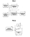
- Fig. 1 is a functional block diagram of an apparatus for estimating a charge rate (SOC) of a secondary cell in a preferred embodiment according to the present invention.
- Fig. 2 is a specific circuit block diagram of the apparatus for estimating the charge rate of the secondary cell in the preferred embodiment according to the present invention.
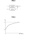
- Fig. 3 is a model view representing an equivalent circuit model of the secondary cell.
- Fig. 4 is a correlation map representing a correlation between an open-circuit voltage and a charge rate (SOC).
- Fig. 5 is an operational flowchart for explaining an operation of a microcomputer of a battery controller of the charge rate estimating apparatus in the first preferred embodiment shown in Fig. 1.
- Figs. 6A, 6B, 6C, 6D, 6E, 6F, 6G, 6H and 6I are characteristic graphs representing results of simulations of current, voltages, and various parameters in a case of the charge rate estimating apparatus in the embodiment shown in Fig. 1
- Fig. 1 shows a functional block diagram of charge rate estimating apparatus in a first preferred embodiment according to the present invention.
- a reference numeral 1 denotes a parameter estimating section based on a cell model with an open-circuit voltage Vo(k) as an offset term.
- a reference numeral 2 denotes a open-circuit voltage calculating section to calculate open-circuit voltage Vo(k)
- a reference numeral 3 denotes a charge rate estimating section that calculate the charge rate from the open-circuit voltage.
- a reference numeral 4 denotes a current I measuring block to detect current I(k) which is charged and discharged into and from the cell
- a reference numeral 5 denotes s terminal voltage of the cell to measure the terminal voltage V(k).
- Fig. 2 shows a block diagram representing a specific structure of the charge rate estimating apparatus in the first embodiment.
- a load such as a motor is driven with the secondary cell and the charge rate estimating apparatus is mounted in a system to charge the secondary cell with a regenerative power of the motor (load).
- Fig. 1 shows a block diagram representing a specific structure of the charge rate estimating apparatus in the first embodiment.
- a load such as a motor is driven with the secondary cell and the charge rate estimating apparatus is mounted in a system to charge the secondary cell with a regenerative power of the motor (load).
- a reference numeral 10 denotes a secondary cell (simply called, a cell)
- a reference numeral 20 denotes a load such as a DC motor
- a reference numeral 30 denotes a battery controller (electronic control unit) to estimate the charge rate (charge state) of the cell having a microcomputer including a ROM (Read Only Memory), a RAM (Random Access Memory), a CPU (central Processing Unit), and Input/Output Interface and other electronic circuits.
- ROM Read Only Memory
- RAM Random Access Memory
- CPU central Processing Unit
- Input/Output Interface and other electronic circuits.
- a reference numeral 40 denotes a current meter to detect a current which is charged into or discharged from the cell
- a reference numeral 50 denotes a voltage meter to detect the terminal voltage of the cell
- a reference numeral 60 denotes a temperature meter to detect a temperature of the cell.
- Battery controller 30 corresponds to parts of parameter estimating section 1, an open-circuit voltage Vo(k) and a charge rate estimating section 3.
- Current meter 40 corresponds to current I(k) measuring section and voltage meter 50 correspond to terminal voltage V(k) measuring section 5.
- Fig. 3 is an equivalent circuit representing an equivalent circuit model of the secondary cell.
- V K •( T 2 • s +1) T 1 • s +1 • I + 1 T 3 • s +1 V 0
- a model input is a current I [A] (a positive value represents a charge and a negative value represents a discharge)
- a model output is a terminal voltage V [V]
- an open-circuit voltage is V 0
- K denotes an internal resistance
- T 1 through T 3 denote time constants (T 1 ⁇ T 2 ⁇ T 3 , T 1 « T 3 )
- s denotes a Laplace transform operator.
- Open-circuit voltage V 0 can be described by an equation (8), supposing that a value of a current I multiplied with a variable efficiency of A is integrated from a certain initial state.
- V 0 A s • I
- equation (9) is resulted.
- V 0 K •( T 2 • s +1) T 1 • s +1 • I + 1 T 3 • s +1 • A s • I
- Equation (9) corresponds to equation (3) A(s), B(s), and C(s) in equation (3), the following equations are substituted into equation (9) in the same way as the case of equation (7).
- a (s) T 1 •s + 1, B(s) - K •(T 2 •s + 1)
- C(s) T 3 •s + 1.
- equation (3) is a generalized equation and this application to a first order model is equation (9). If equation (9) is arranged, an equation of (10) is given.
- equation (4) is the generalized function
- equation (12) is the application of equation (4) to the first order model.
- LPF low pass filter
- BPF band pass filter
- Equation (15) is a product-sum equation of measurable values and unknown parameters.
- a standard (general) type (equation (16)) of the adaptive digital filter is coincident with equation (15). It is noted that ⁇ T means a transposed vector in which a row and column of a vector ⁇ ware mutually exchanged.
- a both-limitation trace gain method is used which improves a logical demerit of a simple " an adaptive digital filter by means of a least square method " such that once the estimated value is converged, an accurate estimation cannot be made any more even if the parameters are changed.
- a parameter estimating algorithm to estimate unknown parameter vector ⁇ with equation (16) as a prerequisite is as shown in an equation (18). It is noted that the parameter estimated value at a time point of k is ⁇ (k).
- ⁇ 1 , ⁇ 3 (k), ⁇ u , and ⁇ L denote initial set value
- b ⁇ ⁇ 1 ⁇ 1, 0 ⁇ ⁇ 3 (k) ⁇ ⁇
- P(0) is a sufficiently large value
- ⁇ (0) provides an initial value which is non-zero but very sufficiently small value
- trace ⁇ P ⁇ means a trace of matrix P.
- Fig. 5 shows an operational flowchart carrying out the microcomputer of battery controller 30.
- a routine shown in 5 is carried out for each constant period of time T 0 .
- I(k) is the present value and I(k -1) means a one previous value of I(k).
- battery controller 30 measures current I(k) and I(k -1) means one previous value of I(k).
- battery controller 30 carries out a turn on-and-off determination of an interrupt relay of the secondary cell. That is to say, battery controller 30 performs the on-and-off control of the interrupt relay of the secondary cell.
- the routine goes to a step S30.
- step S40 the routine goes to a step S40.
- step S30 when the relay is engaged, the routine goes to a step S540.
- step S530 battery controller 30 serves to store terminal voltage V(k) to as an initial value of the terminal voltage V_ini.
- a low pass filtering or band pass filtering are carried out the current I(k) and terminal voltage difference value ⁇ V(k) on the basis of equation (13).
- Io(k) through I 3 (k) and V 1 (k) through V 3 (k) are calculated from equation (19).
- a responsive characteristic of low pass filter G 1 (s) is set to be slow so as to reduce observation noises.
- p 1 recited in equation (19) denotes a constant determined according to the responsive characteristic of G 1 (s).
- I 0 (k) through I 3 (k) calculated at step S50 and V 1 (k) through V 3 (k) are substituted into equation (18).
- Equation (18) the parameter estimation algorithm in the adaptive digital filter, viz., equation (18) is executed to calculate parameter estimated value ⁇ (k).
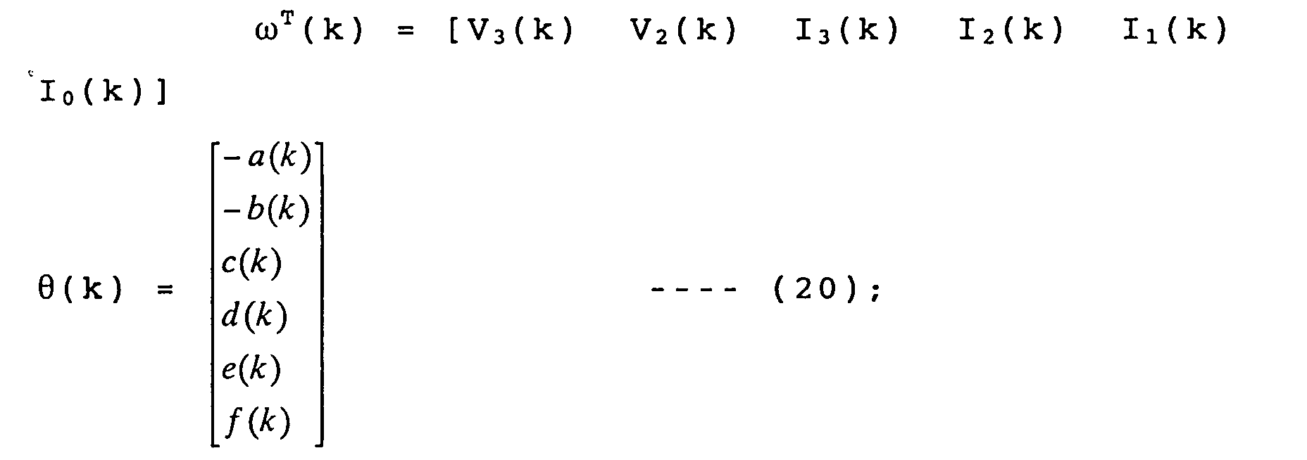
- y(k), ⁇ T (k), and ⁇ (k) are shown in equation (20).
- a through e of parameter estimated value ⁇ (k) calculated at step S60 are substituted into the following equation (22) in which the above-described cell model equation (7) is deformed to calculate V 0 ' which is an alternative to open-circuit voltage V 0 . Since the variation in open-circuit voltage V 0 is smooth, V 0 ' can be used alternatively. It is noted that the derivation herein is a variation ⁇ V 0 (k) of the open-circuit voltage from the estimated calculation start time.
- Equation (21) an equation of [1/C1(s)]I in equation (21) is replaced with an equation (24) corresponds to equation (22). It is also noted that, in the derivation of equation (22), K in equation (21) is strictly different from e in equation (21). However, since, physically, K >> A • T 1 , e is approximated to K (e ⁇ K). Then, each coefficient a through e in equation (22) is the contents shown in equation (23).
- Equation (24) denotes a constant to determine a responsive characteristic of G 2 (s).
- T 1 of the cell parameter is known to be several seconds.
- T' 1 in equation (24) is set to be approximated value to T 1 .
- equation (21) corresponds to equation (5).
- equation (5) is a generalization equation and the application of equation (5) to the first order model is equation (2).
- battery controller 30 adds the open-circuit voltage initial value, i.e., terminal voltage initial value V_ini to a variation ⁇ V 0 (k) of open-circuit voltage V 0 so as to obtain open-circuit voltage estimated value V 0 (k) from the following equation (25).
- V 0 (k) ⁇ V 0 (k) + V_ini
- battery controller 30 stores the necessary numerical values needed in the subsequent calculation and the present routine is ended. As described above, an operation of the apparatus for estimating the charge rate of the secondary cell has been described.
- the estimated open-circuit voltage can be converted to the charge rate. Hence, it is possible to sequentially estimate the charge rate in the same way as the parameters described above.
- equation (1) which is the relationship equation of current I and terminal voltage V of the secondary cell
- equation (4) the equation such that no offset term is included (viz., the open-circuit voltage V 0 ), a product-and-addition equation between a measurable current I which is filter processed and a terminal voltage V which is filter processed and unknown parameter (coefficient parameters of poly-nominal equations A(s), B(s), and C(s) and h) is obtained.
- a normally available adaptive digital filter (the least mean square method and well known parameter estimation algorithm) can directly be applied in a continuous time series.
- the unknown parameters can be estimated in the batch processing manner and the estimated parameter h is substituted into equation (2), the estimated value of open-circuit voltage V 0 can easily be calculated. All of these parameters are varied instantaneously, the adaptive digital filter can serve to estimate the charge rate at any time with a high accuracy. Since a constant relationship between open-circuit voltage Vo and the charge rate SOC is established as shown in Fig. 4, if this relationship is previously stored, the charge rate SOC can be estimated from the estimated value of open-circuit voltage V 0 .
- Figs. 6A through 6I integrally shows signal timing charts with current I and terminal voltage V inputted into adaptive digital filter and representing results of simulation graphs when each parameter is estimated.
- T 1 ⁇ T 0 . Since all parameters a through f (refer to equation (11)) are favorably estimated, the estimated value of open-circuit voltage V 0 can be said to be well coincident with a real value.
- a reason that a right side second term of equation (6) is described is to indicate that the open-circuit voltage estimated value is coincident with a real value almost without delay in spite of the fact that a late term of time constant T 3 is measured on the terminal voltage inputted into the adaptive filter.
- T 3 time constant
Landscapes
- Engineering & Computer Science (AREA)
- Power Engineering (AREA)
- Physics & Mathematics (AREA)
- General Physics & Mathematics (AREA)
- Secondary Cells (AREA)
- Tests Of Electric Status Of Batteries (AREA)
Abstract
Description


Claims (18)
- A charge rate estimating apparatus for a secondary cell (10), comprising:a current detecting section (4) capable of measuring a current flowing through the secondary cell;a terminal voltage detecting section (5) capable of measuring a voltage across terminals of the secondary cell;a parameter estimating section (1, 2) that calculates an adaptive digital filtering using a cell model in a continuous time series shown in an equation (1) and estimates all of parameters at one time, the parameters corresponding to an open-circuit voltage which is an offset term of the equation (1) and coefficients of A(s), B(s), and C(s) which are transient terms; anda charge rate estimating section (3) that estimates the charge rate from a relationship between a previously derived open-circuit voltage V0 and the charge rate SOC using the open-circuit voltage V0,
- A charge rate estimating apparatus for a secondary cell as claimed in claim 1, wherein the open-circuit voltage V0 of the cell model in the continuous time series shown in the equation (1) is approximated by means of an equation (2) to provide an equation (3) and the digital filter calculation is carried out using the equation (3) and equivalent equation (4), h is estimated in at least equation (4), the estimated h is substituted into equation (2) to derive an open-circuit voltage V0, and the charge rate is estimated from a relationship between the previously derived open-circuit voltage V0, and the charge rate is estimated from a relationship between the previously proposed open-circuit voltage V0 and the charge rate (SOC).

- A charge rate estimating apparatus for a secondary cell as claimed in claim 1, wherein the open-circuit voltage V0 of the cell model in the time continuous time series is approximated in an equation (2) to calculate an equation (3), the adaptive digital filter calculation is carried out using an equation (4) which is equivalent to the equation (3), A(s), B(s), and C(s) are estimated from equation (4), the estimated A(s), B(s), and C(s) are substituted into equation (5) to determine V0/G2(s) and the charge rate is estimated from the relationship between the previously derived open-circuit voltage V0 and the charge rate (SOC) using the derived V0/G2(s) in place of the open-circuit voltage V0,

- A charge rate estimating apparatus for a secondary cell as claimed in any one of the preceding claims 1 through 3, wherein the cell model is calculated from an equation (6), .
- A charge rate estimating apparatus for a secondary cell as claimed in claim 4, wherein
- A charge rate estimating apparatus for a secondary cell as claimed in claim 5, wherein
- A charge rate estimating apparatus for a secondary cell as claimed in claim 6, wherein
- A charge rate estimating apparatus for a secondary cell as claimed in claim 7, wherein a stable low pass filter G1(s) is introduced into both sides of the equation (10) to derive the following equation:
- A charge rate estimating apparatus for a Secondary cell as claimed in claim 8, wherein actually measurable currents I and terminal voltages V which are processed by means of a low pass filter are as follows:
- A charge rate estimating apparatus for a secondary cell as claimed in claim 9, wherein, using the equation (13), the equation of (12) is rewritten and rearranged as follows:and the equation (15) corresponds to a general equation which is coincident with a standard form of a general adaptive digital filter of equation (16):


- A charge rate estimating apparatus for a Secondary cell as claimed in claim 10, wherein a parameter estimating algorithm with the equation (16) as a prerequisite is defined as follows:wherein (k) denotes a parameter estimated value at a time point of k (k = 0, 1, 2, 3 ---), λ1, λ3 (k) , γu, and γL denote initial set value, b < λ1 < 1, 0 < λ3(k) < ∞, P(0) is a sufficiently large value, (0) provides an initial value which is non-zero but very sufficiently small value, and trace {P} means a trace of matrix P.

- A charge rate estimating method for a secondary cell, comprising:measuring a current flowing through the secondary cell;measuring a voltage across terminals of the secondary cell;calculating an adaptive digital filtering using a cell model in a continuous time series shown in an equation (1);estimating all of parameters at one time, the parameters corresponding to an open-circuit voltage which is an offset term of the equation (1) and coefficients of A(s), B(s), and C(s) which are transient terms; andestimating the charge rate from a relationship between a previously derived open-circuit voltage V0 and the charge rate SOC using the open-circuit voltage V0,
- A charge rate estimating method for a secondary cell as claimed in claim 12, wherein the open-circuit voltage V0 of the cell model in the continuous time series shown in the equation (1) is approximated by means of an equation (2) to provide an equation (3) and the digital filter calculation is carried out using the equation (3) and equivalent equation (4), h is estimated in at least equation (4), the estimated value of h is substituted into equation (2) to derive an open-circuit voltage V0, and the charge rate is estimated from a relationship between the previously derived open-circuit voltage V0, and the charge rate is estimated from a relationship between the previously proposed open-circuit voltage V0 and the charge rate (SOC).

- A charge rate estimating method for a secondary cell as claimed in claim 12, wherein the open-circuit voltage V0 of the cell model in the continuous time series is approximated in an equation (2) to calculate an equation (3), the adaptive digital filter calculation is carried out using an equation (4) which is equivalent to the equation (3), A(s), B(s), and C(s) are estimated from the equation (4), the estimated A(s), B(s), and C(s) are substituted into equation (5) to determine V0/G2(s) and the charge rate is estimated from the relationship between the previously derived open-circuit voltage V0 and the charge rate (SOC) using the derived V0/G2(s) in place of the open-circuit voltage V0,

- A charge rate estimating method for a secondary cell as claimed in claim 12, wherein the cell model is calculated from an equation (6),
- A charge rate estimating method for a secondary cell, comprising:measuring (30) a current I(k) flowing through the secondary cell;measuring (30) a terminal voltage V(k) across the secondary cell;storing (30) the terminal voltage V(k) when a current is zeroed as an initial value of the terminal voltage ΔV(k) = V(k) - V_ini;determining (30) instantaneous current values I0(k), I1(k), and I3(k) and instantaneous terminal voltages V1(k), V2(k), and V3(k) from an equation (19),substituting (30) the instantaneous current values I0(k), I1(k), and I3(k) and the instantaneous terminal voltages V1(k), V2(k), and V3(k) into an equation (18),wherein (k) denotes a parameter estimated value at a time point of k (k = 0, 1, 2, 3 ---), λ1, λ3(k), γu, and γL denote initial set value, b < λ1 < 1, 0 < λ3(k) < ∞. P(0) is a sufficiently large value, (0) provides an initial value which is non-zero but very sufficiently small value, trace{P} means a trace of matrix P, wherein y(k) = V1(k)

 substituting (30) a, b, c, d, e, and f in the parameter estimated value (k) into and equation (22) to calculate V0' which is an alternate of V0 which corresponds to a variation ΔV0(k) of the open-circuit voltage estimated value from a time at which the estimated calculation start is carried out;calculating (30) an open-circuit voltage estimated value V0(k) according the variation ΔV0(k) of the open-circuit voltage estimated value and the terminal voltage initial value V_ini.
 - A charge rate estimating method for a secondary cell as claimed in claim 16, which further comprises:calculating (30) a charge rate (SOC) from the open-circuit voltage estimated value ΔV0(k).
- A charge rate estimating method for a secondary cell as claimed in claim 17, wherein the charge rate (SOC) is calculated using a correlation map between the open-circuit voltage V0 and the charge rate of the secondary cell from the open-circuit voltage estimated value ΔV0(k).
Applications Claiming Priority (2)
| Application Number | Priority Date | Filing Date | Title |
|---|---|---|---|
| JP2002340803A JP3714321B2 (en) | 2002-11-25 | 2002-11-25 | Secondary battery charge rate estimation device |
| JP2002340803 | 2002-11-25 |
Publications (3)
| Publication Number | Publication Date |
|---|---|
| EP1422804A2 true EP1422804A2 (en) | 2004-05-26 |
| EP1422804A3 EP1422804A3 (en) | 2005-07-27 |
| EP1422804B1 EP1422804B1 (en) | 2007-09-26 |
Family
ID=32212157
Family Applications (1)
| Application Number | Title | Priority Date | Filing Date |
|---|---|---|---|
| EP03026573A Expired - Lifetime EP1422804B1 (en) | 2002-11-25 | 2003-11-18 | State of charge estimating apparatus and method for a secondary cell |
Country Status (5)
| Country | Link |
|---|---|
| US (1) | US7098625B2 (en) |
| EP (1) | EP1422804B1 (en) |
| JP (1) | JP3714321B2 (en) |
| CN (2) | CN2724218Y (en) |
| DE (1) | DE60316526T2 (en) |
Cited By (5)
| Publication number | Priority date | Publication date | Assignee | Title |
|---|---|---|---|---|
| EP2037289A1 (en) * | 2007-09-14 | 2009-03-18 | Calsonic Kansei Corporation | Internal state estimating device of secondary battery |
| EP1901413A3 (en) * | 2006-09-08 | 2012-04-04 | Samsung SDI Co., Ltd. | Battery management system and method |
| EP1975635A3 (en) * | 2007-03-29 | 2012-08-15 | The Furukawa Electric Co., Ltd. | Method and device for estimating battery residual capacity, and battery power supply system |
| EP2107385A4 (en) * | 2007-03-23 | 2014-01-01 | Toyota Motor Co Ltd | DEVICE FOR ESTIMATING THE CONDITION OF A SECONDARY BATTERY |
| CN119812523A (en) * | 2024-12-24 | 2025-04-11 | 深圳市卡莱福科技有限公司 | Automobile emergency starting power supply control system and method |
Families Citing this family (30)
| Publication number | Priority date | Publication date | Assignee | Title |
|---|---|---|---|---|
| JP4547908B2 (en) | 2003-12-25 | 2010-09-22 | 日産自動車株式会社 | Secondary battery input / output possible power estimation device |
| US7554295B2 (en) * | 2004-04-06 | 2009-06-30 | Cobasys, Llc | Determination of IR-free voltage in hybrid vehicle applications |
| US7382110B2 (en) * | 2004-04-23 | 2008-06-03 | Sony Corporation | Method of charging secondary battery, method of calculating remaining capacity rate of secondary battery, and battery pack |
| JP4830382B2 (en) | 2005-07-19 | 2011-12-07 | 日産自動車株式会社 | Secondary battery charge rate estimation device |
| JP4720364B2 (en) * | 2005-08-22 | 2011-07-13 | 日産自動車株式会社 | Secondary battery internal resistance estimation device |
| JP4692246B2 (en) | 2005-11-29 | 2011-06-01 | 日産自動車株式会社 | Secondary battery input / output possible power estimation device |
| KR20090077657A (en) * | 2008-01-11 | 2009-07-15 | 에스케이에너지 주식회사 | Method and device for measuring SOC of battery in battery management system |
| JP5262179B2 (en) * | 2008-02-26 | 2013-08-14 | 日産自動車株式会社 | Secondary battery charging rate estimation device and charging rate estimation method |
| JP5028315B2 (en) * | 2008-03-31 | 2012-09-19 | 川崎重工業株式会社 | Method and apparatus for estimating state of charge of secondary battery |
| KR101187766B1 (en) * | 2008-08-08 | 2012-10-05 | 주식회사 엘지화학 | Apparatus and Method for cell balancing based on battery's voltage variation pattern |
| US8321164B2 (en) * | 2008-09-25 | 2012-11-27 | GM Global Technology Operations LLC | Method and system for determining a state of charge of a battery based on a transient response |
| DE102009000782A1 (en) * | 2008-12-04 | 2010-06-10 | Robert Bosch Gmbh | Method for determining the state of charge of a secondary intercalation cell of a rechargeable battery |
| JP5691592B2 (en) * | 2010-02-18 | 2015-04-01 | 日産自動車株式会社 | Battery state estimation device |
| RU2491566C1 (en) * | 2010-02-18 | 2013-08-27 | Ниссан Мотор Ко., Лтд. | Device for estimation of battery state and method for estimation of battery state |
| JP5520657B2 (en) | 2010-03-30 | 2014-06-11 | 古河電気工業株式会社 | CHARGE RATE ESTIMATION METHOD, CHARGE RATE ESTIMATION DEVICE, AND SECONDARY BATTERY POWER SUPPLY SYSTEM |
| JP5327151B2 (en) * | 2010-07-01 | 2013-10-30 | 株式会社デンソー | Emergency call system |
| JP5400732B2 (en) * | 2010-09-09 | 2014-01-29 | カルソニックカンセイ株式会社 | Parameter estimation device |
| JP5318128B2 (en) * | 2011-01-18 | 2013-10-16 | カルソニックカンセイ株式会社 | Battery charge rate estimation device |
| US20140340045A1 (en) * | 2012-01-26 | 2014-11-20 | Calsonic Kansei Corporation | Apparatus for battery state estimation |
| JP5319854B1 (en) * | 2012-02-22 | 2013-10-16 | カルソニックカンセイ株式会社 | Parameter estimation device |
| JP5803767B2 (en) * | 2012-03-22 | 2015-11-04 | 株式会社デンソー | Secondary battery charge equivalent amount calculation device |
| JP5944291B2 (en) * | 2012-10-05 | 2016-07-05 | カルソニックカンセイ株式会社 | Battery parameter estimation apparatus and method |
| CN103018680B (en) * | 2012-12-11 | 2014-07-16 | 矽力杰半导体技术(杭州)有限公司 | Metering method and metering device of battery level and battery supply set |
| CN103077291B (en) * | 2013-01-25 | 2016-05-18 | 华北电力大学 | The battery charge and discharge process digital simulation method of initial state-of-charge can be set |
| CN103078334A (en) * | 2013-02-04 | 2013-05-01 | 中冶南方工程技术有限公司 | Method for directly identifying continuous time model of thyristor control reactor (TCR)-type reactive compensation device |
| US9377512B2 (en) * | 2013-05-08 | 2016-06-28 | GM Global Technology Operations LLC | Battery state estimator combining electrochemical solid-state concentration model with empirical equivalent-circuit model |
| KR101653967B1 (en) * | 2014-09-23 | 2016-09-07 | 주식회사 실리콘마이터스 | Apparatus and method for measuring battery residual quantity |
| FR3029296B1 (en) * | 2014-11-28 | 2016-12-30 | Renault Sa | AUTOMATIC METHOD OF ESTIMATING THE CHARGING STATE OF A CELL OF A BATTERY |
| ES2998808T3 (en) * | 2020-08-03 | 2025-02-21 | Lg Energy Solution Ltd | Battery diagnosis device, battery pack, battery system, and battery diagnosis method |
| CN113092902A (en) * | 2021-03-29 | 2021-07-09 | 一汽奔腾轿车有限公司 | Automobile wireless charging electromagnetic compatibility test system and control method thereof |
Family Cites Families (11)
| Publication number | Priority date | Publication date | Assignee | Title |
|---|---|---|---|---|
| DE3811371A1 (en) * | 1988-04-05 | 1989-10-19 | Habra Elektronik | METHOD FOR CHARGING AND SIMULTANEOUSLY CHECKING THE CONDITION OF A NICKELCADMIUM BATTERY |
| US5321627A (en) * | 1992-03-11 | 1994-06-14 | Globe-Union, Inc. | Battery monitor and method for providing operating parameters |
| US6331762B1 (en) * | 1997-11-03 | 2001-12-18 | Midtronics, Inc. | Energy management system for automotive vehicle |
| AUPP110497A0 (en) * | 1997-12-23 | 1998-01-22 | Telstra Corporation Limited | Electrical parameter monitoring system |
| KR100317598B1 (en) | 1999-03-13 | 2001-12-22 | 박찬구 | A Laplace transform impedance spectrometer |
| JP3752879B2 (en) | 1999-03-18 | 2006-03-08 | 株式会社豊田中央研究所 | Rechargeable battery remaining capacity estimation method |
| JP3752888B2 (en) | 1999-05-11 | 2006-03-08 | トヨタ自動車株式会社 | Battery state detection device |
| DE10126891A1 (en) * | 2001-06-01 | 2002-12-05 | Vb Autobatterie Gmbh | Predicting electrochemical element load capacity involves correcting equivalent circuit input voltage w.r.t measured voltage using function with logarithmic current dependency as nonlinear term |
| JP3747826B2 (en) | 2001-09-05 | 2006-02-22 | 日産自動車株式会社 | Secondary battery charge rate estimation device |
| US6850038B2 (en) * | 2002-05-14 | 2005-02-01 | Yazaki Corporation | Method of estimating state of charge and open circuit voltage of battery, and method and device for computing degradation degree of battery |
| US6927554B2 (en) * | 2003-08-28 | 2005-08-09 | General Motors Corporation | Simple optimal estimator for PbA state of charge |
-
2002
- 2002-11-25 JP JP2002340803A patent/JP3714321B2/en not_active Expired - Fee Related
-
2003
- 2003-10-30 US US10/695,800 patent/US7098625B2/en not_active Expired - Fee Related
- 2003-11-18 DE DE60316526T patent/DE60316526T2/en not_active Expired - Fee Related
- 2003-11-18 EP EP03026573A patent/EP1422804B1/en not_active Expired - Lifetime
- 2003-11-25 CN CN200320116788XU patent/CN2724218Y/en not_active Expired - Fee Related
- 2003-11-25 CN CNB2003101183590A patent/CN1322627C/en not_active Expired - Fee Related
Cited By (5)
| Publication number | Priority date | Publication date | Assignee | Title |
|---|---|---|---|---|
| EP1901413A3 (en) * | 2006-09-08 | 2012-04-04 | Samsung SDI Co., Ltd. | Battery management system and method |
| EP2107385A4 (en) * | 2007-03-23 | 2014-01-01 | Toyota Motor Co Ltd | DEVICE FOR ESTIMATING THE CONDITION OF A SECONDARY BATTERY |
| EP1975635A3 (en) * | 2007-03-29 | 2012-08-15 | The Furukawa Electric Co., Ltd. | Method and device for estimating battery residual capacity, and battery power supply system |
| EP2037289A1 (en) * | 2007-09-14 | 2009-03-18 | Calsonic Kansei Corporation | Internal state estimating device of secondary battery |
| CN119812523A (en) * | 2024-12-24 | 2025-04-11 | 深圳市卡莱福科技有限公司 | Automobile emergency starting power supply control system and method |
Also Published As
| Publication number | Publication date |
|---|---|
| JP3714321B2 (en) | 2005-11-09 |
| US7098625B2 (en) | 2006-08-29 |
| EP1422804A3 (en) | 2005-07-27 |
| DE60316526D1 (en) | 2007-11-08 |
| CN2724218Y (en) | 2005-09-07 |
| CN1322627C (en) | 2007-06-20 |
| JP2004178848A (en) | 2004-06-24 |
| EP1422804B1 (en) | 2007-09-26 |
| DE60316526T2 (en) | 2008-01-31 |
| CN1503399A (en) | 2004-06-09 |
| US20040100227A1 (en) | 2004-05-27 |
Similar Documents
| Publication | Publication Date | Title |
|---|---|---|
| EP1422804A2 (en) | Apparatus and method for estimating charge rate of secondary cell | |
| JP3714333B2 (en) | Secondary battery input / output possible power estimation device | |
| CN100529787C (en) | Device and method for estimating the inputtable/outputtable power of a secondary battery | |
| US7714736B2 (en) | Adaptive filter algorithm for estimating battery state-of-age | |
| JP4830382B2 (en) | Secondary battery charge rate estimation device | |
| EP1688754B1 (en) | Battery management apparatus | |
| US6534954B1 (en) | Method and apparatus for a battery state of charge estimator | |
| EP1555537B1 (en) | Battery remaining capacity measuring apparatus | |
| JP5442583B2 (en) | State detection device for power supply and power supply device | |
| KR101439798B1 (en) | Battery state estimating apparatus and battery state estimating method | |
| CN108701872A (en) | battery management system, battery system and hybrid vehicle control system | |
| JPWO1999061929A1 (en) | Battery charge state estimation means and battery degradation state estimation method | |
| KR20010043872A (en) | Means for estimating charged state of battery and method for estimating degraded state of battery | |
| US20110213576A1 (en) | Method for calculating the charge state of a battery | |
| JP2010217079A (en) | Device for estimation of total capacity of secondary battery | |
| JP3714314B2 (en) | Secondary battery charge rate estimation device | |
| JP2003075517A (en) | Battery recharge rate estimation device | |
| JP3852372B2 (en) | Secondary battery charge rate estimation device | |
| JP4103569B2 (en) | Secondary battery charge rate estimation device | |
| JP2004245627A (en) | Battery recharge rate estimation device | |
| JP3852371B2 (en) | Secondary battery charge rate estimation device | |
| CN115877220A (en) | A battery SOF calculation method, a battery management system, and an electrical device | |
| JP3714284B2 (en) | Secondary battery charge rate estimation device | |
| JP4666149B2 (en) | Secondary battery input / output possible power estimation device | |
| JP2007003438A (en) | Secondary battery charge rate estimation device |
Legal Events
| Date | Code | Title | Description |
|---|---|---|---|
| PUAI | Public reference made under article 153(3) epc to a published international application that has entered the european phase |
Free format text: ORIGINAL CODE: 0009012 |
|
| 17P | Request for examination filed |
Effective date: 20031118 |
|
| AK | Designated contracting states |
Kind code of ref document: A2 Designated state(s): AT BE BG CH CY CZ DE DK EE ES FI FR GB GR HU IE IT LI LU MC NL PT RO SE SI SK TR |
|
| AX | Request for extension of the european patent |
Extension state: AL LT LV MK |
|
| PUAL | Search report despatched |
Free format text: ORIGINAL CODE: 0009013 |
|
| AK | Designated contracting states |
Kind code of ref document: A3 Designated state(s): AT BE BG CH CY CZ DE DK EE ES FI FR GB GR HU IE IT LI LU MC NL PT RO SE SI SK TR |
|
| AX | Request for extension of the european patent |
Extension state: AL LT LV MK |
|
| RIC1 | Information provided on ipc code assigned before grant |
Ipc: 7G 01R 31/36 A |
|
| AKX | Designation fees paid |
Designated state(s): DE FR GB |
|
| 17Q | First examination report despatched |
Effective date: 20060118 |
|
| GRAP | Despatch of communication of intention to grant a patent |
Free format text: ORIGINAL CODE: EPIDOSNIGR1 |
|
| RTI1 | Title (correction) |
Free format text: CHARGE RATE ESTIMATING APPARATUS AND METHOD FOR A SECONDARY CELL |
|
| RTI1 | Title (correction) |
Free format text: STATE OF CHARGE ESTIMATING APPARATUS AND METHOD FOR A SECONDARY CELL |
|
| GRAS | Grant fee paid |
Free format text: ORIGINAL CODE: EPIDOSNIGR3 |
|
| GRAA | (expected) grant |
Free format text: ORIGINAL CODE: 0009210 |
|
| AK | Designated contracting states |
Kind code of ref document: B1 Designated state(s): DE FR GB |
|
| REG | Reference to a national code |
Ref country code: GB Ref legal event code: FG4D |
|
| REF | Corresponds to: |
Ref document number: 60316526 Country of ref document: DE Date of ref document: 20071108 Kind code of ref document: P |
|
| PGFP | Annual fee paid to national office [announced via postgrant information from national office to epo] |
Ref country code: DE Payment date: 20071206 Year of fee payment: 5 |
|
| ET | Fr: translation filed | ||
| PGFP | Annual fee paid to national office [announced via postgrant information from national office to epo] |
Ref country code: GB Payment date: 20071114 Year of fee payment: 5 Ref country code: FR Payment date: 20071108 Year of fee payment: 5 |
|
| PLBE | No opposition filed within time limit |
Free format text: ORIGINAL CODE: 0009261 |
|
| STAA | Information on the status of an ep patent application or granted ep patent |
Free format text: STATUS: NO OPPOSITION FILED WITHIN TIME LIMIT |
|
| 26N | No opposition filed |
Effective date: 20080627 |
|
| GBPC | Gb: european patent ceased through non-payment of renewal fee |
Effective date: 20081118 |
|
| REG | Reference to a national code |
Ref country code: FR Ref legal event code: ST Effective date: 20090731 |
|
| PG25 | Lapsed in a contracting state [announced via postgrant information from national office to epo] |
Ref country code: DE Free format text: LAPSE BECAUSE OF NON-PAYMENT OF DUE FEES Effective date: 20090603 |
|
| PG25 | Lapsed in a contracting state [announced via postgrant information from national office to epo] |
Ref country code: GB Free format text: LAPSE BECAUSE OF NON-PAYMENT OF DUE FEES Effective date: 20081118 |
|
| PG25 | Lapsed in a contracting state [announced via postgrant information from national office to epo] |
Ref country code: FR Free format text: LAPSE BECAUSE OF NON-PAYMENT OF DUE FEES Effective date: 20081130 |