EP1422780A1 - Polymer battery and related method - Google Patents
Polymer battery and related method Download PDFInfo
- Publication number
- EP1422780A1 EP1422780A1 EP03020614A EP03020614A EP1422780A1 EP 1422780 A1 EP1422780 A1 EP 1422780A1 EP 03020614 A EP03020614 A EP 03020614A EP 03020614 A EP03020614 A EP 03020614A EP 1422780 A1 EP1422780 A1 EP 1422780A1
- Authority
- EP
- European Patent Office
- Prior art keywords
- active material
- electrode active
- material layer
- polymer
- positive electrode
- Prior art date
- Legal status (The legal status is an assumption and is not a legal conclusion. Google has not performed a legal analysis and makes no representation as to the accuracy of the status listed.)
- Granted
Links
Images


Classifications
-
- H—ELECTRICITY
- H01—ELECTRIC ELEMENTS
- H01M—PROCESSES OR MEANS, e.g. BATTERIES, FOR THE DIRECT CONVERSION OF CHEMICAL ENERGY INTO ELECTRICAL ENERGY
- H01M10/00—Secondary cells; Manufacture thereof
- H01M10/05—Accumulators with non-aqueous electrolyte
- H01M10/056—Accumulators with non-aqueous electrolyte characterised by the materials used as electrolytes, e.g. mixed inorganic/organic electrolytes
- H01M10/0564—Accumulators with non-aqueous electrolyte characterised by the materials used as electrolytes, e.g. mixed inorganic/organic electrolytes the electrolyte being constituted of organic materials only
- H01M10/0565—Polymeric materials, e.g. gel-type or solid-type
-
- H—ELECTRICITY
- H01—ELECTRIC ELEMENTS
- H01M—PROCESSES OR MEANS, e.g. BATTERIES, FOR THE DIRECT CONVERSION OF CHEMICAL ENERGY INTO ELECTRICAL ENERGY
- H01M10/00—Secondary cells; Manufacture thereof
- H01M10/04—Construction or manufacture in general
- H01M10/0436—Small-sized flat cells or batteries for portable equipment
-
- H—ELECTRICITY
- H01—ELECTRIC ELEMENTS
- H01M—PROCESSES OR MEANS, e.g. BATTERIES, FOR THE DIRECT CONVERSION OF CHEMICAL ENERGY INTO ELECTRICAL ENERGY
- H01M10/00—Secondary cells; Manufacture thereof
- H01M10/05—Accumulators with non-aqueous electrolyte
- H01M10/052—Li-accumulators
- H01M10/0525—Rocking-chair batteries, i.e. batteries with lithium insertion or intercalation in both electrodes; Lithium-ion batteries
-
- H—ELECTRICITY
- H01—ELECTRIC ELEMENTS
- H01M—PROCESSES OR MEANS, e.g. BATTERIES, FOR THE DIRECT CONVERSION OF CHEMICAL ENERGY INTO ELECTRICAL ENERGY
- H01M4/00—Electrodes
- H01M4/02—Electrodes composed of, or comprising, active material
- H01M4/36—Selection of substances as active materials, active masses, active liquids
- H01M4/60—Selection of substances as active materials, active masses, active liquids of organic compounds
-
- H—ELECTRICITY
- H01—ELECTRIC ELEMENTS
- H01M—PROCESSES OR MEANS, e.g. BATTERIES, FOR THE DIRECT CONVERSION OF CHEMICAL ENERGY INTO ELECTRICAL ENERGY
- H01M50/00—Constructional details or processes of manufacture of the non-active parts of electrochemical cells other than fuel cells, e.g. hybrid cells
- H01M50/40—Separators; Membranes; Diaphragms; Spacing elements inside cells
- H01M50/409—Separators, membranes or diaphragms characterised by the material
- H01M50/411—Organic material
- H01M50/414—Synthetic resins, e.g. thermoplastics or thermosetting resins
- H01M50/417—Polyolefins
-
- H—ELECTRICITY
- H01—ELECTRIC ELEMENTS
- H01M—PROCESSES OR MEANS, e.g. BATTERIES, FOR THE DIRECT CONVERSION OF CHEMICAL ENERGY INTO ELECTRICAL ENERGY
- H01M50/00—Constructional details or processes of manufacture of the non-active parts of electrochemical cells other than fuel cells, e.g. hybrid cells
- H01M50/40—Separators; Membranes; Diaphragms; Spacing elements inside cells
- H01M50/409—Separators, membranes or diaphragms characterised by the material
- H01M50/411—Organic material
- H01M50/414—Synthetic resins, e.g. thermoplastics or thermosetting resins
- H01M50/423—Polyamide resins
-
- H—ELECTRICITY
- H01—ELECTRIC ELEMENTS
- H01M—PROCESSES OR MEANS, e.g. BATTERIES, FOR THE DIRECT CONVERSION OF CHEMICAL ENERGY INTO ELECTRICAL ENERGY
- H01M50/00—Constructional details or processes of manufacture of the non-active parts of electrochemical cells other than fuel cells, e.g. hybrid cells
- H01M50/40—Separators; Membranes; Diaphragms; Spacing elements inside cells
- H01M50/409—Separators, membranes or diaphragms characterised by the material
- H01M50/44—Fibrous material
-
- H—ELECTRICITY
- H01—ELECTRIC ELEMENTS
- H01M—PROCESSES OR MEANS, e.g. BATTERIES, FOR THE DIRECT CONVERSION OF CHEMICAL ENERGY INTO ELECTRICAL ENERGY
- H01M6/00—Primary cells; Manufacture thereof
- H01M6/40—Printed batteries, e.g. thin film batteries
-
- Y—GENERAL TAGGING OF NEW TECHNOLOGICAL DEVELOPMENTS; GENERAL TAGGING OF CROSS-SECTIONAL TECHNOLOGIES SPANNING OVER SEVERAL SECTIONS OF THE IPC; TECHNICAL SUBJECTS COVERED BY FORMER USPC CROSS-REFERENCE ART COLLECTIONS [XRACs] AND DIGESTS
- Y02—TECHNOLOGIES OR APPLICATIONS FOR MITIGATION OR ADAPTATION AGAINST CLIMATE CHANGE
- Y02E—REDUCTION OF GREENHOUSE GAS [GHG] EMISSIONS, RELATED TO ENERGY GENERATION, TRANSMISSION OR DISTRIBUTION
- Y02E60/00—Enabling technologies; Technologies with a potential or indirect contribution to GHG emissions mitigation
- Y02E60/10—Energy storage using batteries
-
- Y—GENERAL TAGGING OF NEW TECHNOLOGICAL DEVELOPMENTS; GENERAL TAGGING OF CROSS-SECTIONAL TECHNOLOGIES SPANNING OVER SEVERAL SECTIONS OF THE IPC; TECHNICAL SUBJECTS COVERED BY FORMER USPC CROSS-REFERENCE ART COLLECTIONS [XRACs] AND DIGESTS
- Y02—TECHNOLOGIES OR APPLICATIONS FOR MITIGATION OR ADAPTATION AGAINST CLIMATE CHANGE
- Y02P—CLIMATE CHANGE MITIGATION TECHNOLOGIES IN THE PRODUCTION OR PROCESSING OF GOODS
- Y02P70/00—Climate change mitigation technologies in the production process for final industrial or consumer products
- Y02P70/50—Manufacturing or production processes characterised by the final manufactured product
-
- Y—GENERAL TAGGING OF NEW TECHNOLOGICAL DEVELOPMENTS; GENERAL TAGGING OF CROSS-SECTIONAL TECHNOLOGIES SPANNING OVER SEVERAL SECTIONS OF THE IPC; TECHNICAL SUBJECTS COVERED BY FORMER USPC CROSS-REFERENCE ART COLLECTIONS [XRACs] AND DIGESTS
- Y10—TECHNICAL SUBJECTS COVERED BY FORMER USPC
- Y10T—TECHNICAL SUBJECTS COVERED BY FORMER US CLASSIFICATION
- Y10T29/00—Metal working
- Y10T29/49—Method of mechanical manufacture
- Y10T29/49002—Electrical device making
- Y10T29/49108—Electric battery cell making
Definitions
- the present invention relates to a polymer battery and its related method and, more particularly, to a polymer battery, which is provided with a positive electrode active material layer and a negative electrode active material layer with a polymer electrolyte layer intervening between such active material layers, and its related method.
- the electrolyte layer needs to have a thin thickness as thinner as possible to shorten a distance through which ion transfers for thereby decreasing internal resistance of the electrolyte layer.
- electrolyte takes the form of semi-solid or solid configuration with low ion conductivity, it is considered that the electrolyte layer needs to be formed in a further thin film configuration.
- Japanese Patent Application Laid-Open Publication No. H10-144349 proposes a structure in which polymer electrolyte includes inorganic solid electrolyte so as to improve a mechanical strength of a polymer electrolyte layer.
- the structure in which the polymer electrolyte layer includes inorganic solid electrolyte to improve the mechanical strength of the polymer solid electrolyte layer has a limited ability to improve the mechanical strength of the polymer solid electrolyte layer and, so, it is considered that when applying the battery incorporating such polymer electrolyte into a device, such as a vehicle, which suffers from vibrations, the room is still left for improvement.
- the present invention has been completed through the studies conducted by the present inventors set forth above and has an object to provide a polymer battery and its related method wherein a thickness of a polymer electrolyte layer is thinned while providing an increased mechanical strength.
- a polymer battery comprises: a positive electrode active material layer; a negative electrode active material layer placed in opposition to the positive electrode active material layer; a polymer electrolyte layer disposed between the positive electrode active material layer and the negative electrode active material layer; and a distance defining member included in the polymer electrolyte layer to define a distance between the positive electrode active material layer and the negative electrode active material layer.
- a polymer battery comprises: a positive electrode active material layer; a negative electrode active material layer placed in opposition to the positive electrode active material layer; a polymer electrolyte layer disposed between the positive electrode active material layer and the negative electrode active material layer; and defining means, included in the polymer electrolyte layer, for defining a distance between the positive electrode active material layer and the negative electrode active material layer.
- a method of manufacturing a polymer battery comprising: forming a polymer electrolyte layer, including a distance defining member, onto one of a positive electrode active material layer and a negative electrode active material layer; and forming the other one of the positive electrode active material layer and the negative electrode active material layer onto the polymer electrolyte layer such that a distance between the positive electrode active material layer and the negative electrode active material layer is defined by the distance defining member.
- the polymer battery of this embodiment is comprised of a positive electrode active material layer and a negative electrode active material layer with a polymer electrolyte layer intervening between the positive electrode active material layer and the negative electrode active material layer and, particularly, has a structure wherein the polymer electrolyte layer includes distance defining members that define a distance between the positive electrode active material layer and the negative electrode active material layer.
- the presently filed embodiment is described below in conjunction with an exemplary case wherein the polymer battery takes the form of a bipolar lithium ion secondary battery (hereinafter merely termed a bipolar battery).
- Fig. 1 is a cross sectional view illustrating the bipolar electrode of the bipolar battery of the presently filed embodiment
- Fig. 2 is a cross sectional view illustrating a structure in which the bipolar electrodes are stacked with electrolyte layers being interposed.
- the bipolar electrode 10 of a sheet shape forming the bipolar battery has a structure wherein a current collector 1 has one surface on which the positive electrode active material layer 2 is disposed and the other surface on which the negative electrode active material layer 3 is disposed, with these component elements being laminated in a unitary configuration.
- the bipolar electrode 10 has a structure in which the positive electrode active material layer 2, the current collector 1 and the negative electrode active material layer 3 are laminated in this order and constitutes a fundamental battery element that forms the bipolar battery.
- the bipolar electrodes 10 with such structures are disposed, such that all the orders to be stacked are identical as shown in Fig. 2, and are sequentially stacked with the polymer electrolyte layers 4 being interposed to form the bipolar battery.
- the reason why the polymer electrolyte layer 4 is interposed between the positive electrode active material layer 2 and the negative electrode active material layer 3 resides in that smooth ion transfer is achieved with an improved power output of the bipolar battery as a whole. Further, since the polymer electrolyte layer 4 is a solid layer, no liquid leakage of electrolyte takes place and no structure to prevent electrolyte from dissolving is required, enabling the bipolar battery to be simplified in structure.
- a stacked body composed of a pair of current collectors 1, 1, and the negative electrode active material layer 3, the electrolyte layer 4 and the positive electrode active material layer 2, which are interposed between the current collectors 1, 1 in a laminated configuration, is termed as a unit cell layer 20.
- Each current collector 1 of the unit cell layer 20 is functionally shared in common with the current collector 1 of an adjacent unit cell layer 20.
- the polymer electrolyte layer 4 is arranged to incorporate the distance defining members whose detail are described below.
- Fig. 3 is a cross sectional view illustrating a structure of the bipolar battery of the presently filed embodiment. Also, in the figure, the number of pieces of the bipolar electrodes 10 is merely illustratively indicated and is not intended to be limited.
- the bipolar electrodes 10 and the electrolyte layers 4 are alternately and sequentially stacked in a stack direction Z, thereby forming a bipolar battery 30 into a stacked body.
- the outermost bipolar electrodes 10, 10 need to have a current collector, serving as a terminal that functions as a positive electrode of the bipolar battery 30, and a current collector, serving a terminal that functions as a negative electrode of the bipolar battery 30, and, in the figure, one which forms the terminal serving as the positive electrode is indicated as a current collector 1a while the other one which forms the terminal serving as the negative electrode is indicated as a current collector 1b.
- an outside surface of the current collector 1a serving as the positive electrode has no need to be formed with the negative electrode active material layer 3 that is consequently dispensed with
- an outside surface of the current collector 1b serving as the negative electrode has no need to be formed with the positive electrode active material layer 2 that is consequently dispensed with. That is, although the positive electrode active material layer 2 and the negative electrode active material layer 3 are shown to be omitted from the outermost electrodes 10a, 10b, if circumstances require, it is not objectionable to take the form of a structure provided with such active material layers but not for use in actual.
- the bipolar battery 30 are fabricated by, firstly, preparing the electrode 10b, having the current collector 1b serving as the negative electrode, the respective electrolyte layers 4, the respective bipolar electrodes 10 and the electrode 10a having the current collector 1a serving as the positive electrode, then, onto the negative electrode active material layer 3 of the electrode 10b, stacking the electrolyte layer 4, the bipolar electrode 10 with the positive electrode active material layer 2 opposing to the electrolyte layer 4, the electrolyte 4 and the bipolar electrode 10 with the negative electrode active material layer 3 opposing to the electrolyte layer 4 in a sequential order to form a stacked structure, and then, stacking the electrode 10a onto such a stacked structure so as to allow the positive electrode active material layer 2 to be opposed thereto for thereby forming a stack body of the battery element, and finally, hermetically sealing the stacked body with laminate sheets 5a and 5b.
- the respective layers to be laminated on the electrode 10b in a sequential order.
- the current collectors 1a and 1b involved in the outermost electrodes 10a, 10b extend to the outside of the bipolar battery 30 to be taken out and serve as a positive terminal and a negative terminal, respectively.
- the battery element such as the bipolar electrode 10 and the electrolyte layer 4 are hermetically sealed under reduced pressure with the laminate sheets 5a and 5b which are bonded at extended portions of the current collectors 1a and 1b.
- the laminate sheets 5a and 5b are made from polymer-metal composite films each of which is formed of a thermally bonding resin film, a metallic foil and a resin film with a rigidity which are laminated in this order, and the thermally bonding resin films of the respective sheets are placed to be opposed to one another and then bonded to one another. Also, due to a probability of short-circuiting to occur in the presence of direct contact between the metallic foils of the laminate sheets 5a, 5b and the current collectors 1a, 1b serving as the terminals, sealing resin may be preferably used for bonding to keep these components in a non-contact capability. As such sealing resin, epoxy resin may be utilized.
- Fig. 4A is a plan view of the polymer electrolyte layer including the distance defining members for the bipolar battery of the presently filed embodiment
- Fig. 4B is a cross section, taken along line IV-IV of Fig. 4A, of the polymer electrolyte layer including such distance defining members.
- the polymer electrolyte layer 4 is comprised of a polymer electrolyte 42 in which the distance defining members 45 are embedded.
- the distance defining members 45 are structured such that a plurality of wire-like members are disposed in parallel to one another in a substantially equally spaced relationship with a given distance.
- the polymer electrolyte layer 4 has a structure that includes the distance defining members 45 by which a distance D is defined between the positive electrode active material layer 2, to be laminated above the polymer electrolyte layer 4, and the negative electrode active material layer 3 to be laminated beneath the polymer electrolyte layer 4.
- the distance defining members 45 define a thickness D along the stack direction Z of the polymer electrolyte layer 4 that is placed between the positive electrode active material layer 2 and the negative electrode active material layer 3.
- Materials to be used for the distance defining members 45 includes resin fibers or metallic thin wires with their surfaces coated with resin. Also, Fig. 4C shows a cross sectional view of one distance defining member 45 formed in an exemplary structure in which a metallic thin wire 45a has a surface coated with a resin layer 45b.
- the polymer electrolyte layer 4 is formed of a solid or semi-solid layer that is made from polymer with ion conductivity and no limitation is intended for material of electrolyte per se provided that it provides the ion conductivity.
- Solid electrolyte includes polymer solid electrolyte such as polyethylene oxide (PEO), polypropylene oxide (PPO) and co-polymer of these materials. Contained in polymer solid electrolyte is supporting salt (lithium salt) for ensuring the ion conductivity.
- supporting salt use may be made of LiBF 4 , LiPF 6 , LiN(SO 2 CF 3 ) 2 , LiN(SO 2 C 2 F 5 ) 2 , Li(C 2 F 5 SO 2 ) 2 N or a mixture of these compounds.
- supporting salt is not limited to these compounds.
- Polyalkylene oxide series polymer such as PEO, PPO is able to dissolve lithium salts such as LiBF 4 , LiPF 6 , LiN(SO 2 CF 3 ) 2 , LiN(SO 2 C 2 F 5 ) 2 , Li(C 2 F 5 SO 2 ) 2 N.
- formation of a bridge structure allows an excellent mechanical strength to be exhibited.
- polymer solid electrolyte may be included in the polymer solid electrolyte layer, the positive electrode active material layer and the negative electrode active material layer, identical polymer solid electrolyte may be used or different polymer solid electrolyte for each layer may be used.
- resin fibers include polypropylene (PP), polyethylene (PE), polyethylene terephthalate (PET), polyamide synthetic fiber (nylon), polyimide and silicone, and same materials may be used for resin to be coated over the metallic thin wire.
- PP polypropylene
- PE polyethylene
- PET polyethylene terephthalate
- Nylon polyamide synthetic fiber
- silicone silicone
- the polymer electrolyte layer 4 may preferably have a thickness equal to or less than 50 ⁇ m.
- the polymer solid electrolyte layer 4 with such distance defining members 45 being disposed in such an embedded state is fabricated in a process discussed below.
- a plurality of PET fibers 45 with a wire diameter of 20 ⁇ m are placed onto a PET film 42a and, then, a mixture of polymer (co-polymer of PEO and PPO), supporting salt (LiN(SO 2 C 2 F 5 ) 2 ) and ultraviolet polymerization initiator (benzyldimethyl-ketal) is coated over the resulting PET film. And, further superposed on the PET film thus coated is another PET film 42b, with polymerization being achieved through ultraviolet radiation to form the polymer electrolyte layer 4.
- a mixture of polymer co-polymer of PEO and PPO
- supporting salt LiN(SO 2 C 2 F 5 ) 2
- ultraviolet polymerization initiator benzyldimethyl-ketal
- the polymer electrolyte layer 4 is formed in a structure with the specified portions thereof being formed of the distance defining members 45 but the other major portion thereof being formed of the polymer electrolyte 42 to enable favorable ion transfer.
- the PET films 42a, 42b are conceptually shown, in actual practice, a boundary between the PET films 42a, 42b substantially disappears upon formation of the polymer electrolyte layer 4.
- the current collector 1 has surface material formed of aluminum.
- the presence of surface material made from aluminum provides an active material layer with a high mechanical strength even if resulting active material layer includes polymer solid electrolyte. That is, no limitation is particularly intended for a structure of the current collector 1 provided that surface material includes aluminum.
- the current collector 1 per se may be formed of aluminum or may take the form of a structure wherein the surface of the current collector 1 is coated with aluminum. That is, the current collector may be of a structure wherein the surface made of other material (such as copper, titanium, nickel, SUS or an alloy of these elements) than aluminum is coated with aluminum. If circumstances demand, the current collector may take the form of a structure in which more than two sheets of plates are laminated.
- the current collector 1 is preferable for the current collector 1 to be made of an aluminum-foil unit body. Although no particular limitation is intended for a thickness of the current collector 1, normally, the thickness lies in a range of approximately 10 to 100 ⁇ m.
- the current collectors 1a, 1b serving as the terminals may not differ from the other current collectors 1 and may be formed of materials set forth above.
- the positive electrode material layer 2 includes positive electrode active material and may include not only positive electrode active material but also polymer solid electrolyte described above.
- supporting salt lithium salt
- conductivity promoting additive agent providing increased electron conductivity
- NMP N-methyl-2-pyrolidone
- AIBN azobisisobutyronitrile
- composite oxides that include lithium and transition metals and may be used in a lithium ion battery of solvent series.
- these include Li • Co series composite compounds such as LiCoO 2 , Li • Ni series composite compounds such as LiNiO 2 , Li • Mn series composite compounds such as spinel LiMn 2 O 4 , and Li • Fe series composite compounds such as LiFeO 2 .
- lithium-transition metal composite oxides as positive electrode active material enables a reaction capability and a cycle durability of the polymer battery to be improved, enabling low cost.
- positive electrode active material may be used with a grain diameter less than that of positive electrode active material generally used in a lithium ion battery of a solvent type in which electrolyte is no solid electrolyte.
- an average grain diameter of positive electrode active material may lie in a range of approximately 0.1 to 5 ⁇ m.
- LiBF 4 LiPF 6 , LiN(SO 2 CF 3 ) 2 , LiN(SO 2 C 2 F 5 ) 2 , Li(C 2 F 5 SO 2 ) 2 N or a mixture of these compounds may be used.
- acetylene black carbon black and graphite may be used as conductivity promoting additive agent.
- the amount of positive electrode active material, polymer solid electrolyte, lithium salt and conductivity promoting additive agent to be blended in the positive electrode active material layer 2 should be determined on consideration of purposes (with a serious view of an output and an energy) of use of the battery and the ion conductivity.
- the smaller the amount of polymer solid electrolyte to be blended in an active material layer the larger will be ion conductive resistance and ion dispersion resistance in the active material layer, resulting degradation in a battery performance.
- the amount of polymer solid electrolyte to be blended in the active material layer increases, deterioration in an energy density of the battery results in.
- the amount of polymer solid electrolyte is determined so as to satisfy an intended purpose.
- the bipolar battery is manufactured with a priority given to a battery reacting capability through the use of polymer solid electrolyte (with ion conductivity: 10 -5 to 10 -4 S/cm) at a current status level.
- polymer solid electrolyte with ion conductivity: 10 -5 to 10 -4 S/cm
- attempts are undertaken to include an increased amount of conductivity promoting additive agent or to decrease a bulk density of active material to allow electron conductive resistance between active material granules to be kept at a low level.
- pore portions are increased to allow these pore portions to be filled with polymer solid electrolyte. Upon conduction of such treatment, the proportion of polymer solid electrolyte may be increased.
- the thickness of the positive electrode material layer 2 and, as set forth above with reference to the amount of materials to be blended, the thickness of the positive electrode material layer 2 should be determined on consideration of purposes (with a serious view of an output and an energy) of use of the battery and the ion conductivity.
- the thickness of the positive electrode material layer 2 lies in a range of approximately 5 to 500 ⁇ m.
- the negative electrode active material layer 3 includes negative electrode active material and, in addition to this material, may include polymer solid electrolyte.
- supporting salt lithium salt
- conductivity promoting additive agent providing increased electron conductivity
- NMP N-methyl-2-pyrolidone
- AIBN azobisisobutyronitrile
- negative electrode active material it is possible to use negative electrode active material that would be used in the lithium ion battery of solvent series.
- carbon or composite oxide between lithium and metal may be preferably employed on consideration of the reacting property of polymer solid electrolyte. More preferably, negative electrode active material includes carbon, or composite oxide between lithium and transition metal. More preferably, transition metal includes titanium. In such case, negative electrode active material may preferably include titanium oxide or composite oxide between titanium and lithium. The use of carbon or composite oxide between lithium and transition metal as negative electrode active material enables a reaction capability and a cycle durability of the polymer battery to be improved, enabling low cost.
- the laminate sheets 5a, 5b are used as outer sheath members of the bipolar battery 30 and it may be possible to employ a polymer-metal composite film that is formed of a thermally bonding resin film, a metallic foil and a resin film with a rigidity which are laminated in this order.
- thermally bonding resin film polyethylene (PE), ionomer and ethylene-vinyl acetate (EVA) may be used.
- PE polyethylene
- EVA ethylene-vinyl acetate
- metallic foil an Al-foil and a Ni-foil may be employed.
- resin having a rigidity which means that the resin has the rigidity enough to serve as the outer sheath member of the bipolar battery 30
- PET polyethylene terephthalate
- nylon may be used as resin having a rigidity which means that the resin has the rigidity enough to serve as the outer sheath member of the bipolar battery 30.
- a PE/Al-foil/PET laminate film a PE/Al-foil/nylon laminate film, an ionomer/Ni-foil/PET laminate film, an EVA/Al-foil/PET laminate film and an ionomer/Al-foil/PET laminate film, respectively laminated from the sealing surface toward the outer surface of the laminate sheets 5a, 5b.
- both the thermally bonding resin films are opposed to one another and can be easily and reliably bonded to one another using ultrasonic welding, with the thermally bonding resin films acting as sealing layers when internally encompassing the battery element.
- the metallic foils and the resin films having the rigidities provide the outer sheath members with a wet resistance property, an anti-air permeability and a chemical resistance property.
- a polymer battery of a second embodiment according to the present invention and its related method are described in detail mainly with reference to Figs. 5A and 5B.
- the polymer battery, i.e., the bipolar battery, of this embodiment differ in structure from that of the first embodiment in respect of distance defining members of a polymer electrolyte layer and is similar in other respects. Therefore, this embodiment is described aiming at such differential aspects and like component parts bear the same reference numerals to suitably simplify description or to omit description.
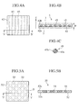
- Fig. 5A is a plan view of the polymer electrolyte layer including the distance defining members for the bipolar battery of the second embodiment according to the present invention
- Fig. 5B is a cross section, taken along line V-V of Fig. 5A, of the polymer electrolyte layer including such distance defining members.
- the polymer electrolyte layer 50 is comprised of a polymer electrolyte 52 in which the distance defining members 55 are embedded.
- the distance defining members 55 are formed in a porous sheet with a plurality of wire-like members, described above with reference to the first embodiment, being disposed not in parallel but in a lattice form.
- Materials to be used for the distance defining members 55 are similar to those of the first embodiment and may include resin fibers or metallic thin wires with their surfaces coated with resin.
- the polymer electrolyte layer 50 in which the distance defining members 55 are berried, is fabricated in a process described below.
- a 200 mesh SUS net 55 (a porous sheet with a cross sectional structure similar to that of Fig. 4C: mesh means number of fibers per inch) whose surface is coated with PP is placed onto a PET film 52a and, then, a mixture of polymer (co-polymer of PEO and PPO), supporting salt (LiN(SO 2 C 2 F 5 ) 2 ) and ultraviolet polymerization initiator (benzyldimethyl-ketal) is coated over the resulting PET film. And, further superposed on the PET film thus coated is another PET film 52b, with polymerization being initiated through ultraviolet radiation to form the polymer electrolyte layer 50.
- the polymer electrolyte layer 50 can be formed in a structure with the specified portions thereof being formed of the distance defining members 55 but the other major portion thereof being formed of the polymer electrolyte 52 to enable favorable ion transfer.
- the PET films 52a, 52b are conceptually shown, in actual practice, a boundary between the PET films 52a, 52b substantially disappears upon formation of the polymer electrolyte layer 50.
- a polymer battery of a third embodiment according to the present invention and its related method are described in detail mainly with reference to Figs. 6A and 6B.
- the polymer battery i.e., a bipolar battery, of this embodiment, differ in structure from that of the first embodiment in respect of distance defining members of a polymer electrolyte layer and is similar in other respects. Therefore, this embodiment is described aiming at such differential aspects and like component parts bear the same reference numerals to suitably simplify description or to omit description.
- Fig. 6A is a plan view of the polymer electrolyte layer including the distance defining members for the bipolar battery of the third embodiment according to the present invention
- Fig. 6B is a cross section, taken along line VI-VI of Fig. 6A, of the polymer electrolyte layer including such distance defining members.
- the polymer electrolyte layer 60 is comprised of a polymer electrolyte 62 in which the distance defining members 65 are embedded.
- the distance defining members 65 are formed in a porous sheet with a single piece of or a plurality of wire-like members getting entangled in a nonwoven state.
- the widths of the distance defining members 65 are omitted in Fig. 6A.
- Materials to be used for the distance defining members 65 are similar to those of the first embodiment and may include resin fibers or metallic thin wires with their surfaces coated with resin.
- the use of such resin fibers or metallic thin wires with their surfaces coated with resin which are arranged not to get woven but to get entangled in the nonwoven state allows the porous sheet for the distance defining member 65 to be formed.
- the polymer electrolyte layer 60 in which the distance defining members 65 are berried, is fabricated in a process described below.
- a spun bond nonwoven fabric 65 (nonwoven fabric formed by thermally welding fibers to one another without binder: a porous sheet) composed of PP fibers each with a wire diameter of 20 ⁇ m is placed onto a PET film 62a and, then, a mixture of polymer (co-polymer of PEO and PPO), supporting salt (LiN(SO 2 C 2 F 5 ) 2 ) and ultraviolet polymerization initiator (benzyldimethyl-ketal) is coated over the resulting PET film. And, further superposed on the PET film 62a thus coated is another PET film 62b, with polymerization being achieved through ultraviolet radiation to form the polymer electrolyte layer 60.
- a mixture of polymer co-polymer of PEO and PPO
- supporting salt LiN(SO 2 C 2 F 5 ) 2
- ultraviolet polymerization initiator benzyldimethyl-ketal
- the polymer electrolyte layer 60 can be formed in a structure with the specified portions thereof being formed of the distance defining members 65 but the other major portion thereof being formed of the polymer electrolyte 62 to enable favorable ion transfer.
- the PET films 62a, 62b are conceptually shown, in actual practice, a boundary between the PET films 62a, 62b substantially disappears upon formation of the polymer electrolyte layer 60 like in the first embodiment.
- a polymer battery of a fourth embodiment according to the present invention and its related method are described in detail mainly with reference to Figs. 7A and 7B.
- the polymer battery i.e., a bipolar battery, of this embodiment, differ in structure from that of the first embodiment in respect of distance defining members of a polymer electrolyte layer and is similar in other respects. Therefore, this embodiment is described aiming at such differential aspects and like component parts bear the same reference numerals to suitably simplify description or to omit description.
- Fig. 7A is a plan view of the polymer electrolyte layer including the distance defining members for the bipolar battery of the fourth embodiment according to the present invention
- Fig. 7B is a cross section, taken along line VII-VII of Fig. 7A, of the polymer electrolyte layer including such distance defining members.
- the polymer electrolyte layer 70 is comprised of a polymer electrolyte 72 in which the distance defining members 75 are embedded.
- the distance defining members 75 are comprised of a plurality of small sized wire-like fragments that are randomly dispersed.
- Materials to be used for the small fragments of the distance defining members 75 may include ceramics.
- ceramic material may include alumina (Al 2 O 3 ), SiO 2 and ZrO 2 .
- Al 2 O 3 alumina
- SiO 2 alumina
- ZrO 2 alumina
- the polymer electrolyte layer 70 in which the distance defining members 75 are berried, is fabricated in a process described below.
- a mixture of polymer (co-polymer of PEO and PPO), supporting salt (LiN(SO 2 C 2 F 5 ) 2 ) and ultraviolet polymerization initiator (benzyldimethyl-ketal) is coated on a PET film 72a and, then, needle-shaped alumina fragments 75 are randomly disposed. And, further superposed on the PET film 72a, on which the alumina fragments are disposed, is another PET film 72b, with polymerization being achieved through ultraviolet radiation to form the polymer electrolyte layer 70.
- the polymer electrolyte layer 70 can be formed in a structure with the specified portions thereof being formed of the distance defining members 75 but the other major portion thereof being formed of the polymer electrolyte 72 to enable favorable ion transfer.
- the PET films 72a, 72b are conceptually shown, in actual practice, a boundary between the PET films 72a, 72b substantially disappears upon formation of the polymer electrolyte layer 70 like in the first embodiment.
- a polymer battery of a fifth embodiment according to the present invention and its related method are described in detail mainly with reference to Figs. 8A and 8B.
- the polymer battery i.e., a bipolar battery, of this embodiment, differ in structure from that of the first embodiment in respect of distance defining members of a polymer electrolyte layer and is similar in other respects. Therefore, this embodiment is described aiming at such differential aspects and like component parts bear the same reference numerals to suitably simplify description or to omit description.
- Fig. 8A is a plan view of the polymer electrolyte layer including the distance defining members for the bipolar battery of the fifth embodiment according to the present invention
- Fig. 8B is a cross section, taken along line VIII-VIII of Fig. 8A, of the polymer electrolyte layer including such distance defining members.
- the polymer electrolyte layer 80 is comprised of a polymer electrolyte 82 in which the distance defining members 85 are embedded.
- the distance defining members 85 are comprised of a plurality of small spherical balls which are randomly disposed in structure.
- Materials to be used for the small spherical balls 85 may include resin, metallic balls with surfaces coated with resin and, in addition to these materials, may include small ceramic balls like in the fourth embodiment.
- resin fibers include PP, PE, PET, polyamide synthetic fiber, polyimide and silicone, and as ceramic materials, alumina (Al 2 O 3 ), SiO 2 and ZrO 2 may be used. Of course, no limitation is intended to these materials.
- the polymer electrolyte layer 80 in which the distance defining members 85 are berried, is fabricated in a process described below.
- a mixture of polymer (co-polymer of PEO and PPO), supporting salt (LiN(SO 2 C 2 F 5 ) 2 ) and ultraviolet polymerization initiator (benzyldimethyl-ketal) is coated on a PET film 82a and, then, polymer beads 85 with diameter of 20 ⁇ m are randomly disposed. And, further superposed on the PET film 82a, on which the polymer beads are disposed, is another PET film 82b, with polymerization being achieved through ultraviolet radiation to form the polymer electrolyte layer 80.
- the polymer electrolyte layer 80 can be formed in a structure with the specified portions thereof being formed of the distance defining members 85 but the other major portion thereof being formed of the polymer electrolyte 82 to enable favorable ion transfer.
- the PET films 82a, 82b are conceptually shown, in actual practice, a boundary between the PET films 82a, 82b substantially disappears upon formation of the polymer electrolyte layer 80 like in the first embodiment.
- distance defining members 45, 55, 65, 75, 85 of the respective embodiments set forth above can be used in suitable combination.
- the polymer electrolyte layers 4, 50, 60, 70, 80 are formed to include the distance defining members 45, 55, 65, 75, 85 of the various variations, respectively. Accordingly, application of such polymer electrolyte layers to the bipolar battery provides the following advantageous benefits.
- the polymer solid electrolyte layer with no introduction of the distance defining members was prepared that had a thickness of 100 ⁇ m as a result of inability to achieve thin film formation because of a required mechanical strength.
- the polymer solid electrolyte layers each with the distance defining members being introduced and each with a thickness of 20 ⁇ m ware prepared for all structures of the first to fifth embodiments, respectively.
- the polymer solid electrolyte layer with no introduction of the distance defining members exhibited the resistance of 642 ⁇ .
- the polymer solid electrolyte layer introducing the distance defining members formed of the plural wire-like resins disposed in substantially parallel to one another with the given distances in accordance with the first embodiment had the resistance of 135 ⁇ .
- the polymer solid electrolyte layer introducing the distance defining members formed of the metallic wires, each having the surface coated with resin, disposed in the lattice form in accordance with the second embodiment had the resistance of 161 ⁇ .
- the polymer solid electrolyte layer introducing the distance defining members formed of the single piece of or the plural of wire-like members entangled in the nonwoven form in accordance with the third embodiment had the resistance of 156 ⁇ .
- the polymer solid electrolyte layer introducing the distance defining members formed of the plural wire-like small fragments randomly disposed in accordance with the fourth embodiment had the resistance of 130 ⁇ .
- the polymer solid electrolyte layer introducing the distance defining members formed of the plural small balls randomly disposed in accordance with the fifth embodiment had the resistance of 129 ⁇ .
- bipolar batteries were prepared each of which had the polymer electrolyte layers each with a thickness of 20 ⁇ m regardless of whether the distance defining members are introduced or not introduced and each of which included ten stacks of unit cell layers. And, after completion, the bipolar batteries were charged and output voltages of respective unit cell layers were measured.
- the polymer electrolyte includes opening portions, shown in Figs. 5A and 6A, in size of an area S equal to or greater than 1 mm 2 . Since the opening portion with the area S in a range equal to or greater than 1 mm 2 is allowable, this results in a capability of increasing the ion conductivity.
- the present invention is not limited to such embodiments. While description has been illustratively made of the bipolar batteries, the present invention is not limited to such illustrations and the principle of the present invention can be applied to polymer batteries other than the bipolar batteries.
- This embodiment is related to a battery (battery module) composed of a plurality of pieces of the bipolar batteries of the respective embodiments set forth above.
- Fig. 9 is a schematic view illustrating the battery of the presently filed embodiment to which the polymer batteries of the first to fifth embodiments of the present invention can be applied.
- preparing a plurality of pieces of bipolar batteries 30 described above with reference to the first to the fifth embodiments, respectively, and connecting the positive terminals to one another and connecting the negative terminals to one another in parallel connection enable a battery 90 with a long durability to be obtained.
- the bipolar batteries 30 mutually connected in parallel in a simplified structure enables formation of the battery.
- the battery 90 is formed of a plurality of bipolar batteries 30, even if there is one defective in the bipolar batteries 30, mere replacement of one defective allows remaining other non-defectives to be left as they are, resulting in an excellent economy.
- the negative terminal of the bipolar battery can be consecutively connected to the positive terminal of the other bipolar battery 30 such that the bipolar batteries 30 are connected in series to be formed in the battery.
- Series connection enables the battery with a high power output to be obtained.
- This embodiment is related to a vehicle in which the bipolar batteries of the first to fifth embodiments or the battery of the sixth embodiment are installed a drive power source.
- Fig. 10 is a schematic view illustrating the vehicle of the presently filed embodiment in which the bipolar batteries of the first to fifth embodiments or the battery, to which such bipolar batteries are applied, are installed.
- the bipolar batteries 30 of the respective embodiments and the battery 90 have a variety of characteristics and, especially, they are compact batteries. For this reason, these batteries are preferable as a vehicle power supply in which severe demands are made in an energy density and a power density. Also, while if the polymer solid electrolyte is used for electrolyte 4, electrolyte 4 has a tendency in which the ion conductivity is lower than that of gel electrolyte, when using the battery in the vehicle 100, it is possible for a circumferential environment of the bipolar battery to be kept under a high temperature to some extent. From this viewpoint, it can be said that the bipolar batteries 30 of the respective embodiments and the battery 90 can be preferable to be used in the vehicle 100.
- the distance defining members included in the polymer electrolyte layer since the distance defining members provide a high mechanical strength, even if the polymer electrolyte layer is made to be small in thickness, an overall strength is strongly enhanced and the presence of the distance defining members interposed between the positive electrode active material layer and the negative electrode active material layer enables these components parts to be prevented from being brought into contact with one another for thereby preventing short-circuiting.
Landscapes
- Chemical & Material Sciences (AREA)
- Chemical Kinetics & Catalysis (AREA)
- Electrochemistry (AREA)
- General Chemical & Material Sciences (AREA)
- Engineering & Computer Science (AREA)
- Manufacturing & Machinery (AREA)
- Condensed Matter Physics & Semiconductors (AREA)
- Dispersion Chemistry (AREA)
- General Physics & Mathematics (AREA)
- Inorganic Chemistry (AREA)
- Physics & Mathematics (AREA)
- Materials Engineering (AREA)
- Secondary Cells (AREA)
- Cell Separators (AREA)
- Battery Electrode And Active Subsutance (AREA)
Abstract
Description
Claims (19)
- A polymer battery comprising:a positive electrode active material layer (2);a negative electrode active material layer (3) placed in opposition to the positive electrode active material layer;a polymer electrolyte layer (4) disposed between the positive electrode active material layer and the negative electrode active material layer; anda distance defining member (45, 55, 65, 75, 85) included in the polymer electrolyte layer to define a distance between the positive electrode active material layer and the negative electrode active material layer.
- The polymer battery according to claim 1, wherein the distance defining member (45, 55, 65, 75, 85) includes resin material.
- The polymer battery according to claim 2, wherein the resin material is a resin fabric (45, 55, 65, 75).
- The polymer battery according to claim 2, wherein the resin material is a porous sheet (55, 65) obtained by processing a resin fabric.
- The polymer battery according to claim 4, wherein the porous sheet (55, 65) is formed with openings portions each with an area equal to or greater than 1 mm2.
- The polymer battery according to claim 2, wherein the resin material is a resin ball (85).
- The polymer battery according to claim 1, wherein the distance defining member (45, 55, 65, 75, 85) includes a metallic material whose surface is coated with resin.
- The polymer battery according to claim 7, wherein the distance defining member (45, 55, 65, 75) is a metallic wire whose surface is coated with the resin.
- The polymer battery according to claim 8, wherein the distance defining member is a porous sheet (55, 65) obtained by processing the metallic wire.
- The polymer battery according to claim 9, wherein the porous sheet (55, 65) is formed with openings portions each with an area equal to or greater than 1 mm2.
- The polymer battery according to claim 7, wherein the distance defining member (85) is a metallic ball whose surface is coated with the resin.
- The polymer battery according to any one of claims 1 to 11, further comprising:wherein a plurality of the bipolar electrodes are laminated in series between which the polymer electrolyte layer (4) is interposed.a current collector (10a, 10b), a bipolar electrode (10) being formed with the current collector one surface of which is formed with the positive electrode active material layer (2) and the other surface of which is formed with the negative electrode active material layer (3),
- The polymer battery according to any one of claims 1 to 12, wherein the positive electrode active material layer (2) includes composite oxide of lithium and transition metal, and the negative electrode active material layer (3) includes carbon or composite oxide of lithium and transition metal.
- The polymer battery according to any one of claims 1 to 13, wherein electrolyte of the polymer electrolyte layer (4) includes solid polymer electrolyte.
- The polymer battery according to any one of claims 1 to 14, wherein a plurality of pieces of the polymer batteries (30) are connected to form a battery (90).
- The polymer battery according to any one of claims 1 to 15, wherein the polymer battery (30) is applied to a drive power source for a vehicle (100).
- The polymer battery according to claim 15, wherein the battery (90) is applied to a drive power source for a vehicle (100).
- A polymer battery comprising:a positive electrode active material layer (2);a negative electrode active material layer (3) placed in opposition to the positive electrode active material layer;a polymer electrolyte layer (4) disposed between the positive electrode active material layer and the negative electrode active material layer; anddefining means (45, 55, 65, 75, 85), included in the polymer electrolyte layer, for defining a distance between the positive electrode active material layer and the negative electrode active material layer.
- A method of manufacturing a polymer battery, the method comprising:forming a polymer electrolyte layer (4), including a distance defining member (45, 55, 65, 75, 85), onto one of a positive electrode active material layer (2) and a negative electrode active material layer (3); andforming the other one of the positive electrode active material layer and the negative electrode active material layer onto the polymer electrolyte layer such that a distance between the positive electrode active material layer and the negative electrode active material layer is defined by the distance defining member.
Applications Claiming Priority (2)
| Application Number | Priority Date | Filing Date | Title |
|---|---|---|---|
| JP2002316039 | 2002-10-30 | ||
| JP2002316039A JP4135469B2 (en) | 2002-10-30 | 2002-10-30 | Polymer battery, battery pack and vehicle |
Publications (2)
| Publication Number | Publication Date |
|---|---|
| EP1422780A1 true EP1422780A1 (en) | 2004-05-26 |
| EP1422780B1 EP1422780B1 (en) | 2012-08-22 |
Family
ID=32171210
Family Applications (1)
| Application Number | Title | Priority Date | Filing Date |
|---|---|---|---|
| EP03020614A Expired - Lifetime EP1422780B1 (en) | 2002-10-30 | 2003-09-10 | Polymer battery and related method |
Country Status (3)
| Country | Link |
|---|---|
| US (3) | US7318979B2 (en) |
| EP (1) | EP1422780B1 (en) |
| JP (1) | JP4135469B2 (en) |
Cited By (4)
| Publication number | Priority date | Publication date | Assignee | Title |
|---|---|---|---|---|
| US7794877B2 (en) | 2005-05-03 | 2010-09-14 | Randy Ogg | Bi-polar rechargeable electrochemical battery |
| US8632901B2 (en) | 2007-10-26 | 2014-01-21 | G4 Synergetics, Inc. | Dish shaped and pressure equalizing electrodes for electrochemical batteries |
| US8859132B2 (en) | 2009-01-27 | 2014-10-14 | G4 Synergetics, Inc. | Variable volume containment for energy storage devices |
| US10581107B2 (en) | 2014-11-07 | 2020-03-03 | Semiconductor Energy Laboratory Co., Ltd. | Secondary battery and manufacturing method thereof |
Families Citing this family (22)
| Publication number | Priority date | Publication date | Assignee | Title |
|---|---|---|---|---|
| JPH07546U (en) * | 1991-10-16 | 1995-01-06 | ピアス株式会社 | Two-liquid mixing spray device and spray body in the spray device |
| SE527979C2 (en) * | 2004-05-07 | 2006-07-25 | Effpower Ab | End electrode for bipolar battery, biolayer battery and method for producing end electrode |
| US7776478B2 (en) * | 2005-07-15 | 2010-08-17 | Cymbet Corporation | Thin-film batteries with polymer and LiPON electrolyte layers and method |
| KR100705738B1 (en) | 2005-09-16 | 2007-04-09 | 강봉섭 | Lithium secondary battery having divided electrolyte |
| JP2007087680A (en) * | 2005-09-21 | 2007-04-05 | Tomoegawa Paper Co Ltd | Electrode-polyelectrolyte film complex for electronic component and its manufacturing method |
| JP2007273436A (en) * | 2006-03-08 | 2007-10-18 | Idemitsu Kosan Co Ltd | Solid electrolyte sheet |
| JP4274256B2 (en) * | 2006-08-25 | 2009-06-03 | トヨタ自動車株式会社 | Electrode for power storage device and power storage device |
| JP2008146917A (en) * | 2006-12-07 | 2008-06-26 | Nippon Synthetic Chem Ind Co Ltd:The | All-solid lithium secondary battery |
| JP2010177162A (en) * | 2009-02-02 | 2010-08-12 | Konica Minolta Holdings Inc | Method for manufacturing secondary battery |
| FR2964256B1 (en) * | 2010-08-24 | 2012-09-28 | Commissariat Energie Atomique | BIPOLAR ELECTROCHEMICAL ACCUMULATOR WITH IMPROVED PACKAGING |
| US9853325B2 (en) | 2011-06-29 | 2017-12-26 | Space Charge, LLC | Rugged, gel-free, lithium-free, high energy density solid-state electrochemical energy storage devices |
| US11996517B2 (en) | 2011-06-29 | 2024-05-28 | Space Charge, LLC | Electrochemical energy storage devices |
| US11527774B2 (en) | 2011-06-29 | 2022-12-13 | Space Charge, LLC | Electrochemical energy storage devices |
| US10601074B2 (en) | 2011-06-29 | 2020-03-24 | Space Charge, LLC | Rugged, gel-free, lithium-free, high energy density solid-state electrochemical energy storage devices |
| CN103855360B (en) * | 2014-02-27 | 2016-08-17 | 宁德新能源科技有限公司 | Lithium ion battery and cathode pole piece thereof and preparation method |
| DE102015210806A1 (en) * | 2014-11-14 | 2016-05-19 | Hyundai Motor Company | Bipolar electrode, bipolar all-solid-state battery manufactured using same, and manufacturing method thereof |
| JP6487712B2 (en) * | 2015-02-23 | 2019-03-20 | 昭和電工パッケージング株式会社 | Power storage device |
| EP3762989A4 (en) | 2018-03-07 | 2021-12-15 | Space Charge, LLC | Thin-film solid-state energy-storage devices |
| JP7014899B2 (en) * | 2018-04-27 | 2022-02-01 | 富士フイルム株式会社 | Solid electrolyte-containing sheets, electrode sheets for all-solid-state secondary batteries, all-solid-state secondary batteries, electronic devices and electric vehicles, and methods for manufacturing these. |
| CN112421100A (en) * | 2019-08-21 | 2021-02-26 | 南京博驰新能源股份有限公司 | Preparation method and application of glued solid electrolyte membrane |
| CN110676420B (en) * | 2019-10-30 | 2022-04-12 | 复阳固态储能科技(溧阳)有限公司 | Lithium ion battery's lithium diaphragm of mending |
| US20240006663A1 (en) * | 2021-03-16 | 2024-01-04 | Vehicle Energy Japan Inc. | Solid electrolyte sheet, and solid electrolyte secondary battery using said solid electrolyte sheet |
Citations (6)
| Publication number | Priority date | Publication date | Assignee | Title |
|---|---|---|---|---|
| US5521023A (en) * | 1990-08-16 | 1996-05-28 | Kejha; Joseph B. | Composite electrolytes for electrochemical devices |
| US5631103A (en) * | 1996-09-27 | 1997-05-20 | Motorola, Inc. | Highly filled solid polymer electrolyte |
| EP0938150A2 (en) * | 1998-02-18 | 1999-08-25 | Matsushita Electric Industrial Co., Ltd. | Polymer electrolyte battery |
| WO2001091220A1 (en) * | 2000-05-22 | 2001-11-29 | Korea Institute Of Science And Technology | A hybrid polymer electrolyte fabricated by a spray method, a lithium secondary battery comprising the hybrid polymer electrolyte and their fabrication methods |
| US6413676B1 (en) * | 1999-06-28 | 2002-07-02 | Lithium Power Technologies, Inc. | Lithium ion polymer electrolytes |
| WO2002061874A1 (en) * | 2001-01-31 | 2002-08-08 | Korea Institute Of Science And Technology | A multi-layered, uv-cured polymer electrolyte and lithium secondary battery comprising the same |
Family Cites Families (17)
| Publication number | Priority date | Publication date | Assignee | Title |
|---|---|---|---|---|
| US1484927A (en) * | 1922-02-25 | 1924-02-26 | Union Carbide & Carbon Res Lab | Storage-battery separator and process of making the same |
| GB2160701B (en) * | 1984-06-22 | 1988-02-24 | Chloride Group Plc | Separators for recombination electric storage cells |
| US5773168A (en) * | 1995-08-23 | 1998-06-30 | Kabushiki Kaisha Toshiba | Nonaqueous electrolyte secondary battery and method for manufacturing the same |
| US5766789A (en) * | 1995-09-29 | 1998-06-16 | Energetics Systems Corporation | Electrical energy devices |
| JP3620142B2 (en) | 1996-02-27 | 2005-02-16 | カシオ計算機株式会社 | Battery and manufacturing method thereof |
| JP3443257B2 (en) | 1996-11-11 | 2003-09-02 | 三洋電機株式会社 | Solid electrolyte battery |
| EP0896374B1 (en) * | 1996-12-24 | 2011-12-07 | Kao Corporation | Nonaqueous electrolyte secondary battery |
| JPH11345629A (en) | 1998-03-31 | 1999-12-14 | Canon Inc | Secondary battery and production of the same |
| JPH11307124A (en) * | 1998-04-17 | 1999-11-05 | Mitsubishi Electric Corp | Secondary battery and its manufacture |
| US6580026B1 (en) * | 1999-06-30 | 2003-06-17 | Catalysts & Chemicals Industries Co., Ltd. | Photovoltaic cell |
| JP2001118601A (en) | 1999-10-18 | 2001-04-27 | Toyota Motor Corp | Manufacturing method of lithium ion secondary battery |
| JP2001332304A (en) * | 2000-05-24 | 2001-11-30 | Sony Corp | Electrolyte and cell using the same |
| JP2001357882A (en) | 2000-06-13 | 2001-12-26 | Mitsubishi Chemicals Corp | Flat plate-layered battery |
| JP2002015772A (en) | 2000-06-30 | 2002-01-18 | Toyota Central Res & Dev Lab Inc | Lithium secondary cell and manufacturing method of the same |
| JP2002184466A (en) | 2000-12-12 | 2002-06-28 | Mitsubishi Chemicals Corp | Battery for portable equipment |
| JP2002216846A (en) | 2001-01-18 | 2002-08-02 | Nissan Motor Co Ltd | Sheet-shaped cell |
| JP5163439B2 (en) * | 2008-11-19 | 2013-03-13 | Tdk株式会社 | FIBER-CONTAINING POLYMER FILM AND METHOD FOR PRODUCING SAME, ELECTROCHEMICAL DEVICE AND METHOD FOR PRODUCING SAME |
-
2002
- 2002-10-30 JP JP2002316039A patent/JP4135469B2/en not_active Expired - Fee Related
-
2003
- 2003-09-10 US US10/658,456 patent/US7318979B2/en active Active
- 2003-09-10 EP EP03020614A patent/EP1422780B1/en not_active Expired - Lifetime
-
2007
- 2007-11-21 US US11/984,724 patent/US8357463B2/en active Active
-
2012
- 2012-12-21 US US13/725,032 patent/US9203110B2/en not_active Expired - Fee Related
Patent Citations (6)
| Publication number | Priority date | Publication date | Assignee | Title |
|---|---|---|---|---|
| US5521023A (en) * | 1990-08-16 | 1996-05-28 | Kejha; Joseph B. | Composite electrolytes for electrochemical devices |
| US5631103A (en) * | 1996-09-27 | 1997-05-20 | Motorola, Inc. | Highly filled solid polymer electrolyte |
| EP0938150A2 (en) * | 1998-02-18 | 1999-08-25 | Matsushita Electric Industrial Co., Ltd. | Polymer electrolyte battery |
| US6413676B1 (en) * | 1999-06-28 | 2002-07-02 | Lithium Power Technologies, Inc. | Lithium ion polymer electrolytes |
| WO2001091220A1 (en) * | 2000-05-22 | 2001-11-29 | Korea Institute Of Science And Technology | A hybrid polymer electrolyte fabricated by a spray method, a lithium secondary battery comprising the hybrid polymer electrolyte and their fabrication methods |
| WO2002061874A1 (en) * | 2001-01-31 | 2002-08-08 | Korea Institute Of Science And Technology | A multi-layered, uv-cured polymer electrolyte and lithium secondary battery comprising the same |
Cited By (4)
| Publication number | Priority date | Publication date | Assignee | Title |
|---|---|---|---|---|
| US7794877B2 (en) | 2005-05-03 | 2010-09-14 | Randy Ogg | Bi-polar rechargeable electrochemical battery |
| US8632901B2 (en) | 2007-10-26 | 2014-01-21 | G4 Synergetics, Inc. | Dish shaped and pressure equalizing electrodes for electrochemical batteries |
| US8859132B2 (en) | 2009-01-27 | 2014-10-14 | G4 Synergetics, Inc. | Variable volume containment for energy storage devices |
| US10581107B2 (en) | 2014-11-07 | 2020-03-03 | Semiconductor Energy Laboratory Co., Ltd. | Secondary battery and manufacturing method thereof |
Also Published As
| Publication number | Publication date |
|---|---|
| US20040086781A1 (en) | 2004-05-06 |
| US7318979B2 (en) | 2008-01-15 |
| EP1422780B1 (en) | 2012-08-22 |
| US8357463B2 (en) | 2013-01-22 |
| JP4135469B2 (en) | 2008-08-20 |
| US20130136999A1 (en) | 2013-05-30 |
| US9203110B2 (en) | 2015-12-01 |
| US20080268337A1 (en) | 2008-10-30 |
| JP2004152596A (en) | 2004-05-27 |
Similar Documents
| Publication | Publication Date | Title |
|---|---|---|
| US9203110B2 (en) | Polymer battery and related method | |
| US7320846B2 (en) | Bipolar battery and method for manufacturing the same | |
| US8663833B2 (en) | Bipolar secondary battery, battery assembly formed by connecting said batteries and vehicle mounting same | |
| KR101543065B1 (en) | Electrode assembly and electrochemical cell containing the same | |
| KR101510518B1 (en) | Fabricating method of electrode assembly | |
| JP5697276B2 (en) | Electrode assembly having novel structure and method of manufacturing the same | |
| JP5233435B2 (en) | Bipolar secondary battery | |
| US11539101B2 (en) | Nonaqueous electrolyte secondary battery | |
| KR101489129B1 (en) | Bipolar electrode, bipolar secondary battery using same, and method for producing bipolar electrode | |
| EP1424744A1 (en) | Stacked battery, assembled battery and vehicle | |
| KR20130118764A (en) | Electrode assembly, battery cell and device comprising the same | |
| JP2005011660A (en) | Secondary battery electrode, manufacturing method of the same, and secondary battery using the same | |
| JP2005149891A (en) | Bipolar battery and packed battery using the same | |
| JP2005276486A (en) | Laminated battery, battery pack, and vehicle | |
| JP2004139775A (en) | Laminated battery, battery pack and vehicle | |
| JP2009211949A (en) | Nonaqueous electrolyte secondary battery | |
| US10468638B2 (en) | Method for forming a pouch for a secondary battery | |
| JP2006128038A (en) | Battery structure body | |
| JP2009302074A (en) | Electrode for secondary battery | |
| JP5376036B2 (en) | Nonaqueous electrolyte secondary battery | |
| JP7501971B2 (en) | Electrode assembly with outer fixing frame and lithium secondary battery including the same | |
| JP2005317468A (en) | Bipolar electrode, method of manufacturing bipolar electrode, bipolar battery, battery pack and vehicle with these mounted thereon | |
| EP4044331A1 (en) | Pouch-type secondary battery having increased energy density, and method for manufacturing same | |
| US20240283009A1 (en) | Sulfide electrolyte layer supported dry process electrode layer | |
| KR20240060210A (en) | Pouch-type battery cell jig device, pouch-type battary cell manufacturing device and pouch-type battery cell manufacturing method |
Legal Events
| Date | Code | Title | Description |
|---|---|---|---|
| PUAI | Public reference made under article 153(3) epc to a published international application that has entered the european phase |
Free format text: ORIGINAL CODE: 0009012 |
|
| 17P | Request for examination filed |
Effective date: 20030910 |
|
| AK | Designated contracting states |
Kind code of ref document: A1 Designated state(s): AT BE BG CH CY CZ DE DK EE ES FI FR GB GR HU IE IT LI LU MC NL PT RO SE SI SK TR |
|
| AX | Request for extension of the european patent |
Extension state: AL LT LV MK |
|
| AKX | Designation fees paid |
Designated state(s): DE FR GB |
|
| 17Q | First examination report despatched |
Effective date: 20050128 |
|
| 17Q | First examination report despatched |
Effective date: 20050128 |
|
| REG | Reference to a national code |
Ref country code: DE Ref legal event code: R079 Ref document number: 60341874 Country of ref document: DE Free format text: PREVIOUS MAIN CLASS: H01M0010400000 Ipc: H01M0010052500 |
|
| GRAP | Despatch of communication of intention to grant a patent |
Free format text: ORIGINAL CODE: EPIDOSNIGR1 |
|
| RIC1 | Information provided on ipc code assigned before grant |
Ipc: H01M 10/04 20060101ALI20120417BHEP Ipc: H01M 10/0565 20100101ALI20120417BHEP Ipc: H01M 2/14 20060101ALI20120417BHEP Ipc: H01M 10/0525 20100101AFI20120417BHEP Ipc: H01M 2/18 20060101ALI20120417BHEP Ipc: H01M 2/16 20060101ALI20120417BHEP Ipc: H01M 6/40 20060101ALI20120417BHEP Ipc: H01M 4/60 20060101ALI20120417BHEP |
|
| GRAS | Grant fee paid |
Free format text: ORIGINAL CODE: EPIDOSNIGR3 |
|
| GRAA | (expected) grant |
Free format text: ORIGINAL CODE: 0009210 |
|
| AK | Designated contracting states |
Kind code of ref document: B1 Designated state(s): DE FR GB |
|
| REG | Reference to a national code |
Ref country code: GB Ref legal event code: FG4D |
|
| REG | Reference to a national code |
Ref country code: DE Ref legal event code: R096 Ref document number: 60341874 Country of ref document: DE Effective date: 20121018 |
|
| PLBE | No opposition filed within time limit |
Free format text: ORIGINAL CODE: 0009261 |
|
| STAA | Information on the status of an ep patent application or granted ep patent |
Free format text: STATUS: NO OPPOSITION FILED WITHIN TIME LIMIT |
|
| 26N | No opposition filed |
Effective date: 20130523 |
|
| REG | Reference to a national code |
Ref country code: DE Ref legal event code: R097 Ref document number: 60341874 Country of ref document: DE Effective date: 20130523 |
|
| REG | Reference to a national code |
Ref country code: FR Ref legal event code: PLFP Year of fee payment: 14 |
|
| REG | Reference to a national code |
Ref country code: FR Ref legal event code: PLFP Year of fee payment: 15 |
|
| REG | Reference to a national code |
Ref country code: FR Ref legal event code: PLFP Year of fee payment: 16 |
|
| PGFP | Annual fee paid to national office [announced via postgrant information from national office to epo] |
Ref country code: FR Payment date: 20210812 Year of fee payment: 19 |
|
| PGFP | Annual fee paid to national office [announced via postgrant information from national office to epo] |
Ref country code: GB Payment date: 20210805 Year of fee payment: 19 Ref country code: DE Payment date: 20210803 Year of fee payment: 19 |
|
| REG | Reference to a national code |
Ref country code: DE Ref legal event code: R119 Ref document number: 60341874 Country of ref document: DE |
|
| GBPC | Gb: european patent ceased through non-payment of renewal fee |
Effective date: 20220910 |
|
| PG25 | Lapsed in a contracting state [announced via postgrant information from national office to epo] |
Ref country code: FR Free format text: LAPSE BECAUSE OF NON-PAYMENT OF DUE FEES Effective date: 20220930 Ref country code: DE Free format text: LAPSE BECAUSE OF NON-PAYMENT OF DUE FEES Effective date: 20230401 |
|
| PG25 | Lapsed in a contracting state [announced via postgrant information from national office to epo] |
Ref country code: GB Free format text: LAPSE BECAUSE OF NON-PAYMENT OF DUE FEES Effective date: 20220910 |