EP1422674A1 - AUTOMATIC MONEY TRANSACTING APPARATUS, AND PAPER CURRENCY UNIT HAVING BUILT−IN CAMERA - Google Patents
AUTOMATIC MONEY TRANSACTING APPARATUS, AND PAPER CURRENCY UNIT HAVING BUILT−IN CAMERA Download PDFInfo
- Publication number
- EP1422674A1 EP1422674A1 EP01961224A EP01961224A EP1422674A1 EP 1422674 A1 EP1422674 A1 EP 1422674A1 EP 01961224 A EP01961224 A EP 01961224A EP 01961224 A EP01961224 A EP 01961224A EP 1422674 A1 EP1422674 A1 EP 1422674A1
- Authority
- EP
- European Patent Office
- Prior art keywords
- bill
- customer
- security camera
- teller machine
- automatic teller
- Prior art date
- Legal status (The legal status is an assumption and is not a legal conclusion. Google has not performed a legal analysis and makes no representation as to the accuracy of the status listed.)
- Granted
Links
Images


Classifications
-
- G—PHYSICS
- G07—CHECKING-DEVICES
- G07F—COIN-FREED OR LIKE APPARATUS
- G07F19/00—Complete banking systems; Coded card-freed arrangements adapted for dispensing or receiving monies or the like and posting such transactions to existing accounts, e.g. automatic teller machines
-
- G—PHYSICS
- G07—CHECKING-DEVICES
- G07F—COIN-FREED OR LIKE APPARATUS
- G07F19/00—Complete banking systems; Coded card-freed arrangements adapted for dispensing or receiving monies or the like and posting such transactions to existing accounts, e.g. automatic teller machines
- G07F19/20—Automatic teller machines [ATMs]
-
- G—PHYSICS
- G07—CHECKING-DEVICES
- G07F—COIN-FREED OR LIKE APPARATUS
- G07F19/00—Complete banking systems; Coded card-freed arrangements adapted for dispensing or receiving monies or the like and posting such transactions to existing accounts, e.g. automatic teller machines
- G07F19/20—Automatic teller machines [ATMs]
- G07F19/205—Housing aspects of ATMs
-
- G—PHYSICS
- G07—CHECKING-DEVICES
- G07F—COIN-FREED OR LIKE APPARATUS
- G07F19/00—Complete banking systems; Coded card-freed arrangements adapted for dispensing or receiving monies or the like and posting such transactions to existing accounts, e.g. automatic teller machines
- G07F19/20—Automatic teller machines [ATMs]
- G07F19/207—Surveillance aspects at ATMs
Definitions
- the present invention relates to an automatic teller machine and a bill unit with a built-in camera, more particularly relates to an automatic teller machine and bill unit with a built-in camera able to monitor the state of motion of the hand of a customer.
- it relates to an automatic teller machine and a bill unit with a built-in camera able to use the built-in camera to monitor the motion of the hand of a customer when the customer withdraws or deposits money.
- ATMs automatic teller machines handling cash
- the security cameras built into the ATMs have been installed at the tops of the ATMS, so under ordinary conditions have only been able to capture images of the upper torsos of customers withdrawing and depositing cash and have not been able to capture images of the state of motion of the hands of the customers. Therefore, in conventional ATMs, it was not possible to leave behind a surveillance record of customers unintentionally forgetting to take their cash etc. Further, the security cameras installed at conventional ATMs had lenses at easily visible positions at the tops of the ATMs, so customers easily became aware of the existence of the security cameras and therefore there was the defect that if mischievous or malicious customers etc. blocked the lenses when making transactions, the images of the customers could no longer be captured.
- an object of the present invention is to solve the problem of a conventional ATM with a built-in security camera and provide an automatic teller machine installing the security camera at a nonvisible location of the ATM so as not to allow the customer to become aware of the existence of the security camera and monitoring the state of movement of cash by the hand of the customer when withdrawing or depositing cash, in particular when withdrawing cash, so as to enable confirmation when trouble occurs over money and identification of individuals.
- Another object is to provide an automatic teller machine and bill unit with a built-in camera setting a security camera at a nonvisible location of the ATM so as to enable protection of the security camera itself.
- the ATM of the present invention for achieving the above objects is shown by the following first aspect to sixth aspect.
- the ATM of the first aspect is an ATM for automatic withdrawal and deposit of money in accordance with an operation by a customer, characterized by being provided with a bill receptacle opened and closed by a shutter and a security camera positioned at a predetermined location in the bill receptacle and able to capture an image when said shutter is opened.
- the ATM of the second aspect is an ATM of the first aspect characterized in that sensors for detecting insertion of a hand into the bill receptacle are provided at two predetermined locations in said bill receptacle inside of said shutter, and said security camera operates to capture the image at least when said sensors detect the insertion of a hand into said bill receptacle.
- the ATM of the third aspect is an ATM of the first aspect characterized in that sensors for detecting insertion of a hand into the bill receptacle are provided at two predetermined locations in said bill receptacle inside of said shutter, and one of said sensors is set in the vicinity of the bills at said bill receptacle and said security camera operates to capture the image when that sensor detects bills being taken out.
- the ATM of the fourth aspect is an ATM of the second or third aspect characterized in that it is provided with a time counting means for counting the time after said bill receptacle is opened by said shutter, and said security camera operates to capture the image when a count of said time counting means reaches a predetermined time in the state without the insertion of a hand into the bill receptacle being detected by said sensors.
- the ATM of the fifth aspect is an ATM of the first to fourth aspects characterized in that a second security camera is installed at another portion of said ATM in addition to the security camera installed in said bill receptacle.
- the ATM of the sixth aspect is an ATM of the fifth aspect characterized in that the ranges of capture of the security camera installed in said bill receptacle and said second security camera are made different so as to capture the image of the customer in a state without any dead angles.
- the bill unit with a built-in security camera of the present invention for achieving the above objects is a bill unit for the withdrawal and deposit of bills built into an automatic teller machine for automatic withdrawal and deposit of money in accordance with an operation by a customer, characterized by being provided with a bill holder positioned at a back side of an opening/closing type shutter provided at said automatic teller machine, a sensor provided at an opening of said bill holder and detecting insertion of the hand of a customer into said bill holder, and a security camera positioned in the vicinity of said bill holder and capturing an image when said sensor detects insertion of the hand of a customer.
- the ATM of the present invention it is possible to monitor the state of movement of cash by the hand of a customer when withdrawing or depositing cash, in particular when withdrawing cash, without allowing the customer to become aware of the existence of the security camera, so confirmation when trouble over money occurs and identification of the individual involved become possible. Further, since the existence of the security camera is difficult for the customer to become aware of, it is also possible to protect the security camera itself.
- the bill unit with the built-in security camera of the present invention can be sold as a separate component, so can be introduced into various ATMs.
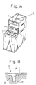
- FIG. 1A shows the appearance of a conventional ATM 9.
- the front side of the ATM 9 is shaped as a table. This portion has a touch panel type input panel.
- a bill receptacle 2 At the rear of the touch panel 1 are arrayed a bill receptacle 2 and a coin receptacle 3. Above these are provided a money card slot 4 and a passbook slot 5. Further, the top of the front panel of the ATM 9 is provided with a security camera 6.
- FIG. 1B is a partially enlarged sectional view of the structure of the bill receptacle 2 of the conventional ATM 9 shown in FIG. 1A.
- the bill receptacle 2 is usually blocked by a shutter 2A opening and closing in the horizontal direction.
- the shutter 2A opens, the bill holder 2B holding the bills appears.
- Deposited bills and withdrawn bills are held here once in this bill holder 2B.
- the opening of the bill holder 2B is provided with a hand insertion sensor 2C provided with a light emitting part and a light receiving part and can detect the deposition of bills or the withdrawal of bills by a customer.
- FIG. 2A shows the position of installation of the security camera 6 provided in the conventional ATM 9 and its range of capture and the position of the bill receptacle 2.
- the security camera 6 is installed at the top of the front panel of the ATM 9, so when the security camera 6 captures the image of a customer, a video of the customer 7 such as shown in FIG. 2B is obtained.
- the security camera 6 Since the security camera 6 is installed at the top of the front panel of the ATM 9 in this way, under ordinary conditions, only the image of the upper torso of the customer 7 withdrawing or depositing cash can be captured. The state of motion of the hand of the customer 7 could not be captured. Therefore, with the conventional ATM 9, it was not possible to leave behind a surveillance record of the customer 7 unintentionally forgetting to take his or her cash. Further, the security camera 6 installed in the conventional ATM 9 had the lens at an easily visible position of the front panel of the ATM 9, so the customer 7 could easily notice the existence of the security camera 6. When there was a mischievous or malicious customer 7, there was the problem that the lens was blocked at the time of the transaction and therefore the image of the customer could not be captured.
- FIG. 3A shows the appearance of an ATM 10 of the present invention. Note that to facilitate understanding of the explanation, portions the same as the conventional ATM 9 explained in FIG. 1A are given the same reference numerals in the explanation.
- the front surface is shaped as a table. This portion is provided with a touch panel type input panel 1. Further, behind this touch panel 1 are arranged a bill receptacle 2 and a coin receptacle 3. Above these are provided a money card slot 4 and a passbook slot 5. At the top of the front panel of the ATM 10 is provided a security camera 6.
- the shutter 2A opening/closing the bill receptacle 2 is provided in a table shape and moved in the horizontal direction.
- the portion of the front panel of the ATM 10 where the money card slot 4 and passbook slot 5 are provided is slanted back, and a shutter 2A is provided at the slanted part of the front panel. Therefore, in the ATM 10 of the present invention, the shutter 2A descends to open the bill receptacle 2.
- FIG. 3B is a partially enlarged perspective view of the part of the bill receptacle 2 of the ATM 10 in the state with the shutter 2A of FIG. 3A opened. Deep inside it is provided a bill holder 2BA in the same way as the conventional example. Further, in the present invention, a security camera 8 is provided at a position in the bill receptacle 2 hidden by the shutter 2A and not visible from the outside when the shutter 2A is closed. The installation position of the security camera 8 should be a position which can view the entire bill holder 2B.
- the bill receptacle 2 of the ATM 10 of the present invention is provided with two hand insertion sensors 11, 12.
- the first hand insertion sensor 11 and second hand insertion sensor 12 are comprised of light emitting parts and light receiving parts. Sensor beams SB1 and SB2 run between them. Infrared sensors may be used for the first hand insertion sensor 11 and the second hand insertion sensor 12, but it is also possible to use motion detection sensors detecting moving objects etc. as well.
- the second hand insertion sensor 12 in the present invention was also provided in the conventional machine. In the past as well, this sensor detected a customer's insertion of a hand into the bill holder 2B, so it is possible to use this sensor as it is.
- the first hand insertion sensor 11 is provided near the back surface of the shutter 2A.
- the sensor beam SB1 of the first hand insertion sensor 11 is a beam parallel to the direction of opening/closing of the shutter 2A of the bill receptacle 2.
- the second hand insertion sensor 12 is provided in the vicinity of the opening of the bill holder 2B in the same way as in the conventional ATM 9.
- the sensor beam SB2 of the second hand insertion sensor 12 is a beam cutting across the opening of the bill holder 2B and is designed to be able to detect the insertion of bills by the customer into the bill holder 2B or the removal of bills from the bill holder 2B. In this way, in the present invention, it becomes possible to capture an image from deep in the bill holder 2B of the ATM 10 and is possible to expand the range of capture for a short customer such as a customer using a wheelchair.
- FIG. 5A explains the installation position and range of capture of the security camera 8 provided at the ATM 10 of the present invention and the positions of the card unit 20, bill unit 30, and controller 40 built in the ATM 10.
- the security camera 6 provided in the conventional ATM 9 is also kept without being removed.
- the card unit 20 is provided at the rear of the money card slot 4 shown in FIG. 3A.
- the bill unit 30 is provided at the rear bottom of the bill receptacle 2. Further, at the bottommost part of the ATM 10, the controller 40 for controlling the operations of the devices inside the ATM 10 is provided.
- the video captured by the security cameras 6, 8 is designed to be recorded in multiple as a failsafe against loss of recordings.
- the media for recording video captured by the security cameras 6, 8 includes a CD-R drive 13 and a hard disk drive (hereinafter referred to as the "HDD") 14 built into the controller 40 and a video tape recorder (hereinafter referred to as a "VTR") 15 provided outside of the ATM 10.
- the image recorded in the VTR 15 can be monitored by a supervisor etc. by provision of a video monitor outside of the ATM 10. In this way, in this embodiment, even if two of the recorders break down, it is possible to record and store the image by the remaining one.
- the recorders built into the controller 40 were explained using the CD-R drive 13 and HDD 14 as examples, but the recorders built into the controller 40 are not limited to these. It is also possible to use a magneto-optic disk (MO) drive, digital versatile disk (DVD) drive, or other recorder using a recording medium. That is, the recording media used in the present invention are not particularly limited in type so long as they can be connected to a computer.
- MO magneto-optic disk
- DVD digital versatile disk
- the video of the customer captured by the security camera 6 is the same as that in the past. Further, the video of the customer 7 captured by the security camera 8 shows down to the hand of the customer 7 as shown in FIG. 5B since the security camera 8 is provided in the bill receptacle 2. Therefore, in the ATM 10 of the present invention, it is possible to record the state of the bills 31 being taken out from the bill holder 2B of the bill receptacle 2 by the customer 7.
- the ATM 10 of the present invention by operating both the conventionally provided security camera 6 and the security camera 8 newly provided in the present invention, it is possible to record both the image of the state of the surroundings including the upper torso of the customer 7 withdrawing or depositing cash and the image of the hand of the customer 7 at the time of withdrawal. Therefore, in the ATM 10 of the present invention, it is possible to kept a surveillance record of a customer 7 unintentionally forgetting to take his or her cash etc.
- the security camera 8 installed in the ATM 10 of the present invention is not visible until the shutter 2A of the bill receptacle 2 opens, and, once the shutter 2A opens, the attention of the customer 7 shifts to the bills stored in the bill holder 2B, so its existence is hard for a customer 7 to notice.
- the conventionally provided security camera 6 may also be made a dummy and only the security camera 8 newly provided in the present invention made to operate.
- FIG. 6 shows the connections of the devices provided inside the ATM 10 of the present invention.
- the shutter 2A, front panel camera 6, bill unit camera 8, the first and second hand insertion cameras 11, 12, CD-R drive 13, HDD 14, card unit 20, and bill unit 30 are connected to the controller 40. Further, the controller 40 records the video in the VTR 15 provided outside of the ATM 10 as well.
- FIG. 7 is a view of the configuration of the data showing an embodiment of the content of the video data captured by the security cameras 6, 8 of the ATM 10 of the present invention and recorded in the CD-R drive 13, HDD 14, and VTR 15.
- the recorded video data includes (1) transaction data including the transaction time and transaction content, (2) card embossed image data captured by the security camera 6 (account number, member number, expiration date, name, etc. printed on the surface of the money card or credit card by embossing), and video data captured by the security cameras 6, 8.
- the image and video recorded by the recorders built into the ATM 10 are stored together with the customer data, so by later referring to a past abnormal operation of a customer during use of the ATM 10 such as forgetting to take the cash or not taking all of it or card insertion, it is possible to confirm if the same person has performed that operation.
- the recording by the VTR 15 requires review of the entire video in order to refer to a specific recorded image
- the recording mechanism of a CD-R drive 13, HDD 14, etc. built into the ATM 10 enables search for a desired part of the video by an identification code of the operator and therefore enables immediate confirmation. Further, in the future, since the video is stored as data, confirmation of the identity of the customer by comparison of customer data and the recorded image becomes possible.
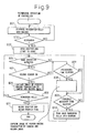
- FIG. 8 is a flow chart of the routine of an example of an operation for withdrawal of bills in the bill unit 30 in the withdrawal and deposit operations of the controller 40 built into the ATM 10 of the present invention.
- This routine is started when a customer touches the "WITHDRAWAL" button displayed on the input panel 1 shown in FIG. 3A.
- the flow chart of FIG. 8 describes the routine after the end of all routines such as the confirmation of the PIN of the customer after insertion of his or her card and confirmation of the withdrawal amount.
- step 801 the bills designated by the bill unit 30 are dispensed into the holder 2B.
- step 802 it is judged if the bills were able to be dispensed.
- the routine returns to step 801, where dispensing of cash is continued, while when the bills could be dispensed, the routine proceeds to step 803, where the shutter 2A is opened and simultaneously time starts to be counted.
- step 804 it is judged by the hand insertion sensors 11, 12 if the insertion of the hand of the customer has been detected.
- the routine proceeds to step 805, where the security cameras 6, 8 capture the image of the person making the transaction (customer) and record the image in the afore-mentioned CD-R drive 13, HDD 14, and VTR 15.
- step 806 it is judge if the holder 2B has any bills left in it. When bills are left in it, the routine returns to step 804, while when there are no bills left in it, the routine proceeds to step 811.
- step 811 the shutter 2A is closed, the counted time is cleared, and the routine is ended.
- step 804 the routine proceeds to step 807, where it is judged if a prescribed time has elapsed from when the shutter 2A was opened.
- step 807 the routine proceeds to step 809, where it is judged if the time for forcible recovery of the bills has elapsed.
- step 808 the image of the person making the transaction (customer) is captured by the security cameras 6, 8 and the image is recorded in the afore-mentioned CD-R drive 13, HDD 14, and VTR 15.
- step 809 When the time for forcible recovery has not elapsed in the judgment of step 809 whether the time for forcible recovery of the bill has elapsed, the routine returns to step 804, where whether the hand of the customer has been inserted is detected. When the time for forcible recovery has elapsed, the routine proceeds to step 810, where the bills remaining in the holder 2B are forcibly taken back into the machine and the routine ended.
- the image of the hand of the customer captured by the security camera 8 is kept in the CD-R drive 13, HDD 14, or VTR 15, so it is possible to easy confirm this fact when the customer realizing he or she has forgotten to take the cash later visits the bank to reclaim the forgotten money and therefore it is possible to prevent trouble with customers over money.
- FIG. 9 is a flow chart of the routine of another example of a withdrawal operation among the withdrawal and deposit operations of the controller 40 built in the ATM 10 of the present invention.
- This routine differs from the routine explained in FIG. 8 only on the point that an image of the customer is captured by the security camera 8 only when the second hand insertion sensor 12 installed in the opening of the bill holder 2B of the bill receptacle 2 detects insertion of a hand. Therefore, parts of the routine the same as the routine explained in FIG. 8 are assigned the same step numbers and explanations thereof are omitted.
- the first hand insertion sensor 11 detects whether a hand of the customer has been inserted.
- the second hand insertion sensor 12 detects whether the hand of the customer has been inserted.
- the routine proceeds to step 807, while when the second hand insertion sensor 12 detects the insertion of the hand of the customer, the routine proceeds to step 805, where the image of the person making the transaction (customer) is captured and the video is recorded in the afore-mentioned CD-R 13, HDD 14, and VTR 15.
- the camera captures the image of the customer when the second hand insertion sensor 12 detects the insertion of the hand of the customer, so it is possible to capture an image of the person actually taking out the bills.
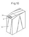
- FIG. 10 is a perspective view showing the configuration of the bill unit 30 provided with the security camera 8 as a separate unit. From this figure, it will be understood that the security camera 8 is set deep in the bill holder 2B of the bill unit 30. In this way, the bill unit 30 provided with the security camera 8 of the present invention can be sold as a separate unit as well.
- the configuration of the ATM shown in the present invention it is possible to make the customer monitoring at the time of handling cash more reliable and help prevent tampering with the security camera etc. Further, it is possible to divert the various sensors of the units of a conventional ATM to serve as triggers for capturing images of customers making cash transactions, so it is possible to capture images more accurately. Further, the customer is not longer made aware of being captured by the security camera due to the ordinary appearance.
- the security camera set in the vicinity of the bill holder shown in the present invention can be built into the bill unit, so it is possible to sell only the bill unit and thereby apply the present invention to a broad range of machines.
Landscapes
- Business, Economics & Management (AREA)
- Accounting & Taxation (AREA)
- Finance (AREA)
- Physics & Mathematics (AREA)
- General Physics & Mathematics (AREA)
- Financial Or Insurance-Related Operations Such As Payment And Settlement (AREA)
- Closed-Circuit Television Systems (AREA)
- Burglar Alarm Systems (AREA)
- Studio Devices (AREA)
- Control Of Vending Devices And Auxiliary Devices For Vending Devices (AREA)
- Cash Registers Or Receiving Machines (AREA)
Abstract
Description
Claims (7)
- An automatic teller machine for automatic withdrawal and deposit of money in accordance with an operation by a customer,
said automatic teller machine
characterized by being provided with:a bill receptacle opened and closed by a shutter anda security camera positioned at a predetermined location in said bill receptacle and able to capture an image when said shutter is opened. - An automatic teller machine as set forth in claim 1,
said automatic teller machine
characterized in that
sensors for detecting insertion of a hand into the bill receptacle are provided at two predetermined locations in said bill receptacle inside of said shutter, and
said security camera operates to capture the image at least when said sensors detect the insertion of a hand into said bill receptacle. - An automatic teller machine as set forth in claim 1,
said automatic teller machine
characterized in that
sensors for detecting insertion of a hand into the bill receptacle are provided at two predetermined locations in said bill receptacle inside of said shutter, and
one of said sensors is set in the vicinity of the bills at said bill receptacle and said security camera operates to capture the image when that sensor detects the bills being taken out. - An automatic teller machine as set forth in claim 2 or 3,
said automatic teller machine
characterized in that
it is provided with a time counting means for counting the time after said bill receptacle is opened by said shutter, and
said security camera operates to capture the image when a count of said time counting means reaches a predetermined time in the state without the insertion of a hand into the bill receptacle being detected by said sensors. - An automatic teller machine as set forth in any one of claims 1 to 4,
said automatic teller machine
characterized in that a second security camera is installed at another portion of said automatic teller machine in addition to the security camera installed in said bill receptacle. - An automatic teller machine as set forth in claim 5,
said automatic teller machine
characterized in that the ranges of captured of the security camera installed in said bill receptacle and said second security camera are made different so capture the image of the customer in a state without any dead angles. - A bill unit for the withdrawal and deposit of bill built into an automatic teller machine for automatic withdrawal and deposit of money in accordance with an operation by a customer,
said bill unit characterized by being provided with
a bill holder provided at said automatic teller machine and positioned at a back side of an opening/closing type shutter,
a sensor provided at an opening of said bill holder and detecting insertion of the hand of a customer into said bill holder, and
a security camera positioned in the vicinity of said bill holder and capturing an image when said sensor detects insertion of the hand of a customer.
Applications Claiming Priority (1)
| Application Number | Priority Date | Filing Date | Title |
|---|---|---|---|
| PCT/JP2001/007500 WO2003021545A1 (en) | 2001-08-30 | 2001-08-30 | Automatic money transacting apparatus, and paper currency unit having built-in camera |
Publications (3)
| Publication Number | Publication Date |
|---|---|
| EP1422674A1 true EP1422674A1 (en) | 2004-05-26 |
| EP1422674A4 EP1422674A4 (en) | 2006-04-26 |
| EP1422674B1 EP1422674B1 (en) | 2007-11-07 |
Family
ID=11737678
Family Applications (1)
| Application Number | Title | Priority Date | Filing Date |
|---|---|---|---|
| EP01961224A Expired - Lifetime EP1422674B1 (en) | 2001-08-30 | 2001-08-30 | AUTOMATIC MONEY TRANSACTING APPARATUS, AND PAPER CURRENCY UNIT HAVING BUILT−IN CAMERA |
Country Status (7)
| Country | Link |
|---|---|
| US (1) | US20040164141A1 (en) |
| EP (1) | EP1422674B1 (en) |
| JP (1) | JP4580168B2 (en) |
| KR (1) | KR100865414B1 (en) |
| CN (2) | CN1547728A (en) |
| DE (1) | DE60131303T2 (en) |
| WO (1) | WO2003021545A1 (en) |
Cited By (7)
| Publication number | Priority date | Publication date | Assignee | Title |
|---|---|---|---|---|
| DE102007051179A1 (en) * | 2007-10-25 | 2009-04-30 | Giesecke & Devrient Gmbh | Method and device for tracing value documents |
| DE102007062117A1 (en) * | 2007-12-21 | 2009-06-25 | Giesecke & Devrient Gmbh | Method and system for monitoring the processing of means of payment |
| WO2009138187A1 (en) * | 2008-05-14 | 2009-11-19 | Wincor Nixdorf International Gmbh | Cash dispenser |
| CN1941010B (en) * | 2005-09-27 | 2011-02-02 | 冲电气工业株式会社 | Automatic deal device and system |
| CN102005081A (en) * | 2009-09-03 | 2011-04-06 | 冲电气工业株式会社 | Automatic transaction device |
| WO2015051910A1 (en) * | 2013-10-10 | 2015-04-16 | Giesecke & Devrient Gmbh | System and method for processing value documents |
| US20180276934A1 (en) * | 2017-03-22 | 2018-09-27 | Kabushiki Kaisha Toshiba | Paper sheet processing system, paper sheet processing apparatus, and paper sheet processing method |
Families Citing this family (29)
| Publication number | Priority date | Publication date | Assignee | Title |
|---|---|---|---|---|
| US7942313B1 (en) * | 1998-10-09 | 2011-05-17 | Diebold, Incorporated | Automated banking machine system and monitoring method |
| JP3996831B2 (en) * | 2002-09-27 | 2007-10-24 | 日立オムロンターミナルソリューションズ株式会社 | Media handling device |
| US7561182B2 (en) * | 2003-09-03 | 2009-07-14 | Spectrum Tracking Systems, Inc. | Fraud identification and recovery system |
| DE10360861A1 (en) * | 2003-12-23 | 2005-08-04 | Giesecke & Devrient Gmbh | System of banknote processing machines, banknote processing machine and method for their operation |
| JP4569219B2 (en) * | 2004-08-17 | 2010-10-27 | 沖電気工業株式会社 | Automatic transaction equipment |
| KR20050020729A (en) * | 2004-08-23 | 2005-03-04 | 노틸러스효성 주식회사 | The ATM and the Method for Preventing Disturbing CCTV in Photographing and an Illegal Withdrawal |
| WO2006030429A2 (en) * | 2004-09-13 | 2006-03-23 | Oz-Vision Ltd. | Method apparatus and system of remote monitoring |
| KR20060112461A (en) * | 2005-04-27 | 2006-11-01 | 노틸러스효성 주식회사 | Shutter device of automatic teller machine |
| US7942314B1 (en) * | 2006-07-07 | 2011-05-17 | Diebold, Incoporated | Automated banking machine system and monitoring method |
| JP4945297B2 (en) * | 2007-04-19 | 2012-06-06 | 株式会社日立製作所 | Terminal monitoring device |
| CN101576870A (en) * | 2008-05-08 | 2009-11-11 | 鸿富锦精密工业(深圳)有限公司 | Prompt system and prompt method |
| DE102008039689A1 (en) * | 2008-08-26 | 2010-03-04 | Wincor Nixdorf International Gmbh | A method and apparatus for preventing eavesdropping during image data transmission at a self-service terminal |
| FR2936885B1 (en) * | 2008-10-06 | 2010-12-10 | Sagem Securite | DIGITAL CAMERA GAME TERMINAL. |
| DE102009018322A1 (en) * | 2009-04-22 | 2010-10-28 | Wincor Nixdorf International Gmbh | Self-service terminal with camera for detecting tampering attempts |
| KR101326683B1 (en) * | 2011-10-25 | 2013-11-08 | (주) 비포유인터랙티브 | Media supply device and media supply method |
| JP5849860B2 (en) * | 2012-06-05 | 2016-02-03 | 沖電気工業株式会社 | Automatic transaction apparatus and automatic transaction method |
| DE102013012285A1 (en) * | 2013-07-24 | 2015-01-29 | Giesecke & Devrient Gmbh | Method and device for value document processing |
| CN103903332A (en) * | 2014-03-31 | 2014-07-02 | 上海古鳌电子科技股份有限公司 | Media processing device |
| JP6259411B2 (en) * | 2015-03-19 | 2018-01-10 | 富士通フロンテック株式会社 | Automatic transaction apparatus and medium recovery method |
| CN105205910A (en) * | 2015-10-08 | 2015-12-30 | 深圳市铭特科技股份有限公司 | Bill acceptor and bill inlet protection device thereof |
| JP2018142050A (en) * | 2017-02-27 | 2018-09-13 | 日立オムロンターミナルソリューションズ株式会社 | Automatic cash transaction equipment |
| CN108171881B (en) * | 2018-01-31 | 2023-06-27 | 汤维 | A commodity self-service trading device equipped with a detection device |
| KR102102278B1 (en) * | 2018-10-29 | 2020-04-21 | 효성티앤에스 주식회사 | A doposit/withdrawal apparatus of ATM and the control method thereof |
| US11610457B2 (en) | 2020-11-03 | 2023-03-21 | Bank Of America Corporation | Detecting unauthorized activity related to a computer peripheral device by monitoring voltage of the peripheral device |
| US20220398901A1 (en) * | 2021-06-09 | 2022-12-15 | Carla Vazquez | Biometric Automated Teller Machine |
| US11790735B2 (en) | 2021-08-10 | 2023-10-17 | Bank Of America Corporation | Modular device mesh network for associated device integration |
| US11711698B2 (en) | 2021-08-10 | 2023-07-25 | Bank Of America Corporation | Remote device linkage for secure communications |
| US11720295B2 (en) | 2021-08-10 | 2023-08-08 | Bank Of America Corporation | System and method for transforming entity device to a multi-functional device via a remote communication link |
| CN117809411A (en) * | 2024-01-09 | 2024-04-02 | 恒银金融科技股份有限公司 | Cash outlet protection device for cash machines |
Family Cites Families (60)
| Publication number | Priority date | Publication date | Assignee | Title |
|---|---|---|---|---|
| US4245902A (en) * | 1978-10-18 | 1981-01-20 | Cataldo Joseph W | Bank deposit identification device |
| JPS58192168A (en) * | 1982-05-06 | 1983-11-09 | Toshiba Corp | Automatic transaction device |
| JPS58192167A (en) * | 1982-05-06 | 1983-11-09 | Toshiba Corp | Automatic transaction device |
| US4821118A (en) * | 1986-10-09 | 1989-04-11 | Advanced Identification Systems, Inc. | Video image system for personal identification |
| JPH01196666A (en) * | 1988-01-30 | 1989-08-08 | Toshiba Corp | Supervising device for automatic giving and receiving machine |
| DE3807727A1 (en) * | 1988-03-09 | 1989-09-21 | Robot Foto Electr Kg | MONITORING DEVICE FOR SECURING AUTOMATES |
| US4991008A (en) * | 1988-12-01 | 1991-02-05 | Intec Video Systems, Inc. | Automatic transaction surveillance system |
| JP2754745B2 (en) * | 1989-06-15 | 1998-05-20 | 株式会社日立製作所 | Remote maintenance system for automatic teller machine |
| JP2667739B2 (en) * | 1990-08-16 | 1997-10-27 | 沖電気工業株式会社 | Banknote automatic deposit and withdrawal device |
| US5350906A (en) * | 1992-11-25 | 1994-09-27 | Brody Bill E | Currency transfer system and method using fixed limit cards |
| US5454332A (en) * | 1993-09-15 | 1995-10-03 | Digital Equipment Corporation | Cash pocket for an automatic teller machine |
| EP0661677A3 (en) * | 1993-12-28 | 1995-12-20 | Eastman Kodak Co | Method and apparatus for customer identification at automated teller machines. |
| JPH09147182A (en) * | 1995-11-28 | 1997-06-06 | Toshiba Corp | Face-to-face automated transaction equipment |
| US6129273A (en) * | 1996-08-21 | 2000-10-10 | Shah; Dinesh V. | Method and apparatus for an automated, computer approved, check cashing system |
| GB9624820D0 (en) * | 1996-11-29 | 1997-01-15 | Ncr Int Inc | Automatic teller machines |
| US20030179290A1 (en) * | 1997-05-07 | 2003-09-25 | Diebold, Incorporated | Transaction system |
| US20060180653A1 (en) * | 1997-05-07 | 2006-08-17 | Diebold, Incorporated | ATM system and method |
| US7653600B2 (en) * | 1997-05-30 | 2010-01-26 | Capital Security Systems, Inc. | Automated document cashing system |
| US6103985A (en) * | 1997-08-04 | 2000-08-15 | Unisys Corporation | Turn around loop apparatus for document scanning/processing |
| GB9726834D0 (en) * | 1997-12-20 | 1998-02-18 | Ncr Int Inc | Improved self-service terminal |
| US6354498B1 (en) * | 1997-12-24 | 2002-03-12 | Ncr Corporation | Method for displaying the status of a self-service checkout terminal |
| DE19806024A1 (en) * | 1998-02-13 | 1999-08-19 | Siemens Nixdorf Inf Syst | Method for monitoring a device operation process and self-service device monitored with it |
| US6198544B1 (en) * | 1998-04-08 | 2001-03-06 | Eastman Kodak Company | Method and system for capturing images from a video tape for the purpose of creating a motion card |
| US7583290B2 (en) * | 1998-10-09 | 2009-09-01 | Diebold, Incorporated | Cash dispensing automated banking machine with improved fraud detection capabilities |
| US6601045B1 (en) * | 1998-12-29 | 2003-07-29 | Diebold, Incorporated | Secure depository system |
| JP3952635B2 (en) * | 1999-06-01 | 2007-08-01 | 富士通株式会社 | Automatic transaction equipment |
| KR19990021985U (en) * | 1999-02-09 | 1999-06-25 | 박광소 | Bank transaction machine for preventing filthy transaction by internal camera |
| JP4395970B2 (en) * | 1999-03-31 | 2010-01-13 | 沖電気工業株式会社 | Imaging device and transaction processing device |
| US6731778B1 (en) * | 1999-03-31 | 2004-05-04 | Oki Electric Industry Co, Ltd. | Photographing apparatus and monitoring system using same |
| GB9907515D0 (en) * | 1999-04-01 | 1999-05-26 | Ncr Int Inc | Self service terminal |
| GB9909405D0 (en) * | 1999-04-24 | 1999-06-23 | Ncr Int Inc | Self service terminals |
| JP2001169266A (en) * | 1999-12-07 | 2001-06-22 | Sony Corp | Information storage system, server device and information management method |
| US7424972B2 (en) * | 2000-02-05 | 2008-09-16 | Diebold Self-Service Systems | Automated banking machine system and method |
| JP2001256534A (en) * | 2000-03-10 | 2001-09-21 | Fujitsu Ltd | Store sales deposit system |
| AU2001283455A1 (en) * | 2000-08-28 | 2002-03-13 | 3Gvision Inc. | System and method for providing added utility to a video camera |
| GB0028712D0 (en) * | 2000-11-24 | 2001-01-10 | Ncr Int Inc | Self-service terminal |
| US20020152165A1 (en) * | 2001-04-12 | 2002-10-17 | International Business Machines Corporation | Method and apparatus for bill payments at an automatic teller machine |
| US20020152164A1 (en) * | 2001-04-12 | 2002-10-17 | International Business Machines Corporation | Method and apparatus for processing a check within a financial system |
| GB0121549D0 (en) * | 2001-09-06 | 2001-10-24 | Ncr Int Inc | Media storage device |
| US6619545B2 (en) * | 2002-01-15 | 2003-09-16 | International Business Machines Corporation | Kiosk having a people presence detector to determine if a kiosk item is to be presented to a customer |
| JP3979522B2 (en) * | 2002-02-21 | 2007-09-19 | シャープ株式会社 | Camera device and monitoring system |
| JP4012423B2 (en) * | 2002-03-26 | 2007-11-21 | 日立オムロンターミナルソリューションズ株式会社 | Banknote handling equipment |
| DE10236258A1 (en) * | 2002-08-07 | 2004-02-19 | Giesecke & Devrient Gmbh | ATM machine loading method in which a mobile loading station for ATM machine cash boxes drives between ATM locations with exchanged, empty or partly-empty, boxes being filled during the journey |
| JP3996831B2 (en) * | 2002-09-27 | 2007-10-24 | 日立オムロンターミナルソリューションズ株式会社 | Media handling device |
| WO2004061787A2 (en) * | 2002-12-31 | 2004-07-22 | Diebold, Incorporated | Atm currency cassette arrangement |
| MXPA05009093A (en) * | 2003-03-10 | 2005-10-19 | Diebold Inc | Cash dispensing automated banking machine with improved card retention capabilities and method. |
| US6997376B1 (en) * | 2003-10-17 | 2006-02-14 | Rowe International Corporation | Anti-tether device |
| EP1542182A3 (en) * | 2003-12-11 | 2006-01-25 | NCR International, Inc. | Automated teller machine |
| US7416118B2 (en) * | 2004-05-14 | 2008-08-26 | Digital Site Management, Llc | Point-of-sale transaction recording system |
| GB0411095D0 (en) * | 2004-05-19 | 2004-06-23 | Ncr Int Inc | Self-service terminal |
| JP4704777B2 (en) * | 2004-06-01 | 2011-06-22 | 日立オムロンターミナルソリューションズ株式会社 | Banknote deposit and withdrawal machine |
| JP4528067B2 (en) * | 2004-09-02 | 2010-08-18 | 日立オムロンターミナルソリューションズ株式会社 | Bill handling device, bill management system, bill management method, and paper sheet handling device |
| US7641105B2 (en) * | 2005-01-11 | 2010-01-05 | Diebold Self-Service Systems | Cash dispensing automated banking machine with improved unauthorized observation prevention capabilities |
| US7213746B2 (en) * | 2005-03-09 | 2007-05-08 | Diebold Self-Service Systems Division Of Diebold, Incorporated | Check accepting and cash dispensing automated banking machine system and method |
| US7403115B2 (en) * | 2005-09-21 | 2008-07-22 | International Business Machines Corporation | System and method for surveillance of suspects of automated banking machine fraud |
| US20070081540A1 (en) * | 2005-10-11 | 2007-04-12 | First Data Corporation | Emergency services notification from an ATM system and methods |
| US20070138256A1 (en) * | 2005-12-16 | 2007-06-21 | Ncr Corporation | Enhanced accessibility of self-service terminals |
| US7891546B1 (en) * | 2007-01-11 | 2011-02-22 | Diebold Self-Service Systems , division of Diebold, Incorporated | Cash dispensing automated banking machine system and method |
| US20070174194A1 (en) * | 2005-12-29 | 2007-07-26 | Chappell Daryl K | Check-Printing Machine and Payroll System |
| US20070187485A1 (en) * | 2006-02-10 | 2007-08-16 | Aas Per C | Cash handling |
-
2001
- 2001-08-30 KR KR1020037015091A patent/KR100865414B1/en not_active Expired - Fee Related
- 2001-08-30 WO PCT/JP2001/007500 patent/WO2003021545A1/en not_active Ceased
- 2001-08-30 DE DE60131303T patent/DE60131303T2/en not_active Expired - Lifetime
- 2001-08-30 CN CNA018232841A patent/CN1547728A/en active Pending
- 2001-08-30 CN CNA2006101685800A patent/CN1983341A/en active Pending
- 2001-08-30 EP EP01961224A patent/EP1422674B1/en not_active Expired - Lifetime
- 2001-08-30 JP JP2003525811A patent/JP4580168B2/en not_active Expired - Lifetime
-
2003
- 2003-12-30 US US10/747,673 patent/US20040164141A1/en not_active Abandoned
Cited By (11)
| Publication number | Priority date | Publication date | Assignee | Title |
|---|---|---|---|---|
| CN1941010B (en) * | 2005-09-27 | 2011-02-02 | 冲电气工业株式会社 | Automatic deal device and system |
| DE102007051179A1 (en) * | 2007-10-25 | 2009-04-30 | Giesecke & Devrient Gmbh | Method and device for tracing value documents |
| DE102007062117A1 (en) * | 2007-12-21 | 2009-06-25 | Giesecke & Devrient Gmbh | Method and system for monitoring the processing of means of payment |
| WO2009083158A1 (en) * | 2007-12-21 | 2009-07-09 | Giesecke & Debrient Gmbh | Method and system for monitoring the processing of currency |
| WO2009138187A1 (en) * | 2008-05-14 | 2009-11-19 | Wincor Nixdorf International Gmbh | Cash dispenser |
| CN102005081A (en) * | 2009-09-03 | 2011-04-06 | 冲电气工业株式会社 | Automatic transaction device |
| CN102005081B (en) * | 2009-09-03 | 2013-05-22 | 冲电气工业株式会社 | Automatic transaction device |
| WO2015051910A1 (en) * | 2013-10-10 | 2015-04-16 | Giesecke & Devrient Gmbh | System and method for processing value documents |
| US10713876B2 (en) | 2013-10-10 | 2020-07-14 | Giesecke+Devrient Currency Technology Gmbh | System and method for processing value documents |
| US20180276934A1 (en) * | 2017-03-22 | 2018-09-27 | Kabushiki Kaisha Toshiba | Paper sheet processing system, paper sheet processing apparatus, and paper sheet processing method |
| EP3379502A3 (en) * | 2017-03-22 | 2018-12-05 | Kabushiki Kaisha Toshiba | Paper sheet processing system, paper sheet processing apparatus, and paper sheet processing method |
Also Published As
| Publication number | Publication date |
|---|---|
| CN1983341A (en) | 2007-06-20 |
| EP1422674B1 (en) | 2007-11-07 |
| DE60131303T2 (en) | 2008-02-14 |
| EP1422674A4 (en) | 2006-04-26 |
| DE60131303D1 (en) | 2007-12-20 |
| JPWO2003021545A1 (en) | 2004-12-24 |
| WO2003021545A1 (en) | 2003-03-13 |
| US20040164141A1 (en) | 2004-08-26 |
| JP4580168B2 (en) | 2010-11-10 |
| CN1547728A (en) | 2004-11-17 |
| KR20040028762A (en) | 2004-04-03 |
| KR100865414B1 (en) | 2008-10-24 |
Similar Documents
| Publication | Publication Date | Title |
|---|---|---|
| EP1422674B1 (en) | AUTOMATIC MONEY TRANSACTING APPARATUS, AND PAPER CURRENCY UNIT HAVING BUILT−IN CAMERA | |
| JP4569219B2 (en) | Automatic transaction equipment | |
| US6731778B1 (en) | Photographing apparatus and monitoring system using same | |
| JP5227070B2 (en) | Automatic cash transaction equipment | |
| WO2011131016A1 (en) | Cash dispenser or teller machine with instant security monitoring function | |
| CN101064833B (en) | Camera device and monitoring system | |
| TW200915234A (en) | Recording medium processor | |
| EP2330570A1 (en) | Fraud surveillance method and automatic teller machine having fraud surveillance function | |
| JP2009116636A (en) | Transaction monitoring method for automatic transaction equipment | |
| JPH1049728A (en) | Automatic transaction equipment | |
| JP5202164B2 (en) | Banknote handling equipment | |
| JP2017219890A (en) | Money processing system | |
| US7458516B2 (en) | Card reader | |
| JP5564767B2 (en) | Automatic transaction equipment | |
| JP5433241B2 (en) | Automatic transaction equipment | |
| JPH0562050A (en) | Cash handling device | |
| JP2000322632A (en) | Money handling equipment | |
| JP5217943B2 (en) | Automatic transaction equipment | |
| JP4292236B2 (en) | Automatic cash transaction equipment | |
| JP2005128905A (en) | Automatic cash transaction equipment | |
| JPH11272912A (en) | Automatic transaction equipment | |
| JP4292237B2 (en) | Automatic cash transaction equipment | |
| JP2013149078A (en) | Recording medium reading device and automatic cash transaction device | |
| JP2010211329A (en) | Cash handling device and cash handling method | |
| JP6839823B2 (en) | Monitoring device for money processing equipment |
Legal Events
| Date | Code | Title | Description |
|---|---|---|---|
| PUAI | Public reference made under article 153(3) epc to a published international application that has entered the european phase |
Free format text: ORIGINAL CODE: 0009012 |
|
| 17P | Request for examination filed |
Effective date: 20031230 |
|
| AK | Designated contracting states |
Kind code of ref document: A1 Designated state(s): AT BE CH CY DE DK ES FI FR GB GR IE IT LI LU MC NL PT SE TR |
|
| A4 | Supplementary search report drawn up and despatched |
Effective date: 20060315 |
|
| 17Q | First examination report despatched |
Effective date: 20061109 |
|
| GRAP | Despatch of communication of intention to grant a patent |
Free format text: ORIGINAL CODE: EPIDOSNIGR1 |
|
| GRAS | Grant fee paid |
Free format text: ORIGINAL CODE: EPIDOSNIGR3 |
|
| GRAA | (expected) grant |
Free format text: ORIGINAL CODE: 0009210 |
|
| AK | Designated contracting states |
Kind code of ref document: B1 Designated state(s): DE FR GB |
|
| REG | Reference to a national code |
Ref country code: GB Ref legal event code: FG4D |
|
| REF | Corresponds to: |
Ref document number: 60131303 Country of ref document: DE Date of ref document: 20071220 Kind code of ref document: P |
|
| ET | Fr: translation filed | ||
| PLBE | No opposition filed within time limit |
Free format text: ORIGINAL CODE: 0009261 |
|
| STAA | Information on the status of an ep patent application or granted ep patent |
Free format text: STATUS: NO OPPOSITION FILED WITHIN TIME LIMIT |
|
| 26N | No opposition filed |
Effective date: 20080808 |
|
| PGFP | Annual fee paid to national office [announced via postgrant information from national office to epo] |
Ref country code: DE Payment date: 20100825 Year of fee payment: 10 Ref country code: FR Payment date: 20100824 Year of fee payment: 10 |
|
| PGFP | Annual fee paid to national office [announced via postgrant information from national office to epo] |
Ref country code: GB Payment date: 20100825 Year of fee payment: 10 |
|
| GBPC | Gb: european patent ceased through non-payment of renewal fee |
Effective date: 20110830 |
|
| REG | Reference to a national code |
Ref country code: FR Ref legal event code: ST Effective date: 20120430 |
|
| REG | Reference to a national code |
Ref country code: DE Ref legal event code: R119 Ref document number: 60131303 Country of ref document: DE Effective date: 20120301 |
|
| PG25 | Lapsed in a contracting state [announced via postgrant information from national office to epo] |
Ref country code: GB Free format text: LAPSE BECAUSE OF NON-PAYMENT OF DUE FEES Effective date: 20110830 Ref country code: FR Free format text: LAPSE BECAUSE OF NON-PAYMENT OF DUE FEES Effective date: 20110831 |
|
| PG25 | Lapsed in a contracting state [announced via postgrant information from national office to epo] |
Ref country code: DE Free format text: LAPSE BECAUSE OF NON-PAYMENT OF DUE FEES Effective date: 20120301 |