EP1422495A1 - Surface shape measurement apparatus, surface shape measurement method, surface state graphic apparatus - Google Patents
Surface shape measurement apparatus, surface shape measurement method, surface state graphic apparatus Download PDFInfo
- Publication number
- EP1422495A1 EP1422495A1 EP02751783A EP02751783A EP1422495A1 EP 1422495 A1 EP1422495 A1 EP 1422495A1 EP 02751783 A EP02751783 A EP 02751783A EP 02751783 A EP02751783 A EP 02751783A EP 1422495 A1 EP1422495 A1 EP 1422495A1
- Authority
- EP
- European Patent Office
- Prior art keywords
- stereo
- photographing
- images
- surface shape
- measuring
- Prior art date
- Legal status (The legal status is an assumption and is not a legal conclusion. Google has not performed a legal analysis and makes no representation as to the accuracy of the status listed.)
- Withdrawn
Links
Images







Classifications
-
- G—PHYSICS
- G06—COMPUTING OR CALCULATING; COUNTING
- G06T—IMAGE DATA PROCESSING OR GENERATION, IN GENERAL
- G06T7/00—Image analysis
- G06T7/50—Depth or shape recovery
- G06T7/55—Depth or shape recovery from multiple images
- G06T7/593—Depth or shape recovery from multiple images from stereo images
-
- G—PHYSICS
- G01—MEASURING; TESTING
- G01B—MEASURING LENGTH, THICKNESS OR SIMILAR LINEAR DIMENSIONS; MEASURING ANGLES; MEASURING AREAS; MEASURING IRREGULARITIES OF SURFACES OR CONTOURS
- G01B11/00—Measuring arrangements characterised by the use of optical techniques
- G01B11/24—Measuring arrangements characterised by the use of optical techniques for measuring contours or curvatures
-
- G—PHYSICS
- G01—MEASURING; TESTING
- G01B—MEASURING LENGTH, THICKNESS OR SIMILAR LINEAR DIMENSIONS; MEASURING ANGLES; MEASURING AREAS; MEASURING IRREGULARITIES OF SURFACES OR CONTOURS
- G01B11/00—Measuring arrangements characterised by the use of optical techniques
- G01B11/24—Measuring arrangements characterised by the use of optical techniques for measuring contours or curvatures
- G01B11/25—Measuring arrangements characterised by the use of optical techniques for measuring contours or curvatures by projecting a pattern, e.g. one or more lines, moiré fringes on the object
- G01B11/2545—Measuring arrangements characterised by the use of optical techniques for measuring contours or curvatures by projecting a pattern, e.g. one or more lines, moiré fringes on the object with one projection direction and several detection directions, e.g. stereo
-
- G—PHYSICS
- G01—MEASURING; TESTING
- G01C—MEASURING DISTANCES, LEVELS OR BEARINGS; SURVEYING; NAVIGATION; GYROSCOPIC INSTRUMENTS; PHOTOGRAMMETRY OR VIDEOGRAMMETRY
- G01C11/00—Photogrammetry or videogrammetry, e.g. stereogrammetry; Photographic surveying
- G01C11/04—Interpretation of pictures
- G01C11/06—Interpretation of pictures by comparison of two or more pictures of the same area
-
- G—PHYSICS
- G06—COMPUTING OR CALCULATING; COUNTING
- G06T—IMAGE DATA PROCESSING OR GENERATION, IN GENERAL
- G06T7/00—Image analysis
- G06T7/80—Analysis of captured images to determine intrinsic or extrinsic camera parameters, i.e. camera calibration
- G06T7/85—Stereo camera calibration
-
- H—ELECTRICITY
- H04—ELECTRIC COMMUNICATION TECHNIQUE
- H04N—PICTORIAL COMMUNICATION, e.g. TELEVISION
- H04N13/00—Stereoscopic video systems; Multi-view video systems; Details thereof
- H04N13/20—Image signal generators
- H04N13/204—Image signal generators using stereoscopic image cameras
- H04N13/207—Image signal generators using stereoscopic image cameras using a single two-dimensional [2D] image sensor
- H04N13/221—Image signal generators using stereoscopic image cameras using a single two-dimensional [2D] image sensor using the relative movement between cameras and objects
-
- H—ELECTRICITY
- H04—ELECTRIC COMMUNICATION TECHNIQUE
- H04N—PICTORIAL COMMUNICATION, e.g. TELEVISION
- H04N13/00—Stereoscopic video systems; Multi-view video systems; Details thereof
- H04N13/20—Image signal generators
- H04N13/204—Image signal generators using stereoscopic image cameras
- H04N13/239—Image signal generators using stereoscopic image cameras using two two-dimensional [2D] image sensors having a relative position equal to or related to the interocular distance
-
- H—ELECTRICITY
- H04—ELECTRIC COMMUNICATION TECHNIQUE
- H04N—PICTORIAL COMMUNICATION, e.g. TELEVISION
- H04N13/00—Stereoscopic video systems; Multi-view video systems; Details thereof
- H04N13/20—Image signal generators
- H04N13/204—Image signal generators using stereoscopic image cameras
- H04N13/243—Image signal generators using stereoscopic image cameras using three or more two-dimensional [2D] image sensors
-
- H—ELECTRICITY
- H04—ELECTRIC COMMUNICATION TECHNIQUE
- H04N—PICTORIAL COMMUNICATION, e.g. TELEVISION
- H04N13/00—Stereoscopic video systems; Multi-view video systems; Details thereof
- H04N13/20—Image signal generators
- H04N13/204—Image signal generators using stereoscopic image cameras
- H04N13/246—Calibration of cameras
-
- H—ELECTRICITY
- H04—ELECTRIC COMMUNICATION TECHNIQUE
- H04N—PICTORIAL COMMUNICATION, e.g. TELEVISION
- H04N13/00—Stereoscopic video systems; Multi-view video systems; Details thereof
- H04N13/30—Image reproducers
- H04N13/302—Image reproducers for viewing without the aid of special glasses, i.e. using autostereoscopic displays
- H04N13/32—Image reproducers for viewing without the aid of special glasses, i.e. using autostereoscopic displays using arrays of controllable light sources; using moving apertures or moving light sources
-
- G—PHYSICS
- G06—COMPUTING OR CALCULATING; COUNTING
- G06T—IMAGE DATA PROCESSING OR GENERATION, IN GENERAL
- G06T2207/00—Indexing scheme for image analysis or image enhancement
- G06T2207/10—Image acquisition modality
- G06T2207/10004—Still image; Photographic image
- G06T2207/10012—Stereo images
-
- H—ELECTRICITY
- H04—ELECTRIC COMMUNICATION TECHNIQUE
- H04N—PICTORIAL COMMUNICATION, e.g. TELEVISION
- H04N13/00—Stereoscopic video systems; Multi-view video systems; Details thereof
- H04N13/10—Processing, recording or transmission of stereoscopic or multi-view image signals
- H04N13/189—Recording image signals; Reproducing recorded image signals
-
- H—ELECTRICITY
- H04—ELECTRIC COMMUNICATION TECHNIQUE
- H04N—PICTORIAL COMMUNICATION, e.g. TELEVISION
- H04N13/00—Stereoscopic video systems; Multi-view video systems; Details thereof
- H04N2013/0074—Stereoscopic image analysis
- H04N2013/0081—Depth or disparity estimation from stereoscopic image signals
Definitions
- This invention relates to an apparatus and a method for three-dimensionally measuring the surface shape or pattern of a trove, human body, vehicle, machine structure or the like in a non-contact manner.
- This invention also relates to a surface shape plotting apparatus for plotting the surface shape or pattern of a trove or the like measured with the surface shape measuring apparatus.
- a person makes a sketch of it, measuring it with a ruler or the like, or a contact type measuring instrument which measures the surface shape of the object by tracing the contour of the object is used.
- a non-contact type measuring instrument which photographs the object using a slit light source or measures the object using a laser beam is also used.
- a surface shape measuring apparatus is used to check a prototype in designing, to check the products before shipment, or to determine the replacement timing of parts at periodic inspections.
- the equipment cost is high to measure the surface shape of a trove with a conventional contact or non-contact type measuring instrument.
- the surface state of a trove such as the patterns on its surface has to be plotted as images.
- the first object of the present invention is to solve the above problems and to provide an apparatus and method with which the surface shape or pattern of a measuring object such as a trove or human body can be measured quickly.
- the second object of this invention is to provide a surface shape plotting apparatus which can make a precise drawing of the surface shape or pattern of a trove or the like measured with the surface shape measuring apparatus.
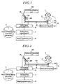
- the surface shape measuring apparatus of the first invention which accomplished the first object, comprises, as shown in FIG. 1, a stereo-photographing unit 90 for photographing an object 1 in stereo; a relative position changing part 4 for changing the positional relation between the stereo-photographing unit 90 and the object 1; a parameter storing part 5 for storing stereo-photographing parameters in a plurality of directions from which the stereo-photographing unit 90 photographs the object 1; a stereo-image generating part 6 for controlling the stereo-photographing unit 90 to photograph the object 1 from the plurality of directions with the stored stereo-photographing parameters and generating stereo images of the object 1; and a surface shape processing part 7 for measuring the surface shape of the object 1 based on the stereo images of the object 1.
- the object 1 is placed in a position to be photographed by the stereo-photographing unit 90, and the positional relation is relatively changed by the relative position changing part 4 so that the object 1 can be photographed from a plurality of directions. Since the object 1 is photographed from a plurality of directions, a wider range of surface shape of the object 1 can be measured than when it is photographed from one direction. Since the stereo-photographing parameters in specified photographing directions are stored in advance, the surface shape can be precisely measured even if the object 1 and the stereo-photographing unit 90 are not positioned precisely.
- the relative position changing part 4 has a stage 2 for changing the position of the stereo-photographing unit 90 or the position of the object 1. It is recommendable that the object 1 is placed in a specified position on the stage 2.
- the relative position changing part 4 is configured to make a relative displacement in the same directions as the plurality of directions with calculated stereo-photographing parameters when the stereo-photographing unit 90 photographs the object 1, the surface shape of the object 1 can be measured precisely using the stereo-photographing parameters.
- the parameter storing part 5 stores stereo-photographing parameters obtained by the steps of placing a calibration subject 11 on which reference points are three-dimensionally arranged in a position where the object 1 is to be placed, setting the relative position changing part 4 so that the stereo-photographing unit 90 is pointed in a direction to photograph the calibration subject 11, photographing the calibration subject 11 with the stereo-photographing unit 90, and calculating the stereo-photographing parameters based on the photographed stereo images of the calibration subject 11. Since the positions of the reference points on the calibration subject 11 are known precisely, the stereo-photographing parameters can be calculated precisely.
- the parameter storing part 5 stores parameters calculated by comparing the position of reference points on the calibration subject 11 stored in advance with positions of reference points calculated based on the stereo images of the reference points on the calibration subject 11 photographed by the stereo-photographing unit 90.
- the stereo-photographing parameters include at least one of the baseline length, photographing position and tilt of the stereo-photographing unit 90 in the direction from which the photographing unit 90 photographs the object 1.
- the stereo-photographing parameters are parameters used to convert a pair of images photographed by the stereo-photographing unit 90 into rectified images. Since the rectified images can be stereoscopically viewed, the unevenness on the surface of the object 1 can be precisely calculated based on the parallax difference between the stereo images.
- the stereo-photographing unit 90 has two imaging devices 9R and 9L attached to an imaging device fixing body 91 in parallel to each other at a specified distance "1" apart from each other.
- stereo-photographing unit 90 Since the stereo-photographing unit 90 has two imaging devices, stereo images of an object can be photographed simultaneously. This is advantageous when the number of objects is large and the work to measure the surface shapes of them is large, or when stereo images cannot be obtained unless they are photographed simultaneously since the object vibrates or moves.
- the surface shape measuring apparatus of the second invention which accomplishes the first object, comprises, as shown in FIG. 17, a stereo-photographing unit 90 for photographing an object 1 in stereo; a relative position changing part 4 for changing the positional relation between the stereo-photographing unit 90 and the object 1; a stereo-photographing direction control part 12 for controlling the relative position changing part 4 so that the stereo-photographing unit 90 can photograph the object 1 from at least three directions to obtain stereo images of primary peripheral surfaces of the object 1; a parameter storing part 5 for storing stereo-photographing parameters in directions which are determined by the stereo-photographing direction control part 12 and from which the stereo-photographing unit 90 photographs the object; a stereo-image generating part 6 for controlling the stereo-photographing unit 90 to photograph the object 1 from the plurality of directions and generating stereo images of the object 1 in the photographing directions; and a surface shape processing part 7 for composing the stereo images of the object 1 in directions determined by the stereo-photographing direction control part 12 and measuring the surface shape of primary peripheral
- the function of measuring the surface shape of the primary peripheral surfaces of the object is accomplished by activating the relative position changing part 4 based on control of the stereo-photographing control part 12 so that the stereo-photographing unit 90 can photograph the object 1 in stereo from at least three directions and obtaining stereo images of the primary peripheral surfaces of the object.
- the stereo-photographing unit 90 can photograph the object 1 in stereo from at least three directions and obtaining stereo images of the primary peripheral surfaces of the object.
- stereo images photographed from one direction only a limited range of the surface shape of the object 1 can be measured.
- the surface shape can be measured over most of the circumference of the object 1.
- the surface shape measuring apparatus of the third invention which accomplishes the first object, comprises, as shown in FIG. 18, an imaging device 10 for photographing an object 1; a relative position changing part 4 for changing the positional relation between the imaging device 10 and the object 1; a stereo-photographing control part 9 for controlling the relative position changing part 4 so that the imaging device 10 can photograph the object 1 from stereo-photographing directions including a pair of right and left photographing directions; a parameter storing part 5 for storing stereo-photographing parameters in a plurality of stereo-directions from which the imaging device 10 photographs the object 1; a stereo image generating part 6 for controlling the imaging device 10 to photograph the object 1 from the plurality of stereo-photographing directions with calculated photographing-parameters and generating stereo images of the object 1; and a surface shape processing part 7 for measuring the surface shape of the object based on the stereo images of the object 1.
- the function of photographing stereo images of an object is accomplished by one imaging device 10 and the stereo-photographing control part 9. Since the number of imaging devices is smaller than that of imaging devices of the stereo-photographing unit 90 in the first invention, the equipment cost can be reduced. This is advantageous when the number of the objects 1 is small.
- the relative position changing part 4 has a stage for changing the position of the imaging device 10 or the position of the object 1. Also, when the relative position changing part 4 is configured to make a relative displacement in the same directions as the plurality of directions with calculated stereo-photographing parameters when the imaging device photographs the object 1, the surface shape of the object 1 can be measured precisely using the stereo-photographing parameters.
- the parameter storing part 5 stores stereo-photographing parameters obtained by the steps of placing a calibration subject 11 on which reference points are three-dimensionally arranged in a position where the object 1 is to be placed, controlling the relative position changing part 4 so that the imaging device 10 can photograph the calibration subject 11 from the right or left photographing directions, photographing the calibration subject 11 with the imaging device 10, and calculating the stereo-photographing parameters of the imaging device 10 based on stereo images of the calibration subject 11 photographed from the right and left photographing directions.
- the parameter storing part 5 stores parameters calculated by comparing the position of reference points on the calibration subject 11 stored in advance with positions of reference points calculated from stereo images of the reference points on the calibration subject 11 photographed from the right and left photographing directions by the imaging device 10.
- the stereo-photographing parameters include at least one of the baseline length between the positions where the imaging device 10 photographs the object 1, the photographing positions of the imaging device 10, and the tilt of the imaging device 10 in the right and left photographing directions.
- the unevenness on the surface of the object 1 can be precisely calculated based on the parallax difference between the stereo images.
- the surface shape measuring apparatus of the fourth invention which accomplishes the first object, comprises, as shown in FIG. 19, an imaging device 10 for photographing an object 1; a relative position changing part 4 for changing the positional relation between the imaging device 10 and the object 1; a stereo-photographing control part 9 for controlling the relative position changing part 4 so that the imaging device 10 can photograph the object 1 from stereo-photographing directions including a pair of right and left photographing directions; a primary peripheral surface photographing direction control part 13 for controlling the stereo-photographing control part 9 so that the imaging device 10 can photograph the object 1 in stereo from at least three directions to obtain stereo images of primary peripheral surfaces of the object 1; a parameter storing part 5 for storing stereo-photographing parameters in stereo-photographing directions from which the imaging device 10 photographs the object 1; a stereo-image generating part 6 for controlling the imaging device 10 to photograph the object 1 from directions determined by the primary peripheral surface photographing direction control part 13 and having calculated stereo-photographing parameters, and generating stereo images of the object 1; and a surface shape processing
- the surface shape measuring apparatuses of the first and second inventions further comprise an orthogonal projection image producing part for producing an orthogonal projection image of the object 1 from stereo images of the object 1 photographed by the stereo-photographing unit 90.
- the surface shape measuring apparatuses of the third and fourth inventions further comprise an orthogonal projection image producing part for producing an orthogonal projection image of the object 1 from stereo images of the object 1 photographed by the stereo-photographing control part 9 and the imaging device. 10.
- the surface shape of the object 1 measured by the surface shape processing part 7 is taken into account.
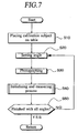
- the surface shape measuring method of the fifth invention which accomplishes the first object, comprises, as shown in FIG. 7 and FIG. 8, the steps of placing a calibration subject 11 on which reference points are three-dimensionally arranged in a position where an object 1 is to be placed (S10) and setting one of the stereo-photographing unit 90 or the calibration subject 11 in a specified direction from which a stereo-photographing unit 90 photographs the calibration subject 11 (S20); photographing the calibration subject 11 with the stereo-photographing unit 90 (S30); and calculating stereo-photographing parameters based on the photographed stereo images of the calibration subject 11 (S40 and S48).
- the calculated stereo-photographing parameters are stored.
- the method further comprises, as shown in FIG. 12 and FIG.
- the surface state plotting apparatus of the seventh invention which accomplishes the second object, has a plotting device 8 for plotting the surface shape of an object 1 based on stereo images of the object 1 measured by the surface shape measuring apparatus of one of the first to forth inventions.
- an artificial intelligence engine suitable to plot the surface shape of the object 1 is used in the plotting.
- the object 1 is a buried cultural property
- the measured surface shape can be appropriately corrected from an archeological point of view to remove scratches and extraneous matters and extract archaeologically valuable information.
- the surface shape measuring apparatus of the eighth invention which accomplishes the first object, comprises as shown in FIG. 20 and FIG. 21, a stereo photographing part 3 having a plurality of stereo-photographing units for photographing a measuring object 1 in stereo; a parameter storing part 5 for storing stereo-photographing parameters in each of the plurality of directions from which the stereo-photographing units photograph the measuring object 1; a stereo image generating part 6 for controlling the stereo-photographing part 3 to photograph the measuring object 1 from the plurality of directions with stored stereo-photographing parameters, and generating stereo images of the measuring object 1; a surface shape processing part 7 for measuring the surface shape of the measuring object 1 based on the stereo images of the measuring object 1.
- the measuring object 1 is placed in a position to be photographed by the stereo-photographing part 3, and at least two stereo-photographing units constituting the stereo-photographing part 3 photographs the measuring object 1 in stereo from a plurality of directions.
- Each of the stereo-photographing units has right and left imaging devices 3R and 3L for photographing the measuring object 1 in stereo. Since the measuring object 1 is photographed in stereo from a plurality of directions, a wider range of surface shape of the object 1 can be measured than when it is photographed from one direction. Since the stereo-photographing parameters in specified photographing directions are stored in advance, the surface shape can be precisely measured even if the object 1 and the stereo-photographing unit 90 are not positioned precisely.
- the stereo-photographing part 3 has at least two stereo-photographing units, the measuring object 1 does not have to be rotated or the stereo-photographing units do not have to be moved and the photographing can be performed quickly when a large area of the peripheral surface of the measuring object 1 must be photographed.
- the surface shape measuring method further comprises, as shown in FIG. 23, the steps of photographing the measuring object 1 in stereo from the at least two' directions with the stored stereo-photographing parameters (S121); generating stereo images of the measuring object 1 from the photographed images using the stereo-photographing parameters (S122); and measuring the surface shape of the measuring object 1 based on the stereo images of the measuring object 1 (S123).
- the surface shape measuring method of the twelfth invention which accomplished the first object, comprises, as shown for example in FIG. 24 and FIG. 26, the steps of placing a calibration subject 11 on which reference points are three-dimensionally arranged in a position where a measuring object is to be placed (S130) ; photographing the calibration subject 11 with at least three imaging devices for photographing from predetermined directions (S131); extracting an overlapping photographic area from images of the calibration subject 11 photographed by two imaging devices of the at least three imaging devices (S132 and S133), and calculating stereo-photographing parameters (S137).
- the stereo-photographing part 3 has stereo-photographing units for each of the stereo-photographing directions.
- Each of the stereo units has at least two imaging devices 3R and 3L attached to in parallel to each other at a specified distance "l" apart from each other and can photograph stereo images of the measuring objects 1 simultaneously. This is advantageous when the number of measuring objects 1 is large and the work to measure the surface shapes of them is large, or when stereo images cannot be obtained unless they are photographed simultaneously since the measuring object 1 vibrates or moves.
- the surface shape measuring apparatuses further comprises an orthogonal projection image producing part for producing an orthogonal projection image of the measuring object 1 from at least either of stereo images of the object 1 photographed by the stereo-photographing part 3 and the image position of the measuring object 1.
- an orthogonal projection image producing part for producing an orthogonal projection image of the measuring object 1 from at least either of stereo images of the object 1 photographed by the stereo-photographing part 3 and the image position of the measuring object 1.
- the surface shape measuring apparatus of the eighteenth invention which accomplish the first object, comprises, as shown in FIG. 43, a single-lens imaging device 10 for photographing a measuring object 1 together with a calibration subject 11E placed in the vicinity of the background of the measuring object 1 and having reference points whose three-dimensional relative positional relation have been determined in advance from a specified direction; a relative position changing part 4 for changing the positional relation between the measuring object 1 and the imaging device 10; a stereo single direction control part 18 for controlling the relative position changing part 4 to change the positional relation between the measuring object 1 and the imaging device 10 so that the imaging device 10 can photograph in stereo from first and second photographing directions; a stereo-photographing control part 17 for controlling the relative position changing part 4 to move at least one of the measuring object 1 and the imaging device 10 and controlling the stereo single direction control part 18 so that the imaging device 10 can photograph the measuring object 1 from a plurality of directions; a photographing parameter calculating part 50 for extracting images of the reference points from image data photographed in stereo by the imaging device 10 and
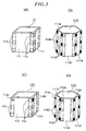
- FIG. 1 is a block diagram illustrating the structure of a first embodiment of this invention.
- a measuring object 1 is an object having a surface shape or surface pattern to be three-dimensionally measured in a non-contact manner such as a trove, human body, vehicle, or machine structure.
- a table 2 is a stand to place the measuring object 1 on, and may be a stage.
- a stereo-photographing unit 90 is a device for photographing the measuring object 1 placed on the table 2 in stereo and comprises two imaging devices 9R and 9L such as CCDs (charged-coupled devices), digital cameras or film-type cameras which are attached to a rod as an imaging device fixing body 91 at a distance 1 apart from each other.
- the two imaging devices 9R and 9L are attached to the imaging device fixing body 91 in such a manner that their optical axes are generally parallel to each other and oriented toward the measuring object 1.
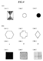
- FIG. 3 is a perspective view illustrating the structures of calibration subjects for use in calculation of stereo-photographing parameters.
- FIG. 3(A) shows a calibration subject having a tubular body with a rectangular cross-section
- FIG. 3 (B) shows a calibration subject having a tubular body with a hexagonal cross-section
- FIG. 3(C) shows another aspect of the calibration subject having a tubular body with a rectangular cross-section
- FIG. 3(D) shows another aspect of the calibration subject having a tubular body with a hexagonal cross-section.
- a calibration subject 11 having a tubular body with a rectangular cross-section has four reference sides 111. On each of the reference sides 111, at least six reference point marks 113 are formed.
- Side reference targets 112 may be directly formed on the reference sides 111 of the calibration subject 11 in addition to the reference point marks 113 so that the reference sides 111 may be distinguished from one another.
- the side reference targets 112 have functions as reference point marks 113 in addition to being used to distinguish the reference sides 111 of the calibration subject 11 from one another.
- five reference point marks 113 and one side reference target 112a or 112b are formed on each reference side 111 as shown in FIG. 3(C).
- a calibration subject 11D having a tubular body with a hexagonal cross-section has six reference sides 111D, on each of which five reference point marks 113D and one side reference target 112c, 112d or 112e are formed as shown in FIG. 3(D).
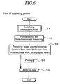
- FIG. 4 is an explanatory diagram of reference point marks and side reference targets formed on a calibration subject.
- FIG. 4 (A) shows examples of the reference point marks and
- FIG. 4(B) shows examples of the side reference targets.
- the reference point marks there may be used a pattern, graphic form or symbol, such as a strike mark (A1), white circle with black outline (A2) or black circle (A3), from which the three-dimensional positions of the reference points can be accurately obtained.
- stereo-photographing is performed for each reference side 111 of the calibration subject 11.
- stereo-photographing is performed the same number of times as the number of the reference sides 111.
- the directions from which stereo-photographing is performed are the directions from which the stereo-photographing unit 90 photographs the reference sides 111 in stereo and are preferably coincident with the directions normal to the reference sides 111.
- the number of the reference sides 111 of the calibration subject 11 is preferably determined based on the number of sides by which the entire circumference of the measuring object 1 is divided.
- the number of the reference sides 111 of the calibration subject 11 has to be large.
- six reference sides 111 are preferably provided on the calibration subject 11 as shown in FIG. 3(B).
- FIG. 7 is a flowchart for explaining the initialization in a direction from which stereo-photographing is performed.
- the calibration subject 11 is placed on the table 2 (S10).
- the relative position changing part 4 sets the angle ⁇ of the table 2 or that of the stereo-photographing unit 90 (S20).
- the angle ⁇ is set to 0° at first.
- stereo-photographing unit 90 photographs one of the reference sides 111 of the calibration subject 11 in stereo (S30). In the case of stereo cameras, the two cameras photograph simultaneously.
- the photographing is performed with a flashbulb.
- an initializing and measuring process necessary for stereo-photographing is executed (S40). This step is repeated until all the reference sides 111 of the calibration subject 11 are photographed and subjected to the initializing and measuring process (S50). This is because the number of the reference sides 111 is the same as the number of directions from which stereo-photographing is performed. For example, when the calibration subject 11 with a rectangular cross-section as shown in FIG. 3(A) is used, photographing is carried out at angles of 0°, 90°, 180° and 270° for the angle ⁇ since there are four reference sides 111. When the calibration subject 11B with a hexagonal cross-section as shown in FIG. 3(B) is used, photographing is carried out at angles of 0°, 60°, 120°, 180°, 240° and 300° for the angle ⁇ since there are six reference sides 111B.
- the flowchart in FIG. 7 shows a case in which the initializing and measuring process is executed for each reference side 111 of the calibration subject 11 in step S40.
- the apparatus may be configured to send the photographed stereo images to the stereo image generating part 6 and the surface shape processing part 7 after photographing all the reference sides 111 and execute the initializing and measuring process on the stereo images by one operation after step S50.
- the apparatus may be configured to execute an initializing and measuring process as shown in FIG. 8 for each of the reference sides 111 after determining the reference sides 111 using the calibration subject 11.
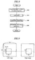
- FIG. 8 is a flowchart for explaining the initializing and measuring process in FIG. 7 in detail.
- the initializing and measuring process is executed on the stereo images for each of the reference sides 111.
- the process is executed on right and left images photographed by the stereo-photographing unit 90 as a pair of stereo images.
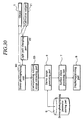
- FIG. 9 is a diagram for explaining the relation between a template image for use in the sequential similarity detection algorithm and a pair of right and left images.
- an image with a size of N1 x N1 is adopted from the left image as a template image to be searched in the right image.
- a search is made for the same image as the N1 ⁇ N1 image in the left image along an identical line in the right image.
- the point where the residual R(a, b) given by the equation (1) is minimum is the position of the desired image.
- FIG. 10 is a graph for explaining the moment method, wherein the vertical axis indicates the measurement value f(x, y) and the horizontal axis indicates the spatial distribution X, Y.
- the vertical axis indicates the measurement value f(x, y)
- the horizontal axis indicates the spatial distribution X, Y.
- points having a measurement value f (x, y) which is greater than a threshold value T are subjected to the equations (2) and (3) below.
- FIG. 10 is shown in one dimensional form for simplicity, the process is two-dimensionally executed in reality.
- the correlation method and moment method have been described as the initializing and measuring process, there are other various methods for obtaining stereo-photographing parameters in a direction from which stereo-photographing is performed. As long as the shape of the reference point marks or the calibration subject can be easily detected, an equivalent method having the same function as the correlation method or moment method may be adopted.
- FIG. 11 is a diagram for explaining the orientation calculation using a model coordinate system XYZ and right and left camera coordinate systems xyz.
- the origin O of the model coordinate system xyz is placed at the left projection center and a line connecting the origin O and the right projection center is designated as the X-axis.
- the baseline length 1 is used as the unit length.
- the parameters to be obtained are the following five rotational angles: the rotational angle ⁇ 1 of the Z-axis and the rotational angle ⁇ 1 of the Y-axis of the left camera, and the rotational angle ⁇ 2 of the Z-axis, the rotational angle ⁇ 2 of the Y-axis and the rotational angle ⁇ 2 of the X-axis of the right camera.
- the rotational angle ⁇ 1 of the X-axis of the left camera is 0 and thus is not needed to be taken into account.
- the coplanar conditional equation (4) becomes the equation (5) and the parameters can be obtained by solving the equation.
- the three-dimensional positions and tilts of the cameras can be obtained in the coordinate system of the calibration subject.
- rectified images which can be viewed stereoscopically can be produced, and three-dimensional measurement by the stereo method can be carried out. Images which can be stereoscopically viewed are images without vertical parallax which are parallel and normal to an object.
- the thus obtained stereo-photographing parameters are stored for all the angles ⁇ representing each of the reference sides 111 (S48).
- the initialization of the coordinate system in step S1 is thereby completed.
- the process may be executed prior to each measurement or can be executed once when the coordinate systems do not include errors due to changes over time.
- a motor is used as the rotary driving part 41 and sequentially controlled so that the angle ⁇ between the table 2 on which the calibration subject 11 is placed and the stereo-photographing unit 90 coincides with the photographing angle ⁇ for the reference side 111 to be measured
- the entire process can be executed automatically when the calibration subject 11 is placed on the table 2.
- An operator may manually adjust the table 2 on which the calibration subject 11 is placed so that the angle of the table 2 coincides with the photographing angle ⁇ prior to photographing and processing.
- FIG. 12 is a flowchart for explaining the process for photographing a measuring obj ect in stereo.
- a measuring object 1 is placed on the table 2 (S60).
- the relative position changing part 4 sets an angle ⁇ corresponding to a direction from which the measuring object 1 is to be photographed by the stereo-photographing unit 90 (S70). For example, the angle is set to 0° at first.
- the stereo-photographing unit 90 photographs the measuring object 1 (S80). In the case of stereo cameras, the cameras photograph the measuring object 1 simultaneously.
- the relative position changing part 4 sets another angle ⁇ corresponding to another direction from which the measuring object 1 is to be photographed by the stereo-photographing unit 90 (S70).
- the measuring object 1 is photographed at angles of 0°, 90°, 180° and 270°.
- the photographing must be carried out at angles of 0°, 60°, 120°, 180°, 240° and 300°.
- FIG. 15 is a diagram for explaining the principle of the stereo method.
- two identical cameras are placed with their optical axes parallel to each other and with the principal points of their lenses at an equal distance "a" from a CCD plane on which images 1 and 2 are focused, and the CCD is placed at a right angle to the optical axes.
- the distance between the two optical axes (baseline length) is assumed to be 1.
- the data are also used as initial values for the automatic measurement.
- the data obtained here can be used without executing the process in step S103.
- the process in step S103 is not executed, the images which will be produced by the displaying/plotting part 8 are less accurate than when the process in step S103 is executed.
- stereo matching automatic measurement
- area-based matching using the normalized correlation process is used.
- the information is also used. A large number of three-dimensional coordinates on the surface of the object can be thereby obtained.
- FIG. 16 is a diagram for explaining the difference between a central projection image and an orthogonal projection image.
- An image taken using a lens is a central projection image and is distorted since the subject is captured at the principal point of the lens.
- an orthogonal projection image is an image obtained by projecting a subject in parallel with a lens located at an infinite distance from the subject.
- the precise dimension of the subject is expressed in the image as in a map.
- a drawing of the measuring object 1 can be easily produced by tracing the orthogonal projection image.
- time and labor can be significantly saved and the dimensional accuracy of the image can be improved because of the orthogonal projection image.
- any person can easily produce a drawing with high accuracy.
- the stereo image storing part 15 stores a pair of stereo images of the measuring object 1 photographed by the stereo-photographing unit 90, preferably together with the photographing angle ⁇ .
- the stereo image storing part 15 preferably stores the generated orthogonal projection image of the measuring object 1 together with the stereo images.
- FIG. 18 is a block diagram illustrating the structure of a third embodiment of this invention.
- the third embodiment differs from the first embodiment in that the function of photographing an object in stereo is accomplished by one imaging device 10 and a stereo-photographing control part 9.
- the stereo-photographing control part 9 rotates an imaging device connecting rod 46 as the relative position changing part 4 so that the imaging device 10 can photograph the measuring object 1 from stereo-photographing directions consisting of a pair of right and left photographing directions.
- the imaging device connecting rod 46 keeps the distance d between the table 2 and the imaging device 10 constant and is driven by the rotary driving part 41 to move the imaging device 10 by a rotational angle difference ⁇ .
- the distance from the original position of the imaging device 10 to the position a rotational angle difference ⁇ away from the original position is the baseline length "1", and the positions correspond to the right and left photographing directions.
- the images of the measuring object 1 photographed by the imaging device 10 are preferably stored in a monaural image storing part 16 together with the photographing angle ⁇ .
- each stereo pair images are obtained by converging photographing, in other words, the photographed images are perpendicular to the object and are not parallel to each other.
- the imaged area and its scale in the right and left images are less stable as compared with the images photographed by the stereo-photographing unit 90 of the first or second embodiment.
- the possibility that the measurement accuracy is unstable or the automatic measurement (stereo matching) does not succeed is higher as compared with the stereo-photographing unit 90 of the first or second embodiment.
- FIG. 19 is a block diagram illustrating the structure of a fourth embodiment of this invention.
- the fourth embodiment differs from the third embodiment in that a primary peripheral surface photographing direction control part 13 and a stereo image storing part 15 are provided.
- the primary peripheral surface photographing direction control part 13 controls the stereo-photographing control part 9 so that the measuring object 1 can be photographed from at least three directions to obtain stereo images of the primary peripheral surfaces of the measuring object 1.
- To photograph from three directions means to obtain stereo images consisting of a pair of right and left images from three angles.
- the primary peripheral surface photographing direction control part 13 allows the measurement of a large number of measuring objects 1 to be made with high efficiency.
- the primary peripheral surface photographing direction control part 13 may be a sequence program registered in a PLC which controls the rotary driving part 41, the stereo-photographing control part 9 and the imaging device 10 in an interlocking manner.
- a stereo-photographing part 3 photographs the measuring object 1 or the calibration subject 11 placed on the table 2 in stereo and has, for example, four sets of stereo-photographing units for each stereo-photographing direction.
- Each stereo-photographing unit comprises two imaging devices 3R and 3L such as CCDs (charged-coupled devices), digital cameras or film-type cameras which are attached to a rod (not shown) as an imaging device fixing body at a distance 1 apart from each other.
- the optical axes of the two imaging devices 3R and 3L are generally parallel to each other and oriented toward the measuring object 1.
- the two imaging devices 3R and 3L are located generally at the same distance d from the measuring object 1.
- camera calibration is executed on the imaging devices 3R and 3L as the stereo-photographing unit. To execute camera calibration is to obtain the focal length, principle point position and distortion aberration of the camera with high precision.
- Fig. 21 is a block diagram illustrating the structure of an essential part of a fifth embodiment of this invention, showing the function of processing the signals of images photographed in stereo by the stereo-photographing part.
- the stereo-photographing parameter storing part 5 stores stereo-photographing parameters in a plurality of directions from which the stereo-photographing part 3 photographs the measuring object 1 in stereo.
- the photographing parameters are used to rectify a pair of right and left images photographed in stereo to convert them to stereo images which can be viewed stereoscopically.
- the parameters are the baseline length, photographing position and tilt of each stereo-photographing unit.
- a stereo image generating part 6 generates stereo images of the measuring object 1 after the stereo-photographing part 3 photographs the measuring object 1 from the plurality of directions with the stored stereo-photographing parameters, and comprises a processor which can perform high-speed image processing.
- a surface shape processing part 7 measures the surface shape of the measuring object 1 based on the stereo images of the measuring object 1.
- a displaying/plotting part 8 comprises a display device such as a CRT and liquid crystal display for displaying the surface shape of the measuring object 1 measured by the surface shape processing part 7, a plotter or printer for producing graphics on a sheet of paper, a digital plotter for producing three-dimensional impression data, or the like.
- the calibration subject 11 is used to determine a coordinate system used as a reference to produce rectified stereo images and to obtain the positions and tilts of the two imaging devices 3R and 3L constituting the stereo-photographing part 3. To improve the accuracy in producing rectified stereo images, the calibration subject 11 is preferably slightly larger than the measuring object 1.
- FIG. 22 is a flowchart for explaining the initialization in a direction in which stereo-photographing is performed.
- the calibration subject 11 on which reference points are three-dimensionally arranged is placed on the position where the measuring object 1 is to be placed (S110).
- the stereo-photographing unit photographs the calibration subject 11 in stereo from at least two directions (S111).
- initializing and measuring process is executed on the stereo images for each reference side 111.
- the process is executed on the two right and left images photographed by the stereo-photographing unit 3 as one stereo pair.
- the thus obtained stereo-photographing parameters are stored for all the stereo-photographing directions representing each of the corresponding reference sides 111 or for all pairs of the imaging devices 3R and 3L (S125).
- the initialization of the coordinate system in step S1 is thereby completed.
- the process may be executed prior to each measurement or can be executed once when the coordinate systems do not include errors due to changes over time.
- FIG. 23 is a flowchart for explaining the process for photographing the measuring object in stereo.
- the measuring object 1 is placed on the table 2 (S120).
- the stereo-photographing unit photographs the measuring object 1 in stereo from at least two directions with stored stereo-photographing parameters (S121).
- the surface shape processing part 7 executes the measuring process (S122).
- the images photographed in stereo are formed into stereo images of the measuring object 1 using the stereo-photographing parameters.
- the actual stereo images of the measuring object 1 are reconstructed into rectified images which can be viewed stereoscopically.
- the reconstruction process into rectified images is not necessary when the stereo cameras are attached parallel to each other without vertical parallax and do not move over time. However, when the reconstruction process into rectified images is executed, the stereo cameras need not be positioned precisely or changes over time do not have to be taken into account.
- the contour and characteristic points of the measuring object 1 in each photographing direction are measured (S123).
- the measurement of the contour and characteristic points of the measuring object 1 is made by designating the corresponding points on the right and left images with a mouse or the like, referring to stereo images displayed on the displaying/plotting part 8.
- the three-dimensional coordinates of the positions can be obtained from the principle of the stereo method since rectified images parallel to the measuring object have been obtained based on the stereo-photographing parameters of the images.
- the automatic measurement area in step S124 is set.
- the automatic measurement area may be automatically set using the information on the distance to the object or image processing such as characteristic point extracting process.
- stereo matching automatic measurement
- area-based matching using the normalized correlation process is used.
- the information is also used. A large number of three-dimensional coordinates on the surface of the object can be thereby obtained.
- FIG. 24 is a perspective view of an essential part of a sixth embodiment
- FIG. 25 is a block diagram illustrating the structure of an essential part of the sixth embodiment.
- the sixth embodiment differs from the fifth embodiment in that an imaging device group 20 and a stereo-photographing area extracting part 21 are provided instead of the stereo-photographing part 3 comprising stereo-photographing units for each stereo-photographing direction.
- the imaging device group 20 comprises eight imaging devices 10A, 10b, ..., and 10H, each of which photographs the measuring obj ect 1 from a predetermined direction.
- the imaging devices 10A to 10H have photographing angles ⁇ A to ⁇ H, respectively, determined with respect to a reference azimuth such as the north direction N and located at distances dA to dH, respectively, from the measuring object 1 or the calibration subject 11.
- the optical axes of the imaging devices 10A to 10H are directed to the measuring object 1 or the calibration subject 11 although the optical axes of the imaging devices 3R and 3L (see FIG. 20) constituting a stereo-photographing unit are generally parallel to each other and oriented toward the measuring object 1 in the fifth embodiment.
- the stereo-photographing area extracting part 21 extracts an overlapping area from images of the measuring object 1 photographed by two imaging devices of the imaging device group 20.
- the overlapping area is useful to produce stereo images.
- the stereo-photographing parameter storing part 5 stores parameters in the photographing directions of at least two pairs of imaging devices of the imaging device group 20 which have photographed the images having an overlapping area extracted by the stereo-photographing area extracting part 21.
- the detection of the targets' positions of the center of gravity (S134), association (S135), orientation calculation (S136), and calculation of stereo-photographing parameters (S137) are the same as those in steps S42, S44, S46 and S48, respectively, in FIG. 8.
- the calculated stereo-photographing parameters are stored in the stereo-photographing parameter storing part 5 (S137). Then, it is judged whether there are other two imaging devices constituting another pair of stereo-photographing devices (S138). If so, the process returns to step S133. Otherwise, the measurement of the calibration subject 11 is completed.
- FIG. 27 is a flowchart for explaining the process for photographing the measuring object in stereo in the sixth embodiment.
- the measuring object 1 is placed in a position such as on the table 2 (S140).
- the imaging devices 10A, 10B, ..., and 10H of the imaging device group 20 photograph the measuring object 1 in the position (S141).
- a pair of imaging devices constituting a pair of stereo-photographing devices are extracted (S142).
- the stereo-photographing image extracting part 21 extracts an overlapping area from the images photographed by the two imaging devices constituting the paired stereo-photographing devices (S143).
- the stereo-photographing parameters of the paired stereo-photographing devices stored in the stereo-photographing parameter storing part 5 the images of the overlapping area extracted in step S143 are formed into stereo images of the measuring object 1 (S144).
- the production of rectified images (S144), the measurement of the contour and characteristic points of the measuring object (S145), and the automatic measurement (S146) are the same as those in steps S122 to S124, respectively, in FIG. 23.
- the measurement of the contour and characteristic points of the measuring object (S145) and the automatic measurement (S146) correspond to the process for measuring the surface shape of the measuring object 1 based on the stereo images of the measuring object 1. Then, it is judged whether there are other two imaging devices constituting another pair of stereo-photographing devices (S147). If so, the process returns to step S143. Otherwise, the measurement of the measuring object 1 is completed.
- FIG. 28 is a diagram illustrating the structure of an essential part of a seventh invention of this invention.
- the stereo-photographing unit 90 comprises right and left imaging devices 9R and 9L for photographing the measuring object 1 in stereo directly from first photographing directions.
- Second photographing directions are formed by light paths reflected from mirrors 22R and 22L as a light path changing part 22 so that the stereo-photographing unit 90 can photograph the measuring object 1 in stereo from the second photographing directions.
- FIG. 29 is an explanatory diagram of the measuring object captured by each imaging device of the stereo-photographing unit.
- the right imaging device 9R or the left imaging device 9L captures a real image of the measuring object 1 and an image of the measuring object 1 viewed from a different angle which is reflected from the mirror 22R or 22L.
- the real images of the measuring object 1 are images photographed in stereo directly from the first photographing directions.
- the mirror images of the measuring object 1 are images photographed in stereo from the second photographing directions using the light path changing part 22.
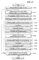
- FIG. 30 is a block diagram illustrating the structure of an essential part of the seventh embodiment of this invention.
- the stereo-photographing unit 90 comprises a pair of imaging devices 9R and 9L such as CCDs, digital cameras or film-type cameras.
- the light path changing part 22 changes the light paths between the stereo-photographing unit 90 and the measuring object 1 so that the stereo-photographing unit 90 can photograph the measuring object 1 in stereo from the second photographing directions.
- mirrors for example, are used.
- a corresponding subject image extracting part 25 separates a real image and a mirror image in an image photographed by the stereo-photographing unit 90.
- the corresponding subject image extracting part 25 separates an image photographed from the first photographing direction and an image photographed from the second photographing direction based on, for example, the size of the images.
- the stereo-photographing parameter storing part 5 which stores stereo-photographing parameters in a plurality of directions from which the stereo-photographing unit 90 photographs the measuring object 1, stores stereo-photographing parameters obtained using the calibration subject 11 for paired real images or mirror images in right and left images photographed in stereo.
- the real images and mirror images are photographed at different distances, so that the parameters such as the scale are different for each stereo pair.
- the parameters can be corrected completely by stereo-photographing parameters measured using the calibration subject 11 in initialization (described later).
- the stereo image generating part 6 executes a process for obtaining rectified images from the paired real images or mirror images in the right and left images photographed in stereo using the stereo-photographing parameters.
- the images photographed in stereo only need to have necessary accuracy or resolution regarding the measuring object 1. Namely, in measuring the measuring object 1 three-dimensionally, since the coordinates obtained regarding the measuring object 1 are converted into coordinates on the calibration subject 11, the difference in the photographing distance does not make a large difference. However, the magnification difference between the paired real images and that between the paired mirror images must be within the magnification difference between the real images and mirror images since the smaller magnification difference between the paired real images and the smaller magnification difference between the paired mirror images are more preferable.
- the other component elements are the same as those which have already been described.
- FIG. 31 is a flowchart for explaining the initialization in the seventh embodiment.
- the calibration subject 11 on which reference points are three-dimensionally arranged is placed in a position where the measuring object 1 is to be placed (S150).
- the direction from which the calibration subject 11 is to be photographed by the imaging devices 9R and 9L constituting the stereo-photographing unit 90 is determined (S151).
- the stereo-photographing unit 90 photographs the calibration subject 11 in stereo (S152).
- the corresponding subject image extracting part 25 extracts real images of the calibration subject 11 (first photographing direction) from the images photographed in stereo (S153). For example, when two images having shapes similar to each other but different in size are captured in the images photographed in stereo, the corresponding subject image extracting part 25 regards the lager image as the real image of the calibration subject 11.
- the detection of the targets' positions of the center of gravity (S154), association (S155), orientation calculation (S156), and calculation of stereo-photographing parameters (S157) are the same as those in steps S42, S44, S46 and S48, respectively, in FIG. 8. Then, the corresponding subject image extracting part 25 extracts mirror images of the calibration subject 11 (second photographing directions) from the images photographed in stereo.
- the corresponding subject image extracting part 25 regards the smaller image as the mirror image of the calibration subject 11.
- the detection of the targets' positions of the center of gravity (S159), association (S160), orientation calculation (S161), and calculation of stereo-photographing parameters (S162) are the same as those in steps S42, S44, S46 and S48, respectively, in FIG. 8. Then, it is judged whether there is another direction from which stereo-photographing must be performed (S163). If yes, the process returns to step S151. If no, the measurement of the calibration subject 11 is completed.
- FIG. 32 is a flowchart for explaining the process for photographing the measuring object in stereo in the seventh embodiment.
- the measuring object 1 is placed in a position such as on the table 2 (S170).
- the direction from which the measuring object 1 placed in the position is to be photographed by the imaging devices 9R and 9L constituting the stereo-photographing unit 90 is determined (S171).
- the stereo-photographing unit 90 photographs the measuring object 1 in stereo (S172).
- the corresponding subject image extracting part 25 extracts real images of the measuring object 1 (first photographing direction) from the images photographed in stereo (S173).
- the production of rectified images (S174), the measurement of the contour and characteristic points of the measuring object (S175), and the automatic measurement (S176) are the same as those in steps S122 to S124, respectively, in FIG. 23.
- the measurement of the contour and characteristic points of the measuring object (S175) and the automatic measurement (S176) correspond to the process of measuring the surface shape of the measuring object 1 based on the stereo images of the measuring object 1.
- the corresponding subject image extracting part 25 extracts mirror images of the measuring object 1 (second photographing directions) from the images photographed in stereo (S177).
- the front and back faces of the measuring object 1 can be photographed in stereo simultaneously.
- the number of times the measuring object 1 is rotated to photograph the entire circumference of the measuring object 1 can be reduced. Namely, the measuring object 1 is rotated only half the times it has to be rotated in the case where only the real images are photographed.
- the stereo-photographing unit 90 is used in the above embodiment, the stereo-photographing is made with one imaging device 10 and stereo-photographing control part 24.
- a real image and a mirror image are included in a single image photographed in stereo.
- large images including only the real image or mirror image are required even if the number of photographs increases.
- light-shielding devices such as liquid crystal shutters may be inserted in the first and second photographing directions and images photographed in stereo may be obtained with the light-shielding devices activated.
- a stereo-photographing part 3 photographs the measuring object 1 and the calibration subject 120 placed on the table 2 in stereo and has stereo-photographing units for each stereo-photographing direction.
- Each of the stereo-photographing unit comprises two imaging devices 3R and 3L such as CCDs (charged-coupled devices), digital cameras or film-type cameras which are attached to a rod as an imaging device fixing body (not shown) at a distance 1 apart from each other.
- a surface shape measuring part 60 obtains the surface shape of the measuring object 1 based on the photographing parameters obtained in the photographing parameter calculating part 50 and the positions of images of the measuring object 1 photographed together with the images of the reference points of the calibration subject 120 in the photographed image data from which the photographing parameters have been obtained.
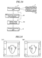
- FIG. 35 is an explanatory diagram of a pair of images of the measuring object and the calibration subject photographed in stereo.
- FIG. 35(A) is an image photographed from the left photographing direction
- FIG. 35 (B) is an image photographed from the right photographing direction.
- the photographing parameters obtained based on the calibration subject 120 are applicable to the image of the measuring object 1.
- the measurement of the surface shape of the measuring object 1 in the surface shape measuring part 60 uses an operation method for measuring unevenness of a surface based on stereo images for use in aerial photogrammetry or the like. It is preferred that the surface shape measuring part 60 extract the characteristic points of the measuring object 1, obtain the positions of the characteristic points, and then measure the entire surface shape of the measuring object 1 based on the thus obtained positions of the characteristic points.
- a displaying/plotting part 8 comprises a display device such as a CRT and liquid crystal display for displaying the surface shape of the measuring object 1 measured by the surface shape measuring part 60, a plotter or printer for producing graphics on a sheet of paper, a digital plotter for producing three-dimensional impression data, or the like.
- the photographing parameter calculating part 50, the surface shape measuring part 60 and the displaying/plotting part 8 may be incorporated in a digital plotter or a personal computer.
- FIG. 36 is a perspective view illustrating the structure of calibration subjects for use in calculation of photographing parameters.
- FIG. 36(A) shows a calibration subject having a frame body with a rectangular cross-section
- FIG. 36(B) shows a calibration subject having a frame body with a hexagonal cross-section
- FIG. 36(C) shows another aspect of the calibration subject having a frame body with a rectangular cross-section
- FIG. 36(D) shows another aspect of the calibration subject having a frame body with a hexagonal cross-section.
- the calibration subject has a frame body so that it does not hide the surface of the measuring object 1 in photographing, measuring and plotting the measuring object 1 from each photographing direction.
- the calibration subject 120 is used to determine a coordinate system as a reference in rectifying images into stereo images and to obtain the positions and tilts of the two imaging devices 3R and 3L constituting the stereo-photographing part 3. To improve the accuracy in the rectification, the calibration subject 120 is preferably slightly larger than the measuring object 1.
- a calibration subject 120 having a frame body with a rectangular cross-section has four reference sides 121.
- at least six reference point marks 123 are formed along the frames. This is because at least six known points are necessary to determine the attitude or coordinates of one plane.
- the reference point marks 123 may be a white mark on a black background or a black mark on a white background reflective mark, or a reflective mark such as a retroreflective target.
- the reference point marks 123 may be formed by attaching stickers on which the reference point marks 123 are printed or by directly printing the reference point marks 123 on the reference sides 121.
- a calibration subject 120B having a frame body with a hexagonal cross-section has six reference sides 121B. At least six reference point marks 123B are formed on each of the reference sides 121B, by which information necessary to determine the attitude or coordinates of one plane is provided. The positions of the reference point marks 123 on the calibration subject 120 must be measured using a three-dimensional coordinate system with a precise instrument in advance.
- stereo-photographing is performed for each reference side 121 of the calibration subject 120.
- stereo-photographing is performed the same number of times as the number of the reference sides 121.
- the directions from which stereo-photographing is performed are the directions from which the stereo-photographing part 3 photographs the reference sides 111 in stereo and, preferably, coincident with the directions normal to the reference sides 121.
- FIG. 37 is a flowchart for generally explaining the entire process for measuring the measuring object with the device shown in FIG. 33 and FIG. 34.
- the measuring object 1 and the calibration subject 120 are placed on the table 2 (S201). The position is so determined that the measuring object 1 is not hidden behind the calibration subject 120.
- an operator photographs the reference sides 121 of the calibration subject 120 in stereo with the stereo-photographing part 3 (S202). Since the stereo-photographing is performed for each reference side 121, eight monaural images are taken in total by the imaging devices 3R and 3L in the case of the frame body with a rectangular cross-section as shown in FIG. 36(A). In the case of the frame body with a hexagonal cross-section as shown in FIG. 36(B), twelve monaural images are taken in total by the imaging devices 3R and 3L.
- the photographing parameter calculating part 50 and the surface shape measuring part 60 read all the photographed images as photographed image data (S210).
- the thus read photographed image data are associated with the reference sides 121 of the calibration subject 120 (S220).
- the process in step S220 is not necessary.
- the operator manually determines a stereo pair images on the displaying/plotting part 8. At this time, the characteristics of the side reference targets 122 such as the shape, pattern or color are useful.
- the process in step S220 is suitable to be executed automatically by image processing.
- image processing is used to distinguish the side reference targets 122 on the side reference sides 121.
- the images of the side reference targets on the reference sides 121 as template images are used to distinguish the marks by image correlation processing.
- the sequential similarity detection algorithm (SSDA) or normalized correlation method may be used.
- the marks can be distinguished more reliably by the normalized correlation processing.
- the distinction of the side reference targets 122 may be made by a method of extracting characteristics or another pattern recognition method instead of by image correlation processing.
- stereo pairs of each reference side 121 are determined (S230).
- the operator determines the stereo pairs referring to the displaying/plotting part 8, possible errors which may occur when a pattern recognition method is mechanically applied can be avoided.
- the right and left images can be easily distinguished when photographing order is fixed to be from left to right, for example.
- the positions of the center of gravity of the side reference targets 122 and the reference point marks 123 are detected in a pair of stereo images of one reference side 121 (S240).
- the side reference targets 122 and the reference point marks 123 are also referred to simply as "targets".
- the positions of the reference point marks are detected roughly by, for example, a correlation method and the positions of the center of gravity of the reference point marks are then precisely calculated. The precise positions could be detected in one step. In that case, however, the operation takes a long time. It is thus preferred to use the sequential similarity detection algorithm as the process for detecting the rough positions.
- the reference point marks in the two images whose centers of gravity have been detected are associated with the reference point marks whose coordinates have been precisely measured in advance (S250).
- the six points on the reference side 121 are associated with the corresponding points. Since the positions of the reference point marks are known in advance, it can be predicted where the reference point marks are positioned in the images. When the reference point marks are different from the other reference point marks, the association can be executed more reliably.
- orientation calculation is executed to obtain the photographing parameters of the imaging devices 3R and 3L, such as the three-dimensional positions and tilts, the distance between the cameras (baseline length: 1) and so on based on the coordinate system of the calibration subject 120 (S260). Then, the actual images of the measuring object 1 are reconstructed into rectified stereo images which can be stereoscopically viewed based on the thus obtained photographing parameters (S270).
- the contour and characteristic points on each measuring surface of the measuring object 1 are measured (S280).
- the measuring surfaces of the measuring object 1 have a close relation with the reference sides 121 of the calibration subject 120.
- the measurement of the contour and characteristic points of the measuring object 1 is executed by designating corresponding points on the right and left images with a mouse or the like, referring to stereo images displayed on the displaying/plotting part 8.
- the three-dimensional coordinates of the positions can be determined from the principle of the stereo method since rectified images parallel to the measuring object 1 have been obtained based on the photographing parameters of the images.
- the automatic measurement area in step S290 is set.
- the automatic measurement area may be automatically set using the information on the distance to the measuring object 1 or image processing such as characteristic point extracting process.
- the data are also used as initial values for the automatic measurement.
- the data obtained in step S280 can be used without executing the process in step S290.
- precise image accomplishments cannot be produced.
- step S290 automatic measurement (stereo matching) is executed (S290).
- area-based matching using the normalized correlation process is used.
- the information is also used.
- a large number of three-dimensional coordinates on the surface of the object can be thereby obtained.
- the three-dimensional coordinates of the positions are calculated by the equations (8), (9) and (10).
- image accomplishments can be created. Since the image accomplishments are created based on three-dimensional coordinate values, as the number of coordinate values is larger, the image accomplishments can be more accurate.
- the coordinate system on each measuring surface is the coordinate system of the calibration subject 11, so that a complete circumferential image of the measuring object 1 can be produced only by connecting the images of the measuring surfaces of the measuring object 1.
- FIG. 39 is a diagram illustrating the structure of an essential part of a ninth embodiment of this invention, showing the positional relation among the measuring object, calibration subject and stereo-photographing part.
- the stereo-photographing part 3 has stereo-photographing units for each stereo-photographing direction, and each of the photographing units comprises a pair of imaging devices 3R and 3L.
- the stereo-photographing part 3 comprises independently arranged imaging devices 10A, 10B, ... and 10H. Since a frame body with a rectangular cross-section is used as the calibration subject 120, eight imaging devices are arranged as the stereo-photographing part 3 so that four stereo-photographing directions can be obtained.
- Each of the imaging devices 10A, 10B, ... and 10H are arranged at angles of ⁇ A, ⁇ B, ... and ⁇ H, respectively, in the clockwise direction with respect to a reference azimuth (such as the direction N of the polar star) and at distances dA, dB, ... and dH, respectively, from the measuring object 1.
- a reference azimuth such as the direction N of the polar star
- Each of the imaging devices 10A, 10B, ... and 10H photographs the measuring object 1 and the calibration subject 120 simultaneously and overlapping areas photographed by adjacent imaging devices are dealt with as image data photographed in stereo in the photographing parameter calculating part 50 and the surface shape state measuring part 60.
- the surface shape of the measuring object 1 can be obtained through a process similar to that in the eighth embodiment using the function of processing signals of images photographed in stereo by the stereo-photographing part shown in FIG. 34.
- FIG. 40 is a block diagram illustrating the structure of a tenth embodiment of this invention.
- the eighth embodiment has a stereo-photographing part 3 provided with a plurality of sets of stereo-photographing units each comprising imaging devices 3R and 3L which can simultaneously photograph the measuring object 1 and the calibration subject 11E from each stereo-photographing direction.
- the ninth embodiment has a stereo-photographing part 3 provided with imaging devices 10A, 10B, ... and 10H which can simultaneously photograph the measuring object 1 and the calibration subject 120 from each photographing direction.
- imaging devices 10A, 10B, ... and 10H which can simultaneously photograph the measuring object 1 and the calibration subject 120 from each photographing direction.
- the tenth embodiment is an apparatus having a pair of stereo-photographing unit which can photograph from every stereo-photographing direction.
- the relative position changing part 4 has a function of rotating the table 2 in a direction ⁇ and comprises a rotary driving part 41 such as a motor, a table rotating shaft 42 for rotating the table 2 by the driving force of the rotary driving part 41, and a stereo-photographing part connecting rod 43.
- the stereo-photographing part connecting rod 43 keeps the distance d between the table 2 and the stereo-photographing unit 90 constant and supports the two imaging devices 9R and 9L in positions oriented toward the table 2.
- the rotary driving part 41 may be a handle or grip which can be rotated by an operator since it can only generate a driving force to position the table 2 with an accuracy of a few degrees.
- the stereo-photographing unit 90 comprises two imaging devices 9R and 9L such as CCDs, digital cameras or film-type cameras which are attached to a rod 91 as an imaging device fixing body at a distance 1 apart from each other.
- the optical axes of the imaging devices 9R and 9L are generally parallel to each other and oriented toward the measuring object 1.
- the direction ⁇ from which the stereo-photographing unit 90 photographs the measuring object 1 is sent to the photographing parameter calculating part 50 and the surface shape measuring part 60 as a measurement signal from a rotational angle sensor attached to the table rotating shaft 42 or is tied to data of images photographed in stereo as photographing angle information.
- the calibration subject 11E may be the calibration subject 120 shown in FIG. 36 or a three-dimensional calibration subject 11E having three-dimensional reference point marks 113E displaced concavely or convexly with respect to the reference sides.
- the three-dimensional calibration subject 11E has a front face as a single reference face on which at least six three-dimensional reference point marks 113E are provided.
- a stereo-photographing control part 17, which rotates the table 2 on which the measuring object 1 is placed with the rotary driving part 41 so that the stereo-photographing unit 90 as the stereo-photographing part 3 can photograph the measuring object 1 from a plurality of directions, comprises a sequence program loaded in a PLC (programmable logic controller).
- PLC programmable logic controller
- FIG. 41 is a block diagram illustrating the structure of a modification of the relative position changing part in the tenth embodiment.
- the relative position changing part 4 comprises a rotary driving part 41, a supporting shaft 44 of the table 2, and a stereo-photographing part rotating shaft 45.
- the stereo-photographing part rotating shaft 45 keeps the distance d between the table 2 and the stereo-photographing unit 90 constant and supports the two imaging devices 9R and 9L attached to an imaging device fitting body 91 in positions oriented toward the table 2.
- the stereo-photographing control part 17 rotates the stereo-photographing part rotating shaft 45 about the supporting shaft 44 of the table 2 with the rotary driving part 41 to move the stereo-photographing unit 90 so that the stereo-photographing unit 90 can photograph the measuring object 1 from a plurality of directions.
- step S202 when the stereo-photographing unit 90 photographs each measuring surface of the measuring object 1 in stereo, the table 2 or the stereo-photographing unit 90 is rotated so that the stereo-photographing unit 90 can be oriented to every measuring surface of the measuring object 1.
- the rotational angles ⁇ of the table 2 or stereo-photographing unit 90 are determined depending upon the number of surfaces to be measured of the measuring object 1 and manually or automatically set.
- the other processes are the same as those in the eighth embodiment.
- FIG. 42 is a block diagram illustrating the structure of an eleventh embodiment of this invention.
- the measuring object 1 is placed on the table 2 together with the calibration subject 11E.
- the measuring object 1 may be hidden behind the calibration subject 11E or the calibration subject 11E must be moved every time the photographing direction is changed.
- the relative position changing part 4 comprises a rotary driving part 41, a table rotating shaft 42 and a stereo-photographing part-calibrator connecting rod 47.
- the stereo-photographing part-calibrator connecting rod 47 keeps constant the distance d between the table 2 and the stereo-photographing unit 90 and the distance d1 between the table 2 and the three-dimensional calibration subject 11E, and supports the two imaging devices 9R and 9L attached to the imaging device fixing body 91 in attitudes oriented toward the table 2.
- the stereo-photographing control part 17 rotates the table 2 on which the measuring object 1 is placed with the rotary driving part 41 so that the stereo-photographing unit 90 as the stereo-photographing part 3 can photograph the measuring object 1 from a plurality of directions.
- the front face of the three-dimensional calibration subject 11E is always included as the background of the measuring object 1 in an image photographed by the stereo-photographing unit 90.
- the front face of the three-dimensional calibration subject 11E is always included in an image photographed by the stereo-photographing unit 90 from whichever direction the measuring object 1 is photographed.
- the three-dimensional reference point marks 113E are provided on a single reference face of the three-dimensional calibration subject 11E, when the relative position changing part 4 rotates the table 2 on which the measuring object 1 is placed in the direction ⁇ , the three-dimensional reference point marks 113E could be considered to be virtually arranged to surround the measuring object 1.
- the stereo-photographing control part 17 rotates the table 2 by 0°, 90°, 180°, and 270°, for example, so that the measuring object 1 can be photographed from four directions
- the three-dimensional calibration subject 11E included in the images photographed by the stereo-photographing unit 90 is substantially equivalent to the calibration subject 120 having a frame body with a rectangular cross-section as shown in FIG. 36(A).
- the stereo-photographing control part 17 rotates the table 2 by 0°, 60°, 120°, 180°, 240° and 300°, for example, so that the measuring object 1 can be photographed from six directions
- the three-dimensional calibration subject 11E included in the images photographed by the stereo-photographing unit 90 is substantially equivalent to the calibration subject 120 having a frame body with a rectangular cross-section as shown in FIG. 36(B).
- FIG. 43 is a block diagram illustrating the structure of a twelfth embodiment of this invention.
- the function of the stereo-photographic unit 90 in the eleventh embodiment is accomplished by a single-lens imaging device 10 and a stereo single direction control part 18.
- the stereo single direction control part 18 controls the rotary driving part 41 of the relative position changing part 4 to rotate the table 2 in order to change the positional relation between the measuring object 1 and the imaging device 10 so that the imaging device 10 can perform stereo-photographing from first and second photographing directions.
- the stereo-photographing control part 17 controls the stereo single direction control part 18 to control the photographing direction of the imaging device 10 so that the imaging device 10 can photograph the measuring object in stereo from a plurality of directions.
- FIG. 44 is a plan view illustrating another example of the calibration subject for use in the tenth to twelfth embodiments.
- the calibration subject 11E for use in the tenth to twelfth embodiments may be a folding screen type calibration subject 11F since it is measured from only one direction.
- the folding screen type calibration subject 11F has a center reference side 111F and inclined sides 111H provided on right and left sides of the reference side 111F.
- Six reference point marks 113F are arranged on the reference side 111F.
- Three reference point marks 113H are arranged on each of the right and left inclined sides 111H. With reference to the reference point marks 113F, the reference point marks 113H are projected in a three-dimensional manner.
- FIG. 45 is a diagram for explaining the image of a measuring object photographed with a folding screen type calibration subject.
- the measuring object 1 is included together with the folding screen type calibration subject 11F. Since the folding screen type calibration subject 11F has reference point marks 113F and reference point marks 113H which are arranged on different levels, the side shape, as well as the front shape, of the measuring object 1 can be measured.
- FIG. 46 is a perspective view illustrating a frame body equivalent to the folding screen type calibration subject for use in the eleventh or twelfth embodiment.
- the folding screen type calibration subject 11F is placed on the table 2 in place of the three-dimensional calibration subject 11E. Then, when the table 2 is rotated by 0°, 90°, 180° and 270°, for example, and the measuring object 1 is photographed from four directions, the folding screen type calibration subject 11F in images photographed by the stereo-photographing unit 90 or the imaging device 10 is substantially equivalent to a calibration subject 11G having a frame body with a star-shape cross section as shown in FIG. 46.
- stereo-photographing is performed from a plurality of directions.
- stereo-photographing may be performed from one direction.
- the apparatus can be used in an application in which the amount of granules carried on a sediment carrying vehicle is measured as the measuring object 1. Sediment carrying vehicles are often overloaded, and when overloaded sediment carrying vehicles are allowed to run on an elevated road, the service life of the elevated road is severely affected. Thus, the apparatus can be used to measure the volumes of sediment being carried on sediment carrying vehicles.
- FIG. 47 is a diagram illustrating the structure of a thirteenth embodiment of this invention.
- a plurality of pairs of stereo-photographing units 90 are positioned above a sediment carrying vehicle as a measuring object 1.
- the stereo-photographing units 90 are arranged in the depth direction in the drawing so that stereo-photographing can be performed from a plurality of directions.
- the pairs of stereo-photographing units 90 may be arranged in another direction than the depth direction in the drawing to perform stereo-photographing.
- At least six three-dimensional reference point marks 113E are arranged on the ground surface.
- a group of three-dimensional reference point marks 113E constitute a calibration subject.
- the three-dimensional reference point marks 113E are divided to the right and left, and three three-dimensional reference point marks 113E are arranged on the right and left, respectively, so that the sediment carrying vehicle can run easily.
- the stereo-photographing units 90 photograph the sediment carrying vehicle in stereo while it runs between the right and left three-dimensional reference point marks 113E. Then, by processing the images photographed in stereo in the photographing parameter calculating part 50 and the surface shape measuring part 60, the surface shape of the sediment carried on the sediment carrying vehicle can be measured. When the thus obtained surface shape of the sediment is integrated by a suitable method, the amount of sediment on the sediment carrying vehicle can be obtained.
- the stereo-photographing units 90 photograph the measuring object 1 and the calibration subject 11E from right and left photographing directions simultaneously.
- the single-lens imaging device 10 may be used in place of the stereo-photographing unit 90 to photograph the measuring object 1 and the calibration subject 11E in stereo from right and left photographing directions in sequence.
- the surface shape measuring apparatus of this invention comprises a stereo-photographing unit for photographing an object in stereo; a relative position changing part for changing the positional relation between the stereo-photographing unit and the object; a stereo-image generating part for storing stereo-photographing parameters in a plurality of directions from which the stereo-photographing unit photographs the object in advance, and controlling the stereo-photographing unit to photograph the object from the plurality of directions and generating stereo images of the object; and a surface shape processing part for measuring the surface shape of the object based on the stereo images of the object.
- the object when an object placed on a rotating stage is measured, the object must be precisely positioned at the center of rotation or the center of rotation must be precisely obtained. However, such operations are unnecessary.
- the surface shape of an object can be simply and precisely measured using stereo-photographing parameters.
- the surface shape measuring apparatus is configured to obtain stereo-photographing parameters by the steps of placing a calibration subject on which reference points are three-dimensionally arranged in a position where the object is to be placed, setting the relative position changing part so that the stereo-photographing unit is pointed in a direction to photograph the calibration subject, photographing the calibration subject with the stereo-photographing unit, and calculating the stereo-photographing parameters based on the photographed stereo images of the calibration subject, stereo images of the measuring object located in the coordinate system of the calibration subject can be obtained.
- images of the circumference or primary peripheral surfaces of the object can be obtained by connecting the images photographed from each photographing direction.
- the surface shape measuring apparatus is configured to produce an orthogonal projection image of the object
- the surface shape of the object can be reproduced using the orthogonal projection image.
- the orthogonal image is stored in a database as image information, it is very useful.
- the surface shape measuring apparatus of this invention comprises a stereo photographing part having a plurality of stereo-photographing units for photographing a measuring object in stereo; a parameter storing part for storing stereo-photographing parameters in each of the plurality of directions from which the stereo-photographing units photograph the measuring object; a stereo image generating part for controlling the stereo-photographing part to photograph the measuring object from the plurality of directions with stored stereo-photographing parameters, and generating stereo images of the measuring object; and a surface shape measuring part for measuring the surface shape of the measuring object based on the stereo images of the measuring object.
- the stereo-photographing part has at least two stereo-photographing units
- the number the measuring object has to be rotated or number the stereo-photographing unit has to be rotated can be reduced or eliminated when a large part of the circumference of the measuring object must be photographed.
- the photographing can be performed quickly.
- the surface shape measuring apparatus is configured to produce an orthogonal projection image of the object
- the surface shape of the object can be reproduced using the orthogonal projection image.
- the orthogonal image is stored in a database as image information, it is very useful.
- the surface shape measuring apparatus of this invention comprises a stereo-photographing part for photographing in stereo a measuring object together with a calibration subject placed in the vicinity of the measuring object and having reference points whose three-dimensional relative positional relation have been determined in advance from a plurality of directions; a photographing parameter calculating part for extracting images of the reference points from image data photographed in stereo by the stereo-photographing part and obtaining stereo-photographing parameters in each stereo-photographing directions based on the positions of the reference points; and a surface shape measuring part for obtaining the surface shape of the measuring object based on the image position of the measuring object in the photographed image data from which the images of reference points have been extracted.
- the surface shape can be measured precisely even if the stereo-photographing part and the measuring object are not positioned precisely.
- the surface shape measuring apparatus is configured to produce an orthogonal projection image of the measuring object
- the surface shape of the measuring object can be reproduced using the orthogonal projection image.
- the orthogonal image is stored in a database as image information, it is very useful.
Landscapes
- Engineering & Computer Science (AREA)
- Multimedia (AREA)
- Physics & Mathematics (AREA)
- General Physics & Mathematics (AREA)
- Signal Processing (AREA)
- Computer Vision & Pattern Recognition (AREA)
- Theoretical Computer Science (AREA)
- Radar, Positioning & Navigation (AREA)
- Remote Sensing (AREA)
- Length Measuring Devices By Optical Means (AREA)
Abstract
A surface shape measuring apparatus, comprising: a
stereo-photographing part 3 for photographing an object 1 in
stereo; a relative position changing part 4 for changing the
positional relation between the stereo-photographing part 3 and
the object 1; means 5 for storing stereo-photographing
parameters in a plurality of directions from which the stereo-photographing
part 3 photographs the object 1; a stereo-image
generating means 6 for controlling the stereo-photographing
part 3 to photograph the object 1 from the plurality of
directions with the stored stereo-photographing parameters and
generating stereo images of the object 1; and a surface shape
processing means 7 for measuring the surface shape of the obj ect
1 based on the stereo images of the object 1.
Description
This invention relates to an apparatus and a method for
three-dimensionally measuring the surface shape or pattern of
a trove, human body, vehicle, machine structure or the like in
a non-contact manner. This invention also relates to a surface
shape plotting apparatus for plotting the surface shape or
pattern of a trove or the like measured with the surface shape
measuring apparatus.
To measure the surface shape of a trove such as a clay pot,
a person makes a sketch of it, measuring it with a ruler or the
like, or a contact type measuring instrument which measures the
surface shape of the object by tracing the contour of the object
is used. A non-contact type measuring instrument which
photographs the object using a slit light source or measures
the object using a laser beam is also used.
In clothing stores, salespeople measure the body size of
customers with tape measures to determine the size of clothing
items which suit them best. In the case of a vehicle or a machine
structure, a surface shape measuring apparatus is used to check
a prototype in designing, to check the products before shipment,
or to determine the replacement timing of parts at periodic
inspections.
However, the equipment cost is high to measure the surface
shape of a trove with a conventional contact or non-contact type
measuring instrument. In the field of archeology, the surface
state of a trove such as the patterns on its surface has to be
plotted as images. However, it is difficult for the
conventional system to plot the images precisely. More
specifically, there are following problems, depending upon the
way of measuring.
In the case of human bodies, there are many customers who don' t
want to have their body size measured by a salesperson. It may
be a good idea to install a non-contact type measuring
instrument for measuring the surface shape of a human body in
retail shops. However, such a system has not been widely
adopted since it causes a problem regarding privacy of the
customers and requires the shops to invest a large amount of
money.
In the case of a vehicle or machine structure, a large scale
apparatus for measuring the surface shape is required and the
measurement takes a long time. Especially, in checking
products before shipment, a delay in the check affects the
delivery date of the products to the customers. In periodic
inspections, if the measurement cannot be quickly performed
within a given period, the influence on the operation of the
equipment will be significant at the customers.
In earth volume measurement, there are following problems.
The first object of the present invention is to solve the above
problems and to provide an apparatus and method with which the
surface shape or pattern of a measuring object such as a trove
or human body can be measured quickly. The second object of
this invention is to provide a surface shape plotting apparatus
which can make a precise drawing of the surface shape or pattern
of a trove or the like measured with the surface shape measuring
apparatus.
The surface shape measuring apparatus of the first invention,
which accomplished the first object, comprises, as shown in FIG.
1, a stereo-photographing unit 90 for photographing an object
1 in stereo; a relative position changing part 4 for changing
the positional relation between the stereo-photographing unit
90 and the object 1; a parameter storing part 5 for storing
stereo-photographing parameters in a plurality of directions
from which the stereo-photographing unit 90 photographs the
object 1; a stereo-image generating part 6 for controlling the
stereo-photographing unit 90 to photograph the object 1 from
the plurality of directions with the stored stereo-photographing
parameters and generating stereo images of the
object 1; and a surface shape processing part 7 for measuring
the surface shape of the object 1 based on the stereo images
of the object 1.
In an apparatus constituted as described above, the object
1 is placed in a position to be photographed by the stereo-photographing
unit 90, and the positional relation is
relatively changed by the relative position changing part 4 so
that the object 1 can be photographed from a plurality of
directions. Since the object 1 is photographed from a plurality
of directions, a wider range of surface shape of the object 1
can be measured than when it is photographed from one direction.
Since the stereo-photographing parameters in specified
photographing directions are stored in advance, the surface
shape can be precisely measured even if the object 1 and the
stereo-photographing unit 90 are not positioned precisely.
Preferably, the relative position changing part 4 has a stage
2 for changing the position of the stereo-photographing unit
90 or the position of the object 1. It is recommendable that
the object 1 is placed in a specified position on the stage 2.
When the relative position changing part 4 is configured to make
a relative displacement in the same directions as the plurality
of directions with calculated stereo-photographing parameters
when the stereo-photographing unit 90 photographs the object
1, the surface shape of the object 1 can be measured precisely
using the stereo-photographing parameters.
Preferably, the parameter storing part 5 stores stereo-photographing
parameters obtained by the steps of placing a
calibration subject 11 on which reference points are three-dimensionally
arranged in a position where the object 1 is to
be placed, setting the relative position changing part 4 so that
the stereo-photographing unit 90 is pointed in a direction to
photograph the calibration subject 11, photographing the
calibration subject 11 with the stereo-photographing unit 90,
and calculating the stereo-photographing parameters based on
the photographed stereo images of the calibration subject 11.
Since the positions of the reference points on the calibration
subject 11 are known precisely, the stereo-photographing
parameters can be calculated precisely.
Preferably, the parameter storing part 5 stores parameters
calculated by comparing the position of reference points on the
calibration subject 11 stored in advance with positions of
reference points calculated based on the stereo images of the
reference points on the calibration subject 11 photographed by
the stereo-photographing unit 90.
Preferably, the stereo-photographing parameters include at
least one of the baseline length, photographing position and
tilt of the stereo-photographing unit 90 in the direction from
which the photographing unit 90 photographs the object 1. The
stereo-photographing parameters are parameters used to convert
a pair of images photographed by the stereo-photographing unit
90 into rectified images. Since the rectified images can be
stereoscopically viewed, the unevenness on the surface of the
object 1 can be precisely calculated based on the parallax
difference between the stereo images. Preferably, the
stereo-photographing unit 90 has two imaging devices 9R and 9L
attached to an imaging device fixing body 91 in parallel to each
other at a specified distance "1" apart from each other. Since
the stereo-photographing unit 90 has two imaging devices,
stereo images of an object can be photographed simultaneously.
This is advantageous when the number of objects is large and
the work to measure the surface shapes of them is large, or when
stereo images cannot be obtained unless they are photographed
simultaneously since the object vibrates or moves.
The surface shape measuring apparatus of the second invention,
which accomplishes the first object, comprises, as shown in FIG.
17, a stereo-photographing unit 90 for photographing an object
1 in stereo; a relative position changing part 4 for changing
the positional relation between the stereo-photographing unit
90 and the object 1; a stereo-photographing direction control
part 12 for controlling the relative position changing part 4
so that the stereo-photographing unit 90 can photograph the
object 1 from at least three directions to obtain stereo images
of primary peripheral surfaces of the object 1; a parameter
storing part 5 for storing stereo-photographing parameters in
directions which are determined by the stereo-photographing
direction control part 12 and from which the stereo-photographing
unit 90 photographs the object; a stereo-image
generating part 6 for controlling the stereo-photographing unit
90 to photograph the object 1 from the plurality of directions
and generating stereo images of the object 1 in the
photographing directions; and a surface shape processing part
7 for composing the stereo images of the object 1 in directions
determined by the stereo-photographing direction control part
12 and measuring the surface shape of primary peripheral
surfaces of the object 1.
In an apparatus constituted as described above, the function
of measuring the surface shape of the primary peripheral
surfaces of the object is accomplished by activating the
relative position changing part 4 based on control of the
stereo-photographing control part 12 so that the stereo-photographing
unit 90 can photograph the object 1 in stereo from
at least three directions and obtaining stereo images of the
primary peripheral surfaces of the object. With stereo images
photographed from one direction, only a limited range of the
surface shape of the object 1 can be measured. However, when
stereo images are photographed from at least three directions,
the surface shape can be measured over most of the circumference
of the object 1.
The surface shape measuring apparatus of the third invention,
which accomplishes the first object, comprises, as shown in FIG.
18, an imaging device 10 for photographing an object 1; a
relative position changing part 4 for changing the positional
relation between the imaging device 10 and the object 1; a
stereo-photographing control part 9 for controlling the
relative position changing part 4 so that the imaging device
10 can photograph the object 1 from stereo-photographing
directions including a pair of right and left photographing
directions; a parameter storing part 5 for storing stereo-photographing
parameters in a plurality of stereo-directions
from which the imaging device 10 photographs the object 1; a
stereo image generating part 6 for controlling the imaging
device 10 to photograph the object 1 from the plurality of
stereo-photographing directions with calculated
photographing-parameters and generating stereo images of the
object 1; and a surface shape processing part 7 for measuring
the surface shape of the object based on the stereo images of
the object 1.
In an apparatus constituted as described above, the function
of photographing stereo images of an object is accomplished by
one imaging device 10 and the stereo-photographing control part
9. Since the number of imaging devices is smaller than that
of imaging devices of the stereo-photographing unit 90 in the
first invention, the equipment cost can be reduced. This is
advantageous when the number of the objects 1 is small.
Preferably, the relative position changing part 4 has a stage
for changing the position of the imaging device 10 or the
position of the object 1. Also, when the relative position
changing part 4 is configured to make a relative displacement
in the same directions as the plurality of directions with
calculated stereo-photographing parameters when the imaging
device photographs the object 1, the surface shape of the object
1 can be measured precisely using the stereo-photographing
parameters.
Preferably, the parameter storing part 5 stores stereo-photographing
parameters obtained by the steps of placing a
calibration subject 11 on which reference points are three-dimensionally
arranged in a position where the object 1 is to
be placed, controlling the relative position changing part 4
so that the imaging device 10 can photograph the calibration
subject 11 from the right or left photographing directions,
photographing the calibration subject 11 with the imaging
device 10, and calculating the stereo-photographing parameters
of the imaging device 10 based on stereo images of the
calibration subject 11 photographed from the right and left
photographing directions.
Preferably, the parameter storing part 5 stores parameters
calculated by comparing the position of reference points on the
calibration subject 11 stored in advance with positions of
reference points calculated from stereo images of the reference
points on the calibration subject 11 photographed from the right
and left photographing directions by the imaging device 10.
Preferably, the stereo-photographing parameters include at
least one of the baseline length between the positions where
the imaging device 10 photographs the object 1, the
photographing positions of the imaging device 10, and the tilt
of the imaging device 10 in the right and left photographing
directions. The unevenness on the surface of the object 1 can
be precisely calculated based on the parallax difference
between the stereo images.
The surface shape measuring apparatus of the fourth invention,
which accomplishes the first object, comprises, as shown in FIG.
19, an imaging device 10 for photographing an object 1; a
relative position changing part 4 for changing the positional
relation between the imaging device 10 and the object 1; a
stereo-photographing control part 9 for controlling the
relative position changing part 4 so that the imaging device
10 can photograph the object 1 from stereo-photographing
directions including a pair of right and left photographing
directions; a primary peripheral surface photographing
direction control part 13 for controlling the stereo-photographing
control part 9 so that the imaging device 10 can
photograph the object 1 in stereo from at least three directions
to obtain stereo images of primary peripheral surfaces of the
object 1; a parameter storing part 5 for storing stereo-photographing
parameters in stereo-photographing directions
from which the imaging device 10 photographs the object 1; a
stereo-image generating part 6 for controlling the imaging
device 10 to photograph the object 1 from directions determined
by the primary peripheral surface photographing direction
control part 13 and having calculated stereo-photographing
parameters, and generating stereo images of the object 1; and
a surface shape processing part 7 for composing the stereo
images of the object in directions determined by the
stereo-photographing direction control part and measuring the
surface shape of primary peripheral surfaces of the object 1.
Preferably, the surface shape measuring apparatuses of the
first and second inventions further comprise an orthogonal
projection image producing part for producing an orthogonal
projection image of the object 1 from stereo images of the object
1 photographed by the stereo-photographing unit 90.
Preferably, the surface shape measuring apparatuses of the
third and fourth inventions further comprise an orthogonal
projection image producing part for producing an orthogonal
projection image of the object 1 from stereo images of the object
1 photographed by the stereo-photographing control part 9 and
the imaging device. 10. Preferably, in producing an orthogonal
projection image of the object 1, the surface shape of the object
1 measured by the surface shape processing part 7 is taken into
account. By reconstructing stereo images into an orthogonal
projection image based on the measurement data of the surface
shape of the object 1, an image with precise dimensions can be
produced from real photographed images. Even when such an image
is not produced, since an orthogonal projection image is
accurate in dimensions, it can be used to judge the real
conditions and is highly useful. When orthogonal projection
images are stored in a database as data of the surface shapes
of objects, they are valuable as materials. Image processing
may be performed on the orthogonal projection image to extract
characteristics or to sharpen the stereo images.
The surface shape measuring method of the fifth invention,
which accomplishes the first object, comprises, as shown in FIG.
7 and FIG. 8, the steps of placing a calibration subject 11 on
which reference points are three-dimensionally arranged in a
position where an object 1 is to be placed (S10) and setting
one of the stereo-photographing unit 90 or the calibration
subject 11 in a specified direction from which a stereo-photographing
unit 90 photographs the calibration subject 11
(S20); photographing the calibration subject 11 with the
stereo-photographing unit 90 (S30); and calculating stereo-photographing
parameters based on the photographed stereo
images of the calibration subject 11 (S40 and S48). Preferably,
the calculated stereo-photographing parameters are stored.
Then, the method further comprises, as shown in FIG. 12 and FIG.
13, the steps of photographing the object 1 from a plurality
of directions having calculated photographing parameters (S70)
with the stereo-photographing unit 90 (S80) ; producing stereo
images of the object 1 from the photographed images using the
stereo-photographing parameters (S100 and S101); and measuring
the surface shape of the object 1 based on the stereo images
of the object 1 (S102).
The surface shape measuring method of the sixth invention,
which accomplishes the first object, comprises, as shown in FIG.
7 and FIG. 8, the steps of placing a calibration subject 11 on
which reference points are three-dimensionally arranged in a
position where the object 1 is to be placed (S10); setting the
direction from which an imaging device 10 photographs the
calibration subject 11 to right and left photographing
directions as stereo-photographing directions of the imaging
device 10 in sequence (S20), and photographing the calibration
subject 11 from the right and left photographing directions in
sequence with the imaging device 10(S30); and calculating
stereo-photographing parameters based on the photographed
stereo images of the calibration subject 11 (S40 and S48).
Preferably, the calculated stereo-photographing parameters
are stored. Then, the method further comprises, as shown in
FIG. 12 and FIG. 13, the steps of photographing the object 1
from the stereo-photographing directions having calculated
photographing parameters (S70) with imaging device 10 (S80);
producing stereo images of the object 1 from the photographed
images using the stereo-photographing parameters (S100 and
S101); and measuring the surface shape of the object 1 based
on the stereo images of the object 1 (S102).
The surface state plotting apparatus of the seventh invention,
which accomplishes the second object, has a plotting device 8
for plotting the surface shape of an object 1 based on stereo
images of the object 1 measured by the surface shape measuring
apparatus of one of the first to forth inventions. Preferably,
an artificial intelligence engine suitable to plot the surface
shape of the object 1 is used in the plotting. For example,
the object 1 is a buried cultural property, the measured surface
shape can be appropriately corrected from an archeological
point of view to remove scratches and extraneous matters and
extract archaeologically valuable information.
The surface shape measuring apparatus of the eighth invention,
which accomplishes the first object, comprises as shown in FIG.
20 and FIG. 21, a stereo photographing part 3 having a plurality
of stereo-photographing units for photographing a measuring
object 1 in stereo; a parameter storing part 5 for storing
stereo-photographing parameters in each of the plurality of
directions from which the stereo-photographing units
photograph the measuring object 1; a stereo image generating
part 6 for controlling the stereo-photographing part 3 to
photograph the measuring object 1 from the plurality of
directions with stored stereo-photographing parameters, and
generating stereo images of the measuring object 1; a surface
shape processing part 7 for measuring the surface shape of the
measuring object 1 based on the stereo images of the measuring
object 1.
In an apparatus constituted as described above, the measuring
object 1 is placed in a position to be photographed by the
stereo-photographing part 3, and at least two stereo-photographing
units constituting the stereo-photographing
part 3 photographs the measuring object 1 in stereo from a
plurality of directions. Each of the stereo-photographing
units has right and left imaging devices 3R and 3L for
photographing the measuring object 1 in stereo. Since the
measuring object 1 is photographed in stereo from a plurality
of directions, a wider range of surface shape of the object 1
can be measured than when it is photographed from one direction.
Since the stereo-photographing parameters in specified
photographing directions are stored in advance, the surface
shape can be precisely measured even if the object 1 and the
stereo-photographing unit 90 are not positioned precisely.
Further, since the stereo-photographing part 3 has at least two
stereo-photographing units, the measuring object 1 does not
have to be rotated or the stereo-photographing units do not have
to be moved and the photographing can be performed quickly when
a large area of the peripheral surface of the measuring object
1 must be photographed.
Preferably, the parameter storing part 5 stores parameters
obtained by the steps of placing a calibration subject 11 on
which reference points are three-dimensionally arranged in a
position where the measuring object 1 is to be placed,
photographing the calibration subject 11 with the stereo-photographing
part 3, and calculating the stereo-photographing
parameters in each of the photographing directions of the
stereo-photographing units based on the photographed stereo
images of the calibration subject 11. Since the positions of
the reference points on the calibration subject 11 are known
precisely, the stereo-photographing parameters of each stereo-photographing
unit can be calculated precisely.
Preferably, the parameter storing part 5 stores stereo-photographing
parameters calculated by comparing the position
of reference points on the calibration subject 11 stored in
advance with positions of reference points calculated based on
the stereo images of the reference points on the calibration
subject 11 photographed by the stereo-photographing part 3.
Preferably the stereo-photographing parameters include at
least one of the baseline length, photographing position and
tilt of each stereo-photographing unit in the photographing
directions. The stereo-photographing parameters are
parameters used to convert a pair of images photographed by each
stereo-photographing unit into rectified images. Since the
rectified images can be stereoscopically viewed, the unevenness
on the surface of the measuring object 1 can be precisely
calculated based on the parallax difference between the stereo
images.
The surface shape measuring apparatus of the ninth invention,
which accomplished the first object, comprises, as shown in FIG.
24 and FIG. 25, an imaging device group 20 having at least three
imaging devices (10A, 10B, ..., and 10H) for photographing a
measuring object 1 from predetermined directions; a stereo-photographing
area extracting part 21 for extracting an
overlapping photographic area from images of the measuring
object 1 photographed by two imaging devices of the imaging
device group 20; a parameter storing part 5 for storing
stereo-photographing parameters in the photographing
directions of at least two pairs of imaging devices included
in the imaging device group 20 which have photographed the
images having an overlapping photographic area extracted by the
stereo-photographing area extracting part 21; a stereo image
generating part 6 for controlling the imaging devices to
photograph the measuring object 1 from the photographing
directions of the at least two pairs of imaging devices having
calculated stereo- photographing parameters, and generating
stereo images of the measuring object 1; and a surface shape
processing part 7 of the surface shape of the measuring object
1 based on the stereo images of the measuring object 1.
The surface shape measuring apparatus of the tenth invention,
which accomplished the first object, comprises, as shown in FIG.
28 and 30, a stereo-photographing unit 90 having right and left
imaging devices for photographing a measuring object 1 from a
first photographing direction; a light path changing part 22
for changing a light path between the stereo-photographing unit
90 and the measuring object 1 so that the measuring object 1
can be photographed from a second photographing direction; a
parameter storing part 5 for storing stereo-photographing
parameters in the first and second photographing directions
from which the stereo-photographing unit 90 photographs the
measuring object 1 in stereo; a stereo image generating part
6 for controlling the stereo-photographing unit 90 to
photograph the measuring object 1 from the first and second
photographing directions with stored stereo-photographing
parameters, and generates stereo images of the measuring object
1; and a surface shape processing part 7 for measuring the
surface shape of the measuring object 1 based on the stereo
images of the measuring object 1.
Preferably, the surface shape measuring apparatuses of the
eighth to tenth invention further comprise an orthogonal
projection image producing part for producing an orthogonal
projection image of the measuring object 1 from stereo images
of the measuring object 1.
The surface shape measuring method of the eleventh invention,
which accomplished the first object, comprises, as shown in FIG.
20, the step of providing stereo-photographing units (3R and
3L) in number suitable for at least two directions to photograph
a measuring object 1 in stereo. The surface shape measuring
method further comprises, as shown for example in FIG. 22, the
steps of placing a calibration subject 11 on which reference
points are three-dimensionally arranged in a position where the
measuring object 1 is to be placed (S110); photographing the
calibration subject 11 in stereo from at least two directions
with the stereo-photographing units (S111); and calculating
stereo-photographing parameters in the at least two
photographing directions based on the photographed stereo
images of the calibration subject 11 (S115).
The surface shape measuring method further comprises, as shown
in FIG. 23, the steps of photographing the measuring object 1
in stereo from the at least two' directions with the stored
stereo-photographing parameters (S121); generating stereo
images of the measuring object 1 from the photographed images
using the stereo-photographing parameters (S122); and
measuring the surface shape of the measuring object 1 based on
the stereo images of the measuring object 1 (S123).
The surface shape measuring method of the twelfth invention,
which accomplished the first object, comprises, as shown for
example in FIG. 24 and FIG. 26, the steps of placing a calibration
subject 11 on which reference points are three-dimensionally
arranged in a position where a measuring object is to be placed
(S130) ; photographing the calibration subject 11 with at least
three imaging devices for photographing from predetermined
directions (S131); extracting an overlapping photographic area
from images of the calibration subject 11 photographed by two
imaging devices of the at least three imaging devices (S132 and
S133), and calculating stereo-photographing parameters
(S137).
The surface shape measuring method further comprises, as shown
in FIG. 27, the steps of photographing the measuring object 1
with the at least three imaging devices (S141); extracting an
overlapping photographic area from images of the measuring
object 1 photographed by two imaging devices of the at least
three imaging devices (S142 and S143); generating stereo images
of the measuring object 1 from the images of the extracted
overlapping photographic area using the stereo-photographing
parameters (S144); and measuring the surface shape of the
measuring object 1 based on the stereo images of the measuring
object 1.
The surface shape measuring method of the thirteenth invention,
which accomplished the first object, relate to, as shown in FIG.
28, a surface shape measuring method using a surface shape
measuring apparatus including a stereo-photographing unit
having right and left imaging devices 9R and 9L for
photographing from a first photographing direction, and a light
path changing parts (22R and 22L) which allows the stereo-photographing
unit to photograph from a second photographing
direction. The surface shape measuring method comprises, as
shown in FIG. 31, the steps of placing a calibration subject
on which reference points are three-dimensionally arranged in
a position where the object is to be placed (S150); orienting
the calibration subject to the first photographing direction
with respect to the stereo-photographing unit (S151),
photographing the calibration subject in stereo together with
an image of the calibration subject viewed from the second
photographing direction formed by the light path changing part
with the stereo-photographing unit (S153); and calculating
stereo-photographing parameters in the first and second
photographing directions from which the calibration subject is
photographed in stereo by the stereo-photographing unit (S153
to S162). The surface shape measuring method further comprises,
as shown in FIG. 32, the steps of placing the measuring object
in the position to be placed (170); orienting the measuring
object to the first photographing direction with respect to the
stereo-photographing unit (S171), photographing the measuring
object in stereo together with an image of the measuring object
viewed from the second photographing direction formed by the
light path changing part with the stereo-photographing unit
(S172); generating stereo images of the measuring object from
the images photographed from the first and second photographing
directions using the stereo-photographing parameters (S173,
S174, S177, and S178); and measuring the surface shape of the
measuring object based on the stereo images of the measuring
object (S175, S176, S179, and S180).
The surface state plotting apparatus of the fourteenth
invention, which accomplishes the second object, has a plotting
device 8 for plotting the surface shape of a measuring object
1 based on stereo images of the measuring object 1 measured by
the surface shape measuring apparatus of the eighth or tenth
invention. Preferably, an artificial intelligence engine
suitable to plot the surface state of the measuring object 1
is used in the plotting. For example, the measuring object 1
is a buried cultural property, the measured surface state can
be appropriately corrected from an archeological point of view
to remove scratches and extraneous matters and extract
archaeologically valuable information.
The surface shape measuring apparatus of the fifteenth
invention, which accomplished the first object, comprises, as
shown in FIG. 33 and FIG. 34, a stereo-photographing part 3 for
photographing in stereo a measuring object 1 together with a
calibration subject 120 placed in the vicinity of the measuring
object 1 and having reference points whose three-dimensional
relative positional relation have been determined in advance
from a plurality of directions; a photographing parameter
calculating part 50 for extracting images of the reference
points from image data photographed in stereo by the stereo-photographing
part 3 and obtaining stereo-photographing
parameters in each stereo-photographing directions based on the
positions of the reference points; and a surface shape measuring
part 60 for obtaining the surface shape of the measuring object
1 based on the image position of the measuring object 1 in the
photographed image data from which the images of reference
points have been extracted.
In an apparatus constituted as described above, the measuring
object 1 is photographed by the stereo-photographing part 3
together with the calibration subject 120. Since the measuring
object 1 is photographed from a plurality of directions with
the stereo-photographing part 3, a wider range of surface shape
of the measuring object 1 can be measured than when it is
photographed from one direction. The photographing parameters
in the directions from which the measuring object 1 is
photographed are calculated based on the images of the reference
points on the calibration subject 120 photographed together
with the measuring object 1 and the positions of reference
points known in advance. Thus, the surface shape can be
precisely measured even if the measuring object 1 and the
stereo-photographing part 3 are not positioned precisely.
Preferably, as shown in FIG. 33, the stereo-photographing part
3 has stereo-photographing units for each of the stereo-photographing
directions. Each of the stereo units has at least
two imaging devices 3R and 3L attached to in parallel to each
other at a specified distance "l" apart from each other and can
photograph stereo images of the measuring objects 1
simultaneously. This is advantageous when the number of
measuring objects 1 is large and the work to measure the surface
shapes of them is large, or when stereo images cannot be obtained
unless they are photographed simultaneously since the measuring
object 1 vibrates or moves.
Preferably, as shown in FIG. 39, the stereo-photographing part
3 has a plurality of single-lens imaging devices 10 for
photographing the measuring object 1, and deals with
overlapping photographic areas of images photographed by
adjacent imaging devices 10 as stereo images. Since the
stereo-photographing part 3 is configured to deal with
overlapping photographic areas of images photographed by
adjacent single-lens imaging devices 10 as stereo images, the
degree of freedom in the positions of the imaging devices 10
is large as compared with a stereo-photographing unit.
Preferably, the stereo-photographing parameters include at
least one of the baseline length, photographing position and
tilt of the stereo-photographing part 3. The stereo-photographing
parameters are parameters used to convert a pair
of images photographed by the stereo-photographing part 3 into
rectified images. Since the rectified images can be
stereoscopically viewed, the unevenness on the surface of the
measuring object 1 can be precisely calculated based on the
parallax difference between the stereo images. When the
stereo-photographing part 3 has stereo-photographing units for
each of the stereo-photographing directions, the photographing
parameters are the baseline length, photographing position and
tilt of each stereo-photographing unit. When the stereo-photographing
part 3 deals with overlapping photographic areas
of images photographed by adjacent imaging devices 10 as stereo
images, the photographing parameters are the baseline lengths
between adjacent imaging devices 10, the photographing
positions and tilts of the imaging devices.
Preferably, the surface shape measuring apparatuses further
comprises an orthogonal projection image producing part for
producing an orthogonal projection image of the measuring
object 1 from at least either of stereo images of the object
1 photographed by the stereo-photographing part 3 and the image
position of the measuring object 1. By reconstructing stereo
images into an orthogonal projection image based on the surface
shape measurement data of the measuring object 1, an image with
precise dimensions can be produced from real photographed
images. Even when such an image is not produced, since an
orthogonal image is accurate in dimensions, it can be used to
judge the real conditions and is highly useful.
Preferably, as shown in FIG. 40 and FIG. 41, the surface shape
measuring apparatus further comprises a relative position
changing part 4 for changing the positional relation between
the measuring object 1 and the stereo-photographing part 3; and
a stereo-photographing control part 17 for controlling the
relative position changing part 4 to move at least one of the
measuring object 1 and the stereo-photographing part 3 so that
the stereo-photographing part 3 can photograph the measuring
object 1 from a plurality of directions and is configured to
obtain the surface shape of the measuring object 1 based on
stereo images photographed from a plurality of directions
controlled by the stereo-photographing control part 17.
The surface shape measuring method of the sixteenth invention,
which accomplish the first object, comprises, as shown in FIG.
37, the steps of placing a calibration subject on which
reference points whose three-dimensional positional relation
have been determined in advance are arranged in the vicinity
of a measuring object (S201); photographing in stereo the
measuring object 1 together with the calibration subject 120
from a plurality of directions with the stereo-photographing
part (S202); extracting images of the reference points from
stereo images photographed by the stereo-photographing part,
and obtaining photographing parameters based on the positions
of the reference points (S203); and measuring the surface shape
of the measuring object 1 based on the image positions of the
measuring object 1 in the stereo images from which the reference
points have been extracted (S203).
The surface shape measuring apparatus of the seventeenth
invention, which accomplish the first object, comprises, as
shown in FIG. 42, a stereo-photographing unit 90 for
photographing in stereo a measuring object 1 together with a
calibration subject 11E placed in the vicinity of the background
of the measuring object 1 and having reference points whose
three-dimensional relative positional relation have been
determined in advance from a specified direction; a relative
position changing part 4 for changing the positional relation
between the measuring object 1 and the stereo-photographing
unit 90; a stereo-photographing control part 17 for controlling
the relative position changing part 4 to move at least one of
the measuring object 1 and the stereo-photographing unit 90 so
that the stereo-photographing unit 90 can photograph the
measuring object 1 from a plurality of directions; a
photographing parameter calculating part 50 for extracting
images of the reference points from image data photographed in
stereo by the stereo-photographing control part 17 and
obtaining stereo-photographing parameters in each stereo-photographing
directions based on the positions of the
reference points; and a surface shape measuring part 60 for
obtaining the surface shape of the measuring object 1 based on
the image position of the measuring object 1 in the photographed
image data from which the images of extracting points have been
extracted.
Preferably, the positional relation between the calibration
subject and the stereo-photographing unit is fixed while the
stereo-photographing unit is stereo-photographing from the
plurality of directions.
The surface shape measuring apparatus of the eighteenth
invention, which accomplish the first object, comprises, as
shown in FIG. 43, a single-lens imaging device 10 for
photographing a measuring object 1 together with a calibration
subject 11E placed in the vicinity of the background of the
measuring object 1 and having reference points whose three-dimensional
relative positional relation have been determined
in advance from a specified direction; a relative position
changing part 4 for changing the positional relation between
the measuring object 1 and the imaging device 10; a stereo single
direction control part 18 for controlling the relative position
changing part 4 to change the positional relation between the
measuring object 1 and the imaging device 10 so that the imaging
device 10 can photograph in stereo from first and second
photographing directions; a stereo-photographing control part
17 for controlling the relative position changing part 4 to move
at least one of the measuring object 1 and the imaging device
10 and controlling the stereo single direction control part 18
so that the imaging device 10 can photograph the measuring
object 1 from a plurality of directions; a photographing
parameter calculating part 50 for extracting images of the
reference points from image data photographed in stereo by the
imaging device 10 and obtaining stereo-photographing
parameters in each stereo-photographing directions based on the
positions of the reference points; and a surface shape
calculating part 60 for obtaining the surface shape of the
measuring object based on the image position of the measuring
object 1 in the photographed image data from which the images
of extracting points have been extracted.
The surface state plotting apparatus of the nineteenth
invention, which accomplishes the second object, has a plotting
device 8 for plotting the surface shape of a measuring object
1 based on stereo images of the measuring object 1 measured by
the surface shape measuring apparatus of the sixteenth,
seventeenth or eighteenth invention. Preferably, an
artificial intelligence engine suitable to plot the surface
shape of the measuring object 1 is used in the plotting. For
example, the measuring object 1 is a buried cultural property,
the measured surface shape can be appropriately corrected from
an archeological point of view to remove scratches and
extraneous matters and extract archaeologically valuable
information.
This application is based on the Patent Application No.
2001-230368 filed on July 30, 2001, No. 2001-234644 filed on
August 2, 2001, and No. 2001-257832 filed on August 28, 2001
in Japan, the content of which is incorporated herein, as part
thereof.
Also, the present invention can be fully understood, referring
to the following description in details. Further extensive
applications of the present invention will be apparent from the
following description in details. However, it should be noted
that the detailed description and specific examples are
preferred embodiments of the invention, only for the purpose
of the description thereof. Because it is apparent for the
person ordinary skilled in the art to modify and change in a
variety of manners, within the scope and spirits of the
invention.
The applicant does not intend to dedicate any disclosed
embodiments to the public, and to the extent that any disclosed
modifications or alterations may not literally fall within the
scope of the claims, they are considered to be part of the
invention under the doctrine of the equivalents.
Description will be hereinafter made of this invention with
reference to the drawings. FIG. 1 is a block diagram
illustrating the structure of a first embodiment of this
invention. In the drawing, a measuring object 1 is an object
having a surface shape or surface pattern to be three-dimensionally
measured in a non-contact manner such as a trove,
human body, vehicle, or machine structure. A table 2 is a stand
to place the measuring object 1 on, and may be a stage. A
stereo-photographing unit 90 is a device for photographing the
measuring object 1 placed on the table 2 in stereo and comprises
two imaging devices 9R and 9L such as CCDs (charged-coupled
devices), digital cameras or film-type cameras which are
attached to a rod as an imaging device fixing body 91 at a
distance 1 apart from each other. The two imaging devices 9R
and 9L are attached to the imaging device fixing body 91 in such
a manner that their optical axes are generally parallel to each
other and oriented toward the measuring object 1.
A relative position changing part 4 has a function to rotate
the table 2 and comprises a rotary driving part 41 such as a
motor, a table rotating shaft 42 for rotating the table 2 by
the driving force of the rotary driving part 41, and a
stereo-photographing part connecting rod 43. The stereo-photographing
part connecting rod 43 keeps the distance d
between the table 2 and the stereo-photographing unit 90
constant and supports the two imaging devices 9R and 9L fixed
to the imaging device fixing body 91 in attitudes oriented
toward the table 2. The rotary driving part 41 may be a handle
or grip which can be rotated by an operator since it can only
generate a driving force to position the table 2 with an accuracy
of a few degrees.
A stereo-photographing parameter storing part 5 stores
stereo-photographing parameters in a plurality of directions
from which the stereo-photographing unit 90 photographs the
measuring object 1. The stereo-photographing parameters will
be described in detail later.
A stereo image generating part 6 generates stereo images of
the measuring object 1 after the stereo-photographing unit 90
photographs the measuring object 1 from the plurality of
directions with the stored stereo-photographing parameters,
and comprises a processor which can perform high-speed image
processing. The stereo images herein are images obtained by
rectifying a pair of images photographed in stereo from right
and left photographing directions by the stereo-photographing
unit 90 so that a viewer can see a stereoscopic image. The
direction from which the stereo-photographing unit 90
photographs the measuring object 1 is sent to the stereo image
generating part 6 as a measurement signal from a rotational
angle sensor attached to the table rotating shaft 42 or is tied
to stereo images as photographing angle information.
A surface shape processing part 7 measures the surface shape
of the measuring object 1 based on the stereo images of the
measuring object 1. The measurement uses an operation method
for measuring unevenness of a surface based on its stereo images
such as that used in aerial photogrammetry. It is preferred
that the surface shape processing part 7 extract the
characteristic points of the measuring object 1, obtain the
positions of the characteristic points, and then measure the
entire surface shape of the measuring object 1 based on the thus
obtained positions of the characteristic points. A
displaying/plotting part 8 comprises a display device such as
a CRT and liquid crystal display for displaying the surface
shape of the measuring object 1 measured by the surface shape
processing part 7, a plotter or printer for producing graphics
on a sheet of paper, a digital plotter for producing three-dimensional
impression data, or the like. The
displaying/plotting part 8 may be a stereo monitor on which
stereo images can be displayed. A stereo monitor can not only
reproduce the measuring object 1 as a three-dimensional image
but also allow an operator to perform measurement or make a
drawing easily with reference to an image. The stereo image
generating part 6, the surface shape processing part 7 and the
displaying/plotting part 8 may be incorporated in a digital
plotter or a personal computer.
FIG. 2 is a diagram illustrating the structure of an essential
part showing a modification of the relative position changing
part. The relative position changing part 4 may be configured
to rotate the stereo-photographing unit 90 about a supporting
shaft 44 of the table 2. A stereo-photographing part rotating
shaft 44 keeps the distance d between the table 2 and the
stereo-photographing unit 90 constant and orients the two
imaging devices 9R and 9L attached to the imaging device fixing
body 91 toward the table 2. The stereo-photographing part
rotating shaft 44 is rotated about the supporting shaft 44 of
the table 2 by the driving force of a rotary driving part 41.
FIG. 3 is a perspective view illustrating the structures of
calibration subjects for use in calculation of stereo-photographing
parameters. FIG. 3(A) shows a calibration
subject having a tubular body with a rectangular cross-section,
FIG. 3 (B) shows a calibration subject having a tubular body with
a hexagonal cross-section, FIG. 3(C) shows another aspect of
the calibration subject having a tubular body with a rectangular
cross-section, and FIG. 3(D) shows another aspect of the
calibration subject having a tubular body with a hexagonal
cross-section. As shown in FIG. 3(A), a calibration subject
11 having a tubular body with a rectangular cross-section has
four reference sides 111. On each of the reference sides 111,
at least six reference point marks 113 are formed. This is
because at least six known points are necessary to determine
the attitude or coordinates of one plane. The reference point
marks 113 may be a white mark on a black background, a black
mark on a white background, or a reflective mark such as a
retroreflective target. The reference point marks 113 may be
formed by attaching stickers on which the reference point marks
113 are printed or by directly printing the reference point
marks 113 on the reference sides 111. As shown in FIG. 3(B),
a calibration subject 11B having a tubular body with a hexagonal
cross-section has six reference sides 111B. At least six
reference point marks 113B are formed on each of the reference
sides 111B, by which information necessary to determine the
attitude or coordinates of one plane is provided.
Side reference targets 112 may be directly formed on the
reference sides 111 of the calibration subject 11 in addition
to the reference point marks 113 so that the reference sides
111 may be distinguished from one another. The side reference
targets 112 have functions as reference point marks 113 in
addition to being used to distinguish the reference sides 111
of the calibration subject 11 from one another. In the case
of the tubular body with a rectangular cross-section, five
reference point marks 113 and one side reference target 112a
or 112b are formed on each reference side 111 as shown in FIG.
3(C). A calibration subject 11D having a tubular body with a
hexagonal cross-section has six reference sides 111D, on each
of which five reference point marks 113D and one side reference
target 112c, 112d or 112e are formed as shown in FIG. 3(D).
In the examples shown in FIG. 3 (C) and FIG. 3 (D) , the reference
sides 111 of the calibration subject 11 have different side
reference targets 112. However, the same mark as the side
reference target 112 may be used for all or some of the reference
point marks 113 on each of the reference side 111. The side
reference targets 112 may have different sizes or colors. The
colors of the marks may be different for each reference side
111 of the calibration subject 11 so that the reference sides
111 can be distinguished from one another.
FIG. 4 is an explanatory diagram of reference point marks and
side reference targets formed on a calibration subject. FIG.
4 (A) shows examples of the reference point marks and FIG. 4(B)
shows examples of the side reference targets. For the reference
point marks, there may be used a pattern, graphic form or symbol,
such as a strike mark (A1), white circle with black outline (A2)
or black circle (A3), from which the three-dimensional
positions of the reference points can be accurately obtained.
The side reference targets are used to distinguish the reference
sides 111 of the calibration subject 11, and may be a pattern,
graphic form or symbol or the like such as a hexagon (B1), white
cross (B2), diamond (B3), numeral 1 (B4), numeral 2 (B5),
numeral 3 (B6), black square (B7), square with diagonal lines
(B8), square with grid (B9).
The positions of the reference' point marks 113 on the
calibration subject 11 must be measured using a three-dimensional
coordinate system with a precise instrument in
advance. FIG. 5 is an explanatory diagram of a three-dimensional
coordinate system xyz for describing the positions
of the reference point marks. In the three-dimensional
coordinate system xyz, when the calibration subject 11 is a
tubular body with a rectangular cross-section, the coordinates
of the reference point marks 113 on the calibration subject 11
are determined using an arbitrary reference side 111 as a
reference face. For example, the xy plane is assigned to any
one of the reference sides 111 as 0° direction, and other three
reference sides 111 are designated as 90° direction, 180°
direction and 270° direction, respectively, so that they can
be distinguished from one another. Then, the zy plane is
assigned to the reference sides 111 in the 90° direction and
270° direction and the xy plane is assigned to the reference
side in the 180° direction.
In this embodiment, stereo-photographing is performed for
each reference side 111 of the calibration subject 11. Thus,
stereo-photographing is performed the same number of times as
the number of the reference sides 111. The directions from
which stereo-photographing is performed are the directions from
which the stereo-photographing unit 90 photographs the
reference sides 111 in stereo and are preferably coincident with
the directions normal to the reference sides 111. Thus, the
number of the reference sides 111 of the calibration subject
11 is preferably determined based on the number of sides by which
the entire circumference of the measuring object 1 is divided.
To measure the measuring object 1 precisely, the number of the
reference sides 111 of the calibration subject 11 has to be large.
For example, six reference sides 111 are preferably provided
on the calibration subject 11 as shown in FIG. 3(B).
Description will be made of the process for measuring the
surface shape of the measuring object 1 with an apparatus
constituted as described above. FIG. 6 is a flowchart for
generally explaining the entire process for measuring the
measuring object with the apparatus shown in FIG. 1. At first,
the coordinate system is initialized for measurement (S1). At
this time, stereo-photographing parameters in the directions
from which stereo-photographing is performed have to be
obtained using the calibration subject 11. Then, stereo-photographing
and three-dimensional measurement of the
measuring object 1 are performed (S2). Based on the result of
the three-dimensional measurement of the measuring object 1,
image accomplishments are produced (S3). For example, a
contour lines view, a bird' s eye view, a cross-sectional view,
and/or an orthographic view are produced.
The plotting of the result of three-dimensional measurement
is performed based on an orthogonal projection image of the
measuring object 1 produced as a result of the three-dimensional
measurement (S4). If the plotting is not performed, step S4
may be skipped. Then, the result of the three-dimensional
measurement of the measuring object 1 is outputted as data (S5).
The data, which includes the accomplishments in the form of
drawings, may be printed as images with a printer or outputted
as a DXF data file. The data may be transferred to another CAD
system and processed therein.
Description will be made in detail of the initialization of
the coordinate system in step S1. FIG. 7 is a flowchart for
explaining the initialization in a direction from which
stereo-photographing is performed. First, the calibration
subject 11 is placed on the table 2 (S10). Then, the relative
position changing part 4 sets the angle of the table 2 or that
of the stereo-photographing unit 90 (S20). For example, the
angle is set to 0° at first. Next, stereo-photographing unit
90 photographs one of the reference sides 111 of the calibration
subject 11 in stereo (S30). In the case of stereo cameras, the
two cameras photograph simultaneously. When retroreflective
targets are attached to the calibration subject 11 as the
reference point marks 113, the photographing is performed with
a flashbulb.
Then, an initializing and measuring process necessary for
stereo-photographing is executed (S40). This step is repeated
until all the reference sides 111 of the calibration subject
11 are photographed and subjected to the initializing and
measuring process (S50). This is because the number of the
reference sides 111 is the same as the number of directions from
which stereo-photographing is performed. For example, when
the calibration subject 11 with a rectangular cross-section as
shown in FIG. 3(A) is used, photographing is carried out at
angles of 0°, 90°, 180° and 270° for the angle since there
are four reference sides 111. When the calibration subject 11B
with a hexagonal cross-section as shown in FIG. 3(B) is used,
photographing is carried out at angles of 0°, 60°, 120°, 180°,
240° and 300° for the angle since there are six reference sides
111B.
The flowchart in FIG. 7 shows a case in which the initializing
and measuring process is executed for each reference side 111
of the calibration subject 11 in step S40. However, the
apparatus may be configured to send the photographed stereo
images to the stereo image generating part 6 and the surface
shape processing part 7 after photographing all the reference
sides 111 and execute the initializing and measuring process
on the stereo images by one operation after step S50. At this
time, in addition to the information on the angle , when the
side reference targets 112 to distinguish the reference sides
111 are placed on the reference sides 111 (see FIG. 3(C) and
FIG. 3(D)), the reference sides 111 can be distinguished from
one another more reliably. In this case, the apparatus may be
configured to execute an initializing and measuring process as
shown in FIG. 8 for each of the reference sides 111 after
determining the reference sides 111 using the calibration
subject 11.
Description will be made of a process for associating the
images with measuring surfaces using the calibration subject
11 as shown in FIG. 3(C) or Fig. 3(D). When measurement and
plotting are carried out on one side, there is no need for the
process for associating images with measuring surfaces.
Description will be made of the initializing and measuring
process in step S40 in detail. FIG. 8 is a flowchart for
explaining the initializing and measuring process in FIG. 7 in
detail. The initializing and measuring process is executed on
the stereo images for each of the reference sides 111. Thus,
the process is executed on right and left images photographed
by the stereo-photographing unit 90 as a pair of stereo images.
First, the positions of the center of gravity of the reference
point marks 113 as targets on two stereo pair images are detected
(S42). The positions of the reference point marks are detected
roughly by, for example, a correlation method and the positions
of the center of gravity of the reference point marks are then
precisely calculated. The precise positions could be detected
in one step. In that case, however, the operation takes a long
time. Here, the sequential similarity detection algorithm as
a process for determining the rough positions will be described.
1.1 [Correlation Method]
To process at a high speed, the sequential similarity
detection algorithm (SSDA method) or the like is used. FIG.
9 is a diagram for explaining the relation between a template
image for use in the sequential similarity detection algorithm
and a pair of right and left images. For example, an image with
a size of N1 x N1 is adopted from the left image as a template
image to be searched in the right image. Then, a search is made
for the same image as the N1 × N1 image in the left image along
an identical line in the right image. The point where the
residual R(a, b) given by the equation (1) is minimum is the
position of the desired image.
 where T(m1, n1) is the template image, I(a,b)(m1, n1) is a partial
image in the object image, (a, b) are the coordinates of the
upper left corner of the template image, and R(a, b) is a
residual.
where T(m1, n1) is the template image, I(a,b)(m1, n1) is a partial
image in the object image, (a, b) are the coordinates of the
upper left corner of the template image, and R(a, b) is a
residual.
To increase the speed of the calculation process, addition
of the equation (1) is stopped when the value of R(a, b) exceeds
the minimum value of the past residuals and is moved to the next
(a, b). When the rough position of the image is detected, the
position of the center of gravity of the reference point mark
is precisely detected. Although the normalized correlation
method, the moment method or the edge detection method can be
used, the most suitable process should be used depending on the
shape or the accuracy of the reference point marks. For example,
when the reference point marks are circular targets, the moment
method is used. When the reference point marks are strike marks,
edge extraction method is used. Here, the moment method will
be described.
FIG. 10 is a graph for explaining the moment method, wherein
the vertical axis indicates the measurement value f(x, y) and
the horizontal axis indicates the spatial distribution X, Y.
In the graph, points having a measurement value f (x, y) which
is greater than a threshold value T are subjected to the
equations (2) and (3) below. Although FIG. 10 is shown in one
dimensional form for simplicity, the process is two-dimensionally
executed in reality.
xg = {Σx*f (x ,y )}/Σf (x ,y )
yg = {Σy*f (x ,y )}/Σf (x ,y )
where (xg, yg) are the coordinates of the center of gravity,
and f(x, y) is the density value at the point (x, y).
Although the correlation method and moment method have been
described as the initializing and measuring process, there are
other various methods for obtaining stereo-photographing
parameters in a direction from which stereo-photographing is
performed. As long as the shape of the reference point marks
or the calibration subject can be easily detected, an equivalent
method having the same function as the correlation method or
moment method may be adopted.
Returning to FIG. 8, the reference point marks in the two
images whose centers of gravity have been detected are
associated with the reference point marks of the calibration
subject 11 whose coordinates have been precisely measured in
advance (S44). The reference side 111 to be measured is known
based on the photographing angle . Thus, when there are six
reference point marks, for example, the six points on the
reference side 111 are associated with the corresponding points.
Since the positions of the reference point marks are known in
advance, it can be predicted where the reference point marks
are positioned in the images. To determine the positions more
precisely, reference point marks with different shapes or sizes
may be provided as a reference mark on the reference sides 111
or the reference point marks may be numbered.
Then, orientation calculation is executed to obtain
stereo-photographing parameters of the imaging devices 9R and
9L, such as the three-dimensional positions and tilts, the
distance between the cameras (baseline length: 1) and so on
based on the coordinate system of the calibration subject 11
(S46). Here, description will be made of the case where the
imaging devices are cameras.
Here, the orientation calculation will be described in detail.
Orientation calculation is used in the field of aerial
photogrammetry and so on. By orientation calculation, the
positions of the right and left imaging devices can be obtained.
The stereo-photographing parameters are obtained from the
coplanar conditional equations shown below.
FIG. 11 is a diagram for explaining the orientation
calculation using a model coordinate system XYZ and right and
left camera coordinate systems xyz. The origin O of the model
coordinate system xyz is placed at the left projection center
and a line connecting the origin O and the right projection
center is designated as the X-axis. The baseline length 1 is
used as the unit length. The parameters to be obtained are the
following five rotational angles: the rotational angle κ1 of
the Z-axis and the rotational angle ϕ1 of the Y-axis of the left
camera, and the rotational angle κ2 of the Z-axis, the
rotational angle ϕ2 of the Y-axis and the rotational angle ω2
of the X-axis of the right camera.
 where
where
The rotational angle ω1 of the X-axis of the left camera is
0 and thus is not needed to be taken into account. Under the
above conditions, the coplanar conditional equation (4) becomes
the equation (5) and the parameters can be obtained by solving
the equation.

The following relationship for converting coordinates holds
true between the model coordinate system XYZ and the camera
coordinate systems xyz.


Using the equations (4), (5), (6) and (7) above, unknown
parameters are obtained according to the following process.
By the above operation process, the three-dimensional
positions and tilts of the cameras can be obtained in the
coordinate system of the calibration subject. Based on the
stereo-photographing parameters, rectified images which can be
viewed stereoscopically can be produced, and three-dimensional
measurement by the stereo method can be carried out. Images
which can be stereoscopically viewed are images without
vertical parallax which are parallel and normal to an object.
Then, the thus obtained stereo-photographing parameters are
stored for all the angles representing each of the reference
sides 111 (S48). The initialization of the coordinate system
in step S1 is thereby completed. The process may be executed
prior to each measurement or can be executed once when the
coordinate systems do not include errors due to changes over
time. When a motor is used as the rotary driving part 41 and
sequentially controlled so that the angle between the table
2 on which the calibration subject 11 is placed and the
stereo-photographing unit 90 coincides with the photographing
angle for the reference side 111 to be measured, the entire
process can be executed automatically when the calibration
subject 11 is placed on the table 2. An operator may manually
adjust the table 2 on which the calibration subject 11 is placed
so that the angle of the table 2 coincides with the photographing
angle prior to photographing and processing.
Description will be made of the stereo-photographing of the
measuring object 1 in step S2. FIG. 12 is a flowchart for
explaining the process for photographing a measuring obj ect in
stereo. A measuring object 1 is placed on the table 2 (S60).
The relative position changing part 4 sets an angle
corresponding to a direction from which the measuring object
1 is to be photographed by the stereo-photographing unit 90
(S70). For example, the angle is set to 0° at first. Then,
the stereo-photographing unit 90 photographs the measuring
object 1 (S80). In the case of stereo cameras, the cameras
photograph the measuring object 1 simultaneously.
Then, it is judged whether the measuring object 1 has been
photographed from all the angles corresponding to the
directions from which it has to be photographed (S90). If not,
the relative position changing part 4 sets another angle
corresponding to another direction from which the measuring
object 1 is to be photographed by the stereo-photographing unit
90 (S70). For example, when initializing correction is made
using the calibration subject 11 with a rectangular cross-section
as shown in FIG. 3(A), the measuring object 1 is
photographed at angles of 0°, 90°, 180° and 270°. When
initializing correction is made using the calibration subject
11 with a hexagonal cross-section as shown in FIG. 3(B), the
photographing must be carried out at angles of 0°, 60°, 120°,
180°, 240° and 300°.
After the measuring object 1 has been photographed at all the
photographing angles, the surface shape processing part 7
executes the measuring process (S100). The measuring process
in the surface shape processing part 7 may be sequentially
executed immediately after the stereo-photographing at each
angle, namely, between steps S80 and S90. In this case, since
the photographing of the measuring object 1 and the measuring
process in the surface shape processing part 7 are executed in
parallel, the operation time can be reduced as a whole.
FIG. 13 is a flowchart for explaining the measuring process
in the surface shape processing part. The measuring process
in the surface shape processing part 7 is executed on each pair
of stereo images photographed at each photographing angle.
Based on the stereo-photographing parameters obtained in
advance, the actual stereo images of the measuring objec1 1 are
reconstructed into rectified images which can be
stereoscopically viewed (S101). The process in step S101 is
unnecessary when the stereo cameras are attached in parallel
to each other without vertical parallax and when the positions
of the cameras do not change over time. However, when the
process in step S101 is executed, there is no need to position
the stereo cameras precisely or no need to takes changes over
time into account.
FIG. 14 is a diagram of one example of the rectification
process, showing right and left images before and after the
rectification process. By the rectification process, the
vertical parallax between the right and left images is removed
and horizontal lines on the right and left images are aligned
into one straight line, whereby distortion-free, rectified
images can be obtained.
Then, the contour and characteristic points of the measuring
object 1 are measured at each photographing angle of the
measuring subject 1 (S102). The measurement of the contour and
characteristic points of the measuring object 1 is made by
designating corresponding points on the right and left images
with a mouse or the like, referring to stereo images displayed
on the displaying/plotting part 8. In the measuring process
in step S102, only by designating the corresponding points on
the right and left images, the three-dimensional coordinates
of the positions can be determined from the principle of the
stereo method since rectified images parallel to the measuring
object have been obtained based on the stereo-photographing
parameters of the images.
FIG. 15 is a diagram for explaining the principle of the stereo
method. Here, for simplicity, two identical cameras are placed
with their optical axes parallel to each other and with the
principal points of their lenses at an equal distance "a" from
a CCD plane on which images 1 and 2 are focused, and the CCD
is placed at a right angle to the optical axes. The distance
between the two optical axes (baseline length) is assumed to
be 1. The coordinates of the points P1(x1, y1) and P2 (x2, y2)
on the object are in the following relationship:
x 1 = ax /z
y 1 = y 2 = ay /z
x 2 - x 1 = a 1/z
where the origin of the entire coordinate system (x, y, z) is
located at the principal point the lens of the camera 1.
Obtaining z from the equation (10) and using it with the
equations (8) and (9), x and y are obtained.
By designating the contour of the measuring object 1 in step
S102, the automatic measurement area in step S103 is set. Thus,
it is sufficient to designate a rough contour (automatic
measurement area) on each image without measuring the
characteristic points for the next automatic measurement. The
automatic measurement area may be automatically set using the
information on the distance to the object or image processing
such as characteristic point extracting process.
When the characteristic points are measured, the data are also
used as initial values for the automatic measurement. When
there is no need for three-dimensional measurement over the
entire measuring surface and when there is need only for
measurement of characteristic points, the data obtained here
can be used without executing the process in step S103. However,
when the process in step S103 is not executed, the images which
will be produced by the displaying/plotting part 8 are less
accurate than when the process in step S103 is executed.
Then, automatic measurement (stereo matching) is executed
(S103). In the stereo matching process, area-based matching
using the normalized correlation process is used. When the
characteristic points have been measured in step S102, the
information is also used. A large number of three-dimensional
coordinates on the surface of the object can be thereby
obtained.
Description will be made of the normalized correlation process.
As shown in FIG. 9, an N1 × N1 pixel image is cut out from the
left image as a template image to be searched from the right
image and a search is made along an identical line in the right
image. Then, a position where the correlation coefficient C (a,
b) defined by the equation 11 is maximum is the position of the
desired image.





From the coordinates of the corresponding points calculated
by the automatic measurement, the three-dimensional
coordinates of the points are calculated by the equations (8),
(9) and (10). Based on the three-dimensional coordinates,
image accomplishments can be produced. Since the image
accomplishments are produced based on three-dimensional
coordinate values, as the number of coordinate values is larger,
the image accomplishments can be more accurate. Since the
coordinate system on each measuring surface is the coordinate
system of the calibration subject 11, a complete
circumferential image of the measuring object 1 can be produced
only by connecting the images photographed at each
photographing angle .
Description will be made of the plotting in step S4 in FIG.
6. For example, when three-dimensional coordinates have been
obtained, an orthogonal projection image can be produced based
on the three-dimensional coordinates. FIG. 16 is a diagram for
explaining the difference between a central projection image
and an orthogonal projection image. An image taken using a lens
is a central projection image and is distorted since the subject
is captured at the principal point of the lens. On the contrary,
an orthogonal projection image is an image obtained by
projecting a subject in parallel with a lens located at an
infinite distance from the subject. Thus, the precise
dimension of the subject is expressed in the image as in a map.
Thus, when an orthogonal projection image of the measuring
object 1 is produced, a drawing of the measuring object 1 can
be easily produced by tracing the orthogonal projection image.
As compared with making a sketch of a buried cultural property
or the like, time and labor can be significantly saved and the
dimensional accuracy of the image can be improved because of
the orthogonal projection image. In other words, any person
can easily produce a drawing with high accuracy. Even when no
drawing is produced, it is advantageous to store stereo images
or an orthogonal projection image of the measuring object 1
since the measuring object 1 can be reproduced or developed into
a drawing from the stereo images or orthogonal projection image
at any time.
FIG. 17 is a block diagram illustrating the structure of a
second embodiment of this invention. The second embodiment
differs from the first embodiment in that a stereo-photographing
direction control part 12 and a stereo image
storing part 15 are provided. The stereo-photographing
direction control part 12 controls the relative position
changing part 4 to change the angle corresponding to the
direction from which the stereo-photographing unit 90
photographs the measuring object 1 so that the stereo-photographing
unit 90 can photograph the measuring object 1 from
at least three directions to obtain stereo images of the primary
peripheral surfaces of the measuring object 1. The stereo-photographing
direction control part 12 allows the measurement
of a large number of measuring objects 1 to be made with high
efficiency. The stereo-photographing control part 12 may be
a sequence program registered in a PLC (programmable logic
controller) which controls the rotary driving part 41 and the
stereo-photographing unit 90 in an interlocking manner.
The stereo image storing part 15 stores a pair of stereo images
of the measuring object 1 photographed by the stereo-photographing
unit 90, preferably together with the
photographing angle . The stereo image storing part 15
preferably stores the generated orthogonal projection image of
the measuring object 1 together with the stereo images.
FIG. 18 is a block diagram illustrating the structure of a
third embodiment of this invention. The third embodiment
differs from the first embodiment in that the function of
photographing an object in stereo is accomplished by one imaging
device 10 and a stereo-photographing control part 9. The
stereo-photographing control part 9 rotates an imaging device
connecting rod 46 as the relative position changing part 4 so
that the imaging device 10 can photograph the measuring object
1 from stereo-photographing directions consisting of a pair of
right and left photographing directions. The imaging device
connecting rod 46 keeps the distance d between the table 2 and
the imaging device 10 constant and is driven by the rotary
driving part 41 to move the imaging device 10 by a rotational
angle difference Δ. The distance from the original position
of the imaging device 10 to the position a rotational angle
difference Δ away from the original position is the baseline
length "1", and the positions correspond to the right and left
photographing directions. Here, the images of the measuring
object 1 photographed by the imaging device 10 are preferably
stored in a monaural image storing part 16 together with the
photographing angle . By combining the paired photographing
directions of the stereo-photographing control part 9 and two
images photographed from given directions and stored in the
monaural image storing part 16, the processing in the stereo
image generating part 6 can be executed.
In the third embodiment, each stereo pair images are obtained
by converging photographing, in other words, the photographed
images are perpendicular to the object and are not parallel to
each other. Thus, the imaged area and its scale in the right
and left images are less stable as compared with the images
photographed by the stereo-photographing unit 90 of the first
or second embodiment. Thus, when the measuring object 1 has
a complicated shape, the possibility that the measurement
accuracy is unstable or the automatic measurement (stereo
matching) does not succeed is higher as compared with the
stereo-photographing unit 90 of the first or second embodiment.
FIG. 19 is a block diagram illustrating the structure of a
fourth embodiment of this invention. The fourth embodiment
differs from the third embodiment in that a primary peripheral
surface photographing direction control part 13 and a stereo
image storing part 15 are provided. The primary peripheral
surface photographing direction control part 13 controls the
stereo-photographing control part 9 so that the measuring
object 1 can be photographed from at least three directions to
obtain stereo images of the primary peripheral surfaces of the
measuring object 1. To photograph from three directions means
to obtain stereo images consisting of a pair of right and left
images from three angles. The primary peripheral surface
photographing direction control part 13 allows the measurement
of a large number of measuring objects 1 to be made with high
efficiency. The primary peripheral surface photographing
direction control part 13 may be a sequence program registered
in a PLC which controls the rotary driving part 41, the
stereo-photographing control part 9 and the imaging device 10
in an interlocking manner.
The stereo image storing part 15 stores the images stored in
the monaural image storing part 16 as a pair of stereo images
of the measuring object 1 photographed by the stereo-photographing
control part 9, preferably together with the
photographing angle . The stereo image storing part 15
preferably stores the generated orthogonal projection image of
the measuring object 1 together with the stereo images.
In the above embodiments, description has been made of a case
where images covering the entire circumference of the measuring
object 1 are needed as in the case of a buried cultural property.
However, this invention is not limited to the above case. For
example, in the case of a human body or a machine structure,
the front face and right and left sides of the measuring object
must be precisely measured, but precise information on the back
face may not be necessary. In such a case, the photographing
angles are set so that stereo images covering the necessary
area can be obtained.
FIG. 20 is a perspective view of an essential part of a fifth
embodiment of this invention. FIG. 20(A) shows a manner of
photographing a calibration subject 11 in stereo, and FIG. 20 (B)
shows a manner of photographing a measuring object 1 in stereo.
In the drawing, the measuring object 1 is an object having a
surface shape or surface pattern to be three-dimensionally
measured in a non-contact manner such as a trove, human body,
vehicle, or machine structure. The calibration subject 11 has
reference point marks as reference points whose three-dimensional
relative positional relations have been determined
in advance, and may be the one described in FIG. 3. A table
2 is a stand to place the measuring object 1 on, and may be a
stage.
A stereo-photographing part 3 photographs the measuring
object 1 or the calibration subject 11 placed on the table 2
in stereo and has, for example, four sets of stereo-photographing
units for each stereo-photographing direction.
Each stereo-photographing unit comprises two imaging devices
3R and 3L such as CCDs (charged-coupled devices), digital
cameras or film-type cameras which are attached to a rod (not
shown) as an imaging device fixing body at a distance 1 apart
from each other. The optical axes of the two imaging devices
3R and 3L are generally parallel to each other and oriented
toward the measuring object 1. Preferably, the two imaging
devices 3R and 3L are located generally at the same distance
d from the measuring object 1. To improve the accuracy, camera
calibration is executed on the imaging devices 3R and 3L as the
stereo-photographing unit. To execute camera calibration is
to obtain the focal length, principle point position and
distortion aberration of the camera with high precision.
Fig. 21 is a block diagram illustrating the structure of an
essential part of a fifth embodiment of this invention, showing
the function of processing the signals of images photographed
in stereo by the stereo-photographing part. The stereo-photographing
parameter storing part 5 stores stereo-photographing
parameters in a plurality of directions from
which the stereo-photographing part 3 photographs the measuring
object 1 in stereo. The photographing parameters are used to
rectify a pair of right and left images photographed in stereo
to convert them to stereo images which can be viewed
stereoscopically. In the case of the stereo-photographing
part 3 having stereo-photographing units for each stereo-photographing
direction as shown in FIG. 20, the parameters are
the baseline length, photographing position and tilt of each
stereo-photographing unit.
A stereo image generating part 6 generates stereo images of
the measuring object 1 after the stereo-photographing part 3
photographs the measuring object 1 from the plurality of
directions with the stored stereo-photographing parameters,
and comprises a processor which can perform high-speed image
processing. A surface shape processing part 7 measures the
surface shape of the measuring object 1 based on the stereo
images of the measuring object 1. A displaying/plotting part
8 comprises a display device such as a CRT and liquid crystal
display for displaying the surface shape of the measuring object
1 measured by the surface shape processing part 7, a plotter
or printer for producing graphics on a sheet of paper, a digital
plotter for producing three-dimensional impression data, or the
like. The calibration subject 11 is used to determine a
coordinate system used as a reference to produce rectified
stereo images and to obtain the positions and tilts of the two
imaging devices 3R and 3L constituting the stereo-photographing
part 3. To improve the accuracy in producing rectified stereo
images, the calibration subject 11 is preferably slightly
larger than the measuring object 1.
Description will be made of the process for measuring the
surface shape of the measuring object 1 with an apparatus
constituted as described above. The process for measuring the
surface shape of the measuring object using an apparatus shown
in FIG. 20 and FIG. 21 is generally the same as the process shown
by the flowchart shown in FIG. 6. Here, the steps peculiar to
this embodiment will be described in detail.
First, initialization of the coordinate system corresponding
to step S1 in FIG. 6 will be described in detail. FIG. 22 is
a flowchart for explaining the initialization in a direction
in which stereo-photographing is performed. The calibration
subject 11 on which reference points are three-dimensionally
arranged is placed on the position where the measuring object
1 is to be placed (S110). The stereo-photographing unit
photographs the calibration subject 11 in stereo from at least
two directions (S111). Using the stereo images of the
calibration subject 11, initializing and measuring process is
executed on the stereo images for each reference side 111. Thus,
the process is executed on the two right and left images
photographed by the stereo-photographing unit 3 as one stereo
pair. First, the positions of the center of gravity of the
reference point marks 113 as targets on a pair of stereo images
are detected (S112). The detection of the targets' positions
of the center of gravity (S112), association (S113),
orientation calculation (S114), and calculation of stereo-photographing
parameters (S115) are the same as those in steps
S42, S44, S46 and S48, respectively, in FIG. 8.
The thus obtained stereo-photographing parameters are stored
for all the stereo-photographing directions representing each
of the corresponding reference sides 111 or for all pairs of
the imaging devices 3R and 3L (S125). The initialization of
the coordinate system in step S1 is thereby completed. The
process may be executed prior to each measurement or can be
executed once when the coordinate systems do not include errors
due to changes over time.
The step of photographing the measuring object 1 in stereo
corresponding to step S2 in FIG. 6 will be described. FIG. 23
is a flowchart for explaining the process for photographing the
measuring object in stereo. First, the measuring object 1 is
placed on the table 2 (S120). The stereo-photographing unit
photographs the measuring object 1 in stereo from at least two
directions with stored stereo-photographing parameters (S121).
When the measuring object 1 is photographed in stereo from all
directions, the surface shape processing part 7 executes the
measuring process (S122). By the measuring process, the images
photographed in stereo are formed into stereo images of the
measuring object 1 using the stereo-photographing parameters.
The actual stereo images of the measuring object 1 are
reconstructed into rectified images which can be viewed
stereoscopically. The reconstruction process into rectified
images is not necessary when the stereo cameras are attached
parallel to each other without vertical parallax and do not move
over time. However, when the reconstruction process into
rectified images is executed, the stereo cameras need not be
positioned precisely or changes over time do not have to be taken
into account.
Returning to FIG. 23, the contour and characteristic points
of the measuring object 1 in each photographing direction are
measured (S123). The measurement of the contour and
characteristic points of the measuring object 1 is made by
designating the corresponding points on the right and left
images with a mouse or the like, referring to stereo images
displayed on the displaying/plotting part 8. In the measuring
process in step S123, only by designating the corresponding
points on the right and left images, the three-dimensional
coordinates of the positions can be obtained from the principle
of the stereo method since rectified images parallel to the
measuring object have been obtained based on the stereo-photographing
parameters of the images.
By designating the contour of the measuring object 1 in step
S123, the automatic measurement area in step S124 is set. Thus,
it is sufficient to designate a rough contour (automatic
measurement area) on each image without measuring the
characteristic points for the next automatic measurement. The
automatic measurement area may be automatically set using the
information on the distance to the object or image processing
such as characteristic point extracting process. When the
characteristic points of the measuring object 1 have been
measured in step S123, the data are also used as initial values
for the automatic measurement.
Then, automatic measurement (stereo matching) is executed
(S124). In the stereo matching process, area-based matching
using the normalized correlation process is used. When the
characteristic points have been measured in step S123, the
information is also used. A large number of three-dimensional
coordinates on the surface of the object can be thereby
obtained.
When there is no need for three-dimensional measurement over
the entire surface of the measuring surface but there is need
for measurement of characteristic points, the data obtained
here can be used without executing the process in step S124.
When the process in step S124 is not executed, the images which
will be produced by the displaying/plotting part 8 are less
accurate than when the process in step S124 is executed.
FIG. 24 is a perspective view of an essential part of a sixth
embodiment, and FIG. 25 is a block diagram illustrating the
structure of an essential part of the sixth embodiment. The
sixth embodiment differs from the fifth embodiment in that an
imaging device group 20 and a stereo-photographing area
extracting part 21 are provided instead of the stereo-photographing
part 3 comprising stereo-photographing units for
each stereo-photographing direction. The imaging device group
20 comprises eight imaging devices 10A, 10b, ..., and 10H, each
of which photographs the measuring obj ect 1 from a predetermined
direction. The imaging devices 10A to 10H have photographing
angles A to H, respectively, determined with respect to a
reference azimuth such as the north direction N and located at
distances dA to dH, respectively, from the measuring object 1
or the calibration subject 11. The optical axes of the imaging
devices 10A to 10H are directed to the measuring object 1 or
the calibration subject 11 although the optical axes of the
imaging devices 3R and 3L (see FIG. 20) constituting a
stereo-photographing unit are generally parallel to each other
and oriented toward the measuring object 1 in the fifth
embodiment.
The stereo-photographing area extracting part 21 extracts an
overlapping area from images of the measuring object 1
photographed by two imaging devices of the imaging device group
20. The overlapping area is useful to produce stereo images.
The stereo-photographing parameter storing part 5 stores
parameters in the photographing directions of at least two pairs
of imaging devices of the imaging device group 20 which have
photographed the images having an overlapping area extracted
by the stereo-photographing area extracting part 21.
Description will be made of the process for measuring the
surface shape of the calibration subject 11 and the measuring
object 1 with an apparatus constituted as described above. FIG.
26 is a flowchart for explaining the initialization in the sixth
embodiment. First, the calibration subject 11 on which
reference points are three-dimensionally arranged is placed on
the position where the measuring object 1 is to be placed (S130).
Then, the imaging devices 10A, 10B, ..., and 10H of the imaging
device group 20 photograph the calibration subject 11 (S131).
Then, a pair of imaging devices for stereo-photographing are
determined (S132). In general, adjacent imaging devices
having a large overlapping area in the images of the calibration
subject 11 are determined as the paired imaging devices for
stereo-photographing. Then, the stereo-photographing area
extracting part 21 extracts the overlapping area of the images
of the calibration subject 11 photographed by the two imaging
devices for stereo-photographing (S133).
The detection of the targets' positions of the center of
gravity (S134), association (S135), orientation calculation
(S136), and calculation of stereo-photographing parameters
(S137) are the same as those in steps S42, S44, S46 and S48,
respectively, in FIG. 8. The calculated stereo-photographing
parameters are stored in the stereo-photographing parameter
storing part 5 (S137). Then, it is judged whether there are
other two imaging devices constituting another pair of
stereo-photographing devices (S138). If so, the process
returns to step S133. Otherwise, the measurement of the
calibration subject 11 is completed.
FIG. 27 is a flowchart for explaining the process for
photographing the measuring object in stereo in the sixth
embodiment. First, the measuring object 1 is placed in a
position such as on the table 2 (S140). The imaging devices
10A, 10B, ..., and 10H of the imaging device group 20 photograph
the measuring object 1 in the position (S141). Then, with
reference to the result obtained in step S132 shown in FIG. 26,
a pair of imaging devices constituting a pair of stereo-photographing
devices are extracted (S142). The stereo-photographing
image extracting part 21 extracts an overlapping
area from the images photographed by the two imaging devices
constituting the paired stereo-photographing devices (S143).
Then, using the stereo-photographing parameters of the paired
stereo-photographing devices stored in the stereo-photographing
parameter storing part 5, the images of the
overlapping area extracted in step S143 are formed into stereo
images of the measuring object 1 (S144).
The production of rectified images (S144), the measurement
of the contour and characteristic points of the measuring object
(S145), and the automatic measurement (S146) are the same as
those in steps S122 to S124, respectively, in FIG. 23. The
measurement of the contour and characteristic points of the
measuring object (S145) and the automatic measurement (S146)
correspond to the process for measuring the surface shape of
the measuring object 1 based on the stereo images of the
measuring object 1. Then, it is judged whether there are other
two imaging devices constituting another pair of stereo-photographing
devices (S147). If so, the process returns to
step S143. Otherwise, the measurement of the measuring object
1 is completed.
FIG. 28 is a diagram illustrating the structure of an essential
part of a seventh invention of this invention. As shown in FIG.
28, the stereo-photographing unit 90 comprises right and left
imaging devices 9R and 9L for photographing the measuring object
1 in stereo directly from first photographing directions.
Second photographing directions are formed by light paths
reflected from mirrors 22R and 22L as a light path changing part
22 so that the stereo-photographing unit 90 can photograph the
measuring object 1 in stereo from the second photographing
directions.
FIG. 29 is an explanatory diagram of the measuring object
captured by each imaging device of the stereo-photographing
unit. As shown in FIG. 29, the right imaging device 9R or the
left imaging device 9L captures a real image of the measuring
object 1 and an image of the measuring object 1 viewed from a
different angle which is reflected from the mirror 22R or 22L.
The real images of the measuring object 1 are images
photographed in stereo directly from the first photographing
directions. The mirror images of the measuring object 1 are
images photographed in stereo from the second photographing
directions using the light path changing part 22.
FIG. 30 is a block diagram illustrating the structure of an
essential part of the seventh embodiment of this invention. The
stereo-photographing unit 90 comprises a pair of imaging
devices 9R and 9L such as CCDs, digital cameras or film-type
cameras. The light path changing part 22 changes the light
paths between the stereo-photographing unit 90 and the
measuring object 1 so that the stereo-photographing unit 90 can
photograph the measuring object 1 in stereo from the second
photographing directions. As the light path changing part 22,
mirrors, for example, are used. A corresponding subject image
extracting part 25 separates a real image and a mirror image
in an image photographed by the stereo-photographing unit 90.
The corresponding subject image extracting part 25 separates
an image photographed from the first photographing direction
and an image photographed from the second photographing
direction based on, for example, the size of the images.
The stereo-photographing parameter storing part 5, which
stores stereo-photographing parameters in a plurality of
directions from which the stereo-photographing unit 90
photographs the measuring object 1, stores stereo-photographing
parameters obtained using the calibration
subject 11 for paired real images or mirror images in right and
left images photographed in stereo. In this embodiment, the
real images and mirror images are photographed at different
distances, so that the parameters such as the scale are
different for each stereo pair. However, the parameters can
be corrected completely by stereo-photographing parameters
measured using the calibration subject 11 in initialization
(described later).
The stereo image generating part 6 executes a process for
obtaining rectified images from the paired real images or mirror
images in the right and left images photographed in stereo using
the stereo-photographing parameters. The images photographed
in stereo only need to have necessary accuracy or resolution
regarding the measuring object 1. Namely, in measuring the
measuring object 1 three-dimensionally, since the coordinates
obtained regarding the measuring object 1 are converted into
coordinates on the calibration subject 11, the difference in
the photographing distance does not make a large difference.
However, the magnification difference between the paired real
images and that between the paired mirror images must be within
the magnification difference between the real images and mirror
images since the smaller magnification difference between the
paired real images and the smaller magnification difference
between the paired mirror images are more preferable. The other
component elements are the same as those which have already been
described.
Description will be made of the process for measuring the
surface shape of the calibration subject 11 and the measuring
object 1 with an apparatus constituted as described above. FIG.
31 is a flowchart for explaining the initialization in the
seventh embodiment. First, the calibration subject 11 on which
reference points are three-dimensionally arranged is placed in
a position where the measuring object 1 is to be placed (S150).
Then, the direction from which the calibration subject 11 is
to be photographed by the imaging devices 9R and 9L constituting
the stereo-photographing unit 90 is determined (S151). The
stereo-photographing unit 90 photographs the calibration
subject 11 in stereo (S152).
The corresponding subject image extracting part 25 extracts
real images of the calibration subject 11 (first photographing
direction) from the images photographed in stereo (S153). For
example, when two images having shapes similar to each other
but different in size are captured in the images photographed
in stereo, the corresponding subject image extracting part 25
regards the lager image as the real image of the calibration
subject 11. The detection of the targets' positions of the
center of gravity (S154), association (S155), orientation
calculation (S156), and calculation of stereo-photographing
parameters (S157) are the same as those in steps S42, S44, S46
and S48, respectively, in FIG. 8. Then, the corresponding
subject image extracting part 25 extracts mirror images of the
calibration subject 11 (second photographing directions) from
the images photographed in stereo. For example, when two images
having shapes similar to each other but different in size are
captured in the images photographed in stereo, the
corresponding subject image extracting part 25 regards the
smaller image as the mirror image of the calibration subject
11. The detection of the targets' positions of the center of
gravity (S159), association (S160), orientation calculation
(S161), and calculation of stereo-photographing parameters
(S162) are the same as those in steps S42, S44, S46 and S48,
respectively, in FIG. 8. Then, it is judged whether there is
another direction from which stereo-photographing must be
performed (S163). If yes, the process returns to step S151.
If no, the measurement of the calibration subject 11 is
completed.
FIG. 32 is a flowchart for explaining the process for
photographing the measuring object in stereo in the seventh
embodiment. First, the measuring object 1 is placed in a
position such as on the table 2 (S170). Then, the direction
from which the measuring object 1 placed in the position is to
be photographed by the imaging devices 9R and 9L constituting
the stereo-photographing unit 90 is determined (S171). The
stereo-photographing unit 90 photographs the measuring object
1 in stereo (S172).
Then, the corresponding subject image extracting part 25
extracts real images of the measuring object 1 (first
photographing direction) from the images photographed in stereo
(S173). The production of rectified images (S174), the
measurement of the contour and characteristic points of the
measuring object (S175), and the automatic measurement (S176)
are the same as those in steps S122 to S124, respectively, in
FIG. 23. The measurement of the contour and characteristic
points of the measuring object (S175) and the automatic
measurement (S176) correspond to the process of measuring the
surface shape of the measuring object 1 based on the stereo
images of the measuring object 1. Then, the corresponding
subject image extracting part 25 extracts mirror images of the
measuring object 1 (second photographing directions) from the
images photographed in stereo (S177). The production of
rectified images (S178), the measurement of the contour and
characteristic points of the measuring object (S179), and the
automatic measurement (S180) are the same as those in steps S122
to S124, respectively, in FIG. 23. Then, it is judged whether
there is another direction from which stereo-photographing must
be performed (S181). If yes, the process returns to step S171.
If no, the measurement of the measuring object 1 is completed.
In an apparatus constituted as described above, the front and
back faces of the measuring object 1 can be photographed in
stereo simultaneously. Thus, as compared with the case where
only the real images or mirror images are photographed, the
number of times the measuring object 1 is rotated to photograph
the entire circumference of the measuring object 1 can be
reduced. Namely, the measuring object 1 is rotated only half
the times it has to be rotated in the case where only the real
images are photographed. Although the stereo-photographing
unit 90 is used in the above embodiment, the stereo-photographing
is made with one imaging device 10 and
stereo-photographing control part 24.
In the above embodiment, a real image and a mirror image are
included in a single image photographed in stereo. In some
cases, however, large images including only the real image or
mirror image are required even if the number of photographs
increases. In such a case, light-shielding devices such as
liquid crystal shutters may be inserted in the first and second
photographing directions and images photographed in stereo may
be obtained with the light-shielding devices activated.
In the above embodiments, description has been made of a case
where images covering the entire circumference of the measuring
object 1 are needed as in the case of a buried cultural property.
However, this invention is not limited to the above case. For
example, in the case of a human body or a machine structure,
the front face and right and left sides of the measuring object
must be precisely measured, but precise information on the back
face may not be necessary. In such a case, the photographing
angles are set so that stereo images covering the necessary
area can be obtained.
FIG. 33 is a diagram illustrating the structure of an essential
part of an eighth embodiment of this invention, showing the
positional relation among the measuring object, calibration
subject and stereo-photographing part. In the drawing, a
measuring object 1 is an object having a surface shape or surface
pattern to be measured three-dimensionally in a non-contact
manner such as a trove, human body, vehicle, or machine
structure. A calibration subject 120 has reference point marks
as reference points whose three-dimensional relative
positional relations have been determined in advance. The
calibration subject 120 will be described in detail later with
reference to FIG. 36. A table 2 is a stand to place the measuring
object 1 on together with the calibration subject 120, and may
be a stage.
A stereo-photographing part 3 photographs the measuring
object 1 and the calibration subject 120 placed on the table
2 in stereo and has stereo-photographing units for each
stereo-photographing direction. Each of the stereo-photographing
unit comprises two imaging devices 3R and 3L such
as CCDs (charged-coupled devices), digital cameras or film-type
cameras which are attached to a rod as an imaging device
fixing body (not shown) at a distance 1 apart from each other.
FIG. 34 is a block diagram illustrating the structure of an
essential part of the eighth embodiment of this invention,
showing the function of processing the signals of images
photographed in stereo by the stereo-photographing part. A
photographing parameter calculating part 50 extracts images of
the reference points on the calibration subject 120 from the
image data photographed in stereo from each stereo-photographing
direction by the stereo-photographing units of
the stereo-photographing part 3 to obtain photographing
parameters in each stereo-photographing direction based on the
positions of the reference points.
A surface shape measuring part 60 obtains the surface shape
of the measuring object 1 based on the photographing parameters
obtained in the photographing parameter calculating part 50 and
the positions of images of the measuring object 1 photographed
together with the images of the reference points of the
calibration subject 120 in the photographed image data from
which the photographing parameters have been obtained. FIG.
35 is an explanatory diagram of a pair of images of the measuring
object and the calibration subject photographed in stereo. FIG.
35(A) is an image photographed from the left photographing
direction and FIG. 35 (B) is an image photographed from the right
photographing direction. As shown in FIG. 35, since a pair of
right and left images photographed in stereo include the
measuring object and calibration subject, the photographing
parameters obtained based on the calibration subject 120 are
applicable to the image of the measuring object 1.
The measurement of the surface shape of the measuring object
1 in the surface shape measuring part 60 uses an operation method
for measuring unevenness of a surface based on stereo images
for use in aerial photogrammetry or the like. It is preferred
that the surface shape measuring part 60 extract the
characteristic points of the measuring object 1, obtain the
positions of the characteristic points, and then measure the
entire surface shape of the measuring object 1 based on the thus
obtained positions of the characteristic points. A
displaying/plotting part 8 comprises a display device such as
a CRT and liquid crystal display for displaying the surface
shape of the measuring object 1 measured by the surface shape
measuring part 60, a plotter or printer for producing graphics
on a sheet of paper, a digital plotter for producing three-dimensional
impression data, or the like. The photographing
parameter calculating part 50, the surface shape measuring part
60 and the displaying/plotting part 8 may be incorporated in
a digital plotter or a personal computer.
FIG. 36 is a perspective view illustrating the structure of
calibration subjects for use in calculation of photographing
parameters. FIG. 36(A) shows a calibration subject having a
frame body with a rectangular cross-section, FIG. 36(B) shows
a calibration subject having a frame body with a hexagonal
cross-section, FIG. 36(C) shows another aspect of the
calibration subject having a frame body with a rectangular
cross-section, and FIG. 36(D) shows another aspect of the
calibration subject having a frame body with a hexagonal
cross-section. The calibration subject has a frame body so that
it does not hide the surface of the measuring object 1 in
photographing, measuring and plotting the measuring object 1
from each photographing direction. The calibration subject
120 is used to determine a coordinate system as a reference in
rectifying images into stereo images and to obtain the positions
and tilts of the two imaging devices 3R and 3L constituting the
stereo-photographing part 3. To improve the accuracy in the
rectification, the calibration subject 120 is preferably
slightly larger than the measuring object 1.
As shown in FIG. 36(A), a calibration subject 120 having a
frame body with a rectangular cross-section has four reference
sides 121. On each of the reference sides 121, at least six
reference point marks 123 are formed along the frames. This
is because at least six known points are necessary to determine
the attitude or coordinates of one plane. The reference point
marks 123 may be a white mark on a black background or a black
mark on a white background reflective mark, or a reflective mark
such as a retroreflective target. The reference point marks
123 may be formed by attaching stickers on which the reference
point marks 123 are printed or by directly printing the
reference point marks 123 on the reference sides 121.
As shown in FIG. 36(B), a calibration subject 120B having a
frame body with a hexagonal cross-section has six reference
sides 121B. At least six reference point marks 123B are formed
on each of the reference sides 121B, by which information
necessary to determine the attitude or coordinates of one plane
is provided. The positions of the reference point marks 123
on the calibration subject 120 must be measured using a
three-dimensional coordinate system with a precise instrument
in advance. In this embodiment, stereo-photographing is
performed for each reference side 121 of the calibration subject
120. Thus, stereo-photographing is performed the same number
of times as the number of the reference sides 121. The
directions from which stereo-photographing is performed are the
directions from which the stereo-photographing part 3
photographs the reference sides 111 in stereo and, preferably,
coincident with the directions normal to the reference sides
121.
Description will be made of the process for measuring the
surface shape of the measuring object 1 with an apparatus
constituted as described above. FIG. 37 is a flowchart for
generally explaining the entire process for measuring the
measuring object with the device shown in FIG. 33 and FIG. 34.
First, the measuring object 1 and the calibration subject 120
are placed on the table 2 (S201). The position is so determined
that the measuring object 1 is not hidden behind the calibration
subject 120. Then, an operator photographs the reference sides
121 of the calibration subject 120 in stereo with the
stereo-photographing part 3 (S202). Since the stereo-photographing
is performed for each reference side 121, eight
monaural images are taken in total by the imaging devices 3R
and 3L in the case of the frame body with a rectangular
cross-section as shown in FIG. 36(A). In the case of the frame
body with a hexagonal cross-section as shown in FIG. 36(B),
twelve monaural images are taken in total by the imaging devices
3R and 3L.
Then, the three-dimensional measuring process is executed on
the images photographed in stereo from each stereo-photographing
direction using the photographing-parameters
obtained using the reference points on the calibration subject
120 (S203). Based on the result of the three-dimensional
measurement of the measuring object 1, image accomplishments
are produced (S204). The plotting of the result of the
three-dimensional measurement is performed based on an
orthogonal projection image of the measuring object 1 produced
as a result of the three-dimensional measurement (S205). If
the plotting is not performed, step S205 may be skipped. Then,
the result of the three-dimensional measurement of the
measuring object 1 is outputted as data (S206).
Description will be made in detail of the three-dimensional
measuring process in step S203 with reference to the flowchart
in FIG. 38. First, the photographing parameter calculating
part 50 and the surface shape measuring part 60 read all the
photographed images as photographed image data (S210). The
thus read photographed image data are associated with the
reference sides 121 of the calibration subject 120 (S220). When
only one reference side 121 is measured and plotted, the process
in step S220 is not necessary. When an operator performs the
process in step S220 manually, the operator manually determines
a stereo pair images on the displaying/plotting part 8. At this
time, the characteristics of the side reference targets 122 such
as the shape, pattern or color are useful.
The process in step S220 is suitable to be executed
automatically by image processing. Namely, image processing
is used to distinguish the side reference targets 122 on the
side reference sides 121. For example, the images of the side
reference targets on the reference sides 121 as template images
are used to distinguish the marks by image correlation
processing. In the image correlation processing, the
sequential similarity detection algorithm (SSDA) or normalized
correlation method may be used. In this case, the marks can
be distinguished more reliably by the normalized correlation
processing. The distinction of the side reference targets 122
may be made by a method of extracting characteristics or another
pattern recognition method instead of by image correlation
processing.
Then, stereo pairs of each reference side 121 are determined
(S230). At this time, when the operator determines the stereo
pairs, referring to the displaying/plotting part 8, possible
errors which may occur when a pattern recognition method is
mechanically applied can be avoided. The right and left images
can be easily distinguished when photographing order is fixed
to be from left to right, for example.
Then, the positions of the center of gravity of the side
reference targets 122 and the reference point marks 123 are
detected in a pair of stereo images of one reference side 121
(S240). The side reference targets 122 and the reference point
marks 123 are also referred to simply as "targets". The
positions of the reference point marks are detected roughly by,
for example, a correlation method and the positions of the
center of gravity of the reference point marks are then
precisely calculated. The precise positions could be detected
in one step. In that case, however, the operation takes a long
time. It is thus preferred to use the sequential similarity
detection algorithm as the process for detecting the rough
positions.
Then, the reference point marks in the two images whose centers
of gravity have been detected are associated with the reference
point marks whose coordinates have been precisely measured in
advance (S250). When there are six reference point marks, for
example, the six points on the reference side 121 are associated
with the corresponding points. Since the positions of the
reference point marks are known in advance, it can be predicted
where the reference point marks are positioned in the images.
When the reference point marks are different from the other
reference point marks, the association can be executed more
reliably. Then, orientation calculation is executed to obtain
the photographing parameters of the imaging devices 3R and 3L,
such as the three-dimensional positions and tilts, the distance
between the cameras (baseline length: 1) and so on based on the
coordinate system of the calibration subject 120 (S260). Then,
the actual images of the measuring object 1 are reconstructed
into rectified stereo images which can be stereoscopically
viewed based on the thus obtained photographing parameters
(S270).
Then, the contour and characteristic points on each measuring
surface of the measuring object 1 are measured (S280). The
measuring surfaces of the measuring object 1 have a close
relation with the reference sides 121 of the calibration subject
120. The measurement of the contour and characteristic points
of the measuring object 1 is executed by designating
corresponding points on the right and left images with a mouse
or the like, referring to stereo images displayed on the
displaying/plotting part 8. In the measuring process in step
S280, only by designating the corresponding points on the right
and left images, the three-dimensional coordinates of the
positions can be determined from the principle of the stereo
method since rectified images parallel to the measuring object
1 have been obtained based on the photographing parameters of
the images.
By designating the contour of the measuring object 1 in step
S280, the automatic measurement area in step S290 is set. Thus,
it is sufficient to designate a rough contour (automatic
measurement area) on each image without measuring the
characteristic points for the automatic measurement in step
S290. The automatic measurement area may be automatically set
using the information on the distance to the measuring object
1 or image processing such as characteristic point extracting
process. When the characteristic points have been measured,
the data are also used as initial values for the automatic
measurement. When there is no need for three-dimensional
measurement over the entire measuring surface and when there
is need only for measurement of characteristic points, the data
obtained in step S280 can be used without executing the process
in step S290. However, when the process in step S290 is not
executed, precise image accomplishments cannot be produced.
Then, automatic measurement (stereo matching) is executed
(S290). In the stereo matching process, area-based matching
using the normalized correlation process is used. When the
characteristic points have been measured in step S280, the
information is also used. A large number of three-dimensional
coordinates on the surface of the object can be thereby obtained.
From the coordinates of the corresponding points calculated by
the automatic measurement, the three-dimensional coordinates
of the positions are calculated by the equations (8), (9) and
(10). When all the stereo pairs of the measuring sides of the
measuring object 1 are processed, the process is ended (S100).
Otherwise, steps S240 to S290 are repeated on the stereo pair
images of the measuring surfaces of the measuring object 1.
Based on the thus measured three-dimensional coordinates,
image accomplishments can be created. Since the image
accomplishments are created based on three-dimensional
coordinate values, as the number of coordinate values is larger,
the image accomplishments can be more accurate. The coordinate
system on each measuring surface is the coordinate system of
the calibration subject 11, so that a complete circumferential
image of the measuring object 1 can be produced only by
connecting the images of the measuring surfaces of the measuring
object 1.
FIG. 39 is a diagram illustrating the structure of an essential
part of a ninth embodiment of this invention, showing the
positional relation among the measuring object, calibration
subject and stereo-photographing part. In the eighth
embodiment, the stereo-photographing part 3 has stereo-photographing
units for each stereo-photographing direction,
and each of the photographing units comprises a pair of imaging
devices 3R and 3L. In the ninth embodiment, the stereo-photographing
part 3 comprises independently arranged imaging
devices 10A, 10B, ... and 10H. Since a frame body with a
rectangular cross-section is used as the calibration subject
120, eight imaging devices are arranged as the stereo-photographing
part 3 so that four stereo-photographing
directions can be obtained.
Each of the imaging devices 10A, 10B, ... and 10H are arranged
at angles of A, B, ... and H, respectively, in the clockwise
direction with respect to a reference azimuth (such as the
direction N of the polar star) and at distances dA, dB, ... and
dH, respectively, from the measuring object 1. Each of the
imaging devices 10A, 10B, ... and 10H photographs the measuring
object 1 and the calibration subject 120 simultaneously and
overlapping areas photographed by adjacent imaging devices are
dealt with as image data photographed in stereo in the
photographing parameter calculating part 50 and the surface
shape state measuring part 60.
With a stereo-photographing part constituted as described
above, the surface shape of the measuring object 1 can be
obtained through a process similar to that in the eighth
embodiment using the function of processing signals of images
photographed in stereo by the stereo-photographing part shown
in FIG. 34.
FIG. 40 is a block diagram illustrating the structure of a
tenth embodiment of this invention. The eighth embodiment has
a stereo-photographing part 3 provided with a plurality of sets
of stereo-photographing units each comprising imaging devices
3R and 3L which can simultaneously photograph the measuring
object 1 and the calibration subject 11E from each stereo-photographing
direction. The ninth embodiment has a
stereo-photographing part 3 provided with imaging devices 10A,
10B, ... and 10H which can simultaneously photograph the measuring
object 1 and the calibration subject 120 from each photographing
direction. However, when the number of stereo-photographing
directions is large, it is difficult to provide a required
number of imaging devices from an equipment point of view. An
apparatus with a small number of imaging devices which can
photograph the measuring object 1 and calibration subject 120
from every stereo-photographing direction is also highly
demanded. The tenth embodiment is an apparatus having a pair
of stereo-photographing unit which can photograph from every
stereo-photographing direction.
As shown in FIG. 40, the measuring object 1 is placed on the
table 2 together with the calibration subject 11E. The relative
position changing part 4 has a function of rotating the table
2 in a direction ζ and comprises a rotary driving part 41 such
as a motor, a table rotating shaft 42 for rotating the table
2 by the driving force of the rotary driving part 41, and a
stereo-photographing part connecting rod 43. The stereo-photographing
part connecting rod 43 keeps the distance d
between the table 2 and the stereo-photographing unit 90
constant and supports the two imaging devices 9R and 9L in
positions oriented toward the table 2. The rotary driving part
41 may be a handle or grip which can be rotated by an operator
since it can only generate a driving force to position the table
2 with an accuracy of a few degrees.
The stereo-photographing unit 90 comprises two imaging
devices 9R and 9L such as CCDs, digital cameras or film-type
cameras which are attached to a rod 91 as an imaging device fixing
body at a distance 1 apart from each other. The optical axes
of the imaging devices 9R and 9L are generally parallel to each
other and oriented toward the measuring object 1. The direction
from which the stereo-photographing unit 90 photographs the
measuring object 1 is sent to the photographing parameter
calculating part 50 and the surface shape measuring part 60 as
a measurement signal from a rotational angle sensor attached
to the table rotating shaft 42 or is tied to data of images
photographed in stereo as photographing angle information.
The calibration subject 11E may be the calibration subject
120 shown in FIG. 36 or a three-dimensional calibration subject
11E having three-dimensional reference point marks 113E
displaced concavely or convexly with respect to the reference
sides. The three-dimensional calibration subject 11E has a
front face as a single reference face on which at least six
three-dimensional reference point marks 113E are provided. A
stereo-photographing control part 17, which rotates the table
2 on which the measuring object 1 is placed with the rotary
driving part 41 so that the stereo-photographing unit 90 as the
stereo-photographing part 3 can photograph the measuring object
1 from a plurality of directions, comprises a sequence program
loaded in a PLC (programmable logic controller).
FIG. 41 is a block diagram illustrating the structure of a
modification of the relative position changing part in the tenth
embodiment. The relative position changing part 4 comprises
a rotary driving part 41, a supporting shaft 44 of the table
2, and a stereo-photographing part rotating shaft 45. The
stereo-photographing part rotating shaft 45 keeps the distance
d between the table 2 and the stereo-photographing unit 90
constant and supports the two imaging devices 9R and 9L attached
to an imaging device fitting body 91 in positions oriented
toward the table 2. The stereo-photographing control part 17
rotates the stereo-photographing part rotating shaft 45 about
the supporting shaft 44 of the table 2 with the rotary driving
part 41 to move the stereo-photographing unit 90 so that the
stereo-photographing unit 90 can photograph the measuring
object 1 from a plurality of directions.
Description will be made of the measuring process in the
apparatus shown in FIG. 40 and Fig. 41 constituted as described
above. The flow of the measuring process is the same as the
flowchart for generally explaining the entire process for
measuring the measuring object shown in FIG. 37. Especially,
in step S202, when the stereo-photographing unit 90 photographs
each measuring surface of the measuring object 1 in stereo, the
table 2 or the stereo-photographing unit 90 is rotated so that
the stereo-photographing unit 90 can be oriented to every
measuring surface of the measuring object 1. The rotational
angles of the table 2 or stereo-photographing unit 90 are
determined depending upon the number of surfaces to be measured
of the measuring object 1 and manually or automatically set.
The other processes are the same as those in the eighth
embodiment.
The three-dimensional measuring process is exactly the same
as the three-dimensional measuring process shown by the
flowchart in FIG. 38. The processes in steps S220 and S230 may
be the same as those shown in FIG. 38. However, when an angle
detection mechanism is provided in the rotary driving part 41,
the process of associating the images with the measuring
surfaces in step S220 can be executed based on the rotational
angle without image processing. Also, when the order of
photographing each measuring surface of the measuring object
1 is fixed to be from left to right, for example, the process
of determining stereo pair images in step S230 can be executed
even when no side reference target 122 is provided on the
calibration subject 120. When side reference targets 122 are
provided on the calibration subject 120, the reference sides
121 can be reliably distinguished.
FIG. 42 is a block diagram illustrating the structure of an
eleventh embodiment of this invention. In the tenth embodiment,
the measuring object 1 is placed on the table 2 together with
the calibration subject 11E. However, when the measuring
object 1 is photographed from various directions, the measuring
object 1 may be hidden behind the calibration subject 11E or
the calibration subject 11E must be moved every time the
photographing direction is changed.
In the eleventh embodiment, the relative position changing
part 4 comprises a rotary driving part 41, a table rotating shaft
42 and a stereo-photographing part-calibrator connecting rod
47. The stereo-photographing part-calibrator connecting rod
47 keeps constant the distance d between the table 2 and the
stereo-photographing unit 90 and the distance d1 between the
table 2 and the three-dimensional calibration subject 11E, and
supports the two imaging devices 9R and 9L attached to the
imaging device fixing body 91 in attitudes oriented toward the
table 2. The stereo-photographing control part 17 rotates the
table 2 on which the measuring object 1 is placed with the rotary
driving part 41 so that the stereo-photographing unit 90 as the
stereo-photographing part 3 can photograph the measuring object
1 from a plurality of directions.
In an apparatus constituted as described above, even when the
relative position changing part 4 rotates the table 2 on which
the measuring object 1 is placed in the direction ζ, the front
face of the three-dimensional calibration subject 11E is always
included as the background of the measuring object 1 in an image
photographed by the stereo-photographing unit 90. In this case,
the front face of the three-dimensional calibration subject 11E
is always included in an image photographed by the stereo-photographing
unit 90 from whichever direction the measuring
object 1 is photographed. Thus, although the three-dimensional
reference point marks 113E are provided on a single
reference face of the three-dimensional calibration subject 11E,
when the relative position changing part 4 rotates the table
2 on which the measuring object 1 is placed in the direction
ζ, the three-dimensional reference point marks 113E could be
considered to be virtually arranged to surround the measuring
object 1.
Namely, when the stereo-photographing control part 17 rotates
the table 2 by 0°, 90°, 180°, and 270°, for example, so that
the measuring object 1 can be photographed from four directions,
the three-dimensional calibration subject 11E included in the
images photographed by the stereo-photographing unit 90 is
substantially equivalent to the calibration subject 120 having
a frame body with a rectangular cross-section as shown in FIG.
36(A). When the stereo-photographing control part 17 rotates
the table 2 by 0°, 60°, 120°, 180°, 240° and 300°, for example,
so that the measuring object 1 can be photographed from six
directions, the three-dimensional calibration subject 11E
included in the images photographed by the stereo-photographing
unit 90 is substantially equivalent to the calibration subject
120 having a frame body with a rectangular cross-section as
shown in FIG. 36(B).
FIG. 43 is a block diagram illustrating the structure of a
twelfth embodiment of this invention. In the twelfth
embodiment, the function of the stereo-photographic unit 90 in
the eleventh embodiment is accomplished by a single-lens
imaging device 10 and a stereo single direction control part
18. The stereo single direction control part 18 controls the
rotary driving part 41 of the relative position changing part
4 to rotate the table 2 in order to change the positional relation
between the measuring object 1 and the imaging device 10 so that
the imaging device 10 can perform stereo-photographing from
first and second photographing directions. The stereo-photographing
control part 17 controls the stereo single
direction control part 18 to control the photographing
direction of the imaging device 10 so that the imaging device
10 can photograph the measuring object in stereo from a
plurality of directions.
FIG. 44 is a plan view illustrating another example of the
calibration subject for use in the tenth to twelfth embodiments.
The calibration subject 11E for use in the tenth to twelfth
embodiments may be a folding screen type calibration subject
11F since it is measured from only one direction. The folding
screen type calibration subject 11F has a center reference side
111F and inclined sides 111H provided on right and left sides
of the reference side 111F. Six reference point marks 113F are
arranged on the reference side 111F. Three reference point
marks 113H are arranged on each of the right and left inclined
sides 111H. With reference to the reference point marks 113F,
the reference point marks 113H are projected in a three-dimensional
manner.
FIG. 45 is a diagram for explaining the image of a measuring
object photographed with a folding screen type calibration
subject. In the data of an image photographed by the
stereo-photographing unit 90, the measuring object 1 is
included together with the folding screen type calibration
subject 11F. Since the folding screen type calibration subject
11F has reference point marks 113F and reference point marks
113H which are arranged on different levels, the side shape,
as well as the front shape, of the measuring object 1 can be
measured.
FIG. 46 is a perspective view illustrating a frame body
equivalent to the folding screen type calibration subject for
use in the eleventh or twelfth embodiment. In the eleventh or
twelfth embodiment, the folding screen type calibration subject
11F is placed on the table 2 in place of the three-dimensional
calibration subject 11E. Then, when the table 2 is rotated by
0°, 90°, 180° and 270°, for example, and the measuring object
1 is photographed from four directions, the folding screen type
calibration subject 11F in images photographed by the
stereo-photographing unit 90 or the imaging device 10 is
substantially equivalent to a calibration subject 11G having
a frame body with a star-shape cross section as shown in FIG.
46.
In the ninth to twelfth embodiments, stereo-photographing is
performed from a plurality of directions. However, stereo-photographing
may be performed from one direction. For example,
the apparatus can be used in an application in which the amount
of granules carried on a sediment carrying vehicle is measured
as the measuring object 1. Sediment carrying vehicles are often
overloaded, and when overloaded sediment carrying vehicles are
allowed to run on an elevated road, the service life of the
elevated road is severely affected. Thus, the apparatus can
be used to measure the volumes of sediment being carried on
sediment carrying vehicles.
FIG. 47 is a diagram illustrating the structure of a thirteenth
embodiment of this invention. A plurality of pairs of
stereo-photographing units 90 are positioned above a sediment
carrying vehicle as a measuring object 1. The stereo-photographing
units 90 are arranged in the depth direction in
the drawing so that stereo-photographing can be performed from
a plurality of directions. The pairs of stereo-photographing
units 90 may be arranged in another direction than the depth
direction in the drawing to perform stereo-photographing. At
least six three-dimensional reference point marks 113E are
arranged on the ground surface. A group of three-dimensional
reference point marks 113E constitute a calibration subject.
Here, the three-dimensional reference point marks 113E are
divided to the right and left, and three three-dimensional
reference point marks 113E are arranged on the right and left,
respectively, so that the sediment carrying vehicle can run
easily.
In an apparatus constituted as described above, the
stereo-photographing units 90 photograph the sediment carrying
vehicle in stereo while it runs between the right and left
three-dimensional reference point marks 113E. Then, by
processing the images photographed in stereo in the
photographing parameter calculating part 50 and the surface
shape measuring part 60, the surface shape of the sediment
carried on the sediment carrying vehicle can be measured. When
the thus obtained surface shape of the sediment is integrated
by a suitable method, the amount of sediment on the sediment
carrying vehicle can be obtained.
In the eighth to twelfth embodiments, description has been
made of a case where images covering the entire circumference
of the measuring object 1 are needed as in the case of a buried
cultural property. However, this invention is not limited to
the above case. For example, in the case of a human body or
a machine structure, the front face, right and left sides of
the measuring object must be precisely measured, but precise
information on the back face may not be necessary. In such a
case, the photographing angles are set so that stereo images
covering the necessary area can be obtained.
In the tenth, eleventh and thirteenth embodiments, the
stereo-photographing units 90 photograph the measuring object
1 and the calibration subject 11E from right and left
photographing directions simultaneously. However, as in the
twelfth embodiment, the single-lens imaging device 10 may be
used in place of the stereo-photographing unit 90 to photograph
the measuring object 1 and the calibration subject 11E in stereo
from right and left photographing directions in sequence.
As has been described previously, the surface shape measuring
apparatus of this invention comprises a stereo-photographing
unit for photographing an object in stereo; a relative position
changing part for changing the positional relation between the
stereo-photographing unit and the object; a stereo-image
generating part for storing stereo-photographing parameters in
a plurality of directions from which the stereo-photographing
unit photographs the object in advance, and controlling the
stereo-photographing unit to photograph the object from the
plurality of directions and generating stereo images of the
object; and a surface shape processing part for measuring the
surface shape of the object based on the stereo images of the
object. Thus, a precise measurement can be obtained even if
the stereo-photographing unit and the object are not positioned
precisely. In general, when an object placed on a rotating
stage is measured, the object must be precisely positioned at
the center of rotation or the center of rotation must be
precisely obtained. However, such operations are unnecessary.
The surface shape of an object can be simply and precisely
measured using stereo-photographing parameters.
When the surface shape measuring apparatus is configured to
obtain stereo-photographing parameters by the steps of placing
a calibration subject on which reference points are three-dimensionally
arranged in a position where the object is to be
placed, setting the relative position changing part so that the
stereo-photographing unit is pointed in a direction to
photograph the calibration subject, photographing the
calibration subject with the stereo-photographing unit, and
calculating the stereo-photographing parameters based on the
photographed stereo images of the calibration subject, stereo
images of the measuring object located in the coordinate system
of the calibration subject can be obtained. Thus, images of
the circumference or primary peripheral surfaces of the object
can be obtained by connecting the images photographed from each
photographing direction.
Further, when the surface shape measuring apparatus is
configured to produce an orthogonal projection image of the
object, the surface shape of the object can be reproduced using
the orthogonal projection image. When the orthogonal image is
stored in a database as image information, it is very useful.
The surface shape measuring apparatus of this invention
comprises a stereo photographing part having a plurality of
stereo-photographing units for photographing a measuring
object in stereo; a parameter storing part for storing
stereo-photographing parameters in each of the plurality of
directions from which the stereo-photographing units
photograph the measuring object; a stereo image generating part
for controlling the stereo-photographing part to photograph the
measuring object from the plurality of directions with stored
stereo-photographing parameters, and generating stereo images
of the measuring object; and a surface shape measuring part for
measuring the surface shape of the measuring object based on
the stereo images of the measuring object. Thus, a precise
measurement can be obtained even if the stereo-photographing
part and the measuring object are not positioned precisely.
Also, since the stereo-photographing part has at least two
stereo-photographing units, the number the measuring object has
to be rotated or number the stereo-photographing unit has to
be rotated can be reduced or eliminated when a large part of
the circumference of the measuring object must be photographed.
Thus, the photographing can be performed quickly.
Further, when the surface shape measuring apparatus is
configured to produce an orthogonal projection image of the
object, the surface shape of the object can be reproduced using
the orthogonal projection image. When the orthogonal image is
stored in a database as image information, it is very useful.
The surface shape measuring apparatus of this invention
comprises a stereo-photographing part for photographing in
stereo a measuring object together with a calibration subject
placed in the vicinity of the measuring object and having
reference points whose three-dimensional relative positional
relation have been determined in advance from a plurality of
directions; a photographing parameter calculating part for
extracting images of the reference points from image data
photographed in stereo by the stereo-photographing part and
obtaining stereo-photographing parameters in each stereo-photographing
directions based on the positions of the
reference points; and a surface shape measuring part for
obtaining the surface shape of the measuring object based on
the image position of the measuring object in the photographed
image data from which the images of reference points have been
extracted. Thus, the surface shape can be measured precisely
even if the stereo-photographing part and the measuring object
are not positioned precisely.
Further, when the surface shape measuring apparatus is
configured to produce an orthogonal projection image of the
measuring object, the surface shape of the measuring object can
be reproduced using the orthogonal projection image. When the
orthogonal image is stored in a database as image information,
it is very useful.
Claims (42)
- A surface shape measuring apparatus, comprising:a stereo-photographing unit for photographing an object in stereo;a relative position changing part for changing the positional relation between said stereo-photographing unit and said object;a parameter storing part for storing stereo-photographing parameters in a plurality of directions from which said stereo-photographing unit photographs said object;a stereo-image generating part for controlling said stereo-photographing unit to photograph said object from said plurality of directions with the stored stereo-photographing parameters and generating stereo images of said object; anda surface shape measuring part for measuring the surface shape of said object based on said stereo images of said object.
- The surface shape measuring apparatus as claimed in claim 1, wherein said relative position changing part has a stage for changing the position of said stereo-photographing unit or the position of said object.
- The surface shape measuring apparatus as claimed in claim 1, wherein said relative position changing part is configured to make a relative displacement in the same directions as said plurality of directions with calculated stereo-photographing parameters when the stereo-photographing unit photographs said object.
- The surface shape measuring apparatus as claimed in claim 1, wherein said stereo-photographing parameters include at least one of the baseline length, photographing position, and tilt of said stereo-photographing unit in the direction from which said photographing unit photographs said object.
- The surface shape measuring apparatus as claimed in claim 1, wherein said stereo-photographing unit has at least two imaging devices attached to an imaging device fixing body in parallel to each other at a specific distance apart from each other.
- The surface shape measuring apparatus as claimed in claim 1, wherein said parameter storing part stores stereo-photographing parameters obtained by the steps of placing a calibration subject on which reference points are three-dimensionally arranged in a position where said object is to be placed, setting said relative position changing part so that said stereo-photographing unit is pointed in a direction to photograph said calibration subject, photographing said calibration subject with said stereo-photographing unit, and calculating said stereo-photographing parameters based on said photographed stereo images of said calibration subject.
- The surface shape measuring apparatus as claimed in claim 6, wherein said parameter storing part stores parameters calculated by comparing the position of reference points on said calibration subject stored in advance with positions of reference points calculated based on said stereo images of said reference points on said calibration subject photographed by said stereo-photographing unit.
- A surface shape measuring apparatus, comprising:a stereo-photographing unit for photographing an object in stereo;a relative position changing part for changing the positional relation between said stereo-photographing unit and said object;a stereo-photographing direction control part for controlling said relative position changing part so that said stereo-photographing unit can photograph said object from at least three directions to obtain stereo images of primary peripheral surfaces of said object;a parameter storing part for storing stereo-photographing parameters in directions which are determined by said stereo-photographing direction control part and from which said stereo-photographing unit photographs said object;a stereo-image generating part for controlling said stereo-photographing unit to photograph said object from said plurality of directions and generating stereo images of said object in said photographing directions; anda surface shape measuring part for composing said stereo images of said object in directions determined by said stereo-photographing direction control part and measuring the surface shape of primary peripheral surfaces of said object.
- The surface shape measuring apparatus as claimed in any one of claims 1 to 8, further comprising an orthogonal projection image generating part for generating an orthogonal projection image of said object from stereo images of said object photographed by said stereo-photographing unit.
- A surface shape measuring apparatus, comprising:an imaging device for photographing an object;a relative position changing part for changing the positional relation between said imaging device and said object;a stereo-photographing control part for controlling said relative position changing part so that said imaging device can photograph said object from stereo-photographing directions including a pair of right and left photographing directions;a parameter storing part for storing stereo-photographing parameters in a plurality of stereo-directions from which said imaging device photographs said object;a stereo image generating part for controlling said imaging device to photograph said object from said plurality of stereo-photographing directions with calculated stereo-photographing parameters and generating stereo images of said object; anda surface shape measuring part for measuring the surface shape of said object based on said stereo images of said object.
- The surface shape measuring apparatus as claimed in claim 10, wherein said relative position changing part has a stage for changing the position of said imaging device or the position of said object.
- The surface shape measuring apparatus as claimed in claim 10, wherein said relative position changing part is configured to make a relative displacement in the same directions as said plurality of directions with calculated stereo-photographing parameters when the imaging device photographs the object.
- The surface shape measuring apparatus as claimed in claim 10, wherein said parameter storing part stores stereo-photographing parameters obtained by the steps of placing a calibration subject on which reference points are three-dimensionally arranged in a position where said object is to be placed, controlling said relative position changing part so that said imaging device can photograph said calibration subject from said right or left photographing directions, photographing said calibration subject with said imaging device, and calculating said stereo-photographing parameters of said imaging device based on stereo images of said calibration subject photographed from said right and left photographing directions.
- The surface shape measuring apparatus as claimed in claim 10, wherein said parameter storing part stores parameters calculated by comparing the position of reference points on said calibration subject stored in advance with positions of reference points calculated from stereo images of said reference points on said calibration subject photographed from said right and left photographing directions by said imaging device.
- The surface shape measuring apparatus as claimed in claim 10, wherein said stereo-photographing parameters include at least one of the baseline length between the positions where said imaging device photographs the object, the photographing positions of said imaging device, and the tilt of said imaging device in said right and left photographing directions.
- A surface shape measuring apparatus, comprising:an imaging device for photographing an object;a relative position changing part for changing the positional relation between said imaging device and said object;a stereo-photographing control part for controlling said relative position changing part so that said imaging device can photograph said object from stereo-photographing directions including a pair of right and left photographing directions;a primary peripheral surface photographing direction control part for controlling said stereo-photographing control part so that said imaging device can photograph said object in stereo from at least three directions to obtain stereo images of primary peripheral surfaces of said object;a parameter storing part for storing stereo-photographing parameters in stereo-photographing directions from which said imaging device photographs said object;a stereo-image generating part for controlling said imaging device to photograph said object from directions determined by said primary peripheral surface photographing direction control part and having calculated stereo-photographing parameters, and generating stereo images of said object; anda surface shape measuring part for composing said stereo images of said object in directions determined by said stereo-photographing direction control part and measuring the surface shape of primary peripheral surfaces of said object.
- The surface shape measuring apparatus as claimed in any one of claims 10 to 16, further comprising an orthogonal projection image producing part for producing an orthogonal projection image of said object from stereo images of said object photographed by said stereo-photographing control part and said imaging device.
- A surface shape measuring method, comprising the steps of:placing a calibration subject on which reference points are three-dimensionally arranged in a position where an object is to be placed and setting said calibration subject in a specified direction from which a stereo-photographing unit photographs said calibration subject;photographing said calibration subject with said stereo-photographing unit;calculating stereo-photographing parameters based on said photographed stereo images of said calibration subject;photographing said object from said directions having calculated photographing parameters with said stereo-photographing unit;producing stereo images of said object from said photographed images using said stereo-photographing parameters; andmeasuring the surface shape of said obj ect based on said stereo images of said object.
- A surface shape measuring method, comprising the steps of:placing a calibration subject on which reference points are three-dimensionally arranged in a position where said object is to be placed;setting the direction from which an imaging device photographs said calibration subject to right and left photographing directions as stereo-photographing directions of said imaging device in sequence, and photographing said calibration subject from said right and left photographing directions in sequence with said imaging device;calculating stereo-photographing parameters based on said photographed stereo images of said calibration subject;photographing said object from said stereo-photographing directions having calculated photographing parameters with said imaging device;producing stereo images of said object from said photographed images using said stereo-photographing parameters; andmeasuring the surface shape of said object based on said stereo images of said object.
- A surface shape measuring apparatus, comprising:a stereo photographing part having a plurality of stereo-photographing units for photographing a measuring object in stereo;a parameter storing part for storing stereo-photographing parameters in each of the plurality of directions from which said stereo-photographing units photograph said measuring object;a stereo image generating part for controlling said stereo-photographing part to photograph said measuring object from said plurality of directions with stored stereo-photographing parameters, and generating stereo images of said measuring object; anda surface shape measuring part for measuring the surface shape of said measuring object based on said stereo images of said measuring object.
- The surface shape measuring apparatus as claimed in claim 20, wherein said parameter storing part stores parameters obtained by the steps of placing a calibration subject on which reference points are three-dimensionally arranged in a position where said measuring object is to be placed, photographing said calibration subject with said stereo-photographing part, and calculating said stereo-photographing parameters in each of said photographing directions of said stereo-photographing units based on said photographed stereo images of said calibration subject.
- The surface shape measuring apparatus as claimed in claim 21, wherein said parameter storing part stores values calculated by comparing the position of reference points on said calibration subject stored in advance with positions of reference points calculated based on said stereo images of said reference points on said calibration subject photographed by said stereo-photographing part as said stereo-photographing parameters.
- A surface shape measuring apparatus, comprising:an imaging device group having at least three imaging devices for photographing a measuring object from predetermined directions;a stereo-photographing area extracting part for extracting an overlapping photographic area from images of said measuring object photographed by two imaging devices of said imaging device group;a parameter storing part for storing stereo-photographing parameters in the photographing directions of at least two pairs of imaging devices included in said imaging device group which have photographed said images having an overlapping photographic area extracted by said stereo-photographing area extracting part;a stereo image generating part for controlling said imaging devices to photograph said measuring object from the photographing directions of said at least two pairs of imaging devices having calculated stereo-photographing parameters, and generating stereo images of said measuring object; anda surface shape measuring part of the surface shape of said measuring object based on said stereo images of said measuring object.
- A surface shape measuring apparatus, comprising:a stereo-photographing unit having right and left imaging devices for photographing a measuring object from a first photographing direction;a light path changing part for changing a light path between said stereo-photographing unit and said measuring object so that said measuring object can be photographed from a second photographing direction;a parameter storing part for storing stereo-photographing parameters in said first and second photographing directions from which said stereo-photographing unit photographs said measuring object in stereo;a stereo image generating part for controlling said stereo-photographing unit to photograph said measuring object from said first and second photographing directions with stored stereo-photographing parameters, and generates stereo images of said measuring object; anda surface shape measuring part for measuring the surface shape of said measuring object based on said stereo images of said measuring object.
- The surface shape measuring apparatus as claimed in claim 24,
wherein said light path changing part is a mirror; and
wherein said light path changing part and said measuring object are positioned so that images photographed from said first and second photographing directions by said stereo-photographing unit can be included in the same stereo images. - The surface shape measuring apparatus as claimed in claim 24 or 25, wherein said surface shape measuring part distinguishes the first and second photographing directions using the shapes of images included in said stereo images of said measuring object and measures the surface shape of said measuring object for each photographing direction.
- The surface shape measuring apparatus as claimed in any one of claims 20 to 26, further comprising an orthogonal projection image producing part for producing an orthogonal projection image of said measuring object from stereo images of said measuring object.
- A surface shape measuring method, comprising the steps of:providing stereo-photographing units in number suitable for at least two directions to photograph a measuring object in stereo;placing a calibration subject on which reference points are three-dimensionally arranged in a position where said measuring object is to be placed;photographing said measuring object in stereo from at least two directions with said stereo-photographing units;calculating stereo-photographing parameters in said at least two photographing directions based on said photographed stereo images of calibration subject;photographing said measuring object in stereo from said at least two directions with said stored stereo-photographing parameters;generating stereo images of said measuring object from said photographed images using said stereo-photographing parameters; andmeasuring the surface shape of said measuring object based on said stereo images of said measuring object.
- A surface shape measuring method, comprising the steps of:placing a calibration subject on which reference points are three-dimensionally arranged in a position where a measuring object is to be placed;photographing said calibration subject with at least three imaging devices for photographing from predetermined directions;extracting an overlapping photographic area from images of said calibration subject photographed by two imaging devices of said at least three imaging devices, and calculating stereo-photographing parameters;photographing said measuring object with said at least three imaging devices;extracting an overlapping photographic area from images of said measuring object photographed by two imaging devices of said at least three imaging devices;generating stereo images of said measuring object from said images of said extracted overlapping photographic area using said stereo-photographing parameters; andmeasuring the surface shape of said measuring object based on said stereo images of said measuring object.
- A surface shape measuring method using a surface shape measuring apparatus including a stereo-photographing unit having right and left imaging devices for photographing from a first photographing direction, and a light path changing part which allows said stereo-photographing unit to photograph from a second photographing direction, said surface shape measuring method comprising the steps of:placing a calibration subject on which reference points are three-dimensionally arranged in a position where said object is to be placed;orienting said calibration subject to said first photographing direction with respect to said stereo-photographing unit, and photographing said calibration subject in stereo together with an image of said calibration subject viewed from said second photographing direction formed by said light path changing part with said stereo-photographing unit;calculating stereo-photographing parameters in said first and second photographing directions from which said calibration subject is photographed in stereo by said stereo-photographing unit;placing said measuring object in said position to be placed;orienting said measuring object to said first photographing direction with respect to said stereo-photographing unit and photographing said measuring object in stereo together with an image of said measuring object viewed from said second photographing direction formed by said light path changing part with said stereo-photographing unit;generating stereo images of said measuring object from said images photographed from said first and second photographing directions using said stereo-photographing parameters; andmeasuring the surface shape of said measuring object based on said stereo images of said measuring object.
- A surface shape measuring apparatus, comprising:a stereo-photographing part for photographing in stereo a measuring object together with a calibration subject placed in the vicinity of said measuring object and having reference points whose three-dimensional relative positional relation have been determined in advance from a plurality of directions;a photographing parameter calculating part for extracting images of said reference points from image data photographed in stereo by said stereo-photographing part and obtaining stereo-photographing parameters in each stereo-photographing directions based on the positions of said reference points; anda surface shape calculating part for obtaining the surface shape of said measuring object based on the image position of said measuring object in said photographed image data from which said images of reference points have been extracted.
- The surface shape measuring apparatus as claimed in claim 31, wherein said stereo-photographing part has stereo-photographing units for each of said stereo-photographing directions.
- The surface shape measuring apparatus as claimed in claim 31, wherein said stereo-photographing part has a plurality of single-lens imaging devices for photographing said measuring object, and deals with overlapping photographic areas of images photographed by adjacent imaging devices as stereo images.
- The surface shape measuring apparatus as claimed in claim 31, wherein said photographing parameters include at least one of the baseline length, photographing position, and tilt of said stereo-photographing part.
- The surface shape measuring apparatus as claimed in any one of claims 31 to 34, further comprising an orthogonal projection image producing part for producing an orthogonal projection image of said object from at least either of stereo images photographed by said stereo-photographing part or image position of said measuring object.
- The surface shape measuring apparatus as claimed in any one of claims 31 to 35, further comprising:wherein the surface shape of said measuring object is obtained based on stereo images photographed from a plurality of directions controlled by said stereo-photographing control part.a relative position changing part for changing the positional relation between said measuring object and said stereo-photographing part; anda stereo-photographing control part for controlling said relative position changing part to move at least one of said measuring object and said stereo-photographing part so that said stereo-photographing part can photograph said measuring object from a plurality of directions;
- A surface shape measuring method, comprising the steps of:placing a calibration subject on which reference points whose three-dimensional positional relation have been determined in advance are arranged in the vicinity of a measuring object;photographing in stereo said measuring object together with said calibration subject from a plurality of directions with said stereo-photographing part;extracting images of said reference points from stereo images photographed by said stereo-photographing part, and obtaining photographing parameters based on the positions of said reference points; andmeasuring the surface shape of said measuring object based on the image positions of said measuring object in said stereo images from which said reference points have been extracted.
- A program for making a computer function, to measure the surface shape of a measuring object, comprising:means for recording the positions of reference points provided on a calibration subject placed in the vicinity of said measuring object;photographing direction control means for controlling a stereo-photographing part to photograph said measuring object together with said calibration subject in stereo from a plurality of directions;means for extracting images of said reference points from stereo images photographed by said stereo-photographing part and obtaining photographing parameters based on the positions of said reference points; andmeans for measuring the surface shape of said measuring obj ect based on the image position of said measuring object in said stereo images from which said images of said reference points have been extracted.
- A surface shape measuring apparatus, comprising:a stereo-photographing unit for photographing a measuring object together with a calibration subject placed in the vicinity of the background of said measuring object in stereo and having reference points whose three-dimensional relative positional relation have been determined in advance from a specified direction;a relative position changing part for changing the positional relation between said measuring object and said stereo-photographing unit;a stereo-photographing control part for controlling said relative position changing part to move at least one of said measuring object and said stereo-photographing unit so that said stereo-photographing unit can photograph said measuring object from a plurality of directions;a photographing parameter calculating part for extracting images of said reference points from image data photographed in stereo by said stereo-photographing unit and obtaining stereo-photographing parameters in each stereo-photographing directions based on the positions of said reference points; anda surface shape calculating part for obtaining the surface shape of said measuring object based on the image position of said measuring object in said photographed image data from which said images of extracting points have been extracted.
- The surface shape measuring apparatus as claimed in claim 39, wherein the positional relation between said calibration subject and said stereo-photographing unit is fixed while said stereo-photographing unit is stereo-photographing from said plurality of directions.
- A surface shape measuring apparatus, comprising:a single-lens imaging device for photographing a measuring object together with a calibration subject placed in the vicinity of the background of said measuring object and having reference points whose three-dimensional relative positional relation have been determined in advance from a specified direction;a relative position changing part for changing the positional relation between said measuring object and said imaging device;a stereo single direction control part for controlling said relative position changing part to change the positional relation between said measuring object and said imaging device so that said imaging device can photograph in stereo from first and second photographing directions;a stereo-photographing control part for controlling said relative position changing part to move at least one of said measuring object and said imaging device, and for controlling said stereo single direction control part so that said imaging device can photograph said measuring object from a plurality of directions;a photographing parameter calculating part for extracting images of said reference points from image data photographed in stereo by said imaging device and obtaining stereo-photographing parameters in each stereo-photographing directions based on the positions of said reference points; anda surface shape calculating part for obtaining the surface shape of said measuring object based on the image position of said measuring object in said photographed image data from which said images of extracting points have been extracted.
- A surface state plotting apparatus for plotting the surface state of a measuring object based on stereo images of said measuring object measured by a surface shape measuring apparatus according to any one of claims 1 to 17, claims 20 to 27, claims 31 to 36 and claims 39 to 41.
Applications Claiming Priority (7)
| Application Number | Priority Date | Filing Date | Title |
|---|---|---|---|
| JP2001230368A JP2003042730A (en) | 2001-07-30 | 2001-07-30 | Surface shape measuring device, method therefor, and surface state mapping device |
| JP2001230368 | 2001-07-30 | ||
| JP2001234644 | 2001-08-02 | ||
| JP2001234644A JP2003042732A (en) | 2001-08-02 | 2001-08-02 | Surface shape measuring device and method, surface shape measuring program, and surface state mapping device |
| JP2001257832A JP2003065737A (en) | 2001-08-28 | 2001-08-28 | Surface shape measuring device and method, and surface state mapping device |
| JP2001257832 | 2001-08-28 | ||
| PCT/JP2002/007710 WO2003012368A1 (en) | 2001-07-30 | 2002-07-30 | Surface shape measurement apparatus, surface shape measurement method, surface state graphic apparatus |
Publications (2)
| Publication Number | Publication Date |
|---|---|
| EP1422495A1 true EP1422495A1 (en) | 2004-05-26 |
| EP1422495A4 EP1422495A4 (en) | 2009-06-03 |
Family
ID=27347246
Family Applications (1)
| Application Number | Title | Priority Date | Filing Date |
|---|---|---|---|
| EP02751783A Withdrawn EP1422495A4 (en) | 2001-07-30 | 2002-07-30 | SURFACE SHAPE MEASURING APPARATUS, SURFACE SHAPE MEASURING METHOD, AND GRAPHIC APPARATUS FOR SURFACE STATUS |
Country Status (3)
| Country | Link |
|---|---|
| US (1) | US7206080B2 (en) |
| EP (1) | EP1422495A4 (en) |
| WO (1) | WO2003012368A1 (en) |
Cited By (5)
| Publication number | Priority date | Publication date | Assignee | Title |
|---|---|---|---|---|
| WO2007129047A1 (en) * | 2006-05-04 | 2007-11-15 | Isis Innovation Limited | Scanner system and method for scanning |
| NL2011858C2 (en) * | 2013-11-28 | 2015-06-01 | Univ Delft Tech | Stereo-imaging sensor position localization method and system. |
| EP2495527A3 (en) * | 2011-03-04 | 2016-07-27 | The Boeing Company | Photogrammetry measurement system |
| EP3667021A3 (en) * | 2018-12-07 | 2020-08-26 | United Technologies Corporation | Determining a moment weight of a component based on measured surface geometry/solid model of the component |
| CN120420113A (en) * | 2024-02-02 | 2025-08-05 | 卡尔蔡司医疗技术股份公司 | Method and system for generating a three-dimensional image of at least one partial section of a row of teeth, computer program product and mirror element |
Families Citing this family (70)
| Publication number | Priority date | Publication date | Assignee | Title |
|---|---|---|---|---|
| US7414732B2 (en) * | 2000-05-16 | 2008-08-19 | Steinbichler Optotechnik Gmbh | Method and device for determining the 3D profile of an object |
| JP4010753B2 (en) * | 2000-08-08 | 2007-11-21 | 株式会社リコー | Shape measuring system, imaging device, shape measuring method, and recording medium |
| JP4877891B2 (en) * | 2001-08-03 | 2012-02-15 | 株式会社トプコン | Calibration subject |
| FI111755B (en) * | 2001-11-23 | 2003-09-15 | Mapvision Oy Ltd | Method and system for calibrating an artificial vision system |
| US7289230B2 (en) * | 2002-02-06 | 2007-10-30 | Cyberoptics Semiconductors, Inc. | Wireless substrate-like sensor |
| US20050224902A1 (en) * | 2002-02-06 | 2005-10-13 | Ramsey Craig C | Wireless substrate-like sensor |
| US20050233770A1 (en) * | 2002-02-06 | 2005-10-20 | Ramsey Craig C | Wireless substrate-like sensor |
| TW561241B (en) * | 2002-08-22 | 2003-11-11 | Ind Tech Res Inst | Method and apparatus for calibrating laser three-dimensional digitizing sensor |
| JP2005308553A (en) * | 2004-04-21 | 2005-11-04 | Topcon Corp | Three-dimensional image measuring apparatus and method |
| DE102005018336A1 (en) * | 2005-02-28 | 2006-08-31 | Osram Opto Semiconductors Gmbh | Optical fiber for use in optoelectronic component e.g. light emitting diode, has uneven light aperture, in which large portion of electromagnetic radiation generated by light source enters into fiber due to unevenness of aperture |
| DE102005043070B4 (en) * | 2005-09-07 | 2017-01-26 | Jenoptik Robot Gmbh | Method for high-precision three-dimensional measurement and / or reconstruction of objects with the aid of digital image recordings, for example for image evaluation of traffic routes |
| EP2439697A3 (en) * | 2005-09-22 | 2012-07-04 | 3M Innovative Properties Company | Method for refining the calibration of an imaging system |
| US7893697B2 (en) * | 2006-02-21 | 2011-02-22 | Cyberoptics Semiconductor, Inc. | Capacitive distance sensing in semiconductor processing tools |
| US7804306B2 (en) * | 2006-02-21 | 2010-09-28 | CyterOptics Semiconductor, Inc. | Capacitive distance sensing in semiconductor processing tools |
| CN101517701B (en) * | 2006-09-29 | 2011-08-10 | 赛博光学半导体公司 | Substrate-like particle sensor |
| US7778793B2 (en) * | 2007-03-12 | 2010-08-17 | Cyberoptics Semiconductor, Inc. | Wireless sensor for semiconductor processing systems |
| JP4915737B2 (en) * | 2007-03-13 | 2012-04-11 | 興和株式会社 | Image analysis system and image analysis program |
| TW200849444A (en) * | 2007-04-05 | 2008-12-16 | Cyberoptics Semiconductor Inc | Semiconductor processing system with integrated showerhead distance measuring device |
| US20090015268A1 (en) * | 2007-07-13 | 2009-01-15 | Gardner Delrae H | Device and method for compensating a capacitive sensor measurement for variations caused by environmental conditions in a semiconductor processing environment |
| US8111907B2 (en) * | 2007-07-31 | 2012-02-07 | United Technologies Corporation | Method for repeatable optical determination of object geometry dimensions and deviations |
| US8094321B2 (en) * | 2008-02-26 | 2012-01-10 | Caterpillar Inc. | Photogrammetric target and related method |
| CN101755190B (en) * | 2008-05-19 | 2012-02-22 | 松下电器产业株式会社 | Calibration method, calibration device, and calibration system having the device |
| US8249332B2 (en) * | 2008-05-22 | 2012-08-21 | Matrix Electronic Measuring Properties Llc | Stereoscopic measurement system and method |
| US8345953B2 (en) | 2008-05-22 | 2013-01-01 | Matrix Electronic Measuring Properties, Llc | Stereoscopic measurement system and method |
| RU2479828C2 (en) * | 2008-05-22 | 2013-04-20 | МАТРИКС ЭЛЕКТРОНИК МЕЖЕРИНГ ПРОПЕРТИЗ, ЭлЭлСи | Stereoscopic measurement system and method |
| US8326022B2 (en) * | 2008-05-22 | 2012-12-04 | Matrix Electronic Measuring Properties, Llc | Stereoscopic measurement system and method |
| US9449378B2 (en) | 2008-05-22 | 2016-09-20 | Matrix Electronic Measuring Properties, Llc | System and method for processing stereoscopic vehicle information |
| US8526705B2 (en) * | 2009-06-10 | 2013-09-03 | Apple Inc. | Driven scanning alignment for complex shapes |
| DE102009032262A1 (en) * | 2009-07-08 | 2011-01-13 | Steinbichler Optotechnik Gmbh | Method for determining the 3D coordinates of an object |
| DE102009032771B4 (en) * | 2009-07-10 | 2017-06-29 | Gom Gmbh | Measuring device and method for the three-dimensional optical measurement of objects |
| US9595108B2 (en) * | 2009-08-04 | 2017-03-14 | Eyecue Vision Technologies Ltd. | System and method for object extraction |
| JP4856222B2 (en) * | 2009-08-28 | 2012-01-18 | 照明 與語 | 3D shape measurement method |
| US8379224B1 (en) * | 2009-09-18 | 2013-02-19 | The Boeing Company | Prismatic alignment artifact |
| TWI394097B (en) * | 2009-10-12 | 2013-04-21 | Nat Univ Tsing Hua | Detecting method and system for moving object |
| DE202009017401U1 (en) * | 2009-12-22 | 2010-05-12 | Corpus.E Ag | Calibration-free and accurate optical detection of the spatial form |
| KR101129326B1 (en) * | 2010-06-16 | 2012-03-27 | 허성용 | Alignment apparatus of light axis for the image and Method thereof |
| JP5472463B2 (en) * | 2010-06-30 | 2014-04-16 | 富士通株式会社 | Image processing program and image processing apparatus |
| US9519976B1 (en) * | 2011-01-28 | 2016-12-13 | Lucasfilm Entertainment Company Ltd. | Calibrating stereoscopic cameras |
| JP5775354B2 (en) | 2011-04-28 | 2015-09-09 | 株式会社トプコン | Takeoff and landing target device and automatic takeoff and landing system |
| JP5882693B2 (en) * | 2011-11-24 | 2016-03-09 | 株式会社トプコン | Aerial photography imaging method and aerial photography imaging apparatus |
| EP2527787B1 (en) | 2011-05-23 | 2019-09-11 | Kabushiki Kaisha TOPCON | Aerial photograph image pickup method and aerial photograph image pickup apparatus |
| DE102011104216A1 (en) * | 2011-06-15 | 2012-12-20 | Scanbull Software Gmbh | Method for three-dimensional acquisition of object to be utilized in entertainment field, involves creating and storing image data set comprising coding for images of objects, captured by optical acquisition unit at different polar angles |
| DE102011114674C5 (en) * | 2011-09-30 | 2020-05-28 | Steinbichler Optotechnik Gmbh | Method and device for determining the 3D coordinates of an object |
| DE102012100953B4 (en) * | 2012-02-06 | 2020-01-09 | A.Tron3D Gmbh | Device for detecting the three-dimensional geometry of objects and method for operating the same |
| US9003670B2 (en) | 2012-03-08 | 2015-04-14 | United Technologies Corporation | System and method for measuring a workpiece relative to a common measurement coordinate system |
| US20130329012A1 (en) * | 2012-06-07 | 2013-12-12 | Liberty Reach Inc. | 3-d imaging and processing system including at least one 3-d or depth sensor which is continually calibrated during use |
| WO2014017977A1 (en) * | 2012-07-24 | 2014-01-30 | Generic Power Pte Ltd | Method and apparatus for determining coplanarity in integrated circuit packages |
| JP6122591B2 (en) | 2012-08-24 | 2017-04-26 | 株式会社トプコン | Photogrammetry camera and aerial photography equipment |
| KR20140099098A (en) * | 2013-02-01 | 2014-08-11 | 한국전자통신연구원 | Method and apparatus for active stereo matching |
| TWI480507B (en) * | 2013-07-12 | 2015-04-11 | Univ Nat Taiwan Science Tech | Method and system for three-dimensional model reconstruction |
| EP2960006B1 (en) | 2014-06-23 | 2019-02-20 | Synova S.A. | Method and apparatus for determining a position of a liquid jet through the modification of an orientation |
| DE102014111656A1 (en) * | 2014-08-14 | 2016-02-18 | BIBA - Bremer Institut für Produktion und Logistik GmbH | Apparatus and method for camera-based contour control |
| CN104243843B (en) * | 2014-09-30 | 2017-11-03 | 北京智谷睿拓技术服务有限公司 | Pickup light shines compensation method, compensation device and user equipment |
| US10666925B2 (en) * | 2015-04-29 | 2020-05-26 | Adam S Rowell | Stereoscopic calibration using a multi-planar calibration target |
| US9824453B1 (en) | 2015-10-14 | 2017-11-21 | Allstate Insurance Company | Three dimensional image scan for vehicle |
| JP6486560B2 (en) * | 2016-05-10 | 2019-03-20 | 三菱電機株式会社 | Obstacle detection device, driving support system, and obstacle detection method |
| KR102433837B1 (en) * | 2016-12-07 | 2022-08-18 | 한국전자통신연구원 | Apparatus for generating 3 dimention information and method for the same |
| US10657665B2 (en) * | 2016-12-07 | 2020-05-19 | Electronics And Telecommunications Research Institute | Apparatus and method for generating three-dimensional information |
| US10841561B2 (en) * | 2017-03-24 | 2020-11-17 | Test Research, Inc. | Apparatus and method for three-dimensional inspection |
| US10121237B1 (en) | 2017-04-17 | 2018-11-06 | Rohr, Inc. | Component inspection method |
| US10762658B2 (en) * | 2017-10-24 | 2020-09-01 | Altek Corporation | Method and image pick-up apparatus for calculating coordinates of object being captured using fisheye images |
| DE102017126495B4 (en) * | 2017-11-10 | 2022-05-05 | Zauberzeug Gmbh | Calibration of a stationary camera system for position detection of a mobile robot |
| DE102017128698A1 (en) * | 2017-12-04 | 2019-06-06 | Innogy Innovation Gmbh | Method and system for determining a position of an object |
| RU2693532C1 (en) * | 2018-11-28 | 2019-07-03 | федеральное государственное бюджетное образовательное учреждение высшего образования "Национальный исследовательский университет "МЭИ" (ФГБОУ ВО "НИУ "МЭИ") | Method for increasing accuracy of geometrical measurements carried out using a stereoscopic device based on a prism lens optical system |
| CN109683439B (en) * | 2018-12-13 | 2024-03-29 | 深圳阜时科技有限公司 | Optical projection module, sensing device, equipment and optical projection module assembling method |
| CN111609266B (en) * | 2020-06-02 | 2021-09-24 | 苏州金迪智能科技有限公司 | Space shooting device |
| CN112116572A (en) * | 2020-09-14 | 2020-12-22 | 景德镇瓷与链智能科技有限公司 | Method for accurately positioning surface position image of object by camera |
| EP4359864A4 (en) * | 2021-06-22 | 2025-03-26 | Hewlett-Packard Development Company, L.P. | Liquid crystal tunable polarization filters for color imagers |
| JP7767798B2 (en) * | 2021-09-24 | 2025-11-12 | 富士フイルムビジネスイノベーション株式会社 | Verification device and program |
| DE102024004237A1 (en) * | 2024-12-06 | 2026-06-11 | Friedrich-Schiller-Universität Jena, Körperschaft des öffentlichen Rechts | 3D measurement with object movement |
Family Cites Families (22)
| Publication number | Priority date | Publication date | Assignee | Title |
|---|---|---|---|---|
| JPH0749937B2 (en) * | 1988-03-22 | 1995-05-31 | 工業技術院長 | Shape measurement method |
| DE4417872A1 (en) * | 1994-05-22 | 1995-11-23 | Robert Prof Dr Ing Massen | Optical digitization of body parts |
| US5563703A (en) * | 1994-06-20 | 1996-10-08 | Motorola, Inc. | Lead coplanarity inspection apparatus and method thereof |
| US5495330A (en) * | 1994-09-16 | 1996-02-27 | Emhart Glass Machinery Investments Inc. | Container inspection machine having sequentially accessed computer alignment gages |
| JP3361643B2 (en) * | 1995-02-14 | 2003-01-07 | 富士通株式会社 | Image processing system |
| CA2219314A1 (en) | 1995-04-25 | 1996-10-31 | Cognitens Ltd. | Apparatus and method for recreating and manipulating a 3d object based on a 2d projection thereof |
| US5852672A (en) * | 1995-07-10 | 1998-12-22 | The Regents Of The University Of California | Image system for three dimensional, 360 DEGREE, time sequence surface mapping of moving objects |
| JPH0981790A (en) * | 1995-09-19 | 1997-03-28 | Canon Inc | Three-dimensional shape restoration device and method |
| JPH09119819A (en) * | 1995-10-24 | 1997-05-06 | Olympus Optical Co Ltd | Three-dimensional information reconstruction device |
| DE19625361A1 (en) * | 1996-06-25 | 1998-01-02 | Jenoptik Jena Gmbh | Method and device for geometrically measuring large objects with a multi-camera arrangement |
| JPH1091790A (en) * | 1996-09-13 | 1998-04-10 | Canon Inc | Three-dimensional shape extraction method and apparatus, and storage medium |
| JPH10221036A (en) | 1997-02-07 | 1998-08-21 | Hitachi Ltd | Automatic part type classification method and apparatus |
| US5793493A (en) * | 1997-04-04 | 1998-08-11 | Milliken Research Corporation | System for maintaining the cutting condition of double ground knife blades |
| US5909285A (en) * | 1997-05-05 | 1999-06-01 | Beaty; Elwin M. | Three dimensional inspection system |
| US6055054A (en) * | 1997-05-05 | 2000-04-25 | Beaty; Elwin M. | Three dimensional inspection system |
| EP0880010B1 (en) * | 1997-05-22 | 2005-02-23 | Kabushiki Kaisha TOPCON | Measuring apparatus |
| JPH1196374A (en) * | 1997-07-23 | 1999-04-09 | Sanyo Electric Co Ltd | Three-dimensional modeling device, three-dimensional modeling method, and medium recording three-dimensional modeling program |
| JP3504128B2 (en) * | 1997-11-28 | 2004-03-08 | 株式会社東芝 | Three-dimensional information restoration apparatus and method |
| WO2000073738A1 (en) * | 1999-05-26 | 2000-12-07 | Sanyo Electric Co., Ltd. | Shape measuring device |
| JP4288753B2 (en) | 1999-05-31 | 2009-07-01 | コニカミノルタセンシング株式会社 | 3D data input device |
| JP2001197521A (en) | 2000-01-06 | 2001-07-19 | Toppan Printing Co Ltd | IMAGE CAPTURING APPARATUS, IMAGE CAPTURING METHOD, AND RECORDING MEDIUM RECORDING DATA REGARDING IMAGE CONDITION |
| US7643025B2 (en) * | 2003-09-30 | 2010-01-05 | Eric Belk Lange | Method and apparatus for applying stereoscopic imagery to three-dimensionally defined substrates |
-
2002
- 2002-07-30 WO PCT/JP2002/007710 patent/WO2003012368A1/en not_active Ceased
- 2002-07-30 EP EP02751783A patent/EP1422495A4/en not_active Withdrawn
- 2002-07-30 US US10/485,276 patent/US7206080B2/en not_active Expired - Fee Related
Cited By (10)
| Publication number | Priority date | Publication date | Assignee | Title |
|---|---|---|---|---|
| WO2007129047A1 (en) * | 2006-05-04 | 2007-11-15 | Isis Innovation Limited | Scanner system and method for scanning |
| US8294958B2 (en) | 2006-05-04 | 2012-10-23 | Isis Innovation Limited | Scanner system and method for scanning providing combined geometric and photometric information |
| EP2495527A3 (en) * | 2011-03-04 | 2016-07-27 | The Boeing Company | Photogrammetry measurement system |
| NL2011858C2 (en) * | 2013-11-28 | 2015-06-01 | Univ Delft Tech | Stereo-imaging sensor position localization method and system. |
| WO2015080583A1 (en) * | 2013-11-28 | 2015-06-04 | Technische Universiteit Delft | Stereo-imaging sensor position localization method and system |
| EP3667021A3 (en) * | 2018-12-07 | 2020-08-26 | United Technologies Corporation | Determining a moment weight of a component based on measured surface geometry/solid model of the component |
| EP4273369A3 (en) * | 2018-12-07 | 2023-11-15 | RTX Corporation | Determining a moment weight of a component based on measured surface geometry/solid model of the component |
| CN120420113A (en) * | 2024-02-02 | 2025-08-05 | 卡尔蔡司医疗技术股份公司 | Method and system for generating a three-dimensional image of at least one partial section of a row of teeth, computer program product and mirror element |
| DE102024200967A1 (en) * | 2024-02-02 | 2025-08-07 | Carl Zeiss Meditec Ag | Method and system for generating a three-dimensional image of at least a partial section of a row of teeth, computer program product and mirror element |
| DE102024200967B4 (en) * | 2024-02-02 | 2026-02-19 | Carl Zeiss Meditec Ag | Method and system for generating a three-dimensional image of at least a section of a row of teeth and computer program |
Also Published As
| Publication number | Publication date |
|---|---|
| US7206080B2 (en) | 2007-04-17 |
| EP1422495A4 (en) | 2009-06-03 |
| US20040234122A1 (en) | 2004-11-25 |
| WO2003012368A1 (en) | 2003-02-13 |
Similar Documents
| Publication | Publication Date | Title |
|---|---|---|
| US7206080B2 (en) | Surface shape measurement apparatus, surface shape measurement method, surface state graphic apparatus | |
| CN114998499B (en) | Binocular three-dimensional reconstruction method and system based on line laser galvanometer scanning | |
| US20040202364A1 (en) | Calibration object | |
| JP4245963B2 (en) | Method and system for calibrating multiple cameras using a calibration object | |
| EP2111530B1 (en) | Automatic stereo measurement of a point of interest in a scene | |
| JP5734070B2 (en) | Development drawing generation apparatus and development drawing generation method | |
| US7751651B2 (en) | Processing architecture for automatic image registration | |
| CN112254670B (en) | 3D information acquisition equipment based on optical scanning and intelligent vision integration | |
| EP3373251A1 (en) | Scan colorization with an uncalibrated camera | |
| CN105716590A (en) | Method for determining a position and orientation offset of a geodetic surveying device and such a surveying device | |
| CN111009030A (en) | A multi-view high-resolution texture image and binocular 3D point cloud mapping method | |
| CN109272555A (en) | External parameter acquisition and calibration method for RGB-D camera | |
| CN102224523B (en) | Stereo matching process system, stereo matching process method, and recording medium | |
| CN112816967A (en) | Image distance measuring method, device, distance measuring equipment and readable storage medium | |
| JP3696336B2 (en) | How to calibrate the camera | |
| JP2003065737A (en) | Surface shape measuring device and method, and surface state mapping device | |
| JPH09210649A (en) | 3D measuring device | |
| Kainz et al. | Estimation of camera intrinsic matrix parameters and its utilization in the extraction of dimensional units | |
| JP2003042730A (en) | Surface shape measuring device, method therefor, and surface state mapping device | |
| CA3112259C (en) | Indoor surveying apparatus and method | |
| KR20220078447A (en) | Operation method of image restoration apparatus for restoring low-density area | |
| KR102422292B1 (en) | Method and apparatus for obtaining 3D-coordinates from 2D-image | |
| Midulla | Bifocal Pairs of Images for Low-Cost Survey in Close Range Photogrammetry | |
| Farjas et al. | Automatic point-cloud surveys in prehistoric site documentation and modelling | |
| Clarke et al. | Systematic Evaluation of the Influence of Camera Placement and Settings on the Quality of Photogrammetric Models of Rocks |
Legal Events
| Date | Code | Title | Description |
|---|---|---|---|
| PUAI | Public reference made under article 153(3) epc to a published international application that has entered the european phase |
Free format text: ORIGINAL CODE: 0009012 |
|
| 17P | Request for examination filed |
Effective date: 20040211 |
|
| AK | Designated contracting states |
Kind code of ref document: A1 Designated state(s): AT BE BG CH CY CZ DE DK EE ES FI FR GB GR IE IT LI LU MC NL PT SE SK TR |
|
| AX | Request for extension of the european patent |
Extension state: AL LT LV MK RO SI |
|
| A4 | Supplementary search report drawn up and despatched |
Effective date: 20090508 |
|
| 17Q | First examination report despatched |
Effective date: 20101210 |
|
| STAA | Information on the status of an ep patent application or granted ep patent |
Free format text: STATUS: THE APPLICATION IS DEEMED TO BE WITHDRAWN |
|
| 18D | Application deemed to be withdrawn |
Effective date: 20130201 |