EP1422411A2 - Exhaust gas recirculation device of internal combustion engine - Google Patents
Exhaust gas recirculation device of internal combustion engine Download PDFInfo
- Publication number
- EP1422411A2 EP1422411A2 EP03026729A EP03026729A EP1422411A2 EP 1422411 A2 EP1422411 A2 EP 1422411A2 EP 03026729 A EP03026729 A EP 03026729A EP 03026729 A EP03026729 A EP 03026729A EP 1422411 A2 EP1422411 A2 EP 1422411A2
- Authority
- EP
- European Patent Office
- Prior art keywords
- egr
- exhaust gas
- recirculation device
- passage
- gas recirculation
- Prior art date
- Legal status (The legal status is an assumption and is not a legal conclusion. Google has not performed a legal analysis and makes no representation as to the accuracy of the status listed.)
- Granted
Links
Images


Classifications
-
- F—MECHANICAL ENGINEERING; LIGHTING; HEATING; WEAPONS; BLASTING
- F02—COMBUSTION ENGINES; HOT-GAS OR COMBUSTION-PRODUCT ENGINE PLANTS
- F02M—SUPPLYING COMBUSTION ENGINES IN GENERAL WITH COMBUSTIBLE MIXTURES OR CONSTITUENTS THEREOF
- F02M26/00—Engine-pertinent apparatus for adding exhaust gases to combustion-air, main fuel or fuel-air mixture, e.g. by exhaust gas recirculation [EGR] systems
- F02M26/12—Engine-pertinent apparatus for adding exhaust gases to combustion-air, main fuel or fuel-air mixture, e.g. by exhaust gas recirculation [EGR] systems characterised by means for attaching parts of an EGR system to each other or to engine parts
-
- F—MECHANICAL ENGINEERING; LIGHTING; HEATING; WEAPONS; BLASTING
- F02—COMBUSTION ENGINES; HOT-GAS OR COMBUSTION-PRODUCT ENGINE PLANTS
- F02M—SUPPLYING COMBUSTION ENGINES IN GENERAL WITH COMBUSTIBLE MIXTURES OR CONSTITUENTS THEREOF
- F02M26/00—Engine-pertinent apparatus for adding exhaust gases to combustion-air, main fuel or fuel-air mixture, e.g. by exhaust gas recirculation [EGR] systems
- F02M26/13—Arrangement or layout of EGR passages, e.g. in relation to specific engine parts or for incorporation of accessories
- F02M26/14—Arrangement or layout of EGR passages, e.g. in relation to specific engine parts or for incorporation of accessories in relation to the exhaust system
- F02M26/15—Arrangement or layout of EGR passages, e.g. in relation to specific engine parts or for incorporation of accessories in relation to the exhaust system in relation to engine exhaust purifying apparatus
Definitions
- the present invention relates in general to exhaust gas recirculation (EGR) devices of an internal combustion engine and more particularly to the exhaust gas recirculation devices of a type which is compact in size, simple in construction and thus easy to be mounted on a limited space of an engine room of a motor vehicle.
- EGR exhaust gas recirculation
- exhaust gas recirculation devices are designed to circulate part of the exhaust gas into an intake system of the engine for lowering the combustion temperature of an air/fuel mixture in the engine thereby to reduce NOx emissions from the engine.
- an exhaust gas recirculation device for use with an internal combustion engine which has a spheric coupler through which an exhaust manifold and a catalytic converter are pivotally connected, which comprises an EGR gas inlet port provided in a downstream portion of the catalytic converter; and an EGR gas passage line extending from the EGR gas inlet port to an intake system of the engine, wherein at least a part of the EGR gas passage line is constructed by a passage defined in the spheric coupler.
- an exhaust gas recirculation device for use with an internal combustion engine having an exhaust manifold to which a catalytic converter is pivotally connected through a spheric coupler, which comprises an EGR gas inlet port provided in an exhaust pipe downstream of the catalytic converter; a passage defined in the spheric coupler, the passage of the spheric coupler keeping its open condition even when the spheric coupler assumes a tilted position; a first EGR tube extending from the EGR gas inlet port to an inlet part of the passage of the spheric coupler; and a second EGR tube extending from an outlet part of the passage of the spheric coupler to an intake system of the engine.
- FIG. 1 there is shown an exhaust gas recirculation device 100, which is the first embodiment of the present invention.
- an internal combustion engine 1 which is of a transversely mounted type.
- An intake manifold 2 is connected to a front side of engine 1, and a collector unit 3 of intake manifold 2 is positioned above engine 1.
- an exhaust manifold 4 which has on a united downstream portion of branches thereof a flange 5.
- a catalytic converter 7 To flange 5, there is connected a catalytic converter 7 through a spheric coupler 6.
- Catalytic converter 7 has an outlet port (no numeral) from which an exhaust pipe 8 extends.
- an EGR gas inlet port 9 is formed in a downstream part of catalytic converter 7. As will be described in detail hereinafter, EGR gas inlet port 9 is exposed to an EGR gas passage 10 that extends axially on and along a cylindrical case of catalytic converter 7. EGR gas passage 10 has an outlet from which a first EGR tube 11 extends to an EGR passage provided in spheric coupler 6. From the EGR passage of spheric coupler 6, there extends a second EGR tube 12 to the above-mentioned collector unit 3 through an EGR valve 13.
- flange 5 connected to the downstream united portion of exhaust manifold 4 is formed with a smaller diameter tubular part 5a about which an annular gasket 14 is tightly disposed via press-fitting.
- annular gasket 14 forms an essential element of spheric coupler 6 and has an open right end formed with a convex surface 14a.
- Catalytic converter 7 comprises generally a cylindrical case 17, a catalyst support 15 installed in case 17, a holding mat 16 pressed between cylindrical case 17 and catalyst support 15, a conical inlet defuser 18 connected to an inlet end of case 17 and a conical outlet defuser 19 connected to an outlet end of case 17.
- a flare flange unit 20 which forms another essential element of the above-mentioned spheric coupler 6 and has an open left part formed with a concave surface 20a which is intimately and slidably mated with convex surface 14a of annular gasket 14. It is now to be noted that due to the slidable contact between convex and concave surfaces 14a and 20a, a relative pivoting between annular gasket 14 and flare flange unit 20 is achieved.
- a peripheral portion 20b of flare flange unit 20 is formed at its diametrically opposed portions with two bolt holes through which two threaded bolts 21 pass to loosely connect flare flange unit 20 to flange 5. That is, for this connection, each threaded bolt 21 is screwed into a threaded bore formed in flange 5, as shown. About each threaded bolt 21, there is disposed a coil spring 22 which is arranged to pull the peripheral portion 20b of flare flange unit 20 toward flange 5. Due to the work of the coil springs 22, concave surface 20a of flare flange unit 20 is biased against convex surface 14a of annular gasket 14 thereby to achieve an assured sealing therebetween.
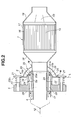
- flare flange unit 20 is caused to pivot relative to annular gasket 14 about an imaginary axis "L" (see Fig. 2) that connects the two bolts 21 while diametrically crossing flare flange unit 20. Due to this pivotal connection, vertical swing movement of exhaust manifold 4 and that of catalytic converter 7, which are inevitably caused by vertical vibration of engine 1, are assuredly and effectively absorbed.
- cylindrical case 17 is produced by curving a single metal plate. That is, as is understood from this drawing, the metal plate is pressed or curved to have a generally S-shaped cross section with a larger round upper part and a smaller rectangular lower part. Then, longitudinal flanged edges of the shaped metal plate are welded to predetermined portions "W". With these steps, there are defined a cylindrical exhaust gas chamber 17a which has catalyst support 15 (not shown in the drawing) received therein and an axially extending passage which constitutes the above-mentioned EGR gas passage 10. As shown, the EGR gas passage 10 extends in parallel with cylindrical exhaust gas chamber 17a and is isolated from the exhaust gas chamber 17a by a part 17b of case 17.
- conical outlet defuser 19 is produced by pressing a circular metal plate. Due to this pressing, a part of the metal plate is radially outwardly expanded to produce a radially expanded grooved portion 23 which serves as the above-mentioned EGR gas inlet port 9.
- EGR gas passage 10 has a downstream open end 10a which is positioned radially outside of conical inlet defuser 18. From the downstream open end 10a, there extends first EGR tube 11 to spheric coupler 6.
- the catalytic converter 7 when properly mounted in the exhaust system, the catalytic converter 7 is inclined in such a manner that its inlet port is positioned higher than its outlet port with respect to a road surface on which the associated motor vehicle stands. Due to this inclination of catalytic converter 7, EGR gas passage 10 inclines also, and thus, stagnation of condensed water in the passage 10 is prevented.
- spheric coupler 6 comprises generally two parts which are, as is seen from Fig. 5, the annular gasket 14 and the flare flange unit 20 which are connected to each other through a so-called spherical bearing connection.
- annular gasket 14 is formed with convex surface 14a and flare flange unit 20 is formed with concave surface 20a. These convex and concave surfaces 14a and 20a are mated to intimately contact to each other. If desired, to the contrary, the convex surface may be provided by flare flange unit 20 and the concave surface may be provided by annular gasket 14.
- annular gasket 14 is formed with two EGR passages 24 at diametrically opposed portions. Also flare flange unit 20 is formed with two EGR openings 25 at diametrically opposed portions.
- these EGR passages 24 and openings 25 are mated with one another at the mutually contacting convex and concave surfaces 14a and 20a.
- the two EGR openings 25 are exposed to a concave enclosed space 26 which is defined between an inner concave member 27a and an outer concave member 27b.
- outer member 27b is welded at its peripheral edge "W" to inner member 27a to constitute the flare flange unit 20.
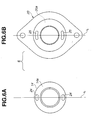
- each of EGR openings 25 of flare flange unit 20 is so sized and shaped as to cover the entire area of the open end of the corresponding EGR passage 24 of annular gasket 14 even when flare flange unit 20 assumes a maximum angular position relative to annular gasket 14.
- each open end of the EGR passages 24 and each EGR opening 25 are shaped elliptical.
- flare flange unit 20 is permitted to pivot about the imaginary axis "L” (see Fig. 2) and thus can assume the maximum angular position that is denoted by reference " ⁇ " in Fig. 7B.
- EGR passages 24 of annular gasket 14 are positioned on the imaginary axis "L” and EGR openings 25 of flare flange unit 20 are also positioned on the imaginary axis "L”. Due to this arrangement, relative displacement between the open ends of EGR passages 24 and their corresponding EGR openings 25 can be minimized, which can reduce the size of the open ends of EGR passages 24 and EGR openings 25.
- concave enclosed space 26 of flare flange unit 20 is communicated with two EGR passages 24 of annular gasket 14 (see Fig. 2) as well as first EGR tube 11 (see Fig. 3) through an inlet opening 28 formed in outer concave member 27b of flare flange unit 20.
- inlet opening 28 is positioned at the lowermost portion of the outer concave member 27b with respect to a road surface on which the associated motor vehicle stands.
- the flange 5 provided on the united downstream portion of exhaust manifold 4 is formed with two EGR passages 29 which are connected with the passages 24 of annular gasket 14 respectively.
- the EGR passages 29 are united and then connected to second EGR tube 12 for connecting with EGR valve 13 (see Fig. 1).
- EGR gas inlet port 9 EGR gas passage 10
- first EGR tube 11 concave enclosed space 26
- two EGR openings 25 two EGR passages 24,
- two EGR passages 29 and second EGR tube 12 constitute a so-called "EGR gas passage line” that conveys a cleaned exhaust gas to the collector unit 3 through EGR valve 13.
- a part of the cleaned exhaust gas, that has passed through catalyst support 15 of catalytic converter 7, is led into EGR gas passage 10 from EGR gas inlet port 9 defined by conical outlet defuser 19.
- the cleaned exhaust gas is then led into first EGR tube 11, concave enclosed space 26 of flare flange unit 20, and then as is seen from Fig. 2, into EGR passages 24 of annular gasket 14 and into EGR passages 29 of the flange 5 and then, as is seen from Fig. 1, into second EGR tube 12 and finally led to the collector unit 3 through EGR valve 13. Due to the EGR gas recirculation as mentioned hereinabove, NOx emissions from the engine 1 can be reduced.
- an intermediate part of the EGR gas passage line that is the part constructed by concave enclosed space 26 of flare flange unit 20, EGR openings 25 of flare flange unit 20, and EGR passages 24 of annular gasket 14, is compactly and effectively provided by spheric coupler 6. That is, as is seen from Fig. 1, the fluid connection between first and second EGR tubes 11 and 12 is kept even when spheric coupler 6 shows its tilted condition (see Fig. 7B) due to an angled position of catalytic converter 7 relative to exhaust manifold 4.
- Spheric coupler 6 is of an articulated type comprising annular gasket 14 with convex surface 14a and flare flange unit 20 with concave surface 20a which intimately and slidably contacts the convex surface 14a.
- Annular gasket 14 is formed with EGR passages 24 and flare flange unit 20 is formed with EGR openings 25 mated with concave enclosed space 26.
- EGR passages 24 and EGR openings 25 are mated at the area where convex surface 14a and concave surface 20a intimately contact.
- each of EGR openings 25 of flare flange unit 20 is so sized and shaped as to cover the entire area of the open end of the corresponding EGR passage 24 of annular gasket 14 even when flare flange unit 20 is largely angled relative to annular gasket 14.
- EGR gas flow in the EGR gas passage line is smoothly and assuredly carried out even when a large relative angle is kept between flare flange unit 20 and annular gasket 14.
- flare flange unit 20 Due to provision of two bolts 21 (see Fig. 2) that loosely connect flare flange unit 20 to the flange 5 of the exhaust manifold 4, flare flange unit 20 is caused to pivot relative to annular gasket 14 about the imaginary axis "L". Accordingly, relative displacement between the open ends of EGR passages 24 of annular gasket 14 and their corresponding EGR openings 25 of flare flange unit 20 can be minimized, which can reduce the size of the open ends of EGR passages and EGR openings 25.
- two EGR passages 24 of annular gasket 14 and two EGR openings 25 of flare'flange unit 20 are provided at diametrically opposed positions of spheric coupler 6, not only a mechanically balanced construction of spheric coupler 6 but also a hydro-mechanically balanced flow of EGR gas is achieved in the EGR gas passage line.
- the welded portions "W" of flare flange unit 20 are kept away from the mutually contacting convex and concave surfaces 14a and 20a of spheric coupler 6.
- the heat generated during the welding has substantially no influence on such surfaces 14a and 20a, and thus, a sealing ability possessed by the surfaces 14a and 20a is kept unchanged.
- the welded portions "W" are exposed to the open area, the welding at such portions "W” is easily carried out.
- the opening 28 of outer concave member 27b of flare flange unit 20 is positioned at the lowermost portion of the member 27b. Accordingly, condensed water inevitably produced in concave enclosed space 26 of flare flange unit 20 is smoothly drained therefrom, and thus, flare flange unit 20 is suppressed from having rust.
- an upstream part of the EGR gas passage line that is, the part constructed by EGR gas inlet port 9 and EGR gas passage 10, is neatly, compactly and integrally provided by case 17 of catalytic converter 7.
- the exhaust gas recirculation device 100 can be simplified in construction and reduced in size. As is known, the exhaust gas recirculation device 100 having such features is easily mounted in an engine room even when the engine room has a limited space.
- EGR gas inlet port 9 is provided by pressing a part of conical outlet defuser 19 (see Fig. 4B) and EGR gas passage 10 is provided by curving or pressing a single metal plate to have a generally S-shaped cross section (see Fig. 4A).
- the upstream part of the EGR gas passage line can be provided at a lower cost.
- EGR gas inlet port 9 is positioned and constructed to receive a cleaned exhaust gas that has passed through catalytic converter 7, the interior of the EGR gas passage line is entirely protected from collecting unwanted deposits.
- catalytic converter 7 upon mounting on a motor vehicle, catalytic converter 7 is postured to incline with its inlet port positioned higher than its outlet port with respect to the road surface. Due to this inclination of catalytic converter 7, EGR gas passage 10 inclines also, and thus, stagnation of condensed water in the passage 10 is prevented. Thus, the passage 10 is protected from having rust.
- FIG. 8 there is shown an exhaust gas recirculation device 200, which is a second embodiment of the present invention.
- an EGR gas inlet port 31 is provided in exhaust pipe 8 downstream of catalytic converter 7, and an EGR tube 32 extends from EGR gas inlet port 31 to inlet opening 28 formed in outer concave member 27b of flare flange unit 20.
- the fluid connection between the two EGR tubes 32 and 12 is assuredly kept even when spheric coupler 6 shows its tilted condition (see Fig. 7B) due to an angled position of catalytic converter 7 relative to exhaust manifold 4.
Landscapes
- Engineering & Computer Science (AREA)
- Chemical & Material Sciences (AREA)
- Combustion & Propulsion (AREA)
- Mechanical Engineering (AREA)
- General Engineering & Computer Science (AREA)
- Exhaust-Gas Circulating Devices (AREA)
- Exhaust Gas After Treatment (AREA)
- Exhaust Silencers (AREA)
Abstract
Description
Claims (16)
- An exhaust gas recirculation device (100, 200) for use with an internal combustion engine (1) which has a spheric coupler through which an exhaust manifold (4) and a catalytic converter (7) are pivotally connected, comprising:wherein at least a part of the EGR gas passage line is constructed by a passage (24, 25, 26) defined in the spheric coupler (6).an EGR gas inlet port (9, 31) provided in a downstream portion of the catalytic converter (7); andan EGR gas passage line (10, 11, 24, 25, 26, 12, 32) extending from the EGR gas inlet port (9) to an intake system (3) of the engine (1),
- An exhaust gas recirculation device as claimed in Claim 1, in which the spheric coupler comprises:a first member (14) having a convex surface (14a) and connected to one (4) of the exhaust manifold (4) and the catalytic converter (7);a second member (20) having a concave surface (20a) intimately contactable with the convex surface (14a) of the first member (14), the second member (20) being connected to the other (7) of the exhaust manifold (4) and the catalytic converter (7);a first EGR passage (24) defined in the first member (14); anda second EGR passage (25, 26) defined in the second member (20) and constantly exposed to the first EGR passage (24) of the first member (14).
- An exhaust gas recirculation device as claimed in Claim 2, in which one of mutually facing open ends of the first and second EGR passages (24, 25, 26) is so sized and shaped as to cover the entire area of the other of the mutually facing open ends even when the first and second members (14, 20) show a maximum relative angle therebetween.
- An exhaust gas recirculation device as claimed in Claim 3, in which the spheric coupler further comprises a pivot direction controller (21, 22) by which the second member (20) is permitted to pivot about a given axis relative to the first member (14), and in which the mutually facing ends of the first and second EGR passages (24, 25, 26) are positioned on the given axis.
- An exhaust gas recirculation device as claimed in Claim 4, in which the pivot direction controller (21, 22) comprises:two bolt holes formed in diametrically opposed portions of the second member (20);two bolts (21) respectively passing through the two bolt holes to loosely connect the second member (20) to a member (5) fixed to the first member (14); andtwo coil springs (22) respectively disposed about the two bolts (21) to bias the concave surface (20a) of the second member (20) against the convex surface (14a) of the first member (14).
- An exhaust gas recirculation device as claimed in Claim 2, in which each of the first and second EGR passages (24, 25, 26) comprises two passages that are provided at diametrically opposed positions of the spheric coupler.
- An exhaust gas recirculation device as claimed in Claim 2, in which the second member (20) is a flare flange unit which comprises:an inner concave member (27a) having the concave surface (20a) contactable with the convex surface (14a) of the first member (14);an outer concave member (27b) welded at its peripheral edge to the inner concave member (27a) in a manner to define therebetween a concave enclosed space (26), the concave enclosed space (26) constituting the second EGR passage (25, 26) of the second member (20).
- An exhaust gas recirculation device as claimed in Claim 7, in which the outer concave member (27b) is formed with an inlet opening (28) to which a tube (11, 32) connected to the EGR gas inlet port (9, 31) is connected.
- An exhaust gas recirculation device as claimed in Claim 8, in which, upon assembly of the exhaust gas recirculation device (100, 200) in an engine room of a motor vehicle, the inlet opening (28) is positioned at the lowermost portion of the outer concave member (27b) with respect to a road surface on which the motor vehicle stands.
- An exhaust gas recirculation device as claimed in Claim 1, further comprising an EGR gas passage (10) which is integrally formed on and along a side wall of the catalytic converter (7), the EGR gas passage (10) constituting at least a part of the EGR gas passage line.
- An exhaust gas recirculation device as claimed in Claim 10, in which the EGR gas passage (10) extends along an axis of a case (17) of the catalytic converter (7), the case (17) having a catalytic support (15) installed therein, and in which the EGR gas passage (10) has an inlet part exposed to the EGR gas inlet port (9).
- An exhaust gas recirculation device as claimed in Claim 11, in which the EGR gas passage (10) is integrally provided by the case (17) of the catalytic converter (7).
- An exhaust gas recirculation device as claimed in Claim 12, in which the case (17) of the catalytic converter (7) is provided by pressing a metal plate to have a generally S-shaped cross section with a larger round upper part and a smaller rectangular smaller part, and welding given edges of the shaped metal plate, the shaped and welded metal plate constituting the EGR gas passage (10) at a portion that has the smaller rectangular lower part.
- An exhaust gas recirculation device as claimed in Claim 13, in which the EGR gas inlet port (9) is defined by a radially expanded grooved portion (23) of an outlet defuser (19) of the catalytic converter (7), the groove of the radially expanded grooved portion (23) being exposed to the inlet part of the EGR gas passage (10).
- An exhaust gas recirculation device as claimed in Claim 1, in which, upon assembly of the exhaust gas recirculation device (100, 200) in an engine room of a motor vehicle, the catalyst converter (7) is inclined in such a manner that its inlet port is positioned higher than its outlet port with respect to a road surface on which the motor vehicle stands.
- An exhaust gas recirculation device (200) for use with an internal combustion engine (1) having an exhaust manifold (4) to which a catalytic converter (7) is pivotally connected through a spheric coupler (6), comprising:an EGR gas inlet port (9) provided in an exhaust pipe (8) downstream of the catalytic converter (7);a passage (24, 25, 26) defined in the spheric coupler (6), the passage of the spheric coupler keeping its open condition even when the spheric coupler (6) assumes a tilted position;a first EGR tube (32) extending from the EGR gas inlet port (9) to an inlet part of the passage (24, 25, 26) of the spheric coupler (6); anda second EGR tube (12) extending from an outlet part of the passage (24, 25, 26) of the spheric coupler (6) to an intake system (3) of the engine (1).
Applications Claiming Priority (2)
| Application Number | Priority Date | Filing Date | Title |
|---|---|---|---|
| JP2002340646A JP4048931B2 (en) | 2002-11-25 | 2002-11-25 | EGR device for engine |
| JP2002340646 | 2002-11-25 |
Publications (3)
| Publication Number | Publication Date |
|---|---|
| EP1422411A2 true EP1422411A2 (en) | 2004-05-26 |
| EP1422411A3 EP1422411A3 (en) | 2006-08-09 |
| EP1422411B1 EP1422411B1 (en) | 2010-12-22 |
Family
ID=32212153
Family Applications (1)
| Application Number | Title | Priority Date | Filing Date |
|---|---|---|---|
| EP03026729A Expired - Lifetime EP1422411B1 (en) | 2002-11-25 | 2003-11-21 | Exhaust gas recirculation device of internal combustion engine |
Country Status (5)
| Country | Link |
|---|---|
| EP (1) | EP1422411B1 (en) |
| JP (1) | JP4048931B2 (en) |
| KR (1) | KR100589101B1 (en) |
| CN (2) | CN1308575C (en) |
| DE (1) | DE60335442D1 (en) |
Cited By (4)
| Publication number | Priority date | Publication date | Assignee | Title |
|---|---|---|---|---|
| DE102016121434A1 (en) * | 2016-11-09 | 2018-05-09 | Man Diesel & Turbo Se | Exhaust after-treatment system of an internal combustion engine |
| US10443476B2 (en) | 2017-10-12 | 2019-10-15 | Toyota Jidosha Kabushiki Kaisha | Catalyst device |
| CN111033014A (en) * | 2017-08-24 | 2020-04-17 | 马自达汽车株式会社 | Engine for vehicle |
| US20230417166A1 (en) * | 2022-06-23 | 2023-12-28 | Greener Process Systems Inc. | Exhaust Capture Devices And Methods |
Families Citing this family (3)
| Publication number | Priority date | Publication date | Assignee | Title |
|---|---|---|---|---|
| JP4048931B2 (en) * | 2002-11-25 | 2008-02-20 | 日産自動車株式会社 | EGR device for engine |
| JP5791458B2 (en) * | 2011-10-12 | 2015-10-07 | 本田技研工業株式会社 | Exhaust gas recirculation device for internal combustion engine |
| JP2020197169A (en) * | 2019-06-03 | 2020-12-10 | 株式会社豊田自動織機 | Ammonia combustion system |
Family Cites Families (8)
| Publication number | Priority date | Publication date | Assignee | Title |
|---|---|---|---|---|
| US5374086A (en) * | 1992-07-29 | 1994-12-20 | Creative Industries Group, Inc. | Ball joint seal for vehicle exhaust system |
| JP3248806B2 (en) * | 1994-03-18 | 2002-01-21 | 本田技研工業株式会社 | Exhaust gas purification device for internal combustion engine |
| JPH08291772A (en) * | 1995-04-20 | 1996-11-05 | Mazda Motor Corp | EGR gas extraction structure of engine |
| JP3250458B2 (en) * | 1996-05-31 | 2002-01-28 | トヨタ自動車株式会社 | Exhaust pipe connection structure of internal combustion engine |
| JP3658115B2 (en) * | 1996-11-20 | 2005-06-08 | 本田技研工業株式会社 | Exhaust gas purification device for internal combustion engine |
| JP4434401B2 (en) * | 2000-01-19 | 2010-03-17 | 本田技研工業株式会社 | Exhaust gas purification device for internal combustion engine |
| JP2002285916A (en) * | 2001-03-27 | 2002-10-03 | Mitsubishi Motors Corp | Exhaust recirculation device |
| JP4048931B2 (en) * | 2002-11-25 | 2008-02-20 | 日産自動車株式会社 | EGR device for engine |
-
2002
- 2002-11-25 JP JP2002340646A patent/JP4048931B2/en not_active Expired - Lifetime
-
2003
- 2003-11-21 DE DE60335442T patent/DE60335442D1/en not_active Expired - Lifetime
- 2003-11-21 EP EP03026729A patent/EP1422411B1/en not_active Expired - Lifetime
- 2003-11-24 KR KR1020030083424A patent/KR100589101B1/en not_active Expired - Lifetime
- 2003-11-25 CN CNB2003101183529A patent/CN1308575C/en not_active Expired - Lifetime
- 2003-11-25 CN CNU2003201167875U patent/CN2742167Y/en not_active Expired - Lifetime
Cited By (8)
| Publication number | Priority date | Publication date | Assignee | Title |
|---|---|---|---|---|
| DE102016121434A1 (en) * | 2016-11-09 | 2018-05-09 | Man Diesel & Turbo Se | Exhaust after-treatment system of an internal combustion engine |
| DE102016121434B4 (en) | 2016-11-09 | 2022-10-27 | Man Energy Solutions Se | Exhaust aftertreatment system of an internal combustion engine |
| CN111033014A (en) * | 2017-08-24 | 2020-04-17 | 马自达汽车株式会社 | Engine for vehicle |
| EP3660291A4 (en) * | 2017-08-24 | 2020-08-19 | Mazda Motor Corporation | VEHICLE ENGINE |
| US11008984B2 (en) | 2017-08-24 | 2021-05-18 | Mazda Motor Corporation | Motor vehicle on which a vehicle engine is mounted |
| US10443476B2 (en) | 2017-10-12 | 2019-10-15 | Toyota Jidosha Kabushiki Kaisha | Catalyst device |
| US20230417166A1 (en) * | 2022-06-23 | 2023-12-28 | Greener Process Systems Inc. | Exhaust Capture Devices And Methods |
| US12286912B2 (en) * | 2022-06-23 | 2025-04-29 | Greener Process Systems Inc. | Exhaust capture devices and methods |
Also Published As
| Publication number | Publication date |
|---|---|
| CN1308575C (en) | 2007-04-04 |
| EP1422411B1 (en) | 2010-12-22 |
| KR20040045365A (en) | 2004-06-01 |
| EP1422411A3 (en) | 2006-08-09 |
| JP2004176553A (en) | 2004-06-24 |
| CN2742167Y (en) | 2005-11-23 |
| KR100589101B1 (en) | 2006-06-14 |
| DE60335442D1 (en) | 2011-02-03 |
| CN1502802A (en) | 2004-06-09 |
| JP4048931B2 (en) | 2008-02-20 |
Similar Documents
| Publication | Publication Date | Title |
|---|---|---|
| EP1422412A2 (en) | Exhaust gas recirculation device of internal combustion engine | |
| US8459016B2 (en) | Exhaust manifold for internal combustion engine | |
| EP1331388B1 (en) | Exhaust gas recirculation device for engines | |
| US20080178585A1 (en) | Exhaust treatment device having flow-promoting end caps | |
| US11333255B2 (en) | Valve assembly | |
| EP1422411B1 (en) | Exhaust gas recirculation device of internal combustion engine | |
| JP4094423B2 (en) | Exhaust device for internal combustion engine | |
| JP6591791B2 (en) | Internal combustion engine for vehicles | |
| CN113167165A (en) | Exhaust heat recovery system | |
| US11391195B2 (en) | Exhaust system and muffler | |
| FR2926845A1 (en) | Flexible exhaust pipe element for motor vehicle, has flexible inner and outer tubes maintained in relative position by end flanges, where inner tube defines central passage, and annular channel formed between inner and outer tubes | |
| CN107605585A (en) | Waste gas seal | |
| US6474697B2 (en) | Exhaust elbow | |
| EP0647779A1 (en) | Exhaust gas recirculation device for an internal combustion engine | |
| CN103306795A (en) | Dual pipe exhaust manifold | |
| US10557443B2 (en) | Exhaust device of engine | |
| US20220220874A1 (en) | Exhaust system and muffler | |
| US20090077956A1 (en) | Flexible Exhaust Pipe Coupling |
Legal Events
| Date | Code | Title | Description |
|---|---|---|---|
| PUAI | Public reference made under article 153(3) epc to a published international application that has entered the european phase |
Free format text: ORIGINAL CODE: 0009012 |
|
| 17P | Request for examination filed |
Effective date: 20031121 |
|
| AK | Designated contracting states |
Kind code of ref document: A2 Designated state(s): AT BE BG CH CY CZ DE DK EE ES FI FR GB GR HU IE IT LI LU MC NL PT RO SE SI SK TR |
|
| AX | Request for extension of the european patent |
Extension state: AL LT LV MK |
|
| PUAL | Search report despatched |
Free format text: ORIGINAL CODE: 0009013 |
|
| AK | Designated contracting states |
Kind code of ref document: A3 Designated state(s): AT BE BG CH CY CZ DE DK EE ES FI FR GB GR HU IE IT LI LU MC NL PT RO SE SI SK TR |
|
| AX | Request for extension of the european patent |
Extension state: AL LT LV MK |
|
| AKX | Designation fees paid |
Designated state(s): DE FR GB |
|
| GRAP | Despatch of communication of intention to grant a patent |
Free format text: ORIGINAL CODE: EPIDOSNIGR1 |
|
| GRAS | Grant fee paid |
Free format text: ORIGINAL CODE: EPIDOSNIGR3 |
|
| GRAA | (expected) grant |
Free format text: ORIGINAL CODE: 0009210 |
|
| AK | Designated contracting states |
Kind code of ref document: B1 Designated state(s): DE FR GB |
|
| REG | Reference to a national code |
Ref country code: GB Ref legal event code: FG4D |
|
| REF | Corresponds to: |
Ref document number: 60335442 Country of ref document: DE Date of ref document: 20110203 Kind code of ref document: P |
|
| REG | Reference to a national code |
Ref country code: DE Ref legal event code: R096 Ref document number: 60335442 Country of ref document: DE Effective date: 20110203 |
|
| PLBE | No opposition filed within time limit |
Free format text: ORIGINAL CODE: 0009261 |
|
| STAA | Information on the status of an ep patent application or granted ep patent |
Free format text: STATUS: NO OPPOSITION FILED WITHIN TIME LIMIT |
|
| 26N | No opposition filed |
Effective date: 20110923 |
|
| REG | Reference to a national code |
Ref country code: DE Ref legal event code: R097 Ref document number: 60335442 Country of ref document: DE Effective date: 20110923 |
|
| REG | Reference to a national code |
Ref country code: FR Ref legal event code: PLFP Year of fee payment: 13 |
|
| REG | Reference to a national code |
Ref country code: FR Ref legal event code: PLFP Year of fee payment: 14 |
|
| REG | Reference to a national code |
Ref country code: FR Ref legal event code: PLFP Year of fee payment: 15 |
|
| REG | Reference to a national code |
Ref country code: FR Ref legal event code: PLFP Year of fee payment: 16 |
|
| PGFP | Annual fee paid to national office [announced via postgrant information from national office to epo] |
Ref country code: GB Payment date: 20220930 Year of fee payment: 20 |
|
| PGFP | Annual fee paid to national office [announced via postgrant information from national office to epo] |
Ref country code: FR Payment date: 20221010 Year of fee payment: 20 |
|
| PGFP | Annual fee paid to national office [announced via postgrant information from national office to epo] |
Ref country code: DE Payment date: 20220930 Year of fee payment: 20 |
|
| REG | Reference to a national code |
Ref country code: DE Ref legal event code: R071 Ref document number: 60335442 Country of ref document: DE |
|
| REG | Reference to a national code |
Ref country code: GB Ref legal event code: PE20 Expiry date: 20231120 |
|
| PG25 | Lapsed in a contracting state [announced via postgrant information from national office to epo] |
Ref country code: GB Free format text: LAPSE BECAUSE OF EXPIRATION OF PROTECTION Effective date: 20231120 |
|
| PG25 | Lapsed in a contracting state [announced via postgrant information from national office to epo] |
Ref country code: GB Free format text: LAPSE BECAUSE OF EXPIRATION OF PROTECTION Effective date: 20231120 |