EP1421894B2 - Endoscope head - Google Patents
Endoscope head Download PDFInfo
- Publication number
- EP1421894B2 EP1421894B2 EP03026488A EP03026488A EP1421894B2 EP 1421894 B2 EP1421894 B2 EP 1421894B2 EP 03026488 A EP03026488 A EP 03026488A EP 03026488 A EP03026488 A EP 03026488A EP 1421894 B2 EP1421894 B2 EP 1421894B2
- Authority
- EP
- European Patent Office
- Prior art keywords
- endoscope head
- endoscope
- head according
- assembly
- functional
- Prior art date
- Legal status (The legal status is an assumption and is not a legal conclusion. Google has not performed a legal analysis and makes no representation as to the accuracy of the status listed.)
- Expired - Lifetime
Links
- 230000001681 protective effect Effects 0.000 claims description 20
- 230000003287 optical effect Effects 0.000 claims description 10
- 239000000969 carrier Substances 0.000 claims description 9
- 239000000463 material Substances 0.000 claims description 7
- 238000005286 illumination Methods 0.000 claims 2
- 239000012780 transparent material Substances 0.000 claims 1
- 238000011010 flushing procedure Methods 0.000 description 15
- 238000004659 sterilization and disinfection Methods 0.000 description 5
- 230000007704 transition Effects 0.000 description 4
- 238000003780 insertion Methods 0.000 description 2
- 230000037431 insertion Effects 0.000 description 2
- 239000007788 liquid Substances 0.000 description 2
- 238000004519 manufacturing process Methods 0.000 description 2
- 238000000034 method Methods 0.000 description 2
- 238000010926 purge Methods 0.000 description 2
- 230000001954 sterilising effect Effects 0.000 description 2
- 230000001154 acute effect Effects 0.000 description 1
- 238000005452 bending Methods 0.000 description 1
- 230000005540 biological transmission Effects 0.000 description 1
- 238000004140 cleaning Methods 0.000 description 1
- 238000004891 communication Methods 0.000 description 1
- 238000010276 construction Methods 0.000 description 1
- 238000007796 conventional method Methods 0.000 description 1
- 238000013461 design Methods 0.000 description 1
- 201000010099 disease Diseases 0.000 description 1
- 208000037265 diseases, disorders, signs and symptoms Diseases 0.000 description 1
- 239000003814 drug Substances 0.000 description 1
- 244000005700 microbiome Species 0.000 description 1
- 238000012986 modification Methods 0.000 description 1
- 230000004048 modification Effects 0.000 description 1
- 210000000056 organ Anatomy 0.000 description 1
- 238000005192 partition Methods 0.000 description 1
- 244000052769 pathogen Species 0.000 description 1
- 229920001296 polysiloxane Polymers 0.000 description 1
- 239000007787 solid Substances 0.000 description 1
- 238000005406 washing Methods 0.000 description 1
Images


Classifications
-
- A—HUMAN NECESSITIES
- A61—MEDICAL OR VETERINARY SCIENCE; HYGIENE
- A61B—DIAGNOSIS; SURGERY; IDENTIFICATION
- A61B1/00—Instruments for performing medical examinations of the interior of cavities or tubes of the body by visual or photographical inspection, e.g. endoscopes; Illuminating arrangements therefor
- A61B1/04—Instruments for performing medical examinations of the interior of cavities or tubes of the body by visual or photographical inspection, e.g. endoscopes; Illuminating arrangements therefor combined with photographic or television appliances
- A61B1/05—Instruments for performing medical examinations of the interior of cavities or tubes of the body by visual or photographical inspection, e.g. endoscopes; Illuminating arrangements therefor combined with photographic or television appliances characterised by the image sensor, e.g. camera, being in the distal end portion
- A61B1/051—Details of CCD assembly
-
- A—HUMAN NECESSITIES
- A61—MEDICAL OR VETERINARY SCIENCE; HYGIENE
- A61B—DIAGNOSIS; SURGERY; IDENTIFICATION
- A61B1/00—Instruments for performing medical examinations of the interior of cavities or tubes of the body by visual or photographical inspection, e.g. endoscopes; Illuminating arrangements therefor
- A61B1/00064—Constructional details of the endoscope body
- A61B1/00071—Insertion part of the endoscope body
- A61B1/0008—Insertion part of the endoscope body characterised by distal tip features
- A61B1/00096—Optical elements
-
- A—HUMAN NECESSITIES
- A61—MEDICAL OR VETERINARY SCIENCE; HYGIENE
- A61B—DIAGNOSIS; SURGERY; IDENTIFICATION
- A61B1/00—Instruments for performing medical examinations of the interior of cavities or tubes of the body by visual or photographical inspection, e.g. endoscopes; Illuminating arrangements therefor
- A61B1/00064—Constructional details of the endoscope body
- A61B1/00103—Constructional details of the endoscope body designed for single use
-
- A—HUMAN NECESSITIES
- A61—MEDICAL OR VETERINARY SCIENCE; HYGIENE
- A61B—DIAGNOSIS; SURGERY; IDENTIFICATION
- A61B1/00—Instruments for performing medical examinations of the interior of cavities or tubes of the body by visual or photographical inspection, e.g. endoscopes; Illuminating arrangements therefor
- A61B1/00064—Constructional details of the endoscope body
- A61B1/00105—Constructional details of the endoscope body characterised by modular construction
-
- A—HUMAN NECESSITIES
- A61—MEDICAL OR VETERINARY SCIENCE; HYGIENE
- A61B—DIAGNOSIS; SURGERY; IDENTIFICATION
- A61B1/00—Instruments for performing medical examinations of the interior of cavities or tubes of the body by visual or photographical inspection, e.g. endoscopes; Illuminating arrangements therefor
- A61B1/04—Instruments for performing medical examinations of the interior of cavities or tubes of the body by visual or photographical inspection, e.g. endoscopes; Illuminating arrangements therefor combined with photographic or television appliances
- A61B1/05—Instruments for performing medical examinations of the interior of cavities or tubes of the body by visual or photographical inspection, e.g. endoscopes; Illuminating arrangements therefor combined with photographic or television appliances characterised by the image sensor, e.g. camera, being in the distal end portion
- A61B1/053—Instruments for performing medical examinations of the interior of cavities or tubes of the body by visual or photographical inspection, e.g. endoscopes; Illuminating arrangements therefor combined with photographic or television appliances characterised by the image sensor, e.g. camera, being in the distal end portion being detachable
-
- A—HUMAN NECESSITIES
- A61—MEDICAL OR VETERINARY SCIENCE; HYGIENE
- A61B—DIAGNOSIS; SURGERY; IDENTIFICATION
- A61B1/00—Instruments for performing medical examinations of the interior of cavities or tubes of the body by visual or photographical inspection, e.g. endoscopes; Illuminating arrangements therefor
- A61B1/00112—Connection or coupling means
- A61B1/00121—Connectors, fasteners and adapters, e.g. on the endoscope handle
-
- A—HUMAN NECESSITIES
- A61—MEDICAL OR VETERINARY SCIENCE; HYGIENE
- A61B—DIAGNOSIS; SURGERY; IDENTIFICATION
- A61B1/00—Instruments for performing medical examinations of the interior of cavities or tubes of the body by visual or photographical inspection, e.g. endoscopes; Illuminating arrangements therefor
- A61B1/12—Instruments for performing medical examinations of the interior of cavities or tubes of the body by visual or photographical inspection, e.g. endoscopes; Illuminating arrangements therefor with cooling or rinsing arrangements
- A61B1/121—Instruments for performing medical examinations of the interior of cavities or tubes of the body by visual or photographical inspection, e.g. endoscopes; Illuminating arrangements therefor with cooling or rinsing arrangements provided with means for cleaning post-use
Definitions
- the invention relates to an endoscope head with a plurality of functional units or elements according to the preamble of patent claim 1.
- Endoscopes are used especially in medicine for the diagnostic observation (reflection) of body cavities and hollow organs.
- flexible endoscopes are well known, which have an operation for the insertion of implements and an endoscope head, which may be equipped with lighting devices, image transmission devices and other facilities.
- endoscopes are provided with endoscope heads, consisting of a number of electrical, optical and hydraulic functional elements, which are placed on a holder and then encapsulated with a body-compatible material such as silicone. This process is carried out in such a way that the distal end of the endoscope shaft, on which the head is mounted, is also encapsulated at the same time in order to seal the transition between the endoscope head and the endoscope shaft.
- a disposable endoscope particularly a head for a disposable endoscope, which can be manufactured so easily and inexpensively that it can be disposed of after use.
- the core of the invention is therefore that the endoscope head is constructed from a number of modular functional carriers for receiving and / or forming correspondingly assigned functional units, which the endoscope must have according to its intended use.
- the function carriers are equipped with the corresponding Funtionsajien or elements before assembly and then preferably assembled by snap or clamp connections.
- a kind of adapter or mounting adapter provided which establishes or allows a connection between the functional elements of the head and the corresponding lines and channels in the endoscope shaft.
- the cap is at least partially constructed of a translucent material, wherein the electronic components also have an opt.
- Sensor chip include luminous body.
- the modular parts can be produced very inexpensively and the head can be mounted. By reducing the manufacturing costs of the head can thus be created an endoscope that can be used as a disposable endoscope.
- FIGS. 1 to 4 An endoscope with endoscope head according to an embodiment of the invention will be described.
- the endoscope basically consists of a flexible endoscope shaft or tube (not shown) which accommodates a centrally extending working channel 1, a mounting adapter 2 fixed to the one distal end of the endoscope tube and an endoscope head 3 attached to the endoscope tube via the mounting adapter 2 is.
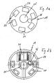
- the endoscope head 3 according to the invention in turn consists essentially of a number of modular functional supports 19, 22, 23 for receiving and / or forming correspondingly assigned specific functional units 20, 21, 38, which the endoscope head requires to perform, for example, an examination on a human body cavity.
- the endoscope tube is of interest for the invention described herein insofar as the mounting adapter 2 is formed quasi as an intermediate piece for receiving or linking certain elements of the endoscope tube with the endoscope head.
- the endoscope tube has (not shown) Abkrümmungsiata for bending of its distal end, via (also not shown) current or photoconductive cables or lines that supply the electronic components 20, 21 in the endoscope head 3 with power, or transmitted by the information can be and via a double channel 4 consisting of an internal working channel 1 for insertion of working instruments in the cavity to be considered and an external flushing channel 5 for supplying a mounted on the endoscope 3 flushing nozzle 6 with rinsing liquid, which represents a further functional unit.
- this channel arrangement is to be understood as consisting of two cylindrical channel elements or tubes 1a, 7 with different outside diameters, the smaller channel element 1a being located in the larger channel element 7 so that its channel walls are tangent to a longitudinal side, i. they are coaxial, but arranged offset to each other.
- the inner channel element 1a of the working channel 1 and from the area between the outer 7 and inner channel element 1a is formed, in this case crescent-shaped flushing channel 5.
- the two channel elements 1a, 7 have different longitudinal axes by the difference their radii (hereinafter referred to as the axial offset) are offset.
- the inner channel element 1a is longer than the outer channel element 7 by an amount determined by the height of the endoscope head.
- the double channel 4 is only continued from the working channel 1 from a certain position.
- the mounting adapter 2 according to the Fig. 3 and 4 consists essentially of two concentric nested cylinder elements 8, 9 with different radii, which are connected to each other via an axis perpendicular to the cylinder axis adapter plate 10, which is preferably formed integrally therewith on one end face of the two cylinder elements 8, 9.
- the outer cylinder element 9 has an outer diameter which substantially corresponds to the outer diameter of the endoscope tube and the inner diameter of the inner cylinder member 8 substantially corresponds to the outer diameter of the double channel 4.
- a circular hole 11 in the adapter plate 10 has an inner diameter corresponding to the outer diameter of the working channel 1 and its center is offset with respect to the center of the cylinder elements 8, 9 by the offset of the channel elements.
- a sickle-shaped projection which serves as a support of the mounting adapter 2 on the double channel 4.
- the circular segment-like cavity between the cylinder elements 8, 9 is divided into three sections by radial ribs 12 and in the middle of each section is a cylindrical receiving means 13 for receiving the Abkrümmungsiata, which extends axially and the wall with both the inner 8 and the outer 9 concentric cylindrical element of the adapter 2 is in contact.
- a cylindrical receiving means 13 for receiving the Abkrümmungsiata, which extends axially and the wall with both the inner 8 and the outer 9 concentric cylindrical element of the adapter 2 is in contact.
- On both sides of the receiving means 13 are each two cylindrical cable guides 14 are arranged, which also extend axially and the wall is in contact both with the inner cylinder member 8 and with the receiving means 13.
- two opposing notches 17 are provided on the outer edge of the mounting plate 10, which notch both the adapter plate 10 at its edge and the outer cylinder member 9 and which are radially opposite each other.
- an annular recess 45 is provided on the outer edge of the outer cylinder 9.
- the mounting adapter 2 has on its mounting plate 10 via a rinsing liquid tube 18 which extends parallel to and in the region of the working channel 1 without flushing channel when the mounting adapter 2 is placed on the endoscope tube and the via an opening in the adapter plate 10 with the Flushing channel 5 is connected.
- the mounting adapter 2 can now be easily pushed onto the working channel 1, wherein at the transition between the Adapter plate 10 and the inner cylinder member 8 crescent-shaped projection on a transition between Working channel with flushing channel (double channel) 4 and without flushing channel 1 rests, the cable can be connected through the cable guides 14 with the contact points 16 and the Abkrümmungs institute the endoscope tube with the receiving means 13.
- the support member 19 has a plate shape substantially corresponding to the shape of the mounting plate 10, the axis of the outer edge and the axis of the inner circular hole 25 of the support plate 19 are thus again offset by the offset of the two channel elements 1, 7 to each other.
- it has at its outer edge two notches 24 and an eccentric Spellerloch 26 is worked through the support member 19, through which the flushing pipe 18 can be passed therethrough.
- the contact pads 27 are arranged at a uniform distance from each other, which are in contact with the contact points 16 of the mounting plate 10 when the support member 19 rests on the mounting plate 10 and the notch 17, 24 are each flush.
- the contact fields 27 establish an electrical contact between the underside and the upper side of the carrier plate 19.
- On the upper side of the carrier plate are four luminous bodies 20, which are in each case in communication with one of the contact fields 27 and an optical sensor chip 21 is in contact with a further contact field 27 of the carrier element, which is located in the vicinity of one of the two notches 24. If one draws a line between the centers of the opposing notches 24, then the line halves both the support plate 19 and the optical sensor chip 21 and two luminous bodies 20 are arranged symmetrically to this line.
- the support element for the optics 22 consists essentially of a cubic sensor chip chamber 28, an overlying, divided by a partition wall of the sensor ortimechipformat 28, cylindrical lens chamber 29, one extending next to the two chambers in the axial direction cylindrical working channel passage 30 and a
- a chamfered stiffening rib 32 is arranged laterally of the working passage duct 30.
- the superimposed chambers 28, 29, the working channel passage 30 and the rib 32 are each symmetrical with respect to a common to the support member 19 perpendicular and the support member 19 halving plane.
- the Spülrohr barn® 31 is disposed outside this plane. As further from the Fig. 3 it can be seen, they formed the support member 22 in one piece.
- the support member 22 Up to a certain height, the support member 22 has a shape of the associated chambers 28, 29 and bushings 30, 31 corresponding, enveloping these shapes outer contour. From the certain height, the outer contour changes into the shape of a round disc 33, which has a return 34 at its upper end.
- a round disc 33 which has a return 34 at its upper end.
- the height of the recess 34 substantially corresponds to the thickness of a protective cap 23 described later.
- the sensor chip chamber 28 is open at the bottom and has dimensions such that it can accommodate or surround the sensor chip 21. Overlying the cylindrical lens chamber 29 is arranged and both chambers are separated by a wall 37 having a central hole.
- the lens chamber 29 accommodates at least one optical lens 38 or a lens system which can optionally be designed to be zoomable and are either fixed directly to lens holders or can be introduced into the chamber into the chamber in the form of a prefabricated cartridge.
- the lens chamber 29 is open at the top, but it is preferably covered with a translucent cover 39.
- the working channel passage 30 has up to a certain height an inner diameter corresponding to the outer diameter of the working channel 1 without flushing channel. At its end there is a recess 40 whose return depth corresponds to the thickness of the working channel 1 in the area without flushing channel.
- the purge pipe passage 31 has an inner diameter substantially equal to the outer diameter of the purge pipe 18, and terminates at the upper end of the lens holding member 22 in the nozzle 6 directed to the cover of the lens chamber 29.
- the distance between the midpoint between the Staples 41 and the axis of the working channel passage 30 again corresponds to the offset of the two channel elements 1, 7.
- the protective cap 23 has substantially the shape of an inverted cup or cup. Its inner diameter corresponds to the outer diameter of the carrier element 19 and its "cup bottom" 44 has a circular opening 42 whose diameter corresponds to the diameter of the upper, conical disc 36 of the lens holding member 22 at half height. The inner edge of the opening 42 in the "cup bottom” is rounded and the cap 23 is at least partially made of a translucent material and is overall stronger than the material of the support member 22 for the optics. Furthermore, the protective cap 23 has an annular projection 46 on its inner wall.
- the carrier element 19 is, as described above, equipped with the luminous bodies 20 and the optical sensor chip 21. Then, the support member 22 holding the optical lens 38 is placed on the support plate 19, whereby the clamps 41 of the lens support member are engaged with the notches 24 in the support plate and a mechanical connection is made therebetween. The optics support member 22 is now seated so that the optical sensor chip 21 is covered by the sensor chip chamber 28 and light from outside may fall through the lens chamber cover 39, the lens 38, and the hole in the bulkhead 37 onto the optical sensor chip.
- the inner surface of the working channel guide 30 is flush with the inner surface of the inner hole 25 in the support member 19 and the inner surface of the Spellerrohr barnlasses 31 is flush with the inner surface of the eccentric Spellerrohrlochs 26 in the support member 19.
- the filaments 20 on the support plate 19 are plugged from the Retaining element 22 is not affected.
- the protective cap or sheath 23 can be attached to the assembled arrangement of the support member 19 and lens support member 22.
- the assembly is advanced with the lens support member 22 into the cup-shaped protective cap 23, the upper conical disc portion 36 being aligned with the opening 42 in the "cup bottom" and the protective sleeve inner wall being aligned with the periphery of the support member 19.
- the mounting adapter 2 is connected to the endoscope head 3, the region of the working channel 1 protruding from the mounting adapter 2 without a flushing channel.
- the assembled endoscope head 3 can now be placed on the mounting adapter 2 by the working channel 1 is introduced without flushing channel through the circular hole 25 of the support member in the working duct passage 30, wherein at the same time the flushing pipe 18 of the adapter 2 through the Spülrohrloch 26 of the support plate 19 into the Rinse pipe guide 31 is inserted and the brackets 41 of the lens holding member 22 are inserted into the notches 17 of the mounting member 2.
- the length of the working adapter 1 projecting from the mounting adapter 2 is selected such that its end rests against the recess 40 of the working channel passage 30 in the assembled state.
- the projection 46 of the protective sleeve 23 applied to the mounting adapter 2 engages with the recess 45 of the mounting adapter 2 and thus establishes a mechanical connection between the endoscope head 3 and the mounting adapter 2.
- an endoscope can be produced, wherein the functional support constituting the endoscope head, ie the support plate 19, the lens support element 22 and the protective cover 23, can be manufactured separately from one another, then can be assembled together with the selected functional units to the endoscope head 3 after their Bestükkung and finally, the endoscope head 3 can be easily mounted on the mounting adapter 2 on the endoscope tube.
- the lens holding member 22 may be formed only as a cylindrical member mounted over the optical sensor 21 without receiving the working channel and the washing pipe. Rather, in this embodiment, the working channel and the flushing pipe are guided parallel to the lens support member lying to the protective cover and ends there.
- the support member may additionally be equipped with a tiltable and / or rotatable mirror and / or prism device projecting outwardly, ie beyond the protective cap, movable relative to the optics receiving chamber 29 so as to selectively emit light rays outside the normal range of light incidence lying in the chamber optics, deflected to the optics.
- a tiltable and / or rotatable mirror and / or prism device projecting outwardly, ie beyond the protective cap, movable relative to the optics receiving chamber 29 so as to selectively emit light rays outside the normal range of light incidence lying in the chamber optics, deflected to the optics.
- the invention relates to an endoscope head which is equipped with a number of functional units such as optics, lighting elements, rinsing nozzles and the like.
- the endoscope head consists essentially of a number of modular, fauxsteck- or clickable function carriers 19, 22, 23 for receiving and / or forming correspondingly assigned functional units 20, 21, 38th
Landscapes
- Health & Medical Sciences (AREA)
- Life Sciences & Earth Sciences (AREA)
- Surgery (AREA)
- Biomedical Technology (AREA)
- Medical Informatics (AREA)
- Optics & Photonics (AREA)
- Pathology (AREA)
- Radiology & Medical Imaging (AREA)
- Biophysics (AREA)
- Engineering & Computer Science (AREA)
- Physics & Mathematics (AREA)
- Heart & Thoracic Surgery (AREA)
- Nuclear Medicine, Radiotherapy & Molecular Imaging (AREA)
- Molecular Biology (AREA)
- Animal Behavior & Ethology (AREA)
- General Health & Medical Sciences (AREA)
- Public Health (AREA)
- Veterinary Medicine (AREA)
- Endoscopes (AREA)
- Instruments For Viewing The Inside Of Hollow Bodies (AREA)
- Ultra Sonic Daignosis Equipment (AREA)
Abstract
Description
Die Erfindung bezieht sich auf einen Endoskopkopf mit mehreren Funktionseinheiten oder Elementen gemäß dem Oberbegriff des Patentanspruchs 1.The invention relates to an endoscope head with a plurality of functional units or elements according to the preamble of
Aus
Endoskope kommen insbesondere in der Medizin zur diagnostischen Betrachtung (Spiegelung) von Körperhöhlen und Hohlorganen zum Einsatz. Dabei sind aus dem Stand der Technik flexible Endoskope hinlänglich bekannt, die einen Arbeitsgang zum Einführen von Arbeitsgeräten und einen Endoskopkopf haben, der mit Beleuchtungseinrichtungen, Bildübertragungseinrichtungen und anderen Einrichtungen ausgestattet sein kann.Endoscopes are used especially in medicine for the diagnostic observation (reflection) of body cavities and hollow organs. In this case, from the prior art flexible endoscopes are well known, which have an operation for the insertion of implements and an endoscope head, which may be equipped with lighting devices, image transmission devices and other facilities.
Es ist jedoch auch seit Einführung dieser Endoskope bekannt, dass auf Grund deren unsachgemäßer Reinigung, Desinfektion und Sterilisation, bei mehrfacher Verwendung der Endoskope, beispielsweise Microorganismen übertragen werden können die ihrerseits wiederum Krankheiten von einem Patienten auf den anderen Patienten übertragen können. Eine ausreichende Desinfektion und Sterilisation des Endoskops stellt einen erheblichen Arbeits- und Kostenaufwand dar, bzw. scheint es auch Erreger zu geben die gegenüber den herkömmlichen Desinfektionsmethoden besonders resistent sind.However, it has also been known since the introduction of these endoscopes that due to their improper cleaning, disinfection and sterilization, multiple use of the endoscopes, for example, microorganisms can be transmitted in turn can transmit diseases from one patient to another patient. Sufficient disinfection and sterilization of the endoscope represents a considerable effort and expense, or it seems to give pathogens that are particularly resistant to conventional disinfection methods.
Prinzipiell werden daher Endoskope mit Endoskopköpfen versehen, bestehend aus einer Anzahl von elektrischen, optischen und hydraulischen Funktionselementen, die auf einer Halterung platziert und anschließend mit einem Körperverträglichen Material wie beispielsweise Silikon umgossen werden. Dieser Vorgang wird derart ausgeführt, dass auch gleichzeitig das distale Ende des Endoskopschafts, auf welchem der Kopf montiert ist, mit umgossen wird, um den Übergang zwischen dem Endoskopkopf und dem Endoskopschaft abzudichten.In principle, therefore, endoscopes are provided with endoscope heads, consisting of a number of electrical, optical and hydraulic functional elements, which are placed on a holder and then encapsulated with a body-compatible material such as silicone. This process is carried out in such a way that the distal end of the endoscope shaft, on which the head is mounted, is also encapsulated at the same time in order to seal the transition between the endoscope head and the endoscope shaft.
Es hat sich gezeigt, dass die herkömmliche Herstellungsweise eines solchen Endoskops insbesondere bedingt durch den Aufbau des Endoskopkopfs sehr teuer ist und daher und mehrfach verwendbare Endoskope wirtschaftlich sind. Diese haben jedoch wiederum den Nachteil, ständig aufwendig desinfiziert werden zu müssen.It has been found that the conventional method of manufacturing such an endoscope is very expensive, in particular due to the construction of the endoscope head, and therefore endoscopes that can be used several times are economical. However, these in turn have the disadvantage of constantly having to be disinfected consuming.
Um die vorstehenden Schwierigkeiten, Risiken und damit verbundenen Kostenaufwendungen zu umgehen, ist es eine Aufgabe der Erfindung, ein Einwegendoskop, insbesondere einen Kopf für ein Einwegendoskop zu schaffen, der so einfach und kostengünstig hergestellt werden kann, dass er nach Gebrauch entsorgt werden kann.In order to obviate the foregoing difficulties, risks, and associated expense, it is an object of the invention to provide a disposable endoscope, particularly a head for a disposable endoscope, which can be manufactured so easily and inexpensively that it can be disposed of after use.
Diese Aufgabe wird mit den Merkmalen des Anspruchs 1 gelöst. Der Kern der Erfindung besteht demzufolge darin, dass der Endoskopkopf aus einer Anzahl von modularen Funktionsträgern für das Aufnehmen und/oder Ausbilden entsprechend zugeordneter Funktionseinheiten aufgebaut ist, die das Endoskop entsprechend seinem vorgesehenen Einsatzzweck aufweisen muss. Die Funktionsträger werden vor der Montage mit den entsprechenden Funtionseinheiten oder -elementen bestückt und anschließend vorzugsweise durch Schnapp- oder Klemmverbindungen zusammengesetzt.This object is achieved with the features of
Für den Anbau des Kopfes an ein Endoskopschaft eine Art Zwischenstück oder Montageadapter vorgesehen, der eine Verbindung zwischen den Funktionselementen des Kopfes und den entsprechenden Leitungen und Kanälen im Endoskopschaft herstellt bzw. ermöglicht.For the cultivation of the head to an endoscope shaft a kind of adapter or mounting adapter provided which establishes or allows a connection between the functional elements of the head and the corresponding lines and channels in the endoscope shaft.
Schließlich ist die Schutzkappe zumindest teilweise aus einem lichtdurchlässigen Material aufgebaut, wobei die elektronischen Bauteile auch einen opt. Sensorchip Leuchtkörper umfassen.Finally, the cap is at least partially constructed of a translucent material, wherein the electronic components also have an opt. Sensor chip include luminous body.
Durch den modularen Aufbau des Kopfes können die modularen Einzelteile sehr kostengünstig hergestellt und der Kopf montiert werden. Durch die Reduktion der Fertigungskosten des Kopfes kann somit ein Endoskop geschaffen werden, das als Einwegendoskop verwendet werden kann.Due to the modular design of the head, the modular parts can be produced very inexpensively and the head can be mounted. By reducing the manufacturing costs of the head can thus be created an endoscope that can be used as a disposable endoscope.
Weitere vorteilhafte Ausgestaltungen der Erfindung sind Gegenstand der übrigen Patentansprüche.Further advantageous embodiments of the invention are the subject of the other claims.
Die Erfindung wird nachstehend anhand bevorzugter Ausführungsbeispiele unter Bezugnahme auf die beiliegenden schematischen Figuren näher beschrieben.
-
Fig. 1 zeigt eine isometrische Teilschnittansicht eines erfindungsgemäßen Endoskopkopfs von schräg oben; -
Fig. 2a bzw. 2b zeigt eine Unterseite bzw. Oberseite eines dem Endoskopkopf gemäßFig. 1 zugehörigen Trägerelements für elektrische Bauteile; -
Fig. 3 zeigt eine Perspektivenansicht der Oberseite eines erfindungsgemäßen Montageadapters; -
Fig. 4 zeigt eine Perspektivenansicht der Unterseite des erfindungsgemäßen Montageadapters vonFig. 3 und -
Fig. 5 zeigt eine Perspektivenansicht eines weiteren Ausführungsbeispiels eines erfindungsgemäßen Endoskopkopfes.
-
Fig. 1 shows an isometric partial sectional view of an endoscope head according to the invention obliquely from above; -
Fig. 2a 2b shows a lower side or upper side of the endoscope head according to FIGFig. 1 associated support member for electrical components; -
Fig. 3 shows a perspective view of the top of a mounting adapter according to the invention; -
Fig. 4 shows a perspective view of the underside of the mounting adapter according to the invention ofFig. 3 and -
Fig. 5 shows a perspective view of another embodiment of an endoscope head according to the invention.
Anhand von
Das Endoskop besteht im Wesentlichen aus einem (nicht dargestellten) flexiblen Endoskopschaft oder -schlauch, der einen zentral verlaufenden Arbeitskanal 1 aufnimmt, einem an dem einen distalen Ende des Endoskopschlauchs befestigten Montageadapter 2 und einem Endoskopkopf 3, der über den Montageadapter 2 an dem Endoskopschlauch befestigt ist. Der erfindungsgemäße Endoskopkopf 3 wiederum besteht im Wesentlichen aus einer Anzahl von modularen Funktionsträgern 19, 22, 23 für das Aufnehmen und/oder Ausbilden entsprechend zugeordneter bestimmter Funktionseinheiten 20, 21, 38, die der Endoskopkopf für die Durchführung beispielsweise einer Untersuchung an einem menschlichen Körperhohlraum benötigt.The endoscope basically consists of a flexible endoscope shaft or tube (not shown) which accommodates a centrally extending working
Als derartige Funktionsträger sind in diesem bevorzugten Ausführungsbeispiel vorgesehen:
- Ein
Trägerelement 19 zur Aufnahme vonelektronischen Bauteilen - ein eine Optik aufnehmendes/
ausbildendes Halterungselement 22 und - eine
Schutzkappe 23 zur Abdeckung der beiden vorstehende Funktionsträger.
- A
carrier element 19 for receivingelectronic components - an optic receiving / forming
support member 22 and - a
protective cap 23 for covering the two above function carriers.
Der Endoskopschlauch ist für die hierin beschrieben Erfindung insofern interessant, als dass der Montageadapter 2 quasi als Zwischenstück für die Aufnahme bzw. Verknüpfung bestimmter Elemente des Endoskopschlauchs mit dem Endoskopkopf ausgebildet ist. So verfügt der Endoskopschlauch über (nicht dargestellte) Abkrümmungselemente zum Abkrümmen seines distalen Endbereichs, über (ebenfalls nicht dargestellte) strom- oder lichtleitende Kabel oder Leitungen, die die elektronischen Bauteile 20, 21 im Endoskopkopf 3 mit Strom versorgen, bzw. durch die Informationen übertragen werden können und über einen Doppelkanal 4 bestehend aus einem innenliegenden Arbeitskanal 1 zum Einführen von Arbeitsinstrumenten in den zu betrachtenden Hohlraum und aus einem außenliegenden Spülkanal 5 zum Versorgen einer an dem Endoskopkopf 3 angebrachten Spüldüse 6 mit Spülflüssigkeit, welche eine weitere Funktionseinheit darstellt. Dabei ist diese Kanalanordnung als aus zwei zylindrischen Kanalelementen oder - rohren 1a, 7 mit unterschiedlichen Außendurchmessern bestehend zu verstehen, wobei das kleinere Kanalelement 1a so in dem größeren Kanalelement 7 liegt, dass sich deren Kanalwände an einer Längsseite tangieren, d.h. sie sind coaxial, jedoch achsversetzt zueinander angeordnet. Somit entsteht aus dem inneren Kanalelement 1a der Arbeitskanal 1 und aus dem Bereich zwischen dem äußerem 7 und innerem Kanalelement 1a entsteht der, in diesem Fall sichelförmige Spülkanal 5. Auf Grund dieser Anordnung haben die beiden Kanalelemente 1a, 7 unterschiedliche Längsachsen, die um die Differenz ihrer Radien (die im weiteren Verlauf als der Achsversatz bezeichnet wird) versetzt sind. Bezüglich der Länge ist das innere Kanalelement 1a um einen durch die Höhe des Endoskopkopfs bestimmten Betrag länger als das äußere Kanalelement 7. Somit wird der Doppelkanal 4 ab einer bestimmten Stelle lediglich von dem Arbeitskanal 1 weitergeführt.The endoscope tube is of interest for the invention described herein insofar as the
Der Montageadapter 2 gemäß der
Der kreissegmentartige Hohlraum zwischen den Zylinderelementen 8, 9 ist durch radiale Rippen 12 in drei Abschnitte geteilt und in der Mitte jedes Abschnitts befindet sich ein zylindrisches Aufnahmemittel 13 zum Aufnehmen der Abkrümmungselemente, welches sich axial erstreckt und dessen Wandung sowohl mit dem inneren 8 als auch mit dem äußeren 9 konzentrischen Zylinderelement des Adapters 2 in Kontakt ist. Beidseitig der Aufnahmemittel 13 sind jeweils zwei zylindrische Kabelführungen 14 angeordnet, die sich ebenfalls axial erstrecken und deren Wandung sowohl mit dem inneren Zylinderelement 8 als auch mit dem Aufnahmemittel 13 in Kontakt ist.The circular segment-like cavity between the
Im Bereich, in dem die Kabelführungen 14 auf die Adapterplatte 10 stoßen, sind in der Adapterplatte 10 in Axialrichtung federnde, sich tangential erstreckende Kontaktarme 15 innerhalb der Dicke der Adapterplatte 10 ausgebildet, an deren Unterseiten durch die Kabelführungen 14 hindurch führende Kabel anschließbar sind und deren Oberseiten mit Kontaktstellen (Pads) 16 versehen sind, die über die Oberfläche der Adapterplatte 10 überstehen.In the area in which the cable guides 14 abut on the
Außerdem sind an der Aussenkante der Montageplatte 10 zwei gegenüberliegende Einkerbungen 17 vorgesehen, die sowohl die Adapterplatte 10 an ihrem Rand als auch das äußere Zylinderelement 9 einkerben und die sich radial gegenüberliegen. Überdies ist an dem Außenrand des äußeren Zylinders 9 eine ringförmige Vertiefung 45 vorgesehen.In addition, two
Des weiteren verfügt der Montageadapter 2 an seiner Montageplatte 10 über ein Spülflüssigkeitsrohr 18, das sich parallel zu dem und im Bereich des Arbeitskanals 1 ohne Spülkanal erstreckt, wenn der Montageadapter 2 auf den Endoskopschlauch gesteckt ist und das über eine Öffnung in der Adapterplatte 10 mit dem Spülkanal 5 verbunden ist.Furthermore, the
Durch das vorstehend beschriebene Verhältnis zwischen dem Innendurchmesser des inneren Zylinderelements 8 und dem Innendurchmesser des Adapterplattenkreislochs 11 zu den jeweiligen Durchmessern des Arbeitskanals 1 bzw. Doppelkanals 4, kann der Montageadapter 2 nun einfach auf den Arbeitskanal 1 geschoben werden, wobei der an dem Übergang zwischen der Adapterplatte 10 und dem inneren Zylinderelement 8 sichelförmige Überstand auf einem Übergang zwischen Arbeitskanal mit Spülkanal (Doppelkanal) 4 und ohne Spülkanal 1 aufliegt, die Kabel durch die Kabelführungen 14 mit den Kontaktstellen 16 und die Abkrümmungselemente des Endoskopschlauchs mit den Aufnahmemitteln 13 verbunden werden können.By the above-described relationship between the inner diameter of the
An dieser Stelle sei darauf hingewiesen, dass in der vorstehenden Beschreibung teilweise Bezug auf den Endoskopkopf gemäß diesem Ausführungsbeispiel genommen wurde, wobei jedoch der erfindungsgemäße Montageadapter auch für andere, bereits existierende Endoskopköpfe für deren Montage an einem Endoskopschaft verwendet werden kann.It should be noted that in the above description, partial reference has been made to the endoscope head according to this embodiment, but the mounting adapter according to the invention can also be used for other, existing endoscope heads for their mounting on an endoscope shaft.
Im folgenden wird nunmehr der erfindungsgemäße Endoskopkopf insbesondere Anhand der
Das Trägerelement 19 hat eine Plattenform die im Wesentlichen der Form der Montageplatte 10 entspricht, die Achse der Aussenkante und die Achse des inneren Kreislochs 25 der Trägerplatte 19 sind also wieder um den Versatz der beiden Kanalelemente 1, 7 zueinander versetzt. Außerdem hat es an seinem äußeren Rand zwei Einkerbungen 24 und ein exzentrisches Spülrohrloch 26 ist durch das Trägerelement 19 hindurch gearbeitet, durch das das Spülrohr 18 hindurch geführt werden kann. Wenn das Trägerelement 19 auf der Montageplatte 10 aufliegt und dabei das Spülrohr 18 durch das exzentrische Spülrohrloch 26 des Trägerelements 19 durchgeführt ist, stehen die Einkerbungen 24 in der Trägerplatte und die Einkerbungen 17 in der Montageplatte, sowie das Kreisloch 11 der Montageplatte und das Kreisloch 25 der Trägerplatte jeweils bündig zueinander.The
An der Unterseite des Trägerelements 19 sind in gleichmäßigem Abstand zueinander sechs Kontaktfelder 27 angeordnet, die mit den Kontaktstellen 16 der Montageplatte 10 in Kontakt sind, wenn das Trägerelement 19 auf der Montageplatte 10 aufliegt und die Einkerbung 17, 24 jeweils bündig zueinander stehen. Die Kontaktfelder 27 stellen einen elektrischen Kontakt zwischen der Unterseite und der Oberseite der Trägerplatte 19 her. An der Oberseite der Trägerplatte befinden sich vier Leuchtkörper 20 die jeweils mit einem der Kontaktfelder 27 in Verbindung sind und ein optischer Sensorchip 21 ist mit einem weiteren Kontaktfeld 27 des Trägerelements in Kontakt, das sich in der Nähe einer der beiden Einkerbungen 24 befindet. Zieht man eine Linie zwischen den Mitten der gegenüberliegen Einkerbungen 24, so halbiert die Linie sowohl die Trägerplatte 19 als auch den optischen Sensorchip 21 und jeweils zwei Leuchtkörper 20 sind symmetrisch zu dieser Linie angeordnet.At the bottom of the
Das Halterungselement für die Optik 22 besteht im Wesentlichen aus einer kubischen Sensorchipkammer 28, einer darüber liegenden, durch eine Trennwand von der Sensor- oder Kamerachipkammer 28 abgeteilten, zylindrischen Linsenkammer 29, einer sich neben den beiden Kammern in Axialrichtung erstreckenden zylindrischen Arbeitskanaldurchführung 30 und einer sich parallel dazu erstreckenden zylindrischen Spülrohrdurchführung 31. Des weiteren ist seitlich der Arbeitskanaldurchführung 30 eine abgeschrägte Versteifungsrippe 32 angeordnet. Die übereinanderliegenden Kammern 28, 29, die Arbeitskanaldurchführung 30 und die Rippe 32 sind jeweils bezüglich einer gemeinsamen zu dem Trägerelement 19 senkrechtstehenden und das Trägerelement 19 halbierenden Ebene symmetrisch. Die Spülrohrdurchführung 31 ist außerhalb dieser Ebene angeordnet. Wie ferner aus der
Bis zu einer gewissen Höhe hat das Halterungselement 22 eine den Formen der zugehörigen Kammern 28, 29 und Durchführungen 30, 31 entsprechende, diese Formen einhüllende Außenkontur. Ab der gewissen Höhe ändert sich die Außenkontur in die Form einer runden Scheibe 33, die an ihrem oberen Ende einen Rücksprung 34 hat. Somit entstehen hier zwei übereinanderliegende, konzentrische, runde Scheibenabschnitte 35, 36 wobei der obere Scheibenabschnitt 36 nach oben leicht konisch auseinander geht. Ein Schnitt durch diesen Rücksprung 34 ergibt im wesentlichen eine L-Form, deren stehender Schenkel geringfügig geneigt ist, sodass ein leicht spitzer Winkel zwischen den Schenkeln entsteht.Up to a certain height, the
Die Höhe des Rücksprungs 34 entspricht im Wesentlichen der Dikke einer später beschriebenen Schutzkappe 23.The height of the
Die Sensorchipkammer 28 ist nach unten offen und hat solche Abmessungen, dass sie den Sensorchip 21 aufnehmen bzw. diesen umgeben kann. Darüber liegend ist die zylindrische Linsenkammer 29 angeordnet und beide Kammern sind durch eine Wand 37 mit einem mittigen Loch voneinander getrennt. Die Linsenkammer 29 nimmt zumindest eine optische Linse 38 bzw. ein Linsensystem auf, die/das wahlweise zoombar ausgeführt sein kann und entweder unmittelbar an Linsenhalterungen fixiert sind oder in Form einer vorgefertigten Patrone in die Kammer in die Kammer einführbar ist. Die Linsenkammer 29 ist nach oben offen, sie ist jedoch vorzugsweise mit einer lichtdurchlässigen Abdeckung 39 abgedeckt.The sensor chip chamber 28 is open at the bottom and has dimensions such that it can accommodate or surround the
Die Arbeitskanaldurchführung 30 hat bis zu einer bestimmten Höhe einen Innendurchmesser, der dem Außendurchmesser des Arbeitskanals 1 ohne Spülkanal entspricht. An seinem Ende befindet sich ein Rücksprung 40, dessen Rücksprungtiefe der Dicke des Arbeitskanals 1 im Bereich ohne Spülkanal entspricht.The working
Die Spülrohrdurchführung 31 hat einen Innendurchmesser, der im Wesentlichen dem Außendurchmesser des Spülrohrs 18 entspricht und endet am oberen Ende des Linsenhalterungselements 22 in der Düse 6, die auf die Abdeckung der Linsenkammer 29 gerichtet ist.The
Außerdem hat das Halterungselement 22 für die Optik an der äußeren, unteren Seite der Rippe 32 und an der entgegengesetzten Seite dazu, an die Sensorchipkammer 28 angrenzend, jeweils einen Klammervorsprung 41, der mit jeweils einer Einkerbung der Trägerplatte 24 eingreifbar ist und somit eine feste, mechanische Verbindung dazwischen hergestellt werden kann. Der Abstand zwischen dem Mittelpunkt zwischen den Klammern 41 und der Achse der Arbeitskanaldurchführung 30 entspricht wiederum dem Versatz der beiden Kanalelemente 1, 7.In addition, the
Die Schutzkappe 23 hat im Wesentlichen die Form einer umgedrehten Tasse oder Becher. Ihr Innendurchmesser entspricht dem Außendurchmesser des Trägerelements 19 und ihr "Tassenboden" 44 weist eine runde Öffnung 42 auf, deren Durchmesser dem Durchmesser der oberen, konischen Scheibe 36 des Linsenhalteelements 22 auf halber Höhe entspricht. Die Innenkante der Öffnung 42 im "Tassenboden" ist abgerundet und die Schutzkappe 23 besteht zumindest teilweise aus einem Lichtdurchlässigen Material und ist insgesamt fester als das Material des Halterungselements 22 für die Optik. Ferner hat die Schutzkappe 23 an ihrer Innenwandung einen ringförmigen Vorsprung 46 vorgesehen.The
Nun wird der Zusammenbau des Endoskopkopfs 3 beschrieben.Now, the assembly of the
Das Trägerelement 19 wird, wie dies vorstehend beschrieben ist, mit den Leuchtkörpern 20 und dem optischen Sensorchip 21 bestückt. Dann wird das, die optische Linse 38 haltende Halterungselement 22 auf die Trägerplatte 19 aufgesetzt, wobei die Klammern 41 des Linsenhalterungselements mit den Einkerbungen 24 in der Trägerplatte in Eingriff gelangen und eine mechanische Verbindung dazwischen hergestellt wird. Das Halterungselement 22 für die Optik sitzt nun so auf, dass der optische Sensorchip 21 durch die Sensorchipkammer 28 abgedeckt wird und Licht von Außen durch die Linsenkammerabdeckung 39, die Linse 38 und das Loch in der Trennwand 37 hindurch auf den optischen Sensorchip fallen kann. Gleichzeitig ist die Innenfläche der Arbeitskanalführung 30 bündig mit der Innenfläche des inneren Lochs 25 in dem Trägerelement 19 und die Innenfläche des Spülrohrdurchlasses 31 ist bündig mit der Innenfläche des exzentrischen Spülrohrlochs 26 in dem Trägerelement 19. Die Leuchtkörper 20 auf der Trägerplatte 19 werden von dem aufgesteckten Halterungselement 22 nicht beeinträchtigt.The
Jetzt kann die Schutzkappe oder -hülle 23 an der zusammengebauten Anordnung von Trägerelement 19 und Linsenhalterungselement 22 befestigt werden. Die Anordnung wird mit dem Linsenhalterungselement 22 voraus in die tassenförmige Schutzkappe 23 eingebracht wobei der obere, konische Scheibenabschnitt 36 auf die Öffnung 42 im "Tassenboden" ausgerichtet wird und die Schutzhülleninnenwand auf den Umfang des Trägerelements 19 ausgerichtet wird. Auf Grund der konischen Ausbildung des oberen Scheibenabschnitts 36, der Abrundung der Kante der Öffnung im "Tassenboden" der Schutzhülle 23 und der Tatsache, dass das Linsenhalterungselement 22 aus einem weicheren Material als die Schutzhülle 23 gefertigt ist, kann die Schutzhülle 23 an das Linsenelement 22 gedrückt werden, wodurch zwischen dem konischen Scheibenabschnitt 36 und der Öffnung 42 der Schutzhülle 23 eine mechanische Verbindung entsteht, die die Schutzhülle 23 mit dem Linsenhalterungselement 22 und der daran befestigten Trägerplatte 19 zusammenhält. Somit ist ein zusammengebauter Endoskopkopf 3 entstanden, der nun über den Montageadapter 2 mit dem Endoskopschlauch verbunden werden kann, wie dies nachstehend beschrieben ist.Now, the protective cap or
Wie schon erwähnt, ist der Montageadapter 2 mit dem Endoskopkopf 3 verbunden, wobei der Bereich des Arbeitskanals 1 ohne Spülkanal von dem Montageadapter 2 hervorsteht. Der zusammengebaute Endoskopkopf 3 kann nun auf den Montageadapter 2 aufgesetzt werden, indem der Arbeitskanal 1 ohne Spülkanal durch das Kreisloch 25 des Trägerelements in die Arbeitskanaldurchführung 30 eingeführt wird, wobei gleichzeitig das Spülrohr 18 des Adapters 2 durch das Spülrohrloch 26 der Trägerplatte 19 hindurch in die Spülrohrführung 31 eingeführt wird und die Klammern 41 des Linsenhalterungselements 22 in die Einkerbungen 17 des Montageelements 2 eingebracht werden. Die Länge des von dem Montageadapter 2 vorstehenden Arbeitskanals 1 ist so gewählt, dass sein Ende im Zusammenbauzustand an dem Rücksprung 40 der Arbeitskanaldurchführung 30 anliegt. Der Vorsprung 46 der auf den Montageadapter 2 aufgebrachten Schutzhülle 23 kommt mit dem Rücksprung 45 des Montageadapters 2 in Eingriff und stellt somit eine mechanische Verbindung zwischen dem Endoskopkopf 3 und dem Montageadapter 2 her.As already mentioned, the mounting
In der auf diese Weise zusammengebauten Anordnung aus Endoskopkopf 3 und Montageadapter 2 stehen die Kontaktflächen 27 der Trägerplatte 19 nun in sicherem Kontakt mit den Kontaktstellen 16 des Montageadapters 2, da die Unterfläche der Trägerplatte 19 bündig auf der Oberfläche des Montageadapters 2 aufliegt und somit die federnden Kontaktstellenarme 15 leicht nach unten gedrückt werden, weil die Kontaktstellen 16 geringfügig über die Oberfläche des Montageadapters 2 hervorstehen. Die Kontaktstellen 16 werden im zusammengebauten Zustand somit sozusagen gegen die Kontaktflächen 27 vorgespannt.In the thus assembled arrangement of
Somit lässt sich ein Endoskop herstellen, wobei die den Endoskopkopf aufbauenden Funktionsträger, also die Trägerplatte 19, das Linsenhalterungselement 22 und die Schutzhülle 23, getrennt von einander gefertigt werden können, dann nach deren Bestükkung mit den ausgewählten Funktionseinheiten zu dem Endoskopkopf 3 zusammen gebaut werden können und der Endoskopkopf 3 schließlich einfach über den Montageadapter 2 auf dem Endoskopschlauch befestigt werden kann.Thus, an endoscope can be produced, wherein the functional support constituting the endoscope head, ie the
Im folgenden werden Abwandlungen der Erfindung beschrieben.In the following, modifications of the invention will be described.
In einem anderen Ausführungsbeispiel der Erfindung gemäß der
Schließlich sei noch darauf hingewiesen dass das Halterungselement zusätzlich mit einer nach Außen, d.h. über die Schutzkappe hinausragenden kippbaren und/oder drehbaren Spiegelungs- und/oder Prismenvorrichtung ausgerüstet sein kann, die bezüglich der die Optik aufnehmenden Kammer 29 so bewegbar ist, dass sie wahlweise Lichtstrahlen, die außerhalb des normalen Lichteinfallbereichs der in der Kammer befindlichen Optik liegen, auf die Optik umlenkt. Auf diese Weise läßt sich der Blickwinkel der Optik zur Seite oder gar rückwärts ähnlich eines verstellbaren Rückspiegels wahlweise erweitern.Finally, it should be noted that the support member may additionally be equipped with a tiltable and / or rotatable mirror and / or prism device projecting outwardly, ie beyond the protective cap, movable relative to the
Die Erfindung betrifft einen Endoskopkopf, der mit einer Anzahl von Funktionseinheiten wie beispielsweise Optik, Beleuchtungselemente, Spüldüsen und dergleichen ausgerüstet ist. Der Endoskopkopf besteht dabei im wesentlichen aus einer Anzahl von modularen, zusammensteck- oder klickbaren Funktionsträgern 19, 22, 23 für das Aufnehmen und/oder Ausbilden entsprechend zugeordneter Funktionseinheiten 20, 21, 38.The invention relates to an endoscope head which is equipped with a number of functional units such as optics, lighting elements, rinsing nozzles and the like. The endoscope head consists essentially of a number of modular, zusammensteck- or
Claims (12)
- Endoscope head which is equipped with a number of functional units, such as for example a lens system, illumination elements, rinsing nozzles and the like, the endoscope head comprising a number of modular functional carriers (19, 22, 23) for receiving and/or forming correspondingly assigned functional units (20, 21, 38) which form a plate-shaped carrier element (19) with electronic components (20, 21), namely an optical sensor chip (21)
a mounting element (22) for a lens system which has at least two lenses (38);
a protective cap (23) for covering the lens mounting element (22) and the carrier plate (19) and
an assembly adaptor (2) for mounting the endoscope head on an endoscope shaft, wherein the assembly adaptor (2) is configured in such a manner in order to create and/or to produce a connection between supply channels and lines configured in the endoscope shaft to the functional units of the endoscope head, characterized in that the protective cap (23) at least partially exists of a transparent material and that the electronic components (20, 21) further comprise illumination elements (20). - Endoscope head according to claim 1,
characterized in that
the functional carriers (19, 22, 23) are configured in such a manner that the functional elements (20, 21, 38) can be placed correctly and/or can be brought into functional capacity by assembling the functional carriers (19, 22, 23), preferably automatically. - Endoscope head according to claim 2,
characterized in that
the functional carriers (19, 22, 23) are configured respectively with connecting portions for a snap-in and/or clamping connection, which connecting portions can be brought in predetermined engagement with each other and can be deformed, preferably elastically. - Endoscope head according to claim 1,
characterized in that
the assembly adaptor (2) is configured with electrical contact points (16) to which electrical lines in the endoscope shaft can be connected. - Endoscope head according to claim 4,
characterized in that
the carrier element (19) has, on its side orientated towards the assembly adaptor (2), contact faces (27) which can be brought in contact with the electrical contact points (16) of the assembly adaptor (2) when the carrier element (19) is assembled with the assembly adaptor (2), the electronic components (20, 21) being disposed on the side of the carrier plate (19) which is opposite the contact faces (27), said electronic components being supplied with electrical current from the contact points (16) via the contact faces (27). - Endoscope head according to one of the preceding claims,
characterized in that
the mounting element (22) for the lens system on the side of the carrier element (19) which carries the electronic components is mounted on said carrier element and has at least one chamber (29) which receives the lens system, which chamber is open towards the side of the mounting element (22) orientated towards the protective cap and which, during assembly of the mounting element (22) with the carrier element (19), is orientated above a camera chip (21) which is situated on the carrier element (19). - Endoscope head according to one of the preceding claims,
characterized in that
the material of the mounting element (22) is softer and/or more elastic than the material of the protective cap (23). - Endoscope head according to one of the preceding claims,
characterized by
a tiltable and/or rotatable reflection and/or prism device which is moveable relative to the chamber which receives the lens system such that optionally it deflects onto the lens system light beams which are outwith the normal light incidence region of the lens system situated in the chamber. - Endoscope head according to one of the claims 1 to 8,
characterised in that
the assembly adaptor (2) is configured in such a manner in order, on the one hand, to form a mechanical connection between the endoscope head and an endoscope shaft and, on the other hand, to produce a connection between supply channels and lines which are configured in the endoscope shaft to functional units of the endoscope head. - Endoscope head according to claim 9,
characterised in that
the assembly adaptor comprises an outer, essentially cylindrical shell and a coaxial inner, essentially cylindrical shell which is connected preferably in one piece to the outer shell via profiled radial struts, the radial struts producing and/or enabling at least partially the connection of the supply channels and lines to the functional units. - Endoscope head according to claim 10,
characterized by
an assembly plate (10) which is configured on an end side of the assembly adaptor (2) and on which the endoscope head can be mounted, the assembly plate (10) having mechanical and electrical connections for the endoscope head. - Endoscope head according to claim 11,
characterized in that
the electrical connections are provided as flexible contact arms (15) which are configured in the assembly plate (10) and preferably have contact points (16) which project beyond the surface of the assembly plate (10).
Applications Claiming Priority (2)
| Application Number | Priority Date | Filing Date | Title |
|---|---|---|---|
| DE10254609.6A DE10254609B4 (en) | 2002-11-22 | 2002-11-22 | endoscope head |
| DE10254609 | 2002-11-22 |
Publications (4)
| Publication Number | Publication Date |
|---|---|
| EP1421894A2 EP1421894A2 (en) | 2004-05-26 |
| EP1421894A3 EP1421894A3 (en) | 2004-07-28 |
| EP1421894B1 EP1421894B1 (en) | 2008-01-23 |
| EP1421894B2 true EP1421894B2 (en) | 2011-02-23 |
Family
ID=32185907
Family Applications (1)
| Application Number | Title | Priority Date | Filing Date |
|---|---|---|---|
| EP03026488A Expired - Lifetime EP1421894B2 (en) | 2002-11-22 | 2003-11-20 | Endoscope head |
Country Status (6)
| Country | Link |
|---|---|
| US (1) | US7371209B2 (en) |
| EP (1) | EP1421894B2 (en) |
| JP (1) | JP2004174242A (en) |
| AT (1) | ATE384471T1 (en) |
| DE (2) | DE10254609B4 (en) |
| ES (1) | ES2302525T3 (en) |
Cited By (1)
| Publication number | Priority date | Publication date | Assignee | Title |
|---|---|---|---|---|
| US12268368B2 (en) | 2020-04-30 | 2025-04-08 | Ambu A/S | Medical visualisation device |
Families Citing this family (18)
| Publication number | Priority date | Publication date | Assignee | Title |
|---|---|---|---|---|
| AUPS219002A0 (en) * | 2002-05-08 | 2002-06-06 | Lion Eye Institute, The | Digital hand-held imaging device |
| DE102004026005B4 (en) | 2004-05-27 | 2006-06-14 | Stm Medizintechnik Starnberg Gmbh | ZOOMOBJEKTIV for endoscopy equipment |
| US7553278B2 (en) * | 2005-06-01 | 2009-06-30 | Cannuflow, Inc. | Protective cap for arthroscopic instruments |
| US7955255B2 (en) * | 2006-04-20 | 2011-06-07 | Boston Scientific Scimed, Inc. | Imaging assembly with transparent distal cap |
| US8038598B2 (en) * | 2006-05-15 | 2011-10-18 | Baystate Health, Inc. | Balloon endoscope device |
| US8211053B2 (en) * | 2008-05-13 | 2012-07-03 | Equilibrate, Llc | Interosmolar fluid removal |
| US10517464B2 (en) * | 2011-02-07 | 2019-12-31 | Endochoice, Inc. | Multi-element cover for a multi-camera endoscope |
| US11304590B2 (en) | 2011-02-07 | 2022-04-19 | Endochoice, Inc. | Illuminator circuit board assembly for an endoscope |
| US20170325665A1 (en) * | 2011-02-07 | 2017-11-16 | Endochoice, Inc. | Illuminator Circuit Board Assembly for An Endoscope |
| DE102011055526A1 (en) * | 2011-11-18 | 2013-05-23 | Invendo Medical Gmbh | Medical endoscope with cooling device for built-in electrical components |
| EP3150106B1 (en) * | 2011-12-29 | 2024-03-27 | Cook Medical Technologies LLC | Space-optimized visualization catheter having a camera train holder in a catheter with off-centered lumens |
| DE102013224683A1 (en) * | 2013-12-02 | 2015-06-03 | Digital Endoscopy Gmbh | ENDOSCOPIC HEAD AND ENDOSCOPE |
| US11937785B2 (en) | 2018-12-05 | 2024-03-26 | Hoya Corporation | Endoscope, distal tip piece, and method of manufacturing endoscope |
| TWM576855U (en) * | 2018-12-12 | 2019-04-21 | 榮晶生物科技股份有限公司 | Endoscope device and cable assembly thereof |
| TWI733074B (en) * | 2019-01-09 | 2021-07-11 | 榮晶生物科技股份有限公司 | Microelectronic device and circuit board thereof |
| TWI721762B (en) * | 2020-01-22 | 2021-03-11 | 台灣愛司帝科技股份有限公司 | Full-screen image display and optical assembly thereof |
| EP4216795A1 (en) * | 2020-09-25 | 2023-08-02 | Boston Scientific Scimed, Inc. | Medical imaging device |
| DE102023103177A1 (en) * | 2023-02-09 | 2024-08-14 | Karl Storz Se & Co. Kg | Medical imaging instrument, connector, system and method for operating a medical imaging instrument |
Citations (5)
| Publication number | Priority date | Publication date | Assignee | Title |
|---|---|---|---|---|
| US5371384A (en) † | 1993-06-24 | 1994-12-06 | Sony Corporation | Solid state imaging device having a light emitting diode |
| US5398670A (en) † | 1993-08-31 | 1995-03-21 | Ethicon, Inc. | Lumen traversing device |
| DE19806984A1 (en) † | 1997-02-19 | 1998-08-20 | Asahi Optical Co Ltd | endoscope |
| DE19827255A1 (en) † | 1997-06-18 | 1998-12-24 | Asahi Optical Co Ltd | Endoscope insertion tube containing suction channel |
| DE19839188A1 (en) † | 1998-08-28 | 2000-03-09 | Storz Endoskop Gmbh | endoscope |
Family Cites Families (19)
| Publication number | Priority date | Publication date | Assignee | Title |
|---|---|---|---|---|
| JPS6066223A (en) * | 1983-09-21 | 1985-04-16 | Olympus Optical Co Ltd | Endoscope using solid-state image pickup device |
| JP3107220B2 (en) * | 1990-11-15 | 2000-11-06 | オリンパス光学工業株式会社 | Endoscope device |
| JP3083353B2 (en) * | 1991-08-06 | 2000-09-04 | オリンパス光学工業株式会社 | Endoscope device |
| DE4129961C2 (en) * | 1991-09-10 | 1996-02-15 | Wolf Gmbh Richard | Video endoscope with solid-state imaging device |
| JP3270106B2 (en) * | 1992-04-30 | 2002-04-02 | オリンパス光学工業株式会社 | Endoscope device |
| JPH05344952A (en) * | 1992-06-16 | 1993-12-27 | Olympus Optical Co Ltd | Image pick-up device for endoscope |
| US5643175A (en) | 1992-09-01 | 1997-07-01 | Adair; Edwin L. | Sterilizable endoscope with separable disposable tube assembly |
| US5438975A (en) * | 1993-03-24 | 1995-08-08 | Machida Endoscope Co., Ltd. | Distal tip of endoscope having spirally coiled control wires |
| US5447148A (en) * | 1993-07-08 | 1995-09-05 | Vision Sciences, Inc. | Endoscopic contamination protection system to facilitate cleaning of endoscopes |
| JPH07327916A (en) * | 1994-06-02 | 1995-12-19 | Olympus Optical Co Ltd | Visual field direction varying type endoscope |
| JPH08150113A (en) * | 1994-11-30 | 1996-06-11 | Toshiba Corp | Endoscope device |
| JP3665443B2 (en) * | 1997-02-19 | 2005-06-29 | ペンタックス株式会社 | Endoscope |
| JP3665438B2 (en) * | 1997-02-19 | 2005-06-29 | ペンタックス株式会社 | Electronic endoscope |
| JPH11276433A (en) * | 1998-03-26 | 1999-10-12 | Olympus Optical Co Ltd | Electronic endoscope |
| JP3721882B2 (en) * | 1999-09-14 | 2005-11-30 | フジノン株式会社 | Endoscope insertion part |
| GB9928025D0 (en) * | 1999-11-27 | 2000-01-26 | Vlsi Vision Ltd | Improvements in or relating to image sensor devices and endoscopes incorporationg improved image sensor devices |
| JP3345645B2 (en) * | 2000-06-20 | 2002-11-18 | 東京大学長 | Body cavity observation device |
| AU2002219499A1 (en) | 2001-01-19 | 2002-07-30 | Framtidartaekni Ehf. | Hand-held digital imaging diagnostic and operational instrument with wireless transmission data of image |
| JP2004016410A (en) * | 2002-06-14 | 2004-01-22 | Fuji Photo Optical Co Ltd | Three-dimensional electronic endoscope apparatus |
-
2002
- 2002-11-22 DE DE10254609.6A patent/DE10254609B4/en not_active Expired - Lifetime
-
2003
- 2003-11-19 US US10/718,238 patent/US7371209B2/en not_active Expired - Lifetime
- 2003-11-20 DE DE50309070T patent/DE50309070D1/en not_active Expired - Lifetime
- 2003-11-20 JP JP2003391365A patent/JP2004174242A/en active Pending
- 2003-11-20 EP EP03026488A patent/EP1421894B2/en not_active Expired - Lifetime
- 2003-11-20 AT AT03026488T patent/ATE384471T1/en not_active IP Right Cessation
- 2003-11-20 ES ES03026488T patent/ES2302525T3/en not_active Expired - Lifetime
Patent Citations (5)
| Publication number | Priority date | Publication date | Assignee | Title |
|---|---|---|---|---|
| US5371384A (en) † | 1993-06-24 | 1994-12-06 | Sony Corporation | Solid state imaging device having a light emitting diode |
| US5398670A (en) † | 1993-08-31 | 1995-03-21 | Ethicon, Inc. | Lumen traversing device |
| DE19806984A1 (en) † | 1997-02-19 | 1998-08-20 | Asahi Optical Co Ltd | endoscope |
| DE19827255A1 (en) † | 1997-06-18 | 1998-12-24 | Asahi Optical Co Ltd | Endoscope insertion tube containing suction channel |
| DE19839188A1 (en) † | 1998-08-28 | 2000-03-09 | Storz Endoskop Gmbh | endoscope |
Cited By (1)
| Publication number | Priority date | Publication date | Assignee | Title |
|---|---|---|---|---|
| US12268368B2 (en) | 2020-04-30 | 2025-04-08 | Ambu A/S | Medical visualisation device |
Also Published As
| Publication number | Publication date |
|---|---|
| EP1421894A2 (en) | 2004-05-26 |
| DE10254609A1 (en) | 2004-06-03 |
| US20040147807A1 (en) | 2004-07-29 |
| EP1421894A3 (en) | 2004-07-28 |
| US7371209B2 (en) | 2008-05-13 |
| DE10254609B4 (en) | 2017-12-07 |
| JP2004174242A (en) | 2004-06-24 |
| EP1421894B1 (en) | 2008-01-23 |
| DE50309070D1 (en) | 2008-03-13 |
| ES2302525T3 (en) | 2008-07-16 |
| ATE384471T1 (en) | 2008-02-15 |
Similar Documents
| Publication | Publication Date | Title |
|---|---|---|
| EP1421894B2 (en) | Endoscope head | |
| DE3918316C2 (en) | ||
| DE19609888B4 (en) | endoscope set | |
| DE3718609A1 (en) | OPTICAL LIGHTING DEVICE FOR AN ENDOSCOPE | |
| EP3064123B1 (en) | Endoscope tube | |
| DE3332628C2 (en) | ||
| EP1430344A2 (en) | Plug-in connector for a combination cable | |
| EP0369936A1 (en) | Endoscope | |
| DE2804058A1 (en) | MEDICAL DEVICE FOR THE REMOVAL OF FOREIGN BODIES FROM A BODY CAVITY | |
| DE10164384A1 (en) | Hysteroscope with alternating shaft system | |
| DE1956345A1 (en) | Disposable illuminating endoscope and method for its manufacture | |
| DE3929285C2 (en) | ||
| DE2016498A1 (en) | Device for a fiber optic lighting device | |
| DE4135988A1 (en) | OPTICAL CONNECTING DEVICE AND ENDOSCOPE WITH OPTICAL CONNECTING DEVICE | |
| DE19513616A1 (en) | Dental hand tool with built-in light | |
| DE3636028C2 (en) | ||
| DE19933526B4 (en) | Fiber optic connector for an endoscopic system | |
| DE69733917T2 (en) | Adapter for connecting optical fibers | |
| DE2929562A1 (en) | Medical instrument e.g. endoscope, biopsy tongs - has lubricant passage with inlet at proximal end to aid insertion into body cavity | |
| EP4404868A1 (en) | Dental cannula for dental syringe for discharging media | |
| DE19533350B4 (en) | Handpiece for a medical or dental laser treatment council | |
| DE102021107191A1 (en) | Distal end with free space between camera and working channel | |
| DE3128953C2 (en) | Lip expanders | |
| DE19926707A1 (en) | Illumination device for endoscope e.g. electronic endoscope | |
| EP3305168B1 (en) | Endoscope and method for fixing a bundle of optical conductors in a shaft of an endoscope |
Legal Events
| Date | Code | Title | Description |
|---|---|---|---|
| PUAI | Public reference made under article 153(3) epc to a published international application that has entered the european phase |
Free format text: ORIGINAL CODE: 0009012 |
|
| AK | Designated contracting states |
Kind code of ref document: A2 Designated state(s): AT BE BG CH CY CZ DE DK EE ES FI FR GB GR HU IE IT LI LU MC NL PT RO SE SI SK TR |
|
| AX | Request for extension of the european patent |
Extension state: AL LT LV MK |
|
| PUAL | Search report despatched |
Free format text: ORIGINAL CODE: 0009013 |
|
| AK | Designated contracting states |
Kind code of ref document: A3 Designated state(s): AT BE BG CH CY CZ DE DK EE ES FI FR GB GR HU IE IT LI LU MC NL PT RO SE SI SK TR |
|
| AX | Request for extension of the european patent |
Extension state: AL LT LV MK |
|
| 17P | Request for examination filed |
Effective date: 20040914 |
|
| 17Q | First examination report despatched |
Effective date: 20050302 |
|
| AKX | Designation fees paid |
Designated state(s): AT BE BG CH CY CZ DE DK EE ES FI FR GB GR HU IE IT LI LU MC NL PT RO SE SI SK TR |
|
| RAP1 | Party data changed (applicant data changed or rights of an application transferred) |
Owner name: INVENDO MEDICAL GMBH |
|
| GRAP | Despatch of communication of intention to grant a patent |
Free format text: ORIGINAL CODE: EPIDOSNIGR1 |
|
| GRAS | Grant fee paid |
Free format text: ORIGINAL CODE: EPIDOSNIGR3 |
|
| GRAA | (expected) grant |
Free format text: ORIGINAL CODE: 0009210 |
|
| AK | Designated contracting states |
Kind code of ref document: B1 Designated state(s): AT BE BG CH CY CZ DE DK EE ES FI FR GB GR HU IE IT LI LU MC NL PT RO SE SI SK TR |
|
| REG | Reference to a national code |
Ref country code: GB Ref legal event code: FG4D Free format text: NOT ENGLISH |
|
| REG | Reference to a national code |
Ref country code: CH Ref legal event code: EP |
|
| REG | Reference to a national code |
Ref country code: IE Ref legal event code: FG4D Free format text: LANGUAGE OF EP DOCUMENT: GERMAN |
|
| REF | Corresponds to: |
Ref document number: 50309070 Country of ref document: DE Date of ref document: 20080313 Kind code of ref document: P |
|
| REG | Reference to a national code |
Ref country code: CH Ref legal event code: NV Representative=s name: E. BLUM & CO. AG PATENT- UND MARKENANWAELTE VSP |
|
| NLV1 | Nl: lapsed or annulled due to failure to fulfill the requirements of art. 29p and 29m of the patents act | ||
| REG | Reference to a national code |
Ref country code: ES Ref legal event code: FG2A Ref document number: 2302525 Country of ref document: ES Kind code of ref document: T3 |
|
| PG25 | Lapsed in a contracting state [announced via postgrant information from national office to epo] |
Ref country code: FI Free format text: LAPSE BECAUSE OF FAILURE TO SUBMIT A TRANSLATION OF THE DESCRIPTION OR TO PAY THE FEE WITHIN THE PRESCRIBED TIME-LIMIT Effective date: 20080123 |
|
| ET | Fr: translation filed | ||
| GBV | Gb: ep patent (uk) treated as always having been void in accordance with gb section 77(7)/1977 [no translation filed] | ||
| PG25 | Lapsed in a contracting state [announced via postgrant information from national office to epo] |
Ref country code: BG Free format text: LAPSE BECAUSE OF FAILURE TO SUBMIT A TRANSLATION OF THE DESCRIPTION OR TO PAY THE FEE WITHIN THE PRESCRIBED TIME-LIMIT Effective date: 20080423 |
|
| PG25 | Lapsed in a contracting state [announced via postgrant information from national office to epo] |
Ref country code: PT Free format text: LAPSE BECAUSE OF FAILURE TO SUBMIT A TRANSLATION OF THE DESCRIPTION OR TO PAY THE FEE WITHIN THE PRESCRIBED TIME-LIMIT Effective date: 20080623 Ref country code: SI Free format text: LAPSE BECAUSE OF FAILURE TO SUBMIT A TRANSLATION OF THE DESCRIPTION OR TO PAY THE FEE WITHIN THE PRESCRIBED TIME-LIMIT Effective date: 20080123 |
|
| REG | Reference to a national code |
Ref country code: IE Ref legal event code: FD4D |
|
| PG25 | Lapsed in a contracting state [announced via postgrant information from national office to epo] |
Ref country code: SE Free format text: LAPSE BECAUSE OF FAILURE TO SUBMIT A TRANSLATION OF THE DESCRIPTION OR TO PAY THE FEE WITHIN THE PRESCRIBED TIME-LIMIT Effective date: 20080423 Ref country code: IE Free format text: LAPSE BECAUSE OF FAILURE TO SUBMIT A TRANSLATION OF THE DESCRIPTION OR TO PAY THE FEE WITHIN THE PRESCRIBED TIME-LIMIT Effective date: 20080123 Ref country code: SK Free format text: LAPSE BECAUSE OF FAILURE TO SUBMIT A TRANSLATION OF THE DESCRIPTION OR TO PAY THE FEE WITHIN THE PRESCRIBED TIME-LIMIT Effective date: 20080123 Ref country code: DK Free format text: LAPSE BECAUSE OF FAILURE TO SUBMIT A TRANSLATION OF THE DESCRIPTION OR TO PAY THE FEE WITHIN THE PRESCRIBED TIME-LIMIT Effective date: 20080123 Ref country code: CZ Free format text: LAPSE BECAUSE OF FAILURE TO SUBMIT A TRANSLATION OF THE DESCRIPTION OR TO PAY THE FEE WITHIN THE PRESCRIBED TIME-LIMIT Effective date: 20080123 Ref country code: NL Free format text: LAPSE BECAUSE OF FAILURE TO SUBMIT A TRANSLATION OF THE DESCRIPTION OR TO PAY THE FEE WITHIN THE PRESCRIBED TIME-LIMIT Effective date: 20080123 |
|
| PLBI | Opposition filed |
Free format text: ORIGINAL CODE: 0009260 |
|
| PLAX | Notice of opposition and request to file observation + time limit sent |
Free format text: ORIGINAL CODE: EPIDOSNOBS2 |
|
| PG25 | Lapsed in a contracting state [announced via postgrant information from national office to epo] |
Ref country code: RO Free format text: LAPSE BECAUSE OF FAILURE TO SUBMIT A TRANSLATION OF THE DESCRIPTION OR TO PAY THE FEE WITHIN THE PRESCRIBED TIME-LIMIT Effective date: 20080123 |
|
| 26 | Opposition filed |
Opponent name: KARL STORZ GMBH & CO. KG Effective date: 20081023 |
|
| PG25 | Lapsed in a contracting state [announced via postgrant information from national office to epo] |
Ref country code: GB Free format text: LAPSE BECAUSE OF FAILURE TO SUBMIT A TRANSLATION OF THE DESCRIPTION OR TO PAY THE FEE WITHIN THE PRESCRIBED TIME-LIMIT Effective date: 20080123 |
|
| PLBB | Reply of patent proprietor to notice(s) of opposition received |
Free format text: ORIGINAL CODE: EPIDOSNOBS3 |
|
| PG25 | Lapsed in a contracting state [announced via postgrant information from national office to epo] |
Ref country code: EE Free format text: LAPSE BECAUSE OF FAILURE TO SUBMIT A TRANSLATION OF THE DESCRIPTION OR TO PAY THE FEE WITHIN THE PRESCRIBED TIME-LIMIT Effective date: 20080123 |
|
| BERE | Be: lapsed |
Owner name: INVENDO MEDICAL G.M.B.H. Effective date: 20081130 |
|
| PG25 | Lapsed in a contracting state [announced via postgrant information from national office to epo] |
Ref country code: MC Free format text: LAPSE BECAUSE OF NON-PAYMENT OF DUE FEES Effective date: 20081130 |
|
| PG25 | Lapsed in a contracting state [announced via postgrant information from national office to epo] |
Ref country code: CY Free format text: LAPSE BECAUSE OF FAILURE TO SUBMIT A TRANSLATION OF THE DESCRIPTION OR TO PAY THE FEE WITHIN THE PRESCRIBED TIME-LIMIT Effective date: 20080123 |
|
| PG25 | Lapsed in a contracting state [announced via postgrant information from national office to epo] |
Ref country code: BE Free format text: LAPSE BECAUSE OF NON-PAYMENT OF DUE FEES Effective date: 20081130 |
|
| PGFP | Annual fee paid to national office [announced via postgrant information from national office to epo] |
Ref country code: AT Payment date: 20091120 Year of fee payment: 7 Ref country code: CH Payment date: 20091124 Year of fee payment: 7 Ref country code: ES Payment date: 20091123 Year of fee payment: 7 |
|
| PGFP | Annual fee paid to national office [announced via postgrant information from national office to epo] |
Ref country code: IT Payment date: 20091128 Year of fee payment: 7 |
|
| PG25 | Lapsed in a contracting state [announced via postgrant information from national office to epo] |
Ref country code: HU Free format text: LAPSE BECAUSE OF FAILURE TO SUBMIT A TRANSLATION OF THE DESCRIPTION OR TO PAY THE FEE WITHIN THE PRESCRIBED TIME-LIMIT Effective date: 20080724 Ref country code: LU Free format text: LAPSE BECAUSE OF NON-PAYMENT OF DUE FEES Effective date: 20081120 |
|
| PG25 | Lapsed in a contracting state [announced via postgrant information from national office to epo] |
Ref country code: TR Free format text: LAPSE BECAUSE OF FAILURE TO SUBMIT A TRANSLATION OF THE DESCRIPTION OR TO PAY THE FEE WITHIN THE PRESCRIBED TIME-LIMIT Effective date: 20080123 |
|
| PG25 | Lapsed in a contracting state [announced via postgrant information from national office to epo] |
Ref country code: GR Free format text: LAPSE BECAUSE OF FAILURE TO SUBMIT A TRANSLATION OF THE DESCRIPTION OR TO PAY THE FEE WITHIN THE PRESCRIBED TIME-LIMIT Effective date: 20080424 |
|
| PUAH | Patent maintained in amended form |
Free format text: ORIGINAL CODE: 0009272 |
|
| STAA | Information on the status of an ep patent application or granted ep patent |
Free format text: STATUS: PATENT MAINTAINED AS AMENDED |
|
| 27A | Patent maintained in amended form |
Effective date: 20110223 |
|
| AK | Designated contracting states |
Kind code of ref document: B2 Designated state(s): AT BE BG CH CY CZ DE DK EE ES FI FR GB GR HU IE IT LI LU MC NL PT RO SE SI SK TR |
|
| REG | Reference to a national code |
Ref country code: CH Ref legal event code: AEN Free format text: AUFRECHTERHALTUNG DES PATENTES IN GEAENDERTER FORM |
|
| REG | Reference to a national code |
Ref country code: DE Ref legal event code: R102 Ref document number: 50309070 Country of ref document: DE Effective date: 20110223 |
|
| REG | Reference to a national code |
Ref country code: CH Ref legal event code: PL |
|
| PG25 | Lapsed in a contracting state [announced via postgrant information from national office to epo] |
Ref country code: CH Free format text: LAPSE BECAUSE OF NON-PAYMENT OF DUE FEES Effective date: 20101130 Ref country code: LI Free format text: LAPSE BECAUSE OF NON-PAYMENT OF DUE FEES Effective date: 20101130 |
|
| PG25 | Lapsed in a contracting state [announced via postgrant information from national office to epo] |
Ref country code: AT Free format text: LAPSE BECAUSE OF NON-PAYMENT OF DUE FEES Effective date: 20101120 |
|
| PG25 | Lapsed in a contracting state [announced via postgrant information from national office to epo] |
Ref country code: IT Free format text: LAPSE BECAUSE OF NON-PAYMENT OF DUE FEES Effective date: 20101120 |
|
| REG | Reference to a national code |
Ref country code: ES Ref legal event code: FD2A Effective date: 20120110 |
|
| PG25 | Lapsed in a contracting state [announced via postgrant information from national office to epo] |
Ref country code: ES Free format text: LAPSE BECAUSE OF NON-PAYMENT OF DUE FEES Effective date: 20101121 |
|
| REG | Reference to a national code |
Ref country code: FR Ref legal event code: PLFP Year of fee payment: 13 |
|
| REG | Reference to a national code |
Ref country code: DE Ref legal event code: R082 Ref document number: 50309070 Country of ref document: DE Representative=s name: WINTER, BRANDL - PARTNERSCHAFT MBB, PATENTANWA, DE Ref country code: DE Ref legal event code: R082 Ref document number: 50309070 Country of ref document: DE Representative=s name: WINTER, BRANDL, FUERNISS, HUEBNER, ROESS, KAIS, DE |
|
| REG | Reference to a national code |
Ref country code: FR Ref legal event code: PLFP Year of fee payment: 14 |
|
| REG | Reference to a national code |
Ref country code: FR Ref legal event code: PLFP Year of fee payment: 15 |
|
| PGFP | Annual fee paid to national office [announced via postgrant information from national office to epo] |
Ref country code: DE Payment date: 20211026 Year of fee payment: 19 Ref country code: FR Payment date: 20211119 Year of fee payment: 19 |
|
| REG | Reference to a national code |
Ref country code: DE Ref legal event code: R119 Ref document number: 50309070 Country of ref document: DE |
|
| PG25 | Lapsed in a contracting state [announced via postgrant information from national office to epo] |
Ref country code: DE Free format text: LAPSE BECAUSE OF NON-PAYMENT OF DUE FEES Effective date: 20230601 |
|
| PG25 | Lapsed in a contracting state [announced via postgrant information from national office to epo] |
Ref country code: FR Free format text: LAPSE BECAUSE OF NON-PAYMENT OF DUE FEES Effective date: 20221130 |