EP1421321B1 - Energy-free refrigeration door and method for making the same - Google Patents
Energy-free refrigeration door and method for making the same Download PDFInfo
- Publication number
- EP1421321B1 EP1421321B1 EP02756503A EP02756503A EP1421321B1 EP 1421321 B1 EP1421321 B1 EP 1421321B1 EP 02756503 A EP02756503 A EP 02756503A EP 02756503 A EP02756503 A EP 02756503A EP 1421321 B1 EP1421321 B1 EP 1421321B1
- Authority
- EP
- European Patent Office
- Prior art keywords
- glass
- sheet
- substantially equal
- door
- sealant
- Prior art date
- Legal status (The legal status is an assumption and is not a legal conclusion. Google has not performed a legal analysis and makes no representation as to the accuracy of the status listed.)
- Revoked
Links
- 238000005057 refrigeration Methods 0.000 title claims abstract description 121
- 238000000034 method Methods 0.000 title claims abstract description 35
- 239000011521 glass Substances 0.000 claims abstract description 208
- 239000000565 sealant Substances 0.000 claims abstract description 91
- 238000000576 coating method Methods 0.000 claims abstract description 65
- XKRFYHLGVUSROY-UHFFFAOYSA-N Argon Chemical compound [Ar] XKRFYHLGVUSROY-UHFFFAOYSA-N 0.000 claims abstract description 54
- 238000009833 condensation Methods 0.000 claims abstract description 52
- 230000005494 condensation Effects 0.000 claims abstract description 52
- 239000011248 coating agent Substances 0.000 claims abstract description 51
- 229910052786 argon Inorganic materials 0.000 claims abstract description 27
- 239000007789 gas Substances 0.000 claims abstract description 20
- 229910052743 krypton Inorganic materials 0.000 claims abstract description 20
- DNNSSWSSYDEUBZ-UHFFFAOYSA-N krypton atom Chemical compound [Kr] DNNSSWSSYDEUBZ-UHFFFAOYSA-N 0.000 claims abstract description 20
- 230000005611 electricity Effects 0.000 claims abstract description 13
- 230000015572 biosynthetic process Effects 0.000 claims abstract description 9
- 238000010438 heat treatment Methods 0.000 claims description 17
- 238000012546 transfer Methods 0.000 claims description 16
- GWEVSGVZZGPLCZ-UHFFFAOYSA-N Titan oxide Chemical compound O=[Ti]=O GWEVSGVZZGPLCZ-UHFFFAOYSA-N 0.000 claims description 12
- 238000000429 assembly Methods 0.000 claims description 10
- 230000000712 assembly Effects 0.000 claims description 10
- 239000002274 desiccant Substances 0.000 claims description 9
- 230000004888 barrier function Effects 0.000 claims description 7
- 125000000484 butyl group Chemical group [H]C([*])([H])C([H])([H])C([H])([H])C([H])([H])[H] 0.000 claims description 7
- 239000002131 composite material Substances 0.000 claims description 7
- 238000001816 cooling Methods 0.000 claims description 7
- 229920001971 elastomer Polymers 0.000 claims description 7
- 238000001125 extrusion Methods 0.000 claims description 7
- 239000006260 foam Substances 0.000 claims description 7
- 239000012943 hotmelt Substances 0.000 claims description 7
- 239000011159 matrix material Substances 0.000 claims description 7
- 239000005060 rubber Substances 0.000 claims description 7
- 229920002367 Polyisobutene Polymers 0.000 claims description 6
- 238000004519 manufacturing process Methods 0.000 claims description 6
- 239000000463 material Substances 0.000 claims description 6
- 229910052755 nonmetal Inorganic materials 0.000 claims description 5
- 229910052709 silver Inorganic materials 0.000 claims description 5
- 239000004332 silver Substances 0.000 claims description 5
- YCKRFDGAMUMZLT-UHFFFAOYSA-N Fluorine atom Chemical compound [F] YCKRFDGAMUMZLT-UHFFFAOYSA-N 0.000 claims description 4
- 229910052782 aluminium Inorganic materials 0.000 claims description 4
- 229910052731 fluorine Inorganic materials 0.000 claims description 4
- 239000011737 fluorine Substances 0.000 claims description 4
- XOLBLPGZBRYERU-UHFFFAOYSA-N tin dioxide Chemical compound O=[Sn]=O XOLBLPGZBRYERU-UHFFFAOYSA-N 0.000 claims description 4
- 229910001887 tin oxide Inorganic materials 0.000 claims description 4
- XAGFODPZIPBFFR-UHFFFAOYSA-N aluminium Chemical compound [Al] XAGFODPZIPBFFR-UHFFFAOYSA-N 0.000 claims description 3
- 238000005507 spraying Methods 0.000 claims description 3
- 238000004544 sputter deposition Methods 0.000 claims description 3
- 239000003000 extruded plastic Substances 0.000 claims description 2
- 239000011152 fibreglass Substances 0.000 claims description 2
- 238000002834 transmittance Methods 0.000 abstract description 7
- 230000008020 evaporation Effects 0.000 abstract description 5
- 238000001704 evaporation Methods 0.000 abstract description 5
- 238000009413 insulation Methods 0.000 abstract description 5
- 239000003570 air Substances 0.000 description 22
- 238000013461 design Methods 0.000 description 18
- 125000006850 spacer group Chemical group 0.000 description 4
- BQCADISMDOOEFD-UHFFFAOYSA-N Silver Chemical compound [Ag] BQCADISMDOOEFD-UHFFFAOYSA-N 0.000 description 3
- 238000005094 computer simulation Methods 0.000 description 3
- 230000005855 radiation Effects 0.000 description 3
- 238000007789 sealing Methods 0.000 description 3
- 239000012080 ambient air Substances 0.000 description 2
- 238000004364 calculation method Methods 0.000 description 2
- 238000005229 chemical vapour deposition Methods 0.000 description 2
- 230000000694 effects Effects 0.000 description 2
- 238000012423 maintenance Methods 0.000 description 2
- 239000002184 metal Substances 0.000 description 2
- 229910044991 metal oxide Inorganic materials 0.000 description 2
- 238000005496 tempering Methods 0.000 description 2
- 238000012360 testing method Methods 0.000 description 2
- 208000027418 Wounds and injury Diseases 0.000 description 1
- 238000010521 absorption reaction Methods 0.000 description 1
- 238000013459 approach Methods 0.000 description 1
- 230000005540 biological transmission Effects 0.000 description 1
- 239000004020 conductor Substances 0.000 description 1
- 230000001186 cumulative effect Effects 0.000 description 1
- 230000006378 damage Effects 0.000 description 1
- 230000007812 deficiency Effects 0.000 description 1
- 230000001419 dependent effect Effects 0.000 description 1
- 238000005265 energy consumption Methods 0.000 description 1
- 238000005516 engineering process Methods 0.000 description 1
- 230000007613 environmental effect Effects 0.000 description 1
- 230000008014 freezing Effects 0.000 description 1
- 238000007710 freezing Methods 0.000 description 1
- 239000011261 inert gas Substances 0.000 description 1
- 238000002329 infrared spectrum Methods 0.000 description 1
- 208000014674 injury Diseases 0.000 description 1
- 238000009434 installation Methods 0.000 description 1
- 238000005259 measurement Methods 0.000 description 1
- 229910052751 metal Inorganic materials 0.000 description 1
- 238000012986 modification Methods 0.000 description 1
- 230000004048 modification Effects 0.000 description 1
- 230000002093 peripheral effect Effects 0.000 description 1
- 239000007921 spray Substances 0.000 description 1
- 229920001169 thermoplastic Polymers 0.000 description 1
- 239000004416 thermosoftening plastic Substances 0.000 description 1
- 239000005341 toughened glass Substances 0.000 description 1
Images

Classifications
-
- A—HUMAN NECESSITIES
- A47—FURNITURE; DOMESTIC ARTICLES OR APPLIANCES; COFFEE MILLS; SPICE MILLS; SUCTION CLEANERS IN GENERAL
- A47F—SPECIAL FURNITURE, FITTINGS, OR ACCESSORIES FOR SHOPS, STOREHOUSES, BARS, RESTAURANTS OR THE LIKE; PAYING COUNTERS
- A47F3/00—Show cases or show cabinets
- A47F3/04—Show cases or show cabinets air-conditioned, refrigerated
- A47F3/0404—Cases or cabinets of the closed type
- A47F3/0426—Details
- A47F3/0434—Glass or transparent panels
-
- E—FIXED CONSTRUCTIONS
- E06—DOORS, WINDOWS, SHUTTERS, OR ROLLER BLINDS IN GENERAL; LADDERS
- E06B—FIXED OR MOVABLE CLOSURES FOR OPENINGS IN BUILDINGS, VEHICLES, FENCES OR LIKE ENCLOSURES IN GENERAL, e.g. DOORS, WINDOWS, BLINDS, GATES
- E06B3/00—Window sashes, door leaves, or like elements for closing wall or like openings; Layout of fixed or moving closures, e.g. windows in wall or like openings; Features of rigidly-mounted outer frames relating to the mounting of wing frames
- E06B3/66—Units comprising two or more parallel glass or like panes permanently secured together
- E06B3/67—Units comprising two or more parallel glass or like panes permanently secured together characterised by additional arrangements or devices for heat or sound insulation or for controlled passage of light
- E06B3/6715—Units comprising two or more parallel glass or like panes permanently secured together characterised by additional arrangements or devices for heat or sound insulation or for controlled passage of light specially adapted for increased thermal insulation or for controlled passage of light
Definitions
- the present invention relates, generally, to refrigeration doors and, in particular, to an energy-free refrigeration door providing condensation control, thermal insulation, and a desired amount of visible transmittance. More particularly, the refrigeration door of the present invention achieves these desired characteristics through the application of a low-emissivity coating, without electrically heating the door.
- the term "refrigeration door” is meant to refer to a door used for freezers, refrigerators and similar units and cabinets.
- energy-free (as in energy-free refrigeration door) means that electricity is not applied to the glass to heat the glass.
- Refrigeration doors for commercial freezers, refrigerators and the like are typically constructed of glass to allow the customer to view the products placed therein for sale without opening the door.
- condensation forms on the glass sometimes referred to as "fogging"
- the customer is not able to see through the door to identify the products inside, which is undesirable from the standpoint of the customer and the store owner or retailer as well.
- Moisture condenses on the outside of the glass refrigeration door because the surface temperature of the outside of the glass is reduced below the ambient temperature in the store by the colder refrigerated interior of the freezer or refrigerator. When the temperature of the surface of the glass drops below the dew point of the air in the store, moisture condenses on the surface of the glass.
- the innermost sheet of glass, which forms the inside of the door is also momentarily exposed to the ambient air of the store and condensation may form on the inside of the door as well. The condensation on the inside of the glass door also occurs because the temperature of the inside of the glass door is below the dew point of the ambient store air to which it is exposed,
- condensation on the glass door which may become frost, prevents the customer from seeing the products for sale through the glass door. Consequently when condensation or frost is on the glass door, the customer must perform the unpleasant task of opening the refrigeration door to identify the contents inside, which is impractical in a store with a large number of freezers or refrigerators, Not only is opening every refrigeration door tedious and time consuming from the customer's perspective, it is undesirable from the retailer's standpoint as well since it significantly increases the energy consumption of the retailer's freezers and refrigerators, thereby resulting in higher energy costs to the retailer.
- a typical refrigeration door is comprised of an insulating glass unit (IGU) housed in a door frame
- the IGU in a refrigeration door is, typically, comprised of two or three sheets of glass sealed at their peripheral edges by a sealant assembly, generally referred to as an edge seal.
- a sealant assembly generally referred to as an edge seal.
- two insulating chambers are formed between the three sheets of glass.
- a single insulating chamber is formed.
- IGUs for refrigerators are constructed of two sheets of glass, while IGUs for freezers employ three sheets of glass.
- the chambers are often filled with an inert gas such as argon, krypton, or other suitable gas to improve the thermal performance of the IGU.
- an unexposed surface of one or two of the sheets of glass is coated with a conductive material.
- the conductive coating is connected to a power supply by two bus bars or other electrical connectors mounted on opposite edges of the glass. As current passes through the coating, the coating heats, thereby heating the glass sheet to provide a condensation-free surface.
- the coating on the IGU of a refrigeration door is normally applied to the unexposed surface of the outermost glass sheet. However, because condensation sometimes forms on the inside of the inner sheet of glass, the unexposed surface of the innermost sheet of glass may also be coated for heating to prevent condensation.
- these electrically heated glass doors present a safety hazard to customers and a potential risk of liability and exposure to retailers and refrigeration system manufacturers.
- the voltage applied to the glass door coating is typically 115 volts AC.
- the shopping carts used by customers in stores are heavy and metal. If the shopping cart strikes and breaks the glass door, electricity may be conducted through the cart to the customer, which could cause serious injury or even death.
- U.S. Patent No. 5,852,284 and No. 6,148,563 disclose applying a voltage to a glass coated with a conductive coating (which may be a low emissivity coating) to control the formation of condensation on the outer surface of the glass door.
- the conductive coating such as a low emissivity coating, provides a resistance to the electricity, which produces heat, while also providing desirable thermal characteristics.
- the refrigeration doors disclosed in these patents suffer from the previously described drawbacks and problems associated with all electrically heated refrigeration doors.
- low emissivity coatings have been employed as another means for reducing condensation on refrigeration doors.
- a low E coating is a microscopically thin, virtually invisible metal or metallic oxide layer(s) deposited on a glass surface to reduce the emissivity by suppressing radiative heat-flow through the glass.
- Emissivity is the ratio of radiation emitted by a black body or a surface and the theoretical radiation predicted by Planck's law.
- emissivity is used to refer to emissivity values measured in the infrared range by American Society for Testing and Materials (ASTM) standards. Emissivity is measured using radiometric measurements and reported as hemispherical emissivity and normal emissivity. The emissivity indicates the percentage of long infrared wavelength radiation emitted by the coating. A lower emissivity indicates that less heat will be transmitted through the glass. Consequently, the emissivity of a sheet of glass or of an IGU impacts the insulating value of the glass or IGU as well as the heat conductivity (the "U value") of the glass or IGU. The U value of a sheet of glass or of an IGU is the inverse of its R value.
- the emissivity of the IGU which is the combined emissivity of the sheets of the glass that form the IGU, may be approximated by multiplying the emissivity of all the sheets of glass together. For example, in a two-sheet IGU with each sheet of glass having an emissivity of 0.5, the total emissivity would be 0.5 multiplied by 0.5 or 0.25.
- a refrigeration door (1) that provides the necessary condensation control and thermal insulation over a broad range of temperatures and environments; (2) with the desired amount of visible transmittance; (3) that avoids unnecessary energy costs and undue burden on the cooling system by eliminating the need for supplying electrical power to heat the door; (4) that does not require an expensive and complex electrical control system, thereby minimizing design, manufacturing, operation, and maintenance costs; and (5) that does not present a safety hazard to customers and a potential risk of liability and exposure to manufacturers and retailers.
- the primary objective of the present invention is to overcome the deficiencies of the prior art described above by providing an energy-free refrigeration door with condensation control, thermal insulation, and a desired amount of visible transmittance.
- Another key objective of the present invention is to provide a refrigeration door that does not employ electrical energy in order to reduce condensation on the glass.
- Another key objective of the present invention is to provide a refrigeration door that controls condensation and that does not transfer significant heat to the interior of the freezer or refrigerator, thereby further burdening the cooling system and increasing energy costs,
- Still another objective of the present invention is to provide a refrigeration door with condensation control that is easier and more economical to manufacture, operate, and maintain than the prior art refrigeration doors and systems.
- Yet another objective of the present invention is to provide a refrigeration door with condensation control that is easier to design, operate, and maintain.
- Another objective of the present invention is to provide a method for making a refrigeration door with condensation control that does not use electricity to heat the glass to control the condensation.
- Yet another objective of the present invention is to provide a refrigeration door with an emissivity of less than 0.04.
- Still another objective of the present invention is to provide a refrigeration door with an emissivity of approximately 0.0025.
- Yet another objective of the present invention is to provide a refrigeration door with a U value of less than 1.13 W/m 2 -K (0.2 BTU/hr-sq ft-F).
- Still another objective of the present invention is to provide a refrigeration door with a U value of approximately 0.91 W/m 2 -K (0.16 BTU/hr-sq ft-F).
- an energy-free refrigeration door comprising a door frame housing an insulating glass unit comprising inner, middle and outer sheets of glass, A first sealant assembly disposed around the periphery of the inner and middle sheets of glass forms a first chamber between the inner and middle sheets of glass. A second sealant assembly disposed around the periphery of the middle and outer sheets of glass forms a second chamber between the middle and outer sheets of glass. A gas, such as krypton, air, or argon is held in the first and second chambers.
- the outer sheet of glass and inner sheet of glass each have an unexposed surface that faces the middle sheet of glass.
- a low emissivity coating is disposed on the unexposed surfaces of the inner and outer sheets of glass so that the glass door as a whole has a U value that prevents formation of condensation on the outer surface of the outer sheet of the glass door, without the application of electricity to heat the door, while also providing the desired evaporation rate of condensation from the inner side of the inner sheet of the glass door.
- the optimal U value of the glass door will be driven by numerous factors including the difference between the outside and inside temperatures, the glass thickness, the spacing, the gas(es) used in the chamber(s) of the IGU, the number of sheets, the spacer material, the ambient humidity, the absorption coefficient of the coating in the far infrared spectrum, as well as the desirable time for evaporation of the condensation.
- the costs associated with the selected components i.e., the gas, the sealant assembly, the glass, etc,
- the energy costs, and other factors are also design considerations.
- the preferred embodiment described below provides a U value of 0.91 W/m 2 -K (0.16 BTU/hr-sq ft F) that prevents condensation on the outside of the door, while permitting enough heat to penetrate through the door from the ambient external environment to allow condensation on the inside of the door to evaporate in a reasonable amount of time.
- Some refrigeration system manufacturers require that the condensation evaporate within a few minutes and others require evaporation within one minute.
- the time required for the condensation to evaporate will vary according to the amount of time the door is open, the humidity in the store, the refrigeration system compartment temperature, the refrigeration system contents, the heat transferred through the door (which is dependent on the U value), and other factors.
- a refrigeration system 5 includes a plurality of transparent refrigeration doors 10 with each having a handle 11.
- each refrigeration door 10 includes an IGU 50 mounted in a frame 55.
- the interior of the refrigeration system includes a plurality of shelves 6 for holding merchandise to be seen through the door.
- the refrigeration door 10 of the present embodiment is mounted to the opening of the refrigeration system with a hinge, which allows the door to open outwards.
- the refrigeration door 10 includes an IGU 50 housed in a frame 55.
- the IGU 50 is comprised of an outer sheet of glass 60, a middle sheet of glass 65, and an inner sheet of glass 70.
- the IGU 50 is housed in frame 55 and also includes a first sealant assembly 90 that extends around the periphery of the inner surface 62 of the outer sheet 60 and the outer surface of the middle sheet 65 of glass to define a substantially hermetically sealed insulated outer chamber 92.
- a second sealant assembly 95 extends around the periphery of the outer surface 72 of the inner sheet 70 and inner surface of the middle sheet 65 of glass to define a substantially hermetically sealed insulated inner chamber 94.
- the outer surface 61 of the outer sheet of glass 60 is positioned adjacent the external ambient environment 7. In other words, the outer surface 61 of the outer sheet 60 is exposed to the environment in which the refrigerator or freezer resides.
- the inner surface 62 of the outer sheet 60 forms part of, and is exposed to, the outer chamber 92.
- the outer sheet 60 is 3.2 mm (one eighth of an inch) thick, tempered, and the inner surface 62 of the outer sheet 60 is coated with a low emissivity coating 63.
- the low E coating is a sputter-coated low E coating that includes an ultra-hard titania as the base layer to ensure a high level of thermal performance and a high visible transmittance. This particular sputter coated glass can be tempered after the coating and offers high visible light transmission without high levels of color tinting, The outer surface 61 of outer sheet 60 is not coated.
- the outer sheet 60 may, for example, be a sheet of Comfort Ti-PS glass, 3.2 mm (one eighth of an inch) thick, manufactured by AFG Industries, Inc. of Kingsport, Tennessee, which has a low E coating providing an emissivity of 0.05.
- the Comfort Ti-PS is cut to the appropriate size, tempered, and edged before being integrated into the IGU, 50.
- the middle sheet of glass 65 is positioned between the outer 60 and inner 70 sheets of glass and forms part of the outer chamber 92 and the inner chamber 94.
- the middle sheet 65 is space 12.7 mm (one half inch) from the outer sheet 60 and inner sheet 70 and is a 3.2 mm (one eighth of an inch) thick, uncoated, sheet of tempered glass
- the inner sheet of glass 70 is positioned adjacent the interior of the freezer or refrigerating compartment 9, with its inner surface 71 exposed to the interior of the compartment 9.
- the outer surface 72 of the inner sheet 70 forms part of, and is exposed to, the inner chamber 94.
- the outer surface 72 of the inner sheet 70 of glass is also coated with a low emissivity coating 73, In this embodiment, the coating 73 on the outer surface 72 of the inner sheet 70 is the same as that described above with respect to the coating 63 of the inner surface 62 of the outer sheet 60.
- the inner surface 71 of inner sheet 70 is not coated.
- the inner sheet 70 may also, for example, be a sheet of Comfort Ti-PS, 3.2 mm (one eighth of an inch) thick, manufactured by AFG Industries, Inc., which has the described characteristics and coating.
- each chamber 92 and 94 are both filled with air,
- each chamber may be filled with a different gas and the chambers could be filled with krypton, argon, or other suitable gas.
- the sheets 60, 65 are held apart by a first sealant assembly 90 which extends around the periphery of the sheets 60, 65 maintaining the glass sheets in parallel, spaced-apart relationship creating chamber 92 between the sheets 60, 65, while also sealing the chamber 92 from the external environment.
- the sheets 65, 70 are held apart by a second sealant assembly 95 which extends around the periphery of the sheets 65, 70 maintaining the glass sheets in parallel, spaced-apart relationship creating chamber 94 between the sheets 65, 70, while also sealing the chamber 94 from the external environment.
- the sealant assemblies 90, 95 maintain a 12.7 mm (one half inch) space between the outer sheet 60 and middle sheet 65 and inner sheet 70 and middle sheet 65, respectively.
- the sealant assemblies 90, 95 of the present embodiment are preferably, warm edge seals. "Warm edge” is used to describe an insulating glass sealing assembly that reduces heat loss better than conventional aluminum spacers and sealant combinations.
- Each of the sealant assemblies 90, 95 of this embodiment includes its own spacer and desiccant, which replaces the need for a separate sealant, metallic spacer, and desiccant, and has a heat transfer rate of 1.45 W/m-K (0.84 Btu/hr-ft-F) (sometimes referred to as a K value).
- the sealant assemblies 90, 95 in this embodiment are a composite extrusion containing a combination of polyisobutylene sealant, hot melt butyl sealant, desiccant matrix, rubber shim and a vapor barrier. Suitable sealant assemblies of this type are manufactured and sold by TruSeal Technologies of Beachwood, Ohio, under the name "Comfort Seal,”
- IGU 50 is shown.
- IGU 50 is comprised of glass sheets 60, 65, and 70 integrated by sealant assemblies 90 and 95, IGU 50 is installed in frame 55 in any suitable manner well-known to those skilled in the art.
- the frame 55 is made from extruded plastic or other suitable well-known frame materials, such as extruded aluminum, fiber glass or other material. If, in an alternative embodiment the frame 55 is formed of aluminum or other material, the door may require heating along its edges to ensure condensation control around the edges of the door,
- a refrigeration system 5 is shown,
- the door frame 55 is coupled to the refrigeration compartment 8 in any suitable fashion as is well known in the art, such as a single door long hinge, multiple hinges, or in a slot for sliding the door open and closed,
- the frame may include a door handle 11 or other suitable actuating means as is appropriate for the application.
- the refrigeration system 5, of which the door 10 forms a part, may be any system used for cooling a compartment, such as that disclosed in U.S. Pat. No, 6,148,563 .
- the above preferred embodiment provides a refrigeration door with a U value of 0.91 w/m 2 -K (0.16 BTU/hr-sq ft-F) (and emissivity of 0.0025), which has been found to be suitable for freezer door applications requiring the performance standards identified above with respect to the United States industry.
- a U value of 0.91 W/m 2 -K (0.16 BTU/hr-sq ft-F) permits the refrigeration door to easily meet the required performance standards, while also allowing enough heat to penetrate through the door from the external ambient environment to evaporate condensation formed on the inside of the door in a reasonable time period,
- the preferred embodiment provides a visible light transmittance of sixty-six percent (66%).
- Comfort Ti-PS glass other low E coated glass may be used, such as, for example, Comfort Ti-R, Comfort Ti-AC, Comfort Ti-RTC, and Comfort Ti-ACTC, all of which are available from AFG Industries, Inc., which like Comfort Ti-PS, are titania/silver based low E coated glass manufactured by AFG Industries, Inc.
- Comfort E2 Another suitable type of glass is Comfort E2, which is coated with a pyrolytic process and is a fluorine doped tin oxide low E coated glass 3.2 mm (one eighth of an inch) thick, and which is manufactured by AFG Industries, Inc.
- Comfort E2 is suitable for some of the less stringent performance standards because of its higher emissivity.
- the U value of the refrigeration door 10 is determined by a number of design factors including the number of sheets of glass, the thickness of the sheets, the emissivity of the IGU, the spacing between the sheets, and the gas in the chamber(s).
- the U value of 0.91 W/m 2 -K (0.16 BTU/hr-sq ft-F) is accomplished using air as the gas being held in the chambers, glass thicknesses of 3.2 mm one eighth of an inch) on all sheets, 12.7 mm (one half inch) spacing, and an IGU emissivity of 0.0025.
- each of these factors can be varied resulting in numerous permutations of values that could be combined to provide the same U value.
- other applications may require a smaller or larger U value depending on the environment, costs constraints, and other requirements or considerations.
- Ti-PS refers to the low E coating of AFG Industries' Comfort Ti-PS glass
- CE2 refers to the low E coating of AFG Industries' Comfort E2 glass, both described above.
- U values in the tables are calculated as "center of the glass" values, because the computer simulation does not have the capability to consider the sealant assembly. Consequently, there are no sealant assembly data or design criteria listed in the tables,
- the IGU 50 includes an outer sheet 60 and inner sheet 70 of glass, the frame 55, and a sealant assembly 90.
- both the outer sheet 60 and inner sheet 70 are 3.2 mm (one eighth of an inch) thick and include the same low E coating as described in the first embodiment, which is titania based silver low E coating.
- both the outer sheet 60 and inner sheet 70 may, for example, be a sheet of Comfort Ti-FS glass 3.2 mm (one eighth of an inch) thick, manufactured by AFG Industries, Inc.
- the coated sides of the sheets 60 and 70 are on the unexposed surfaces of the sheets, sides 62 and 72, respectively, which form part of the chamber 92.
- the same sealant assembly 90 described above may be used and acts to provide a spacing of 12.7 mm (one half inch) between the outer 60 and inner 70 sheets of glass.
- Table 2 below includes design parameters and the corresponding calculated U values for a number of two pane IGUs. In addition to the design parameters listed in the table below, all of the two pane calculations were computed with each pane being 3.2 mm (one eighth of an inch) thick, and a total of two sides of the two panes being low E coated, Tempering of the glass does not significantly effect the calculated performance values.
- any suitable type of coating processes may be employed including pyrolytic (e.g., as in the Comfort E2), which is often referred to as chemical vapor deposition (CVD), spray, and sputter coating (e.g., as in the Comfort Ti-PS).
- CVD chemical vapor deposition
- sputter coating e.g., as in the Comfort Ti-PS
- these processes may be applied using well-known off-line or on-line manufacturing methods as is suitable and appropriate for the quantity and type of production and process.
- any suitable low E coating may be employed including silver based, titania based, or fluorine doped tin oxide coating.
- the embodiments described above include low E coatings on the unexposed surfaces of two sheets of glass
- other embodiments of the present invention might include a low E coating applied to only one sheet of glass on either side, or on both sides.
- the middle sheet of glass may include a low E coating on either side (or both sides) instead of, or in addition to, coatings on the inner sheet 70 and outer sheet 60 of glass.
- the inner sheet of glass 70 does not have a low E coating on either side of the sheet of glass 70.
- the low E coating is present on only one sheet, or on both sides of both sheets.
- the number of sheets that have the low E coating and the side (or sides) that have the coating is a design choice.
- the total emissivity of the IGU, which along with other factors determines the U factor of the door, is more important with respect to the thermal performance than which side or sides of which sheet(s) are coated.
- a high performance gas such as krypton
- using a high performance gas may enable an IGU with an emissivity of slightly more than 0.04 to provide the necessary condensation control in some circumstances.
- sealant assemblies may be employed including for example, an all-foam, non-metal assembly such as the Super Spacer, manufactured by EdgeTech, Inc, which has a heat transfer rate of approximately 1.51 Btu/hr-ft-F.
- an all-foam, non-metal assembly such as the Super Spacer, manufactured by EdgeTech, Inc, which has a heat transfer rate of approximately 1.51 Btu/hr-ft-F.
- Another suitable sealant assembly is the ThermoPlastic Spacersystem (TPS) manufactured by Lenhardt Maschinenbau GmbH, which has a heat transfer rate of approximately 2.61 W/m-K (1.73 Btu/hr-ft-F).
- the spacing in the above disclosed embodiments is 12.7 mm (one half inch). However, while the preferred spacing ranges between 7.9 mm (five sixteenths of an inch) to 12.7 mm (one half inch), other embodiments of the invention may use spacings up to 19.0 mm (three quarters of an inch). In addition, while the above disclosed embodiments employ glass 3.2 mm (one eighth of an inch) thick that is tempered (except for the middle sheet), other embodiments may use untempered glass or thicknesses that are greater than, or less than 3.2 mm (one eighth of an inch).
- the design parameters of an embodiment of the present invention will be determined, in part, by the application or intended use of the embodiment. More specifically, the exterior ambient temperature, interior temperature, and exterior ambient humidity (and associated dew point) are important factors in determining the necessary U value for the design, which in turn, determines the design parameters (type of glass, emissivity, number of sheets, gas, etc.).
- the left five columns of Table 3 below provide a list of calculated U values for various applications of the intended use and includes the exterior temperature, interior temperature, exterior humidity, and calculated dew point for each U value.
- the right three columns of Table 3 provide an embodiment of the invention that will provide the necessary U value, TABLE 3 Calculated U Values for Various Environmental Parameter IGU Design Variables for Satisfying Identified U Value Exterior Temp Interior Temp U Value Dewpoint (Outside Glass T) Maximum Relative Humidity Percent Glass (Two Sheets) Spacing Gas In Chambers °C °F °C °F W/m 2 -K Btu/ hr-sq ft-F °C °F mm Inches 26.7 80 -40.0 -40 1.08 0.19 18.3 64.9 60.1 Ti-PS 9.5 3/8 air 22.2 72 -17.8 0 1.53 0.27 14.1 57.4 60 CE2 7.9 5/16 air 26.7 80 -40.0 -40 0.85 0.15 19.8 67.6
- the design parameters of Table 3 identify the type of glass (which is 3.2 mm (one eighth of an inch) thick), the spacing between sheets, and the gas in the chambers.
- all of the IGUs of the Table 3 include a third, non-coated sheet of glass that is 3.2 mm (one eighth of an inch) thick, and that is disposed between the two sheets of glass identified in the table, CE1 in the Table 3 refers to Comfort E1, which has an emissivity of 0,35 and is sold by AFG Industries, Inc.
Landscapes
- Physics & Mathematics (AREA)
- Thermal Sciences (AREA)
- Refrigerator Housings (AREA)
- Devices That Are Associated With Refrigeration Equipment (AREA)
- Freezers Or Refrigerated Showcases (AREA)
- Joining Of Glass To Other Materials (AREA)
- Surface Treatment Of Glass (AREA)
Abstract
Description
- The present invention relates, generally, to refrigeration doors and, in particular, to an energy-free refrigeration door providing condensation control, thermal insulation, and a desired amount of visible transmittance. More particularly, the refrigeration door of the present invention achieves these desired characteristics through the application of a low-emissivity coating, without electrically heating the door. Throughout this application the term "refrigeration door" is meant to refer to a door used for freezers, refrigerators and similar units and cabinets. In addition, for purposes of this application the term "energy-free" (as in energy-free refrigeration door) means that electricity is not applied to the glass to heat the glass.
- Refrigeration doors for commercial freezers, refrigerators and the like are typically constructed of glass to allow the customer to view the products placed therein for sale without opening the door. However, when condensation forms on the glass (sometimes referred to as "fogging"), the customer is not able to see through the door to identify the products inside, which is undesirable from the standpoint of the customer and the store owner or retailer as well.
- Moisture condenses on the outside of the glass refrigeration door because the surface temperature of the outside of the glass is reduced below the ambient temperature in the store by the colder refrigerated interior of the freezer or refrigerator. When the temperature of the surface of the glass drops below the dew point of the air in the store, moisture condenses on the surface of the glass. In addition, when a door is opened in a humid environment, the innermost sheet of glass, which forms the inside of the door, is also momentarily exposed to the ambient air of the store and condensation may form on the inside of the door as well. The condensation on the inside of the glass door also occurs because the temperature of the inside of the glass door is below the dew point of the ambient store air to which it is exposed,
- As previously indicated, condensation on the glass door, which may become frost, prevents the customer from seeing the products for sale through the glass door. Consequently when condensation or frost is on the glass door, the customer must perform the unpleasant task of opening the refrigeration door to identify the contents inside, which is impractical in a store with a large number of freezers or refrigerators, Not only is opening every refrigeration door tedious and time consuming from the customer's perspective, it is undesirable from the retailer's standpoint as well since it significantly increases the energy consumption of the retailer's freezers and refrigerators, thereby resulting in higher energy costs to the retailer.
- There are various industry performance standards which refrigeration doors are required to comply with in order to be acceptable. In the United States, much of the industry requires freezer doors (but not refrigerator doors) that prevent external condensation when used in an environment with an outside temperature of 26.7°C (eighty degrees Fahrenheit (80°F)), an outside relative humidity of sixty percent (60%), and an inside temperature of minus forty degrees °C (-40°F). Other countries have different requirements.
- As is well known in the art, a typical refrigeration door is comprised of an insulating glass unit (IGU) housed in a door frame, The IGU in a refrigeration door is, typically, comprised of two or three sheets of glass sealed at their peripheral edges by a sealant assembly, generally referred to as an edge seal. In an IGU comprised of three sheets of glass, two insulating chambers are formed between the three sheets of glass. In an IGU, comprised of two sheets of glass, a single insulating chamber is formed. Typically, IGUs for refrigerators are constructed of two sheets of glass, while IGUs for freezers employ three sheets of glass. Once sealed, the chambers are often filled with an inert gas such as argon, krypton, or other suitable gas to improve the thermal performance of the IGU.
- Most conventional approaches to preventing or reducing condensation in a refrigeration door involve supplying energy to the door by including a conductive coating on one or more of the glass surfaces of the IGU for electrically heating the glass. The purpose of heating the glass is to maintain the temperature of the glass above the dew point of the warmer ambient air of the store. By heating the glass above the dew point, the undesirable condensation and frost are prevented from forming on the glass in the door, providing a clear view through the glass to the interior of the refrigeration compartment.
- In a door consisting of a three-paned IGU, an unexposed surface of one or two of the sheets of glass is coated with a conductive material. The conductive coating is connected to a power supply by two bus bars or other electrical connectors mounted on opposite edges of the glass. As current passes through the coating, the coating heats, thereby heating the glass sheet to provide a condensation-free surface. The coating on the IGU of a refrigeration door is normally applied to the unexposed surface of the outermost glass sheet. However, because condensation sometimes forms on the inside of the inner sheet of glass, the unexposed surface of the innermost sheet of glass may also be coated for heating to prevent condensation.
- There are numerous drawbacks and problems associated with these conventional heated refrigeration doors of the prior art. First, heating the door incurs an energy cost above and beyond the energy costs of the cooling system. In a standard size commercial freezer, the additional cost to heat a freezer door is substantial - based on current electrical utility pricing, such additional costs can be $100 per year or more for each freezer. Considering that many stores utilize multiple freezers, with some supermarkets and other food retailers utilizing hundreds of freezers, the cumulative energy costs associated with such heated freezer doors are significant.
- Second, excess heat from conventional heated refrigeration doors will migrate to the refrigeration compartment, creating an additional burden on the cooling system, which results in still greater energy costs. Third, if the power supplied to the door for heating is too low, is turned off, or is shut down due to a power outrage, condensation and/or frost will form on the glass. If the power dissipation is too high, unnecessary additional energy costs will be incurred. In order to reduce the occurrence of these problems, such heated glass doors often require precise control of the door heating system. In order to achieve the necessary precise control of the door heating system, an electrical control system is required, which results in increased design and manufacturing costs, as well as substantial operational and maintenance costs.
- Fourth, these electrically heated glass doors present a safety hazard to customers and a potential risk of liability and exposure to retailers and refrigeration system manufacturers. The voltage applied to the glass door coating is typically 115 volts AC. The shopping carts used by customers in stores are heavy and metal. If the shopping cart strikes and breaks the glass door, electricity may be conducted through the cart to the customer, which could cause serious injury or even death.
-
U.S. Patent No. 5,852,284 and No.6,148,563 disclose applying a voltage to a glass coated with a conductive coating (which may be a low emissivity coating) to control the formation of condensation on the outer surface of the glass door. The conductive coating, such as a low emissivity coating, provides a resistance to the electricity, which produces heat, while also providing desirable thermal characteristics. However, the refrigeration doors disclosed in these patents suffer from the previously described drawbacks and problems associated with all electrically heated refrigeration doors. - In addition to being used for conductivity, such low emissivity coatings have been employed as another means for reducing condensation on refrigeration doors. Specifically, one method of increasing the insulating value of glass (the "R value"), and reducing the loss of heat from the refrigeration compartment, is to apply a low emissivity (low E) coating to the glass. A low E coating is a microscopically thin, virtually invisible metal or metallic oxide layer(s) deposited on a glass surface to reduce the emissivity by suppressing radiative heat-flow through the glass. Emissivity is the ratio of radiation emitted by a black body or a surface and the theoretical radiation predicted by Planck's law. The term emissivity is used to refer to emissivity values measured in the infrared range by American Society for Testing and Materials (ASTM) standards. Emissivity is measured using radiometric measurements and reported as hemispherical emissivity and normal emissivity. The emissivity indicates the percentage of long infrared wavelength radiation emitted by the coating. A lower emissivity indicates that less heat will be transmitted through the glass. Consequently, the emissivity of a sheet of glass or of an IGU impacts the insulating value of the glass or IGU as well as the heat conductivity (the "U value") of the glass or IGU. The U value of a sheet of glass or of an IGU is the inverse of its R value.
- In a multi-pane IGU, the emissivity of the IGU, which is the combined emissivity of the sheets of the glass that form the IGU, may be approximated by multiplying the emissivity of all the sheets of glass together. For example, in a two-sheet IGU with each sheet of glass having an emissivity of 0.5, the total emissivity would be 0.5 multiplied by 0.5 or 0.25.
- While low E coatings have been applied to IGUs used in refrigeration doors both with and without electrically heating the doors, such coatings and IGUs are not capable of controlling condensation and providing the required thermal insulation through the broad range of temperatures and environments in which such refrigeration doors are utilized without applying electricity to heat the doors. More specifically, notwithstanding the use of such low E coatings, refrigeration doors that are not heated have failed to provide condensation control in applications in which the interior temperature of the refrigeration compartment is substantially near or below freezing.
- Document
US 2002 073 645 A discloses the features of the preambles of claims 1 and 29. - Thus, notwithstanding the available electrically heated and low emissivity coated refrigeration doors, there is a need for a refrigeration door: (1) that provides the necessary condensation control and thermal insulation over a broad range of temperatures and environments; (2) with the desired amount of visible transmittance; (3) that avoids unnecessary energy costs and undue burden on the cooling system by eliminating the need for supplying electrical power to heat the door; (4) that does not require an expensive and complex electrical control system, thereby minimizing design, manufacturing, operation, and maintenance costs; and (5) that does not present a safety hazard to customers and a potential risk of liability and exposure to manufacturers and retailers.
- The primary objective of the present invention is to overcome the deficiencies of the prior art described above by providing an energy-free refrigeration door with condensation control, thermal insulation, and a desired amount of visible transmittance.
- Another key objective of the present invention is to provide a refrigeration door that does not employ electrical energy in order to reduce condensation on the glass.
- Another key objective of the present invention is to provide a refrigeration door that controls condensation and that does not transfer significant heat to the interior of the freezer or refrigerator, thereby further burdening the cooling system and increasing energy costs,
- Still another objective of the present invention is to provide a refrigeration door with condensation control that is easier and more economical to manufacture, operate, and maintain than the prior art refrigeration doors and systems.
- Yet another objective of the present invention is to provide a refrigeration door with condensation control that is easier to design, operate, and maintain.
- Another objective of the present invention is to provide a method for making a refrigeration door with condensation control that does not use electricity to heat the glass to control the condensation.
- Yet another objective of the present invention is to provide a refrigeration door with an emissivity of less than 0.04.
- Still another objective of the present invention is to provide a refrigeration door with an emissivity of approximately 0.0025.
- Yet another objective of the present invention is to provide a refrigeration door with a U value of less than 1.13 W/m2-K (0.2 BTU/hr-sq ft-F).
- Still another objective of the present invention is to provide a refrigeration door with a U value of approximately 0.91 W/m2-K (0.16 BTU/hr-sq ft-F).
- The invention is defined by the appended claims. In particular, the present invention achieves these objectives and others by providing an energy-free refrigeration door, and method for making the same, comprising a door frame housing an insulating glass unit comprising inner, middle and outer sheets of glass, A first sealant assembly disposed around the periphery of the inner and middle sheets of glass forms a first chamber between the inner and middle sheets of glass. A second sealant assembly disposed around the periphery of the middle and outer sheets of glass forms a second chamber between the middle and outer sheets of glass. A gas, such as krypton, air, or argon is held in the first and second chambers. The outer sheet of glass and inner sheet of glass each have an unexposed surface that faces the middle sheet of glass. A low emissivity coating is disposed on the unexposed surfaces of the inner and outer sheets of glass so that the glass door as a whole has a U value that prevents formation of condensation on the outer surface of the outer sheet of the glass door, without the application of electricity to heat the door, while also providing the desired evaporation rate of condensation from the inner side of the inner sheet of the glass door.
- Further features and advantages of the present invention, as well as the structure and operation of various embodiments of the present invention, are described in detail below with reference to the accompanying drawings.
- The accompanying drawings, which are incorporated herein and form part of the specification, illustrate various embodiments of the present invention and, together with the description, further serve to explain the principles of the invention and to enable a person skilled in the pertinent art to make and use the invention. In the drawings, like reference numbers indicate identical or functionally similar elements.
- A more complete appreciation of the invention and many of the attendant advantages thereof will be readily obtained as the same becomes better understood by reference to the following detailed description when considered in connection with the accompanying drawings, wherein:
-
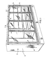
FIG. 1 depicts a refrigeration system employing the present invention. -
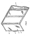
FIG. 2 . depicts a refrigeration door according to the present invention. -
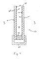
FIG. 3 is an illustration of a partial cross-sectional view of a refrigeration door according to the present invention. -
FIG. 4 is an illustration of a partial cross-sectional view of a refrigeration door according to the present invention. - In the following description, for purposes of explanation and not limitation, specific details are set forth, such as particular coatings, coating processes, sheet thicknesses, seal assemblies, number of sheets, sheet spacings, and methods for assembling the door, etc. in order to provide a thorough understanding of the present invention. However, it will be apparent to one skilled in the art that the present invention may be practiced in other embodiments that depart from these specific details. Detailed descriptions of well-known coatings, coating processes, sealant assemblies, and methods for assembling the door are omitted so as not to obscure the description of the present invention, For purposes of this description of the invention, terms such as external, internal, outer, and inner are descriptions from the perspective of the inside of the freezer or refrigerator compartment as is evident from the figures.
- Testing, as well as computer modeling, has shown that a U value (the conductivity of transfer of heat through the glass) of approximately 1.13 W/m2-K (0.2 BTU/hr-sq ft-F) is required for the refrigeration door to prevent condensation on the outside of the glass under the performance requirements for the United States industry as described above. As discussed, however, when the door is opened, condensation may form on the inside of the inner sheet of glass of the door because the temperature of the inner surface of the sheet is below the dew point of the more humid ambient store air to which it is exposed. The condensation, however, will dissipate once the door is closed as the moisture evaporates into the freezer or refrigerator compartment.
- While the condensation is present on the inside of the door, the contents of the freezer or refrigerator are not visible through the door. Consequently, the speed of the evaporation, which determines the length of time during which the condensation is present, is an important design criterion. The more heat that is transferred through the glass door to the inner surface of the glass door, the faster the condensation on the inside of the door will evaporate. However, increased heat transfer through the door also results in increased energy costs from the cooling system. Consequently, the optimal U value of the glass door will be driven by numerous factors including the difference between the outside and inside temperatures, the glass thickness, the spacing, the gas(es) used in the chamber(s) of the IGU, the number of sheets, the spacer material, the ambient humidity, the absorption coefficient of the coating in the far infrared spectrum, as well as the desirable time for evaporation of the condensation. In addition, the costs associated with the selected components (i.e., the gas, the sealant assembly, the glass, etc,), the energy costs, and other factors are also design considerations. The preferred embodiment described below provides a U value of 0.91 W/m2-K (0.16 BTU/hr-sq ft F) that prevents condensation on the outside of the door, while permitting enough heat to penetrate through the door from the ambient external environment to allow condensation on the inside of the door to evaporate in a reasonable amount of time. Some refrigeration system manufacturers require that the condensation evaporate within a few minutes and others require evaporation within one minute. The time required for the condensation to evaporate will vary according to the amount of time the door is open, the humidity in the store, the refrigeration system compartment temperature, the refrigeration system contents, the heat transferred through the door (which is dependent on the U value), and other factors.
- In the preferred embodiment of the present invention, as shown in
Figure 1 , a refrigeration system 5 includes a plurality oftransparent refrigeration doors 10 with each having a handle 11. As will be discussed in more detail below, eachrefrigeration door 10 includes anIGU 50 mounted in aframe 55. The interior of the refrigeration system includes a plurality of shelves 6 for holding merchandise to be seen through the door. Referring toFigure 2 , therefrigeration door 10 of the present embodiment is mounted to the opening of the refrigeration system with a hinge, which allows the door to open outwards. - As discussed above, the
refrigeration door 10 includes anIGU 50 housed in aframe 55. As shown inFigure 3 , theIGU 50 is comprised of an outer sheet ofglass 60, a middle sheet ofglass 65, and an inner sheet ofglass 70. TheIGU 50 is housed inframe 55 and also includes afirst sealant assembly 90 that extends around the periphery of theinner surface 62 of theouter sheet 60 and the outer surface of themiddle sheet 65 of glass to define a substantially hermetically sealed insulatedouter chamber 92. Similarly, asecond sealant assembly 95 extends around the periphery of theouter surface 72 of theinner sheet 70 and inner surface of themiddle sheet 65 of glass to define a substantially hermetically sealed insulatedinner chamber 94. - The
outer surface 61 of the outer sheet ofglass 60 is positioned adjacent the externalambient environment 7. In other words, theouter surface 61 of theouter sheet 60 is exposed to the environment in which the refrigerator or freezer resides. Theinner surface 62 of theouter sheet 60 forms part of, and is exposed to, theouter chamber 92. - In this preferred example embodiment, the
outer sheet 60 is 3.2 mm (one eighth of an inch) thick, tempered, and theinner surface 62 of theouter sheet 60 is coated with alow emissivity coating 63. Specifically, in this embodiment, the low E coating is a sputter-coated low E coating that includes an ultra-hard titania as the base layer to ensure a high level of thermal performance and a high visible transmittance. This particular sputter coated glass can be tempered after the coating and offers high visible light transmission without high levels of color tinting, Theouter surface 61 ofouter sheet 60 is not coated. In this embodiment, theouter sheet 60 may, for example, be a sheet of Comfort Ti-PS glass, 3.2 mm (one eighth of an inch) thick, manufactured by AFG Industries, Inc. of Kingsport, Tennessee, which has a low E coating providing an emissivity of 0.05. As is well-known in the art, the Comfort Ti-PS is cut to the appropriate size, tempered, and edged before being integrated into the IGU, 50. - The middle sheet of
glass 65 is positioned between the outer 60 and inner 70 sheets of glass and forms part of theouter chamber 92 and theinner chamber 94. Themiddle sheet 65 is space 12.7 mm (one half inch) from theouter sheet 60 andinner sheet 70 and is a 3.2 mm (one eighth of an inch) thick, uncoated, sheet of tempered glass - The inner sheet of
glass 70 is positioned adjacent the interior of the freezer or refrigeratingcompartment 9, with its inner surface 71 exposed to the interior of thecompartment 9. Theouter surface 72 of theinner sheet 70 forms part of, and is exposed to, theinner chamber 94. Theouter surface 72 of theinner sheet 70 of glass is also coated with alow emissivity coating 73, In this embodiment, thecoating 73 on theouter surface 72 of theinner sheet 70 is the same as that described above with respect to thecoating 63 of theinner surface 62 of theouter sheet 60. The inner surface 71 ofinner sheet 70 is not coated. In this embodiment, theinner sheet 70 may also, for example, be a sheet of Comfort Ti-PS, 3.2 mm (one eighth of an inch) thick, manufactured by AFG Industries, Inc., which has the described characteristics and coating. - In this example embodiment, the
chambers - The
sheets first sealant assembly 90 which extends around the periphery of thesheets relationship creating chamber 92 between thesheets chamber 92 from the external environment. Likewise, thesheets second sealant assembly 95 which extends around the periphery of thesheets relationship creating chamber 94 between thesheets chamber 94 from the external environment. Thesealant assemblies outer sheet 60 andmiddle sheet 65 andinner sheet 70 andmiddle sheet 65, respectively. - The
sealant assemblies sealant assemblies sealant assemblies - Referring to
Figure 3 ,IGU 50 is shown.IGU 50 is comprised ofglass sheets sealant assemblies IGU 50 is installed inframe 55 in any suitable manner well-known to those skilled in the art. Theframe 55 is made from extruded plastic or other suitable well-known frame materials, such as extruded aluminum, fiber glass or other material. If, in an alternative embodiment theframe 55 is formed of aluminum or other material, the door may require heating along its edges to ensure condensation control around the edges of the door, - Referring to
Figure 1 , a refrigeration system 5 is shown, Thedoor frame 55 is coupled to therefrigeration compartment 8 in any suitable fashion as is well known in the art, such as a single door long hinge, multiple hinges, or in a slot for sliding the door open and closed, In addition, the frame may include a door handle 11 or other suitable actuating means as is appropriate for the application. The refrigeration system 5, of which thedoor 10 forms a part, may be any system used for cooling a compartment, such as that disclosed inU.S. Pat. No, 6,148,563 . - The above preferred embodiment provides a refrigeration door with a U value of 0.91 w/m2-K (0.16 BTU/hr-sq ft-F) (and emissivity of 0.0025), which has been found to be suitable for freezer door applications requiring the performance standards identified above with respect to the United States industry. A U value of 0.91 W/m2-K (0.16 BTU/hr-sq ft-F) permits the refrigeration door to easily meet the required performance standards, while also allowing enough heat to penetrate through the door from the external ambient environment to evaporate condensation formed on the inside of the door in a reasonable time period, In addition, the preferred embodiment provides a visible light transmittance of sixty-six percent (66%).
- As an alternative to the Comfort Ti-PS glass, other low E coated glass may be used, such as, for example, Comfort Ti-R, Comfort Ti-AC, Comfort Ti-RTC, and Comfort Ti-ACTC, all of which are available from AFG Industries, Inc., which like Comfort Ti-PS, are titania/silver based low E coated glass manufactured by AFG Industries, Inc. Another suitable type of glass is Comfort E2, which is coated with a pyrolytic process and is a fluorine doped tin oxide low E coated glass 3.2 mm (one eighth of an inch) thick, and which is manufactured by AFG Industries, Inc. Comfort E2 is suitable for some of the less stringent performance standards because of its higher emissivity.
- The U value of the
refrigeration door 10 is determined by a number of design factors including the number of sheets of glass, the thickness of the sheets, the emissivity of the IGU, the spacing between the sheets, and the gas in the chamber(s). In the threepane refrigeration door 10 of the preferred embodiment described above, the U value of 0.91 W/m2-K (0.16 BTU/hr-sq ft-F) is accomplished using air as the gas being held in the chambers, glass thicknesses of 3.2 mm one eighth of an inch) on all sheets, 12.7 mm (one half inch) spacing, and an IGU emissivity of 0.0025. However, each of these factors can be varied resulting in numerous permutations of values that could be combined to provide the same U value. In addition, other applications may require a smaller or larger U value depending on the environment, costs constraints, and other requirements or considerations. - A number of computer simulations have been performed to determine the U values of numerous IGUs for use in
refrigeration doors 10 with a range of values of each of the various design parameters combined in different permutations, The table below includes the design parameters and corresponding calculated U values for a number of three pane IGU configurations. In addition to the design parameters listed in Table 1 below, all of the three pane IGU U value calculations were computed with each pane being 3.2 mm (one eighth of an inck) thick, and a total of two sides of the three panes being low E coated. Tempering of the glass does not significantly effect the calculated performance values.TABLE 1 Spacing between Sheets Gas in Chambers Type of Coating Emissivity of IGU U value mm Inches W/m2-K (Btu/hr -sq ft-F) 12.7 ½ air Ti-PS 0.0025 0.91 0.16 7.9 5/16 air Ti-PS 0.0025 1.25 0.22 12.7 ½ argon Ti-PS 0.0025 0.68 0.12 7.9 5/16 argon Ti-PS 0.0025 0.96 0.17 12.7 ½ krypton Ti-PS 0.0025 0.62 0.11 7.9 5/16 krypton Ti-PS 0.0025 0.62 0.11 12,7 ½ air CE2 0.04 1.13 0.20 7.9 5/16 air CE2 0.04 1.48 0.26 12.7 ½ argon CE2 0.04 0.96 0.17 7.9 5/16 argon CE2 0.04 1.19 0.21 12.7 ½ krypton CE2 0.04 0.85 0.15 7.9 5/16 krypton CE2 0.04 0.85 0.15 - In each of the tables included herein, "Ti-PS" refers to the low E coating of AFG Industries' Comfort Ti-PS glass and "CE2" refers to the low E coating of AFG Industries' Comfort E2 glass, both described above. In addition, the U values in the tables are calculated as "center of the glass" values, because the computer simulation does not have the capability to consider the sealant assembly. Consequently, there are no sealant assembly data or design criteria listed in the tables,
- In an alternative two pane embodiment of the present invention shown in
Figure 4 , theIGU 50 includes anouter sheet 60 andinner sheet 70 of glass, theframe 55, and asealant assembly 90. In this two-pane embodiment, both theouter sheet 60 andinner sheet 70 are 3.2 mm (one eighth of an inch) thick and include the same low E coating as described in the first embodiment, which is titania based silver low E coating. Again, both theouter sheet 60 andinner sheet 70 may, for example, be a sheet of Comfort Ti-FS glass 3.2 mm (one eighth of an inch) thick, manufactured by AFG Industries, Inc. The coated sides of thesheets chamber 92. In addition, thesame sealant assembly 90 described above (the Comfort Seal) may be used and acts to provide a spacing of 12.7 mm (one half inch) between the outer 60 and inner 70 sheets of glass. - Table 2 below includes design parameters and the corresponding calculated U values for a number of two pane IGUs. In addition to the design parameters listed in the table below, all of the two pane calculations were computed with each pane being 3.2 mm (one eighth of an inch) thick, and a total of two sides of the two panes being low E coated, Tempering of the glass does not significantly effect the calculated performance values.
TABLE 2 Spacing between Sheets Gas in Chambers Type of Coating Emissivity of IGU U value mm Inches W/m2-K (Btu/hr -sq ft-F) 12.7 ½ air Ti-PS 0.0025 1.65 0.29 7.9 5/16 air Ti-PS 0.0025 2.04 0.36 12.7 ½ argon Ti-PS 0.0025 1.31 0.23 7.9 5/16 argon Ti-PS 0.0025 1.59 0.28 12.7 ½ krypton Ti-PS 0.0025 1.25 0.22 7.9 5/16 krypton Ti-PS 0.0025 1.13 0.20 12.7 ½ air CE2 0.04 1.82 0.32 7.9 5/16 air CE2 0.04 2.21 0.39 12.7 ½ argon CE2 0.04 1.53 0.27 7.9 5/16 argon CE2 0.04 1.76 0.31 12.7 ½ krypton CE2 0.04 1.48 0.26 7.9 5/16 krypton CE2 0.04 1.36 0.24 - In alternative embodiments, any suitable type of coating processes may be employed including pyrolytic (e.g., as in the Comfort E2), which is often referred to as chemical vapor deposition (CVD), spray, and sputter coating (e.g., as in the Comfort Ti-PS). Furthermore, these processes may be applied using well-known off-line or on-line manufacturing methods as is suitable and appropriate for the quantity and type of production and process. Likewise, any suitable low E coating may be employed including silver based, titania based, or fluorine doped tin oxide coating.
- Although the embodiments described above include low E coatings on the unexposed surfaces of two sheets of glass, other embodiments of the present invention might include a low E coating applied to only one sheet of glass on either side, or on both sides. Likewise, in other embodiments the middle sheet of glass (of a three pane embodiment) may include a low E coating on either side (or both sides) instead of, or in addition to, coatings on the
inner sheet 70 andouter sheet 60 of glass. - In yet another three pane embodiment, the inner sheet of
glass 70 does not have a low E coating on either side of the sheet ofglass 70. Likewise, in an alternative to the two sheet embodiment described above, the low E coating is present on only one sheet, or on both sides of both sheets. In general, the number of sheets that have the low E coating and the side (or sides) that have the coating is a design choice. The total emissivity of the IGU, which along with other factors determines the U factor of the door, is more important with respect to the thermal performance than which side or sides of which sheet(s) are coated. In addition, although the embodiments described herein have emissivities of less than or equal to 0.04 for refrigeration door applications, using a high performance gas (such as krypton) may enable an IGU with an emissivity of slightly more than 0.04 to provide the necessary condensation control in some circumstances. - In other embodiments, other sealant assemblies may be employed including for example, an all-foam, non-metal assembly such as the Super Spacer, manufactured by EdgeTech, Inc, which has a heat transfer rate of approximately 1.51 Btu/hr-ft-F. Another suitable sealant assembly is the ThermoPlastic Spacersystem (TPS) manufactured by Lenhardt Maschinenbau GmbH, which has a heat transfer rate of approximately 2.61 W/m-K (1.73 Btu/hr-ft-F).
- The spacing in the above disclosed embodiments is 12.7 mm (one half inch). However, while the preferred spacing ranges between 7.9 mm (five sixteenths of an inch) to 12.7 mm (one half inch), other embodiments of the invention may use spacings up to 19.0 mm (three quarters of an inch). In addition, while the above disclosed embodiments employ glass 3.2 mm (one eighth of an inch) thick that is tempered (except for the middle sheet), other embodiments may use untempered glass or thicknesses that are greater than, or less than 3.2 mm (one eighth of an inch).
- The design parameters of an embodiment of the present invention will be determined, in part, by the application or intended use of the embodiment. More specifically, the exterior ambient temperature, interior temperature, and exterior ambient humidity (and associated dew point) are important factors in determining the necessary U value for the design, which in turn, determines the design parameters (type of glass, emissivity, number of sheets, gas, etc.).
- The left five columns of Table 3 below provide a list of calculated U values for various applications of the intended use and includes the exterior temperature, interior temperature, exterior humidity, and calculated dew point for each U value. In addition, the right three columns of Table 3 provide an embodiment of the invention that will provide the necessary U value,
TABLE 3 Calculated U Values for Various Environmental Parameter IGU Design Variables for Satisfying Identified U Value Exterior Temp Interior Temp U Value Dewpoint (Outside Glass T) Maximum Relative Humidity Percent Glass (Two Sheets) Spacing Gas In Chambers °C °F °C °F W/m2 -K Btu/ hr-sq ft-F °C °F mm Inches 26.7 80 -40.0 -40 1.08 0.19 18.3 64.9 60.1 Ti-PS 9.5 3/8 air 22.2 72 -17.8 0 1.53 0.27 14.1 57.4 60 CE2 7.9 5/16 air 26.7 80 -40.0 -40 0.85 0.15 19.8 67.6 66.0 CE2 9.5 3/8 krypton 26.7 80 -40.0 -40 1.02 0.18 18.7 65.7 61.8 CE2 9.5 3/8 argon 26.7 80 -40.0 -40 1.42 0.25 15.7 60.3 51.1 CE2 9.5 3/8 air 26.7 80 -40.0 -40 0.91 0.16 19.6 67.3 65.3 CE2 9.5 1/2 krypton 26.7 80 -40,0 -40 0.96 0.17 19.2 66.5 63.5 CE2 12,7 1/2 argon 26.7 80 -40.0 -40 1.13 0.20 17.8 64.1 58.5 CE2 12.7 1/2 air 26.7 80 -40.0 -40 0.62 0.11 21.4 70.6 73.1 Ti-PS 9.5 3/8 krypton 26.7 80 -40.0 -40 0.79 0.14 20.3 68.6 68.3 Ti-PS 9.5 3/8 argon 26.7 80 -40.0 -40 1.08 0.19 18.3 65.0 60.3 Ti-PS 9.5 3/8 air 26.7 80 -40.0 -40 0.68 0.12 21.2 70.2 72.1 Ti-PS 12.7 1/2 krypton 26.7 80 -40.0 -40 0.74 0.13 20.8 69.4 70.2 Ti-PS 12.7 1/2 argon 26.7 80 -40.0 -40 0.96 0.17 19.3 66.7 64.0 Ti-PS 12.7 1/2 air 22.2 72 -23.3 -10 1.02 0.18 16.2 61.2 68.9 CE2 9.5 3/8 argon 22.2 72 -17.8 0 1.02 0.18 16.7 62.1 71.1 CE2 9.5 3/8 argon 22.2 72 -12.2 10 1.02 0.18 17.2 63.0 73.4 CE2 9.5 3/8 argon 21.1 70 -17.8 0 1.02 0.18 15.7 60.3 71.4 CE2 9.5 3/8 argon 26.7 80 -17.8 0 1.02 0.18 20.7 69.2 69.7 CE2 9.5 3/8 argon 32.2 90 -17.8 0 1.02 0.18 25.6 78.1 68.3 CE2 9.5 3/8 argon 21.1 70 -28.9 -20 1.19 0.21 13.1 55.5 60.1 CE2 9.5 3/8 air 30.0 86 30.0 -22 0.62 0.11 25.3 77.5 75.9 Ti-PS 9.5 3/8 krypton 26.7 80 40.0 -40 1.08 0.19 18.3 65.0 60.3 CE1 12.7 1/2 air 21.1 70 0.0 32 1.02 0.18 17.4 63.4 79.6 CE2 9.5 3/8 argon 26.7 80 0.0 32 1.02 0.18 22.3 72.2 77.2 CE2 9.5 3/8 argon 32.2 90 0.0 32 1.02 0.18 27.2 81.0 75.0 CE2 9.5 3/8 argon - The design parameters of Table 3 identify the type of glass (which is 3.2 mm (one eighth of an inch) thick), the spacing between sheets, and the gas in the chambers. In addition, all of the IGUs of the Table 3 include a third, non-coated sheet of glass that is 3.2 mm (one eighth of an inch) thick, and that is disposed between the two sheets of glass identified in the table, CE1 in the Table 3 refers to Comfort E1, which has an emissivity of 0,35 and is sold by AFG Industries, Inc.
- The foregoing has described the principles, embodiments, and modes of operation of the present invention. However, the invention should not be construed as being limited to the particular embodiments described above, as they should be regarded as being illustrative and not as restrictive. It should be appreciated that variations may be made in those embodiments by those skilled in the art without departing from the scope of the present invention according to the appended claims.
- While the application of the present invention has been described in the application of a refrigerator or freezer door, other applications might include vending machines, skylights, or refrigerated trucks. In some of these applications, condensation on the second or colder side of the glass may not be an issue because the glass is not in a door that is periodically opened exposing the cold glass to a more humid environment. As a result, the key factors in designing the glass are economics (i.e., the energy costs and the cost of the glass and its installation), visible transmittance, durability, and other considerations.
- While a preferred embodiment of the present invention has been described above, it should be understood that it has been presented by way of example only, and not limitation. Thus, the breadth and scope of the present invention should not be limited by the above described exemplary embodiment.
- Obviously, numerous modifications and variations of the present invention are possible in light of the above teachings. It is therefore to be understood that within the scope of the appended claims, the invention may be practiced otherwise than as specifically described herein.
Claims (67)
- A refrigeration door (10) having an outer surface (61) and adapted to be mounted on a refrigerating compartment, said door comprising:a first sheet of glass (70);a second sheet of glass (60, 65);a first sealant assembly (90, 95) disposed around the periphery of said first sheet of glass (70) and said second sheet of glass (60, 65) for maintaining said first sheet and said second sheet in spaced-apart relationship from each other;a first low emissivity coating (63, 73) adjacent a surface of said first sheet or said second sheet of glass; anda frame secured around the periphery of said insulating glass unit, wherein said first sealant assembly is a non-metal assemblycharacterised in that said first sheet and second sheets of glass (60, 65, 70), said first sealant assembly (90, 95), and said first low emissivity coating (63, 73) form an insulating glass unit (50) having a U value substantially equal to or less than 1.13 W/m2-K (0.2 BTU/hr-sq ft-F) or an emissivity substantially equal to or less than 0.04, wherein said U-value or said emissivity is effective to substantially prevent the formation of condensation on the outer surface of the door without the applicaton of electricity for heating the outer surface;.
- The refrigeration door of claim 1, further comprising:a third sheet of glass (60);a second sealant assembly (90) disposed around the periphery of said second sheet of glass (65) and said third sheet of glass (60) for maintaining said second sheet and said third sheet in spaced-apart relationship from each other; andwherein said said second sealant assembly (90) is a non-metal assembly.
- The refrigeration door of claim 2, further including a second low emissivity coating (63, 73) adjacent a surface of said first sheet, said second sheet, or said third sheet of glass (60, 65, 70).
- The refrigeration door of claim 3, wherein the U value of said insulating glass unit is effective to substantially prevent the formation of condensation on the outer surface (61) of the door (10) without the application of electricity for heating the outer surface when the interior temperature of the refrigerating compartment (9) is substantially equal to or less than -17.8°C (zero degrees Fahrenheit); the temperature of the exterior environment (7) is substantially equal to or greater than 22.2°C (seventy-two degrees Fahrenheit); and the humidity in the ambient environment is substantially equal to or greater than sixty percent.
- The refrigeration door of claim 1, wherein the U value of said insulating glass unit is effective to substantially prevent the formation of condensation on the outer surface (61) of the door (10) without the application of electricity for heating the outer surface when the interior temperature of the refrigerating compartment (9) is substantially equal to or less than -17.8°C (zero degrees Fahrenheit); the temperature of the exterior environment (7) is substantially equal to or greater than 22.2°C (seventy-two degrees Fahrenheit); and the humidity in the ambient environment is substantially equal to or greater than sixty percent.
- The refrigeration door of claim 5, further comprising:a first chamber (92, 94) defined by said first sheet of glass (70), said second sheet of glass (60, 65), and said first sealant assembly (90, 95); anda gas disposed in said first chamber.
- The refrigeration door of claim 6, wherein said first sealant assembly has a heat transfer rate substantially equal to or less than 2.99 W/m-K (1.73 Btu/hr-ft-F).
- The refrigeration door of claim 6, wherein said gas is selected from the group consisting of argon, krypton, and air.
- The refrigeration door of claim 1, wherein said insulating glass unit has a U value substantially equal to or less than 0.91 W/m2-K (0.16 BTU/hr-sq ft-F).
- The refrigeration door of claim 1, wherein said insulating glass unit has an emissivity substantially equal to or less than 0.01.
- The refrigeration door of claim 1, wherein insulating glass unit has an emissivity substantially equal to or less than 0.0025.
- The refrigeration door of claim 1, wherein the interior temperature of the refrigerating compartment is substantially equal to or less than -28.9°C (minus twenty degrees Fahrenheit); the temperature of the exterior environment (7) is substantially equal to or greater than 21.1°C (seventy degrees Fahrenheit); and the humidity in the exterior environment (7) is substantially equal to or greater than sixty percent; and wherein the outer surface (61) of the door is substantially free of condensation.
- The refrigeration door of claim 1, wherein the interior temperature of the refrigerating compartment (9) is substantially equal to or less than -40°C (minus forty degrees Fahrenheit); the temperature of the exterior environment (7) is substantially equal to or greater than 26.7°C (eighty degrees Fahrenheit); and the humidity in the exterior environment (7) is substantially equal to or greater than sixty percent; and wherein the outer surface of the door is substantially free of condensation.
- The refrigeration door of Claim 3 or any of Claims 4 to 13, wherein:the first sheet of glass (70) is an inner sheet of glass including a first surface (71) and a second surface (72), said first surface (71) of said inner sheet being disposed adjacent the interior of the refrigerating compartment (9);the third sheet of glass (60) is an outer sheet of glass including a first surface (61) and a second surface (62), said first surface (61) of said outer sheet being disposed adjacent the exterior environment (7) of the refrigerating compartment;the second sheet of glass (65) is a middle sheet of glass disposed between said inner and outer sheets of glass,the first sealant assembly (95) being disposed around the periphery of said inner sheet of glass (70) and said middle sheet of glass (65) for maintaining said inner sheet and said middle sheet in spaced-apart relationship from each other;the second sealant assembly (90) being disposed around the periphery of said middle sheet of glass (65) and said outer sheet of glass (60) for maintaining said middle sheet and said outer sheet in spaced-apart relationship from each other;the first low emissivity coating (73) being adjacent the second surface (72) of said inner sheet of glass (70);the second low emissivity coating (63) being adjacent the second surface (62) of said outer sheet of glass (60);said inner sheet (70), outer sheet (60), middle sheet (65), first sealant assembly (95), second sealant assembly (90), and said first and second low emissivity coatings (63, 73) forming the insulating glass unit (50) having a U value substantially equal to or less than 1.13 W/m2-K (0.2 BTU/hr-sq ft-F) or an emissivity substantially equal to or less than 0.04, substantially preventing the formation of condensation on said first surface of said outer sheet of glass without the application of electricity for heating said first surface of said outer sheet of glass.
- The refrigeration door of claim 14, further comprising:a first chamber (94) defined by said inner sheet of glass (70), said middle sheet of glass (65), and said first sealant assembly (95);a second chamber (92) defined by said middle sheet of glass (65), said outer sheet of glass (60), and said second sealant assembly (90); anda gas disposed in said first and second chambers.
- The refrigeration door of claim 15, wherein:said inner (70), said middle (65), and said outer sheets (65) of glass have a thickness substantially equal to 3.2 mm (one eighth of an inch);said inner and said middle sheets of glass being spaced apart a distance substantially equal to 12.7 mm (one half inch); andsaid middle and said outer sheets of glass being spaced apart a distance substantially equal to 12.7 mm (one half inch).
- The refrigeration door of claim 15, wherein said first sealant assembly (95) and said second sealant assembly (90) each have a heat transfer rate substantially equal to or less than 2.99 W/m-K (1.73 Btu/hr-ft-F).
- The refrigeration door of claim 17, wherein:said inner (70), said middle (65) and said outer sheets (65) of glass having a thickness substantially equal to 3.2 mm (one eighth of an inch);said inner (70) and said middle sheets (65) of glass being spaced apart a distance substantially equal to 12.7 mm (one half inch); andsaid middle (65) and said outer sheets (60) of glass being spaced apart a distance substantially equal to 12.7 mm (one half inch).
- The refrigeration door of claim 15, wherein said gas in said first chamber (94) and said second chamber (92) are the same.
- The refrigeration door of claim 15, wherein said gas in said first chamber (94) and said second chamber (92) are not the same.
- The refrigeration door of claim 15, wherein said outer sheet (60) and said inner sheet (70) each have an emissivity substantially equal to or less than 0.05.
- The refrigeration door of claim 15, wherein said outer sheet (60) and said inner sheet (70) each have an emissivity substantially equal to or less than 0.03.
- The refrigeration door of claim 15, wherein said first and second low emissivity coatings (73, 63) are selected from the group consisting of a titania based silver and fluorine doped tin oxide.
- The refrigeration door of claim 15, wherein said first and second low emissivily coatings (73, 63) are applied with a process selected from the group consisting of sputter coating, pyrolytic coating and spray coating.
- The refrigeration door of claim 15, wherein said frame (55) is formed from a material selected from the group consisting of extruded plastic, aluminum, and fiber glass.
- The refrigeration door of claim 14, wherein said first sealant assembly (95) and said second sealant assembly (90) each have a heat transfer rate substantially equal to or less than 2.99 W/m-K (1.73 Btu/hr-ft-F).
- The refrigeration door of claim 14, wherein said first sealant assembly (95) and said second sealant assembly (90) each have a heat transfer rate substantially equal to or less than 2.61 W/m-K (1.51 Btu/hr-ft-F).
- The refrigeration door of claim 14, wherein said first sealant assembly (95) and said second sealant assembly (90) each have a heat transfer rate substantially equal to or less than 1.45 W/m-K (0.84 Btu/hr-ft-F).
- The refrigeration door (10) of claim 3 wherein the insulating glass unit (50) has a U value that substantially prevents the formation condensation on the outer surface (61) when the interior temperature of the refrigerating compartment (9) is substantially equal to or less than -40°C (minus forty degrees Fahrenheit); the temperature of the exterior environment (7) is at substantially equal to or greater than 26.7°C (eighty degrees Fahrenheit); and the humidity In the exterior environment (7) is substantially equal to or greater than sixty percent.
- The refrigeration door of claim 2, wherein said first sealant assembly (95) and said second sealant assembly (90) each have a heat transfer rate substantially equal to or less than 2.99 W/m-K (1.73 Btu/hr-ft-F).
- The refrigeration door of claim 1, wherein said first sheet (70) or second sheet (60, 65) has an emissivity substantially equal to or less than 0.05.
- The refrigeration door of claim 1, wherein said first sealant assembly (90, 95) is a composite extrusion comprising a combination of polyisobutylene sealant, hot melt butyl sealant, desiccant matrix, rubber shim, and a vapor barrier.
- The refrigeration door of claim 2, wherein said second sealant assembly (90) is a composite extrusion comprising a combination of polyisobutylene sealant, hot melt butyl sealant, desiccant matrix, rubber shim, and a vapor barrier.
- The refrigeration door of claim 1, wherein said first sealant assembly (90, 95) is an all-foam assembly.
- The refrigeration door of claim 1, wherein said first sealant assembly (90, 95) is a warm edge seal.
- The refrigeration door of claim 2, wherein said second sealant assembly (90) is an all-foam assembly.
- The refrigeration door of claim 2, wherein said second sealant assembly (90) is a warm edge seal.
- A refrigeration unit including an insulated enclosure defining a compartment (9), a cooling system, and a refrigeration door (10) as described in any of Claims 1 to 28 adapted to be mounted on an opening of said compartment.
- The refrigeration unit of claim 38, wherein said first sealant assembly (90, 95) is a composite extrusion comprising a combination of polyisobutylene sealant, hot melt butyl sealant, desiccant matrix, rubber shim, and a vapor barrier.
- The refrigeration unit of claim 38, the refrigeration unit comprising a refrigeration door (10) as described in Claim 2, wherein said second sealant assembly (90) is a composite extrusion comprising a combination of polylsobutylene sealant, hot melt butyl sealant, desiccant matrix, rubber shim, and a vapor barrier.
- The refrigeration unit of claim 38, wherein said first sealant assembly (90, 95) is an all-foam assembly,
- The refrigeration unit of claim 38, wherein said first sealant assembly (90, 95) is a warm edge seal.
- The refrigeration unit of claim 38, the refrigeration unit comprising a refrigeration door (10) as described in Claim 2, wherein said second sealant assembly (90) is an all-foam assembly.
- The refrigeration unit of claim 38, the refrigeration unit comprising a refrigeration door (10) as described in Claim 2, wherein said second sealant assembly (90) is a warm edge seal.
- A method of manufacturing a refrigeration door component having an outer surface, said method comprising the steps of:providing a first sheet of glass (70);providing a second sheet of glass (60, 65);providing a first low emissivity coating (73, 63) adjacent a surface (72, 52) of said first sheet t of glass or said second sheet of glass (70, 60, 65);disposing a first sealant assembly (90, 95) around the periphery of said first sheet of glass (70) and said second sheet of glass (60, 65) to maintain said first sheet and said second sheet in spaced-apart relationship from each other; and wherein said first sealant assembly is a non-metal assembly;characterised in that said first sheet of glass (70), said second sheet of glass (60, 65), and said first sealant assembly (90, 95) form an insulating glass unit having a U value substantially equal to or less than 1.13 W/m2-K (0.2 BTU/hr-sq ft-F) or an emissivity substantially equal to or less than 0.04 substantially preventing the formation of condensation on the outer surface of the refrigeration door component without the application of electricity for heating the door component.
- The method of claim 45, wherein said first sheet of glass (70), said second sheet of glass (60, 65), and said first sealant assembly (90, 95) define a first chamber (92, 94); and further comprising the step of disposing a gas in said first chamber.
- The method of claim 45, further comprising the steps of:providing a third sheet of glass (60);disposing a second sealant assembly (90) disposed around the periphery of said second sheet of glass (65) and said third of glass (60) for maintaining said second sheet and said third sheet in spaced-apart relationship from each other; andwherein said insulating glass unit (50) further includes said third sheet of glass (60) and said second sealant assembly (90), and wherein said second sealant assembly is a non-metal assembly.
- The method of claim 47, wherein said third sheet of glass (60) includes a low emissivity coating (63) adjacent a surface (62) of said third sheet of glass.
- The method of claim 45, wherein said first sealant assembly (90, 95)has a heat transfer rate substantially equal to or less than 2.99 W/m-K (1.73 Btu/hr-ft-F).
- The method of claim 49, wherein:said first (70) and said second sheets (60, 65) of glass having a thickness substantially equal to 3.2 mm (one eighth of an inch); andsaid first (70) and said second sheets (60, 65) of glass being spaced apart a distance substantially equal to 12,7 mm (one half inch).
- The method of claim 45, further including the step of disposing said insulating glass unit (50) in a door frame (55).
- The method of claim 46, wherein said gas is selected from the group consisting of argon, krypton, and air.
- The method of claim 45, wherein said insulating glass unit has a U value substantially equal to or less than 0.91 W/m2-K (0.16 BTU/hr-sq ft-F).
- The method of claim 45, wherein said insulating glass unit has an emissivity substantially equal to or less than 0.01.
- The method of claim 45, wherein said insulating glass unit has an emissivity substantially equal to or less than 0.0025.
- The method of claim 45, wherein said low emissivity coating (63, 73) is selected from the group consisting of a titania based silver and fluorine doped tin oxide.
- The method of claim 45, wherein said low emissivity coating (63, 73) is applied with a process selected from the group consisting of sputter coating, pyrolytic coating and spray coating.
- The method of claim 47, wherein said first (95) and second (90) sealant assemblies have a heat transfer rate substantially equal to or less than 2.99 W/m-K (1.73 Btu/hr-ft-F).
- The method of claim 45, wherein said first sealant assembly (90, 95) has a heat transfer rate substantially equal to or less than 2.61 W/m-K (1.51 Btu/hr-ft-F).
- The method of claim 45, wherein said first sealant assembly (90, 95) has a heat transfer rate substantially equal to or less than 1.45 W/m-K (0.84 Btu/hr-ft-F).
- The method of claim 47, further including the step of disposing said insulating glass unit in a door frame (55).
- The method of claim 45, wherein said first sealant assembly (90, 95) is a composite extrusion comprising a combination of polyisobutylene sealant, hot melt butyl sealant, desiccant matrix, rubber shim, and a vapor barrier.
- The method of claim 47, wherein said second sealant assembly (90) is a composite extrusion comprising a combination of polyisobutylene sealant, hot melt butyl sealant, desiccant matrix, rubber shim, and a vapor barrier.
- The method of claim 45, wherein said first sealant assembly (90, 95) is an all-foam assembly.
- The method of claim 45, wherein said first sealant assembly(90, 95) is a warm edge seal.
- The method of claim 47, wherein said second sealant assembly (90) is an all-foam assembly.
- The method of claim 47, wherein said second sealant assembly (90) is a warm edge seal.
Applications Claiming Priority (3)
| Application Number | Priority Date | Filing Date | Title |
|---|---|---|---|
| US909262 | 2001-07-19 | ||
| US09/909,262 US20030062813A1 (en) | 2001-07-19 | 2001-07-19 | Energy-free refrigeration door and method for making the same |
| PCT/US2002/022653 WO2003008877A2 (en) | 2001-07-19 | 2002-07-17 | Energy-free refrigeration door and method for making the same |
Publications (3)
| Publication Number | Publication Date |
|---|---|
| EP1421321A2 EP1421321A2 (en) | 2004-05-26 |
| EP1421321A4 EP1421321A4 (en) | 2006-09-13 |
| EP1421321B1 true EP1421321B1 (en) | 2009-12-23 |
Family
ID=25426915
Family Applications (1)
| Application Number | Title | Priority Date | Filing Date |
|---|---|---|---|
| EP02756503A Revoked EP1421321B1 (en) | 2001-07-19 | 2002-07-17 | Energy-free refrigeration door and method for making the same |
Country Status (12)
| Country | Link |
|---|---|
| US (4) | US20030062813A1 (en) |
| EP (1) | EP1421321B1 (en) |
| JP (5) | JP2004538434A (en) |
| CN (1) | CN1556680B (en) |
| AT (1) | ATE453092T1 (en) |
| AU (1) | AU2002322509A1 (en) |
| CA (1) | CA2454180A1 (en) |
| DE (1) | DE60234841D1 (en) |
| ES (1) | ES2338998T3 (en) |
| MX (1) | MXPA04000576A (en) |
| PT (1) | PT1421321E (en) |
| WO (1) | WO2003008877A2 (en) |
Families Citing this family (78)
| Publication number | Priority date | Publication date | Assignee | Title |
|---|---|---|---|---|
| US7976916B2 (en) | 1999-05-25 | 2011-07-12 | Saint-Gobain Vitrage | Refrigerated display case having a transparent insulating glazing unit |
| FR2794225B3 (en) * | 1999-05-25 | 2001-06-15 | Saint Gobain Vitrage | REFRIGERATED ENCLOSURE DOOR WITH VACUUM WINDOWS |
| US20060103269A1 (en) * | 2004-07-23 | 2006-05-18 | Anthony, Inc. | Soft-coated glass pane refrigerator door construction and method of making same |
| US7856770B2 (en) * | 2004-08-31 | 2010-12-28 | Hussmann Corporation | Multi-pane glass assembly for a refrigerated display case |
| SG155934A1 (en) * | 2004-09-20 | 2009-10-29 | Agc Flat Glass North America | Anti-fog refrigeration door and method of making the same |
| DE202004019865U1 (en) * | 2004-11-29 | 2006-04-06 | Liebherr-Hausgeräte Lienz Gmbh | Fridge and / or freezer |
| EP1879480B1 (en) * | 2005-04-28 | 2013-03-20 | Carrier Corporation | Frameless door suspension |
| SG165390A1 (en) * | 2005-09-20 | 2010-10-28 | Agc Flat Glass Na Inc | Anti-fog refrigeration door and method of making the same |
| US20090072679A1 (en) * | 2006-03-16 | 2009-03-19 | Carrier Corporation | Glass door for refrigerated merchandiser |
| ITPN20060059A1 (en) * | 2006-08-04 | 2008-02-05 | Electrolux Professional Spa | COOKING OVEN WITH ANTI-CONDENSATE DOOR |
| US20080190941A1 (en) * | 2007-01-19 | 2008-08-14 | Metro Industries Inc. | Food Service Cabinet With Nanomaterial Coating |
| CA2695773A1 (en) * | 2007-08-24 | 2009-03-05 | Weather Shield Mfg., Inc. | Windows, doors and glazing assemblies therefor |
| JP5310019B2 (en) * | 2008-05-28 | 2013-10-09 | セントラル硝子株式会社 | Double glazing |
| WO2010010156A1 (en) | 2008-07-24 | 2010-01-28 | Agc Flat Glass Europe Sa | Insulating multiple glazing |
| USD612517S1 (en) | 2008-08-20 | 2010-03-23 | Anthony, Inc. | Door |
| US8613161B2 (en) * | 2008-08-20 | 2013-12-24 | Anthony, Inc. | Refrigerator door construction including a laminated package |
| JP5424059B2 (en) * | 2009-09-15 | 2014-02-26 | 旭硝子株式会社 | Multi-layer glass structure and cold insulation showcase |
| US9289079B2 (en) | 2009-11-05 | 2016-03-22 | Hussmann Corporation | Door for a refrigerated merchandiser |
| US8304045B2 (en) | 2010-02-26 | 2012-11-06 | Guardian Industries Corp. | Articles including anticondensation coatings and/or methods of making the same |
| US8524337B2 (en) | 2010-02-26 | 2013-09-03 | Guardian Industries Corp. | Heat treated coated article having glass substrate(s) and indium-tin-oxide (ITO) inclusive coating |
| IT1404030B1 (en) * | 2010-07-15 | 2013-11-08 | Mondial Group Srl | INSULATED GLASS DOOR, PERFECTLY FOR REFRIGERANT APPLIANCES. |
| US20120090246A1 (en) * | 2010-10-15 | 2012-04-19 | Guardian Industries Corp. | Refrigerator/freezer door, and/or method of making the same |
| JP5488837B2 (en) * | 2011-03-04 | 2014-05-14 | 旭硝子株式会社 | MULTILAYER GLASS STRUCTURE, COOLING SHOWCASE DOOR AND METHOD FOR MEASURING INert GAS CONCENTRATION OF MULTILAYER GLASS STRUCTURE |
| FR2978525B1 (en) | 2011-07-29 | 2018-05-18 | Saint-Gobain Glass France | LUMINOUS MULTIPLE FURNITURE GLAZING |
| CN102411809A (en) * | 2011-08-28 | 2012-04-11 | 陈太明 | Novel energy-saving automatic vending machine |
| US9881528B2 (en) | 2011-10-13 | 2018-01-30 | Manufacturing Resources International, Inc. | Transparent liquid crystal display on display case |
| US8695362B2 (en) | 2012-01-19 | 2014-04-15 | Hussmann Corporation | Refrigerated merchandiser with door having boundary layer |
| NL1039440C2 (en) * | 2012-03-06 | 2013-09-09 | Polyplastic Groep B V | COOLING DEVICE AND ACCESS DOOR. |
| US8869493B2 (en) * | 2012-03-14 | 2014-10-28 | Thermoseal Industries, L.L.C. | Door for a refrigerated cabinet |
| US9332862B2 (en) * | 2012-11-30 | 2016-05-10 | Guardian Industries Corp. | Refrigerator door/window |
| US20140265758A1 (en) * | 2013-03-13 | 2014-09-18 | Hussmann Corporation | Three side silver frit on heated glass |
| US20160073792A1 (en) * | 2013-04-26 | 2016-03-17 | Doors, Covers & More B.V. | Double-walled acrylic door for refrigerated cabinets |
| CN105283099A (en) * | 2013-06-14 | 2016-01-27 | 旭硝子欧洲玻璃公司 | Glass element for a cabinet having a refrigerated chamber |
| CN104089452B (en) * | 2013-09-17 | 2017-01-18 | 广东富信科技股份有限公司 | Semi-conductor refrigerating cabinet |
| US10165870B2 (en) | 2014-02-11 | 2019-01-01 | Anthony, Inc. | Display case door assembly with vacuum panel |
| US9498072B2 (en) | 2014-02-11 | 2016-11-22 | Anthony, Inc. | Display case door assembly with tempered glass vacuum panel |
| BR112016019713B1 (en) * | 2014-03-07 | 2022-01-18 | Agc Glass Europe | INSULATING GLASS ELEMENT, REFRIGERATED CHAMBER FURNITURE AND BUILDING WINDOW |
| CA2952619C (en) * | 2014-06-16 | 2019-04-16 | Manufacturing Resources International, Inc. | Transparent lcd assembly with display case |
| US9500896B2 (en) | 2014-06-16 | 2016-11-22 | Manufacturing Resources International, Inc. | Cooling system for liquid crystal display |
| US9633366B2 (en) | 2014-06-16 | 2017-04-25 | Manufacturing Resources International, Inc. | System for tracking and analyzing display case usage |
| US9526353B2 (en) * | 2014-07-22 | 2016-12-27 | Richard Chubb | Door for a freezer cabinet |
| JP2016056064A (en) * | 2014-09-10 | 2016-04-21 | 旭硝子株式会社 | Multilayer glass |
| US10649273B2 (en) | 2014-10-08 | 2020-05-12 | Manufacturing Resources International, Inc. | LED assembly for transparent liquid crystal display and static graphic |
| US9832847B2 (en) | 2014-10-09 | 2017-11-28 | Manufacturing Resources International, Inc. | System for decreasing energy usage of a transparent LCD display case |
| US10182665B2 (en) | 2014-10-15 | 2019-01-22 | Manufacturing Resources International, Inc. | System and method for preventing damage to products |
| US9955803B2 (en) | 2014-12-15 | 2018-05-01 | Hussmann Corporation | Door for a refrigerated merchandiser |
| WO2016170079A1 (en) | 2015-04-22 | 2016-10-27 | Saint-Gobain Glass France | Method and device for producing a triple insulated glazing |
| KR102529853B1 (en) | 2015-08-03 | 2023-05-08 | 엘지전자 주식회사 | Vacuum adiabatic body, fabricating method for the Vacuum adiabatic body, porous substance package, and refrigerator |
| KR102498210B1 (en) | 2015-08-03 | 2023-02-09 | 엘지전자 주식회사 | Vacuum adiabatic body and refrigerator |
| KR102466469B1 (en) | 2015-08-03 | 2022-11-11 | 엘지전자 주식회사 | Vacuum adiabatic body and refrigerator |
| KR102525550B1 (en) | 2015-08-03 | 2023-04-25 | 엘지전자 주식회사 | Vacuum adiabatic body and refrigerator |
| KR102442973B1 (en) | 2015-08-03 | 2022-09-14 | 엘지전자 주식회사 | Vacuum adiabatic body and refrigerator |
| KR102456642B1 (en) | 2015-08-03 | 2022-10-19 | 엘지전자 주식회사 | Vacuum adiabatic body and refrigerator |
| KR20170016188A (en) | 2015-08-03 | 2017-02-13 | 엘지전자 주식회사 | Vacuum adiabatic body and refrigerator |
| KR102529852B1 (en) | 2015-08-03 | 2023-05-08 | 엘지전자 주식회사 | Vacuum adiabatic body and refrigerator |
| KR102525551B1 (en) | 2015-08-03 | 2023-04-25 | 엘지전자 주식회사 | Vacuum adiabatic body and refrigerator |
| KR102447245B1 (en) | 2015-08-03 | 2022-09-27 | 엘지전자 주식회사 | Vacuum adiabatic body and refrigerator |
| WO2017023094A1 (en) | 2015-08-03 | 2017-02-09 | Lg Electronics Inc. | Vacuum adiabatic body and refrigerator |
| KR102502160B1 (en) | 2015-08-03 | 2023-02-21 | 엘지전자 주식회사 | Vacuum adiabatic body and refrigerator |
| KR102466470B1 (en) | 2015-08-04 | 2022-11-11 | 엘지전자 주식회사 | Vacuum adiabatic body and refrigerator |
| CA3014922A1 (en) * | 2016-03-02 | 2017-09-08 | Anthony, Inc. | Display case door assembly with tempered glass vacuum panel |
| DE102016110505A1 (en) | 2016-06-07 | 2017-12-07 | Boje Martens | Illuminated glass and process for its manufacture |
| DE202016103026U1 (en) | 2016-06-07 | 2016-07-22 | Boje Martens | Illuminated glass pane |
| CN106158050A (en) * | 2016-06-29 | 2016-11-23 | 中国科学院国家天文台 | A kind of thermal protection structure for nearly sun observation equipment |
| AU2017293369B2 (en) | 2016-07-08 | 2019-11-28 | Manufacturing Resources International, Inc. | Mirror having an integrated electronic display |
| CN106679302A (en) * | 2017-02-22 | 2017-05-17 | 合肥舒实工贸有限公司 | Refrigerator door body |
| CN107217958A (en) * | 2017-05-23 | 2017-09-29 | 句容耀皮节能玻璃科技发展有限公司 | A kind of double layer hollow energy-saving glass |
| US10575660B2 (en) * | 2017-08-29 | 2020-03-03 | Anthony, Inc. | Glass assembly with clear edging |
| CN108049762A (en) * | 2017-12-15 | 2018-05-18 | 常熟市利尔建材有限公司 | A kind of glass door with heating properties |
| JP7122550B2 (en) * | 2018-02-09 | 2022-08-22 | パナソニックIpマネジメント株式会社 | Showcase |
| CN111219937A (en) * | 2018-11-26 | 2020-06-02 | 青岛海尔特种电冰柜有限公司 | Dew removing method and device for glass door body |
| EP3735866B1 (en) * | 2019-05-06 | 2021-06-30 | Schott Ag | Swing door system and a freezer device |
| US11116333B2 (en) | 2019-05-07 | 2021-09-14 | Carrier Corporation | Refrigerated display cabinet including microchannel heat exchangers |
| US11559147B2 (en) | 2019-05-07 | 2023-01-24 | Carrier Corporation | Refrigerated display cabinet utilizing a radial cross flow fan |
| CN111236802A (en) * | 2020-01-13 | 2020-06-05 | 刘红亮 | Automatic heat exchange cleaning window for kitchen |
| US11864669B2 (en) | 2020-11-25 | 2024-01-09 | Hussmann Corporation | Merchandiser including track door system |
| US20230180948A1 (en) | 2021-12-09 | 2023-06-15 | Anthony, Inc. | Display case door with sealed glass unit and electronic display |
| CN113959019A (en) * | 2021-12-12 | 2022-01-21 | 云南师范大学 | Dehumidification air conditioning system based on resin drier electroosmosis regeneration |
Family Cites Families (48)
| Publication number | Priority date | Publication date | Assignee | Title |
|---|---|---|---|---|
| US3992171A (en) | 1975-11-10 | 1976-11-16 | Amana Refrigeration, Inc. | Refrigerator freezer forced air system |
| US4035608A (en) | 1975-11-17 | 1977-07-12 | Anthony's Manufacturing Company, Inc. | Multi-pane window structure |
| US4024494A (en) | 1976-06-17 | 1977-05-17 | Quesnel F Joseph | Refrigerator door lock with alarm |
| US4053972A (en) | 1976-08-04 | 1977-10-18 | Hobart Corporation | Method of constructing insulated door |
| US4081934A (en) * | 1976-09-03 | 1978-04-04 | Ppg Industries, Inc. | Seasonably adjustable window |
| CA1139346A (en) * | 1980-03-14 | 1983-01-11 | Cardinal Insulated Glass Co. | Condensation-free freezer door assembly |
| AU6603881A (en) * | 1980-03-25 | 1981-10-01 | Ardco Inc. | Infrared reflective window |
| US4382177A (en) * | 1980-09-15 | 1983-05-03 | Heaney James J | Substantially transparent insulating anti-condensation structure |
| JPS5976981U (en) * | 1982-11-15 | 1984-05-24 | 株式会社東芝 | refrigerator insulated door |
| US4656781A (en) | 1985-02-22 | 1987-04-14 | Ardco, Inc. | Sliding door assembly |
| CN1011521B (en) * | 1985-09-23 | 1991-02-06 | 三电有限公司 | Multi-windowpane structure for use in temp controlled environment |
| JPS6317377A (en) * | 1986-07-10 | 1988-01-25 | 三洋電機株式会社 | Through-vision structure |
| CA1285177C (en) | 1986-09-22 | 1991-06-25 | Michael Glover | Multiple pane sealed glazing unit |
| US4859532A (en) | 1986-11-27 | 1989-08-22 | Asahi Glass Company Ltd. | Transparent laminated product |
| DE3700076A1 (en) | 1987-01-02 | 1988-07-14 | Flachglas Ag | MULTIPLE-WAY INSULATING GLASS FOR REFRIGERATORS OR THE LIKE |
| US4857361A (en) * | 1988-04-18 | 1989-08-15 | Ppg Industries, Inc. | Haze-free infrared-reflecting coated glass |
| US5329736A (en) * | 1989-06-30 | 1994-07-19 | Termofrost Ab | Door construction for vertical refrigerator and freezer spaces |
| IT1238452B (en) | 1990-02-01 | 1993-08-18 | Eurodomestici Ind Riunite | REFRIGERATOR, FREEZER OR SIMILAR WITH REMOVABLE CONTAINER WHERE AUTOMATIC CLOSING AND OPENING IS MADE |
| DE4010081A1 (en) | 1990-03-29 | 1991-10-02 | Hugo Selnar | WINDOW, DOOR OR DGL. FOR BUILDING WITH GLAZING |
| US5113628A (en) * | 1990-09-20 | 1992-05-19 | Anthony's Manufacturing Company, Inc. | Railless refrigerator display door |
| US5209034A (en) * | 1990-12-18 | 1993-05-11 | Tremco, Inc. | Prevention of fogging and discoloration of multi-pane windows |
| US5117587A (en) | 1991-05-02 | 1992-06-02 | Rjf International Corporation | Sealing structure |
| JP2645926B2 (en) * | 1991-07-25 | 1997-08-25 | 三洋電機株式会社 | Electric heating door |
| US6094306A (en) | 1993-04-13 | 2000-07-25 | Anvik Corporation | Energy efficient window |
| US6164739A (en) * | 1993-10-18 | 2000-12-26 | The Dow Chemical Company | Multilayer protective film |
| GB2286008A (en) * | 1994-01-26 | 1995-08-02 | Pilkington Glass Ltd | Argon filled double glazing unit with low emissivity coatings |
| US5732517A (en) | 1996-02-23 | 1998-03-31 | Milikovsky; Roman | Window structure |
| US5806256A (en) | 1996-03-26 | 1998-09-15 | Byrne; John F. | Modular glazing system |
| US5806272A (en) | 1996-05-31 | 1998-09-15 | Lafond; Luc | Foam core spacer assembly |
| US5784896A (en) | 1996-10-18 | 1998-07-28 | White Consolidated Industries, Inc. | Freezer or refrigerator construction suitable for food service use |
| US5852284A (en) * | 1997-01-07 | 1998-12-22 | Libbey-Owens-Ford Co. | Insulating glass with capacitively coupled heating system |
| US6144017A (en) * | 1997-03-19 | 2000-11-07 | Libbey-Owens-Ford Co. | Condensation control system for heated insulating glass units |
| CA2234281C (en) | 1997-04-11 | 2006-10-17 | Jean-Michel Florentin | Climatic enclosure wall or door |
| US5778689A (en) * | 1997-05-19 | 1998-07-14 | Beatenbough; Bryan | System for maintaining refrigeration doors free of frost and condensation |
| JPH11130475A (en) * | 1997-10-22 | 1999-05-18 | Central Glass Co Ltd | Sealed double glazed unit and its manufacture |
| GB9724077D0 (en) | 1997-11-15 | 1998-01-14 | Dow Corning Sa | Insulating glass units |
| USD430174S (en) | 1998-02-27 | 2000-08-29 | Multibras S/A Electrodomesticos | End assembly for doors of refrigerators, refrigerator freezers and freezers |
| US6318027B1 (en) * | 1998-03-03 | 2001-11-20 | New Anthony, Inc. | Display case door |
| JP3548434B2 (en) * | 1998-09-14 | 2004-07-28 | 日本板硝子株式会社 | Glass panel |
| JP2000111230A (en) | 1998-10-02 | 2000-04-18 | Toshiba Corp | Freezer-refrigerator |
| FR2784985B1 (en) | 1998-10-22 | 2001-09-21 | Saint Gobain Vitrage | TRANSPARENT SUBSTRATE PROVIDED WITH A STACK OF THIN FILMS |
| CN2364413Y (en) * | 1999-01-07 | 2000-02-16 | 海尔集团公司 | Dew transparent door for freezer |
| US6148563A (en) * | 1999-03-25 | 2000-11-21 | Hussmann Corporation | Reach-in door for refrigerated merchandiser |
| JP4430194B2 (en) | 1999-05-31 | 2010-03-10 | 日本板硝子株式会社 | Transparent laminate and glass article using the same |
| US6401428B1 (en) | 1999-10-07 | 2002-06-11 | Bowmead Holding Inc. | Fenestration sealed frame, insulating glazing panels |
| JP2001186967A (en) | 1999-12-28 | 2001-07-10 | Nippon Sheet Glass Co Ltd | Glass for refrigerator-freezer and glass article using the same |
| JP3073130U (en) * | 2000-04-06 | 2000-11-14 | サンエス化学工業株式会社 | Double glazing |
| US6367223B1 (en) * | 2000-06-09 | 2002-04-09 | Anthony, Inc. | Display case frame |
-
2001
- 2001-07-19 US US09/909,262 patent/US20030062813A1/en not_active Abandoned
-
2002
- 2002-07-17 MX MXPA04000576A patent/MXPA04000576A/en active IP Right Grant
- 2002-07-17 PT PT02756503T patent/PT1421321E/en unknown
- 2002-07-17 ES ES02756503T patent/ES2338998T3/en not_active Expired - Lifetime
- 2002-07-17 JP JP2003514179A patent/JP2004538434A/en active Pending
- 2002-07-17 DE DE60234841T patent/DE60234841D1/en not_active Expired - Lifetime
- 2002-07-17 EP EP02756503A patent/EP1421321B1/en not_active Revoked
- 2002-07-17 AT AT02756503T patent/ATE453092T1/en not_active IP Right Cessation
- 2002-07-17 CN CN02818471.8A patent/CN1556680B/en not_active Expired - Fee Related
- 2002-07-17 WO PCT/US2002/022653 patent/WO2003008877A2/en active Application Filing
- 2002-07-17 CA CA002454180A patent/CA2454180A1/en active Granted
- 2002-07-17 AU AU2002322509A patent/AU2002322509A1/en not_active Abandoned
-
2003
- 2003-03-27 US US10/400,067 patent/US20030197449A1/en not_active Abandoned
-
2004
- 2004-02-13 US US10/777,210 patent/US7891153B2/en not_active Expired - Fee Related
-
2008
- 2008-03-17 JP JP2008068136A patent/JP2008180502A/en active Pending
-
2010
- 2010-04-06 JP JP2010087710A patent/JP2010164302A/en active Pending
- 2010-12-22 US US12/975,821 patent/US20110089802A1/en not_active Abandoned
-
2012
- 2012-12-21 JP JP2012279529A patent/JP2013064599A/en active Pending
-
2014
- 2014-07-31 JP JP2014155961A patent/JP2014211302A/en active Pending
Also Published As
| Publication number | Publication date |
|---|---|
| JP2004538434A (en) | 2004-12-24 |
| MXPA04000576A (en) | 2005-02-17 |
| EP1421321A2 (en) | 2004-05-26 |
| ATE453092T1 (en) | 2010-01-15 |
| PT1421321E (en) | 2010-03-29 |
| EP1421321A4 (en) | 2006-09-13 |
| US20030197449A1 (en) | 2003-10-23 |
| ES2338998T3 (en) | 2010-05-14 |
| CN1556680B (en) | 2013-01-02 |
| JP2010164302A (en) | 2010-07-29 |
| JP2008180502A (en) | 2008-08-07 |
| AU2002322509A1 (en) | 2003-03-03 |
| CN1556680A (en) | 2004-12-22 |
| US7891153B2 (en) | 2011-02-22 |
| US20030062813A1 (en) | 2003-04-03 |
| JP2013064599A (en) | 2013-04-11 |
| DE60234841D1 (en) | 2010-02-04 |
| WO2003008877A2 (en) | 2003-01-30 |
| CA2454180A1 (en) | 2003-01-30 |
| JP2014211302A (en) | 2014-11-13 |
| US20040222724A1 (en) | 2004-11-11 |
| US20110089802A1 (en) | 2011-04-21 |
| WO2003008877A3 (en) | 2003-08-21 |
Similar Documents
| Publication | Publication Date | Title |
|---|---|---|
| EP1421321B1 (en) | Energy-free refrigeration door and method for making the same | |
| EP1809523B1 (en) | Anti-fog refrigeration door and method of making the same | |
| CN101163846A (en) | Anti-fog refrigeration door and method of making the same | |
| JP5449773B2 (en) | Anti-fogging refrigerator door and manufacturing method thereof | |
| CA2454180C (en) | Energy-free refrigeration door and method for making the same | |
| WO2007035801A2 (en) | Anti-fog refrigeration door and method of making the same | |
| US20210222481A1 (en) | Krypton gas filled cooler door | |
| AU2012201733B2 (en) | Anti-fog refrigeration door and method of making the same | |
| CN102226071A (en) | Anti-fog refrigeration door and method of making the same | |
| MX2008003945A (en) | Anti-fog refrigeration door and method of making the same |
Legal Events
| Date | Code | Title | Description |
|---|---|---|---|
| PUAI | Public reference made under article 153(3) epc to a published international application that has entered the european phase |
Free format text: ORIGINAL CODE: 0009012 |
|
| 17P | Request for examination filed |
Effective date: 20040219 |
|
| AK | Designated contracting states |
Kind code of ref document: A2 Designated state(s): AT BE BG CH CY CZ DE DK EE ES FI FR GB GR IE IT LI LU MC NL PT SE SK TR |
|
| AX | Request for extension of the european patent |
Extension state: AL LT LV MK RO SI |
|
| A4 | Supplementary search report drawn up and despatched |
Effective date: 20060817 |
|
| 17Q | First examination report despatched |
Effective date: 20070614 |
|
| RAP1 | Party data changed (applicant data changed or rights of an application transferred) |
Owner name: AGC FLAT GLASS NORTH AMERICA, INC. |
|
| GRAC | Information related to communication of intention to grant a patent modified |
Free format text: ORIGINAL CODE: EPIDOSCIGR1 |
|
| GRAP | Despatch of communication of intention to grant a patent |
Free format text: ORIGINAL CODE: EPIDOSNIGR1 |
|
| GRAS | Grant fee paid |
Free format text: ORIGINAL CODE: EPIDOSNIGR3 |
|
| GRAA | (expected) grant |
Free format text: ORIGINAL CODE: 0009210 |
|
| AK | Designated contracting states |
Kind code of ref document: B1 Designated state(s): AT BE BG CH CY CZ DE DK EE ES FI FR GB GR IE IT LI LU MC NL PT SE SK TR |
|
| REG | Reference to a national code |
Ref country code: GB Ref legal event code: FG4D |
|
| REG | Reference to a national code |
Ref country code: CH Ref legal event code: EP |
|
| REG | Reference to a national code |
Ref country code: IE Ref legal event code: FG4D |
|
| REF | Corresponds to: |
Ref document number: 60234841 Country of ref document: DE Date of ref document: 20100204 Kind code of ref document: P |
|
| REG | Reference to a national code |
Ref country code: PT Ref legal event code: SC4A Free format text: AVAILABILITY OF NATIONAL TRANSLATION Effective date: 20100322 |
|
| REG | Reference to a national code |
Ref country code: SE Ref legal event code: TRGR |
|
| REG | Reference to a national code |
Ref country code: NL Ref legal event code: VDEP Effective date: 20091223 |
|
| PG25 | Lapsed in a contracting state [announced via postgrant information from national office to epo] |
Ref country code: FI Free format text: LAPSE BECAUSE OF FAILURE TO SUBMIT A TRANSLATION OF THE DESCRIPTION OR TO PAY THE FEE WITHIN THE PRESCRIBED TIME-LIMIT Effective date: 20091223 |
|
| REG | Reference to a national code |
Ref country code: ES Ref legal event code: FG2A Ref document number: 2338998 Country of ref document: ES Kind code of ref document: T3 |
|
| PG25 | Lapsed in a contracting state [announced via postgrant information from national office to epo] |
Ref country code: AT Free format text: LAPSE BECAUSE OF FAILURE TO SUBMIT A TRANSLATION OF THE DESCRIPTION OR TO PAY THE FEE WITHIN THE PRESCRIBED TIME-LIMIT Effective date: 20091223 |
|
| PG25 | Lapsed in a contracting state [announced via postgrant information from national office to epo] |
Ref country code: EE Free format text: LAPSE BECAUSE OF FAILURE TO SUBMIT A TRANSLATION OF THE DESCRIPTION OR TO PAY THE FEE WITHIN THE PRESCRIBED TIME-LIMIT Effective date: 20091223 Ref country code: NL Free format text: LAPSE BECAUSE OF FAILURE TO SUBMIT A TRANSLATION OF THE DESCRIPTION OR TO PAY THE FEE WITHIN THE PRESCRIBED TIME-LIMIT Effective date: 20091223 Ref country code: BG Free format text: LAPSE BECAUSE OF FAILURE TO SUBMIT A TRANSLATION OF THE DESCRIPTION OR TO PAY THE FEE WITHIN THE PRESCRIBED TIME-LIMIT Effective date: 20100323 |
|
| PG25 | Lapsed in a contracting state [announced via postgrant information from national office to epo] |
Ref country code: BE Free format text: LAPSE BECAUSE OF FAILURE TO SUBMIT A TRANSLATION OF THE DESCRIPTION OR TO PAY THE FEE WITHIN THE PRESCRIBED TIME-LIMIT Effective date: 20091223 Ref country code: SK Free format text: LAPSE BECAUSE OF FAILURE TO SUBMIT A TRANSLATION OF THE DESCRIPTION OR TO PAY THE FEE WITHIN THE PRESCRIBED TIME-LIMIT Effective date: 20091223 |
|
| PLBI | Opposition filed |
Free format text: ORIGINAL CODE: 0009260 |
|
| PLAX | Notice of opposition and request to file observation + time limit sent |
Free format text: ORIGINAL CODE: EPIDOSNOBS2 |
|
| 26 | Opposition filed |
Opponent name: SAINT-GOBAIN GLASS FRANCE Effective date: 20100923 |
|
| PG25 | Lapsed in a contracting state [announced via postgrant information from national office to epo] |
Ref country code: GR Free format text: LAPSE BECAUSE OF FAILURE TO SUBMIT A TRANSLATION OF THE DESCRIPTION OR TO PAY THE FEE WITHIN THE PRESCRIBED TIME-LIMIT Effective date: 20100324 Ref country code: CY Free format text: LAPSE BECAUSE OF FAILURE TO SUBMIT A TRANSLATION OF THE DESCRIPTION OR TO PAY THE FEE WITHIN THE PRESCRIBED TIME-LIMIT Effective date: 20091223 |
|
| PG25 | Lapsed in a contracting state [announced via postgrant information from national office to epo] |
Ref country code: DK Free format text: LAPSE BECAUSE OF FAILURE TO SUBMIT A TRANSLATION OF THE DESCRIPTION OR TO PAY THE FEE WITHIN THE PRESCRIBED TIME-LIMIT Effective date: 20091223 |
|
| PLAF | Information modified related to communication of a notice of opposition and request to file observations + time limit |
Free format text: ORIGINAL CODE: EPIDOSCOBS2 |
|
| PG25 | Lapsed in a contracting state [announced via postgrant information from national office to epo] |
Ref country code: MC Free format text: LAPSE BECAUSE OF NON-PAYMENT OF DUE FEES Effective date: 20100731 |
|
| REG | Reference to a national code |
Ref country code: CH Ref legal event code: PL |
|
| PLAF | Information modified related to communication of a notice of opposition and request to file observations + time limit |
Free format text: ORIGINAL CODE: EPIDOSCOBS2 |
|
| PG25 | Lapsed in a contracting state [announced via postgrant information from national office to epo] |
Ref country code: LI Free format text: LAPSE BECAUSE OF NON-PAYMENT OF DUE FEES Effective date: 20100731 Ref country code: CH Free format text: LAPSE BECAUSE OF NON-PAYMENT OF DUE FEES Effective date: 20100731 |
|
| PLBB | Reply of patent proprietor to notice(s) of opposition received |
Free format text: ORIGINAL CODE: EPIDOSNOBS3 |
|
| PG25 | Lapsed in a contracting state [announced via postgrant information from national office to epo] |
Ref country code: IE Free format text: LAPSE BECAUSE OF NON-PAYMENT OF DUE FEES Effective date: 20100717 |
|
| PG25 | Lapsed in a contracting state [announced via postgrant information from national office to epo] |
Ref country code: LU Free format text: LAPSE BECAUSE OF NON-PAYMENT OF DUE FEES Effective date: 20100717 |
|
| PG25 | Lapsed in a contracting state [announced via postgrant information from national office to epo] |
Ref country code: TR Free format text: LAPSE BECAUSE OF FAILURE TO SUBMIT A TRANSLATION OF THE DESCRIPTION OR TO PAY THE FEE WITHIN THE PRESCRIBED TIME-LIMIT Effective date: 20091223 |
|
| PLAB | Opposition data, opponent's data or that of the opponent's representative modified |
Free format text: ORIGINAL CODE: 0009299OPPO |
|
| R26 | Opposition filed (corrected) |
Opponent name: SAINT-GOBAIN GLASS FRANCE Effective date: 20100923 |
|
| PGFP | Annual fee paid to national office [announced via postgrant information from national office to epo] |
Ref country code: DE Payment date: 20130711 Year of fee payment: 12 Ref country code: CZ Payment date: 20130712 Year of fee payment: 12 Ref country code: ES Payment date: 20130711 Year of fee payment: 12 Ref country code: PT Payment date: 20130117 Year of fee payment: 12 |
|
| PGFP | Annual fee paid to national office [announced via postgrant information from national office to epo] |
Ref country code: FR Payment date: 20130724 Year of fee payment: 12 Ref country code: GB Payment date: 20130717 Year of fee payment: 12 |
|
| REG | Reference to a national code |
Ref country code: DE Ref legal event code: R064 Ref document number: 60234841 Country of ref document: DE Ref country code: DE Ref legal event code: R103 Ref document number: 60234841 Country of ref document: DE |
|
| RDAF | Communication despatched that patent is revoked |
Free format text: ORIGINAL CODE: EPIDOSNREV1 |
|
| RDAG | Patent revoked |
Free format text: ORIGINAL CODE: 0009271 |
|
| STAA | Information on the status of an ep patent application or granted ep patent |
Free format text: STATUS: PATENT REVOKED |
|
| 27W | Patent revoked |
Effective date: 20131204 |
|
| GBPR | Gb: patent revoked under art. 102 of the ep convention designating the uk as contracting state |
Effective date: 20131204 |
|
| REG | Reference to a national code |
Ref country code: PT Ref legal event code: MP4A Effective date: 20140528 |
|
| REG | Reference to a national code |
Ref country code: DE Ref legal event code: R107 Ref document number: 60234841 Country of ref document: DE Effective date: 20140703 |
|
| REG | Reference to a national code |
Ref country code: SE Ref legal event code: ECNC |
|
| PGFP | Annual fee paid to national office [announced via postgrant information from national office to epo] |
Ref country code: SE Payment date: 20140728 Year of fee payment: 13 |
|
| PGFP | Annual fee paid to national office [announced via postgrant information from national office to epo] |
Ref country code: IT Payment date: 20140724 Year of fee payment: 13 |