EP1420327A1 - Support - Google Patents
Support Download PDFInfo
- Publication number
- EP1420327A1 EP1420327A1 EP02354174A EP02354174A EP1420327A1 EP 1420327 A1 EP1420327 A1 EP 1420327A1 EP 02354174 A EP02354174 A EP 02354174A EP 02354174 A EP02354174 A EP 02354174A EP 1420327 A1 EP1420327 A1 EP 1420327A1
- Authority
- EP
- European Patent Office
- Prior art keywords
- column
- support
- display according
- module
- display
- Prior art date
- Legal status (The legal status is an assumption and is not a legal conclusion. Google has not performed a legal analysis and makes no representation as to the accuracy of the status listed.)
- Withdrawn
Links
Images


Classifications
-
- F—MECHANICAL ENGINEERING; LIGHTING; HEATING; WEAPONS; BLASTING
- F16—ENGINEERING ELEMENTS AND UNITS; GENERAL MEASURES FOR PRODUCING AND MAINTAINING EFFECTIVE FUNCTIONING OF MACHINES OR INSTALLATIONS; THERMAL INSULATION IN GENERAL
- F16M—FRAMES, CASINGS OR BEDS OF ENGINES, MACHINES OR APPARATUS, NOT SPECIFIC TO ENGINES, MACHINES OR APPARATUS PROVIDED FOR ELSEWHERE; STANDS; SUPPORTS
- F16M11/00—Stands or trestles as supports for apparatus or articles placed thereon Stands for scientific apparatus such as gravitational force meters
- F16M11/02—Heads
- F16M11/04—Means for attachment of apparatus; Means allowing adjustment of the apparatus relatively to the stand
- F16M11/043—Allowing translations
- F16M11/046—Allowing translations adapted to upward-downward translation movement
-
- F—MECHANICAL ENGINEERING; LIGHTING; HEATING; WEAPONS; BLASTING
- F16—ENGINEERING ELEMENTS AND UNITS; GENERAL MEASURES FOR PRODUCING AND MAINTAINING EFFECTIVE FUNCTIONING OF MACHINES OR INSTALLATIONS; THERMAL INSULATION IN GENERAL
- F16M—FRAMES, CASINGS OR BEDS OF ENGINES, MACHINES OR APPARATUS, NOT SPECIFIC TO ENGINES, MACHINES OR APPARATUS PROVIDED FOR ELSEWHERE; STANDS; SUPPORTS
- F16M11/00—Stands or trestles as supports for apparatus or articles placed thereon Stands for scientific apparatus such as gravitational force meters
- F16M11/02—Heads
- F16M11/04—Means for attachment of apparatus; Means allowing adjustment of the apparatus relatively to the stand
- F16M11/06—Means for attachment of apparatus; Means allowing adjustment of the apparatus relatively to the stand allowing pivoting
- F16M11/10—Means for attachment of apparatus; Means allowing adjustment of the apparatus relatively to the stand allowing pivoting around a horizontal axis
-
- F—MECHANICAL ENGINEERING; LIGHTING; HEATING; WEAPONS; BLASTING
- F16—ENGINEERING ELEMENTS AND UNITS; GENERAL MEASURES FOR PRODUCING AND MAINTAINING EFFECTIVE FUNCTIONING OF MACHINES OR INSTALLATIONS; THERMAL INSULATION IN GENERAL
- F16M—FRAMES, CASINGS OR BEDS OF ENGINES, MACHINES OR APPARATUS, NOT SPECIFIC TO ENGINES, MACHINES OR APPARATUS PROVIDED FOR ELSEWHERE; STANDS; SUPPORTS
- F16M11/00—Stands or trestles as supports for apparatus or articles placed thereon Stands for scientific apparatus such as gravitational force meters
- F16M11/20—Undercarriages with or without wheels
- F16M11/2007—Undercarriages with or without wheels comprising means allowing pivoting adjustment
- F16M11/2021—Undercarriages with or without wheels comprising means allowing pivoting adjustment around a horizontal axis
-
- G—PHYSICS
- G06—COMPUTING; CALCULATING OR COUNTING
- G06F—ELECTRIC DIGITAL DATA PROCESSING
- G06F1/00—Details not covered by groups G06F3/00 - G06F13/00 and G06F21/00
- G06F1/16—Constructional details or arrangements
- G06F1/1601—Constructional details related to the housing of computer displays, e.g. of CRT monitors, of flat displays
-
- F—MECHANICAL ENGINEERING; LIGHTING; HEATING; WEAPONS; BLASTING
- F16—ENGINEERING ELEMENTS AND UNITS; GENERAL MEASURES FOR PRODUCING AND MAINTAINING EFFECTIVE FUNCTIONING OF MACHINES OR INSTALLATIONS; THERMAL INSULATION IN GENERAL
- F16M—FRAMES, CASINGS OR BEDS OF ENGINES, MACHINES OR APPARATUS, NOT SPECIFIC TO ENGINES, MACHINES OR APPARATUS PROVIDED FOR ELSEWHERE; STANDS; SUPPORTS
- F16M2200/00—Details of stands or supports
- F16M2200/04—Balancing means
- F16M2200/044—Balancing means for balancing rotational movement of the undercarriage
-
- F—MECHANICAL ENGINEERING; LIGHTING; HEATING; WEAPONS; BLASTING
- F16—ENGINEERING ELEMENTS AND UNITS; GENERAL MEASURES FOR PRODUCING AND MAINTAINING EFFECTIVE FUNCTIONING OF MACHINES OR INSTALLATIONS; THERMAL INSULATION IN GENERAL
- F16M—FRAMES, CASINGS OR BEDS OF ENGINES, MACHINES OR APPARATUS, NOT SPECIFIC TO ENGINES, MACHINES OR APPARATUS PROVIDED FOR ELSEWHERE; STANDS; SUPPORTS
- F16M2200/00—Details of stands or supports
- F16M2200/08—Foot or support base
Definitions
- This invention relates to a support for a display for a computer system, and a computer system comprising such a display.
- Computer systems particularly personal computers, conventionally comprise a large number of peripherals and modules to provide a desired functionality to the system.
- a system may comprise, for example, a data storage medium, speakers and audio units, a USB hub, wireless connection module and indeed many other modules as desired.
- modules are provided, a problem arises with the overall ergonomics, accessibility and aesthetics of the computer system.
- a large number of modules may take up a large area of a desk, occupying a relatively large footprint, whilst bundles of cables and power supplies from the various modules can be unappealing and awkward to manage.
- accessibility for example such as access to controls or to a data storage medium, there is of necessity a balance between providing a discreet system with a small footprint and providing a multifunctional system with easy accessibility to the various modules.
- An aim of the present invention is to reduce or overcome one or more of the above problems.
- a display for a computer system comprising a display screen and a support for supporting the display screen, the support comprising a base and a column attached to the base, the column being provided with a screen support part and with at least one connector to which a module of the computer system may be connected.
- the connector may be located such that when a module is connected thereto, the module is located at least partly behind the display screen.
- the column may comprise opposed side faces and wherein a plurality of connectors may be located on each opposed side face.
- the connectors may be connected to an output connection for communication with a processor unit of the computer system.
- a processor unit may be provided in the support.
- a power supply unit may be provided in the support.
- a power supply unit may be located in a base module adjacent said column and behind said base.
- the base may comprise a pair of rearwardly extending arms interconnected by a forward part, and wherein the column is connected to the forward part.
- the power supply module may be adapted to be received in between the rearwardly extending arms.
- the power supply module may be adapted to supply power to the display screen and any modules connected to the support.
- the column may be foldably connected to the base.
- the display screen support part may comprise a first rotating part located adjacent the column and a second pivotal connection in the vicinity of the screen whereby the support and screen support part may be folded into a collapsed configuration.
- Such a configuration also allows for easy and flexible height adjustment of the display screen.
- the column may be provided with a screen support part comprising a slidable connection whereby the display screen is vertically slideable relative to the column.
- the display may further comprise at least one module engaged with a connector on the support.
- a computer system comprising a display according to the first aspect of the invention.
- the computer system comprises a display 11, and shown in dashed outline a processor unit 12 which is provided with, for example, a motherboard having a CPU, memory, and a data storage drive such as a hard disk drive.
- the display 11 comprises a display screen 13 and a support 14.
- the support 14 comprises a base part 15 and an upwardly extending column 16.
- the column 16 comprises opposed side parts 17 a , 17 b , on which connectors 18 are provided.
- Modules 19, 20, 21, 22 to provide desired functions may be engaged with the connectors 18 by holding the modules in a generally vertical orientation as seen in Figure 1 and by engaging the modules and connectors 18 in a generally horizontal direction as shown by arrows A and B.
- the column 16 is provided with an inwardly directed hand hold 39 to enable the display 11 to be picked up.
- the base part 15 comprises a pair of rearwardly extending arms 14 a , 14 b , connected by a front part 14 c in which a recess 45 is provided.
- the arms 14 a , 14 b and forward part 14 c define a recess 14 d in which a base module 56 may be located.
- This may be simply a box in which power supply units for the display 11 and the various modules may be neatly gathered.
- the base module 56 comprises a power supply unit operable to receive an alternating current power input shown at 56 a and having a DC power output connector 56 b which is engagable with a DC power input connector 56 c on the support 14 to supply DC power to the display screen 13 and to any modules connected to the column 16.
- a pair of forwardly extending arms 14 e , 14 f extend from the forward part 14 c .
- a power supply unit may alternatively be provided in the support 14, in the base 15 or column 16 as appropriate.
- the modules 21, 22 comprise removable speakers
- the module 19 comprises an optical disk drive such as a DVD or CD-ROM
- the module 20 comprises a wireless communication module such as a Bluetooth module.
- the connection to the processor unit 12 may be a simple cable leading from each connector 18 to an appropriate connector on the processor unit 12, or alternatively some of appropriate general connection, such as a USB connection may be provided by the processor unit 12 and the display 11. It might even be envisaged that one of the modules, or even the support itself, be provided with a USB hub to facilitate communication between the screen 13, modules and the processor units 12. It will be apparent that the processor unit 12 may as appropriate be integrated with the support 14, into the base 15 and/or column 16 as appropriate.
- the column 16 may preferably act as a hub for any other connection as desired, for example a telephone connection, a supply of direct or alternating current, a USB connection and any other signal as desired so that the number of cables extending from the display 11 across a desk top is limited.
- the column 16 comprises a forward face 23 which is seen by the viewer when the display 11 is in use.
- the column 16 is further provided with a back part 24 which in the present example is removably detachable from the column 16 as desired.
- a pair of flanges 25, 26 of the front face 23 and the back plate 24 define recesses 27, 28 extending on either side of the column 16.
- the ends of the recesses are provided by side faces 29, 30 of the column and a plurality of connectors 18 are each provided on the faces 29, 30 with their long axes generally co-axial.
- guides 31, 32 are provided to engage a projecting part 33 of a module 19, 20, 21, 22 to guide the module 19 into position and to restrain movement of the module.
- Suitable latches are provided to hold the module 19, 20, 21, 22 in place adjacent the face 29, 30.
- the module 19, 20, 21, 22 is provided with a hook 35 pivotally attached at 36 to the module 19, 20, 21, 22 which is received in an aperture 37 of the side face 29 and engages a lip of the aperture 37.
- This thus acts to resist rotational force due to gravity which would cause module to rotate in a clockwise direction as seen in Figure 5 a causing the connectors 34 of the module 19 to rotate out of the sockets 18 and disengage the module from the column 16.
- a button 38 is provided on the module 19 connected to the hook 35 to release it from the aperture 37.
- the module 19, 20, 21, 22 may be provided with an inwardly displaceable hook 40 on a rearward face thereof to engage an aperture 41 provided in the removable back plate 24 as shown in Figure 5 b to engage a face 42 of the aperture 41.
- the back plate 24 is further provided with a button 43 which may be depressed to urge the hook 40 to the left as shown in Figure 5 b such that the hook 40 is released from the aperture 41 and the module 19 may be released from the connector 18.
- the column 16 is preferably pivotally connected to the base part 15.
- the lower part of the column 16 is provided at side faces thereof with a pair of co-axial outwardly extending cylindrical projections 44 a , 44 b .
- the base part 15 is provided with a recess 45 at a middle part thereof.
- the recess 45 has opposed inwardly directed faces 46 a , 46 b .
- In each face 46 a , 46 b is a generally cylindrical opening 47 a , 47 b in which the respective cylindrical projection 44 a , 44 b is received, providing a pivotal connection between the base part 15 and the column 16.
- each cylindrical projection 44 a , 44 b has a plurality of circumferentially spaced indentations.
- Each aperture 47 a , 47 b similarly has a number of inwardly directed ridges 49 which are shaped to engage the indentations 48.
- any appropriate pivotal connection between the column 16 and base part 15 may be provided as desired.
- the cylindrical openings 47' a , 47' b are not provided with inwardly directed ridges.
- the column 16 is provided with outwardly directed metal posts 70 on which are received a cylinder 71 made of a plastics material.
- a helical spring 72 is disposed around the cylinder 71.
- a first end part 72 a of the spring engages a slot 73 provided in the side wall of the column 15.
- the assembly of the cylinder 71 and spring 76 is received in a cylindrical recess 47' a , wherein the other end 72 b of the spring 72 will engage the base part 15.
- the plastics cylinder 71 has an aperture 71 a in which the metal peg 70 is received the metal peg 70 is slightly too large for the aperture 71 a , such that there is a frictional resistance to relative movement between the cylinder 71 and the peg 70.
- the spring 72 By virtue of frictional engagement between the spring 72, the generally cylindrical opening 71 a and the cylinder 71, there is also frictional resistance to relative movement between the cylinder 71 and the spring 72.
- an upper surface 50 of the column 16 is provided with a screen engagement part to engage a display screen, in the present example a recess 50 a .
- the display screen 13 is provided with a screen support part having an arm 51 which is pivotally connected by a pivotal connection 52 to the display screen 13.
- a pivotal connection 53 is provided connected to a lug 54 to engage the recess 50 a .
- a recessed slot 51 a is provided in the column 16 to at least partially receive the arm 51 to allow the display 11 to be folded as shown in Figure 2 a .
- the screen 13 is also provided with a portrait-landscape mechanism 55 whereby the screen may be rotated between portrait and landscape positions.
- the position of the pivotal connections 52 and 53 and the pivotal connection between the column 16 and base 14 allows the user to vary the height and position of the display screen 13 with a great deal of flexibility, while the engagement of the lug 54 and recess 50 a permits the screen to rotate about an axis extending generally co-linear with the column 16.
- the display 11 may be moved from a folded configuration as shown in Figure 2 a where the arm 51 lies adjacent the display screen 13 and the column 16, and the base part 15 is folded to a position where it is relatively close to the column 16 to provide a relatively compact and more easily portable configuration.
- the display 11 By pivoting the various components about the pivotal connections as shown in Figure 2 b , the display 11 can be unfolded to an erect, operational position as shown in Figure 2 c .
- the column 16 may be telescopically extendible, or the connection between the arm 51 and the column 16 may itself be telescopic, for example by an appropriate extending configuration of the lug 54 or indeed by any other means as desired.
- a support 12' having a base part 15' and a column 16'.
- the column 16' is provided with a screen support part comprising sliding connection 60 whereby the vertical height of a display screen 61 may be adjusted as shown by arrows C, in this example by providing connectors on the screen 61 (not shown) received in a vertically extending slot 62 provided on the column 16'.
- the column 16' and base part 15' are relatively pivotally movable in the manner to the embodiment of Figures 1 to 6 to permit the support 12' to be collapsed for carrying purposes.
Abstract
A display for a computer system comprising a display screen and a
support for supporting the display screen,
the support comprising a base and a column attached to the base,
the column being provided with a screen support part and with at least one connector to which a module of the computer system may be connected.
the support comprising a base and a column attached to the base,
the column being provided with a screen support part and with at least one connector to which a module of the computer system may be connected.
Description
- This invention relates to a support for a display for a computer system, and a computer system comprising such a display.
- Computer systems, particularly personal computers, conventionally comprise a large number of peripherals and modules to provide a desired functionality to the system. A system may comprise, for example, a data storage medium, speakers and audio units, a USB hub, wireless connection module and indeed many other modules as desired. Where many modules are provided, a problem arises with the overall ergonomics, accessibility and aesthetics of the computer system. For example, a large number of modules may take up a large area of a desk, occupying a relatively large footprint, whilst bundles of cables and power supplies from the various modules can be unappealing and awkward to manage. For reasons for accessibility, for example such as access to controls or to a data storage medium, there is of necessity a balance between providing a discreet system with a small footprint and providing a multifunctional system with easy accessibility to the various modules.
- It is known to provide small footprint computer systems such as Hewlett Packard's All-In-Two E-PC where a processor unit and a flat screen may be joined to provide a computer system with a small footprint with the processor unit behind the screen from a user's point of view. However, in this configuration, the disk drive bay, the power button and status LEDs of the processor unit are also located behind the screen and thus may not be as accessible or as visible as desired.
- An aim of the present invention is to reduce or overcome one or more of the above problems.
- According to a first aspect of the invention, we provide a display for a computer system comprising a display screen and a support for supporting the display screen, the support comprising a base and a column attached to the base, the column being provided with a screen support part and with at least one connector to which a module of the computer system may be connected.
- The connector may be located such that when a module is connected thereto, the module is located at least partly behind the display screen.
- The column may comprise opposed side faces and wherein a plurality of connectors may be located on each opposed side face.
- The connectors may be connected to an output connection for communication with a processor unit of the computer system.
- A processor unit may be provided in the support.
- A power supply unit may be provided in the support.
- Alternatively, a power supply unit may be located in a base module adjacent said column and behind said base.
- The base may comprise a pair of rearwardly extending arms interconnected by a forward part, and wherein the column is connected to the forward part.
- The power supply module may be adapted to be received in between the rearwardly extending arms.
- The power supply module may be adapted to supply power to the display screen and any modules connected to the support.
- The column may be foldably connected to the base.
- The display screen support part may comprise a first rotating part located adjacent the column and a second pivotal connection in the vicinity of the screen whereby the support and screen support part may be folded into a collapsed configuration.
- Such a configuration also allows for easy and flexible height adjustment of the display screen.
- The column may be provided with a screen support part comprising a slidable connection whereby the display screen is vertically slideable relative to the column.
- The display may further comprise at least one module engaged with a connector on the support.
- According to a second aspect of the invention, we provide a computer system comprising a display according to the first aspect of the invention.
- An embodiment of the present invention will now be described by way of example only with reference to the accompanying drawings, wherein;
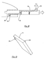
- Figure 1 is an exploded perspective view of a display embodying the present invention,
- Figure 2a is a side view of the display of Figure 1 in a folded position,
- Figure 2b is a side view of the display of Figure 1 in a partly unfolded configuration
- Figure 2c is a side view of the display screen of Figure 1 in an unfolded, operative position,
- Figure 3 is a perspective view from one side and to the rear of part of the display of Figure 1,
- Figure 4a is a plan view, partly broken away, of part of Figure 3 provided with a module,
- Figure 4b is a broken away side view of the module of Figure 4a,
- Figure 5a is a diagrammatic illustration of a latch and connector of the module and connector of Figure 1,
- Figure 5b is a perspective view of the module of Figure 5a,
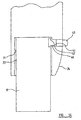
- Figure 5c is a diagrammatic illustration of a further latch,
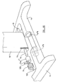
- Figure 6a is an exploded perspective view on a larger scale of part of the support of Figure 1,
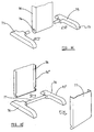
- Figure 6b is a perspective view of on a larger scale of part of an alternative support,
- Figure 6c is a perspective view of a further support,
- Figure 6d is a perspective view of a still further support, and
- Figure 7 is a perspective view from the front and to one side of a further display embodying the present invention.
-
- Referring now to Figure 1, a
computer system 10 is shown embodying the present invention. The computer system comprises adisplay 11, and shown in dashed outline a processor unit 12 which is provided with, for example, a motherboard having a CPU, memory, and a data storage drive such as a hard disk drive. Thedisplay 11 comprises adisplay screen 13 and asupport 14. Thesupport 14 comprises abase part 15 and an upwardly extendingcolumn 16. Thecolumn 16 comprisesopposed side parts connectors 18 are provided.Modules connectors 18 by holding the modules in a generally vertical orientation as seen in Figure 1 and by engaging the modules andconnectors 18 in a generally horizontal direction as shown by arrows A and B. - As shown in Figures 3 and 4, the
column 16 is provided with an inwardly directedhand hold 39 to enable thedisplay 11 to be picked up. - As shown in Figure 1, the
base part 15 comprises a pair of rearwardly extendingarms 14a, 14b, connected by a front part 14c in which arecess 45 is provided. Thearms 14a, 14b and forward part 14c define a recess 14d in which abase module 56 may be located. This may be simply a box in which power supply units for thedisplay 11 and the various modules may be neatly gathered. More preferably, thebase module 56 comprises a power supply unit operable to receive an alternating current power input shown at 56a and having a DC power output connector 56b which is engagable with a DC power input connector 56c on thesupport 14 to supply DC power to thedisplay screen 13 and to any modules connected to thecolumn 16. For additional stability, a pair of forwardly extendingarms - It will be apparent that a power supply unit may alternatively be provided in the
support 14, in thebase 15 orcolumn 16 as appropriate. - In the present example the
modules module 19 comprises an optical disk drive such as a DVD or CD-ROM and themodule 20 comprises a wireless communication module such as a Bluetooth module. It will however be apparent that any module with any appropriate functionality may be provided as desired. The connection to the processor unit 12 may be a simple cable leading from eachconnector 18 to an appropriate connector on the processor unit 12, or alternatively some of appropriate general connection, such as a USB connection may be provided by the processor unit 12 and thedisplay 11. It might even be envisaged that one of the modules, or even the support itself, be provided with a USB hub to facilitate communication between thescreen 13, modules and the processor units 12. It will be apparent that the processor unit 12 may as appropriate be integrated with thesupport 14, into thebase 15 and/orcolumn 16 as appropriate. Thecolumn 16 may preferably act as a hub for any other connection as desired, for example a telephone connection, a supply of direct or alternating current, a USB connection and any other signal as desired so that the number of cables extending from thedisplay 11 across a desk top is limited. - As seen in more detail in Figure 3, the
column 16 comprises aforward face 23 which is seen by the viewer when thedisplay 11 is in use. Thecolumn 16 is further provided with aback part 24 which in the present example is removably detachable from thecolumn 16 as desired. A pair of flanges 25, 26 of thefront face 23 and theback plate 24 definerecesses column 16. The ends of the recesses are provided by side faces 29, 30 of the column and a plurality ofconnectors 18 are each provided on thefaces part 33 of amodule module 19 into position and to restrain movement of the module. - Suitable latches are provided to hold the
module face module hook 35 pivotally attached at 36 to themodule aperture 37 of theside face 29 and engages a lip of theaperture 37. This thus acts to resist rotational force due to gravity which would cause module to rotate in a clockwise direction as seen in Figure 5a causing theconnectors 34 of themodule 19 to rotate out of thesockets 18 and disengage the module from thecolumn 16. To release thehook 35, abutton 38 is provided on themodule 19 connected to thehook 35 to release it from theaperture 37. - In addition, or alternatively, the
module displaceable hook 40 on a rearward face thereof to engage anaperture 41 provided in theremovable back plate 24 as shown in Figure 5b to engage aface 42 of theaperture 41. In the example of Figure 5b, theback plate 24 is further provided with abutton 43 which may be depressed to urge thehook 40 to the left as shown in Figure 5b such that thehook 40 is released from theaperture 41 and themodule 19 may be released from theconnector 18. - It will be apparent that any other latch or positive engagement means may be provided as desired.
- To enable the
support 14 to be moved to a collapsed or folded position for ease of transportation, thecolumn 16 is preferably pivotally connected to thebase part 15. In the example of Figure 6a, the lower part of thecolumn 16 is provided at side faces thereof with a pair of co-axial outwardly extending cylindrical projections 44a, 44b. Thebase part 15 is provided with arecess 45 at a middle part thereof. Therecess 45 has opposed inwardly directed faces 46a, 46b. In each face 46a, 46b is a generally cylindrical opening 47a, 47b in which the respective cylindrical projection 44a, 44b is received, providing a pivotal connection between thebase part 15 and thecolumn 16. In the example of Figure 6a, to provide for thecolumn 16 to be pivotal movable between a selected one of a plurality of preferred positions, each cylindrical projection 44a, 44b has a plurality of circumferentially spaced indentations. Each aperture 47a, 47b similarly has a number of inwardly directed ridges 49 which are shaped to engage theindentations 48. When thecolumn 16 is rotated relative to thebase 14, the user will feel a resistance as the column is rotated such that theindentations 48 are moved out of engagement with the one or more ridges 49, and then a positive engagement and potentially an audible click as theindentations 48 reengage with the ridges 49 in a next position. - Of course, it will be apparent that any appropriate pivotal connection between the
column 16 andbase part 15 may be provided as desired. For example, in the alternative of Figure 6b the cylindrical openings 47'a, 47'b are not provided with inwardly directed ridges. Instead, in this embodiment thecolumn 16 is provided with outwardly directedmetal posts 70 on which are received acylinder 71 made of a plastics material. Ahelical spring 72 is disposed around thecylinder 71. A first end part 72a of the spring engages aslot 73 provided in the side wall of thecolumn 15. The assembly of thecylinder 71 andspring 76 is received in a cylindrical recess 47'a, wherein theother end 72b of thespring 72 will engage thebase part 15. When the display is assembled, i.e. where aplastics cylinder 71 andspring 72 has been mounted on eachmetal peg 70, and the respective cylinder and spring being received in the respective cylindrical opening 47'a, 47'b, it will be apparent that thecolumn 16 will be pivotally movable relative to thebase part 70 against the frictional resistance between themetal peg 70 and the aperture of thecylindrical part 71, whilst thespring 72 resists movement of thecolumn 16 andbase part 15 towards a folded, stored position, and assists in overcoming the frictional engagement between themetal peg 70 and theplastics cylinder 71. Theplastics cylinder 71 has an aperture 71a in which themetal peg 70 is received themetal peg 70 is slightly too large for the aperture 71a, such that there is a frictional resistance to relative movement between thecylinder 71 and thepeg 70. By virtue of frictional engagement between thespring 72, the generally cylindrical opening 71a and thecylinder 71, there is also frictional resistance to relative movement between thecylinder 71 and thespring 72. - It will be apparent that any other assembly or a
base part 15 andcolumn 16 may be provided as desired. For example, as shown in Figure 6c a column 16' is shown provided with acylindrical apertures 74 at an end part thereof which engage a pair offeet 75 which together form a base part 15'. In Figure 6d, abase part 15" comprises a pair of feet connected by a generally cylindrical connectingpart 77, and acolumn 16" is formed by connecting twocolumn parts 78 such that they enclose the connectingpart 77 and permit relative rotational movement betweenbase part 15" andcolumn 16". - As shown in Figures 1 and 3, an
upper surface 50 of thecolumn 16 is provided with a screen engagement part to engage a display screen, in the present example a recess 50a. In the present example as shown in Figure 1, thedisplay screen 13 is provided with a screen support part having anarm 51 which is pivotally connected by apivotal connection 52 to thedisplay screen 13. At the opposite end of thearm 51, apivotal connection 53 is provided connected to a lug 54 to engage the recess 50a. A recessedslot 51a is provided in thecolumn 16 to at least partially receive thearm 51 to allow thedisplay 11 to be folded as shown in Figure 2a. In this example, thescreen 13 is also provided with a portrait-landscape mechanism 55 whereby the screen may be rotated between portrait and landscape positions. The position of thepivotal connections column 16 andbase 14 allows the user to vary the height and position of thedisplay screen 13 with a great deal of flexibility, while the engagement of the lug 54 and recess 50a permits the screen to rotate about an axis extending generally co-linear with thecolumn 16. - As shown in Figures 2a to 2c, the
display 11 may be moved from a folded configuration as shown in Figure 2a where thearm 51 lies adjacent thedisplay screen 13 and thecolumn 16, and thebase part 15 is folded to a position where it is relatively close to thecolumn 16 to provide a relatively compact and more easily portable configuration. By pivoting the various components about the pivotal connections as shown in Figure 2b, thedisplay 11 can be unfolded to an erect, operational position as shown in Figure 2c. It will be apparent that in the present example, it will be necessary to remove anymodules base part 15 andcolumn 16 to be pivoted such that they are relatively close to one another, unless thebase part 15 is shaped such that the pivotal connection between thebase part 15 and thecolumn 16 is spaced away from thearms 14a, 14b such that thedisplay screen 13 and thearms 14a, 14b. - To provide for additional height adjustment of the
display screen 13, it might be envisaged that thecolumn 16 may be telescopically extendible, or the connection between thearm 51 and thecolumn 16 may itself be telescopic, for example by an appropriate extending configuration of the lug 54 or indeed by any other means as desired. - In an alternative embodiment as shown in Figure 7 a support 12' is shown having a base part 15' and a column 16'. The column 16' is provided with a screen support part comprising sliding
connection 60 whereby the vertical height of adisplay screen 61 may be adjusted as shown by arrows C, in this example by providing connectors on the screen 61 (not shown) received in a vertically extendingslot 62 provided on the column 16'. The column 16' and base part 15' are relatively pivotally movable in the manner to the embodiment of Figures 1 to 6 to permit the support 12' to be collapsed for carrying purposes. - In the present specification "comprises" means "includes or consists of" and "comprising" means "including or consisting of".
- The features disclosed in the foregoing description, or the following claims, or the accompanying drawings, expressed in their specific forms or in terms of a means for performing the disclosed function, or a method or process for attaining the disclosed result, as appropriate, may, separately, or in any combination of such features, be utilised for realising the invention in diverse forms thereof.
Claims (15)
- A display for a computer system comprising a display screen and a support for supporting the display screen,
the support comprising a base and a column attached to the base,
the column being provided with a screen support part and with at least one connector to which a module of the computer system may be connected. - A display according to claim 1 wherein the connector is located such that when a module is connected thereto, the module is located at least partly behind the display screen.
- A display according to claims 1 or claim 2 wherein the column comprises opposed side faces and wherein a plurality of connectors are located on each opposed side face.
- A display according to any one of the preceding claims wherein the connectors are connected to an output connection for communication with a processor unit of the computer system.
- A display according to any one of claims 1 to 4 wherein a processor unit is provided in the support.
- A display according to any one of the preceding claims wherein a power supply unit is provided in the support.
- A display according to any one of claims 1 to 5 wherein a power supply unit is located in a base module adjacent the column and behind the base.
- A display according to any one of the preceding claims wherein the base comprises a pair of rearwardly extending arms interconnected by a forward part, and wherein the column is connected to the forward part.
- A display according to claim 8 where dependant upon claim 7 wherein the power supply module is adapted to be received in between the rearwardly extending arms.
- A display according to claim 9 wherein the power supply module is adapted to supply power to the display screen and any modules connected to the support.
- A display according to any one of the preceding claims wherein the column is foldably connected to the base.
- A display according to claim 11 wherein the screen support part comprises a first rotating part located adjacent the column and a second pivotal connection in the vicinity of the screen whereby the support and display screen support part may be folded into a collapsed configuration.
- A display according to any one of the preceding claims 1 to 11 wherein the column is provided with a screen support part comprising a sliding connection whereby the display screen is vertically slideable relative to the column.
- A display according to any one of the preceding claims further comprising at least one module engaged with a connector on the support.
- A computer system comprising a display according to any one of claims 1 to 14.
Priority Applications (2)
| Application Number | Priority Date | Filing Date | Title |
|---|---|---|---|
| EP02354174A EP1420327A1 (en) | 2002-11-14 | 2002-11-14 | Support |
| US10/706,046 US7145767B2 (en) | 2002-11-14 | 2003-11-13 | Support |
Applications Claiming Priority (1)
| Application Number | Priority Date | Filing Date | Title |
|---|---|---|---|
| EP02354174A EP1420327A1 (en) | 2002-11-14 | 2002-11-14 | Support |
Publications (1)
| Publication Number | Publication Date |
|---|---|
| EP1420327A1 true EP1420327A1 (en) | 2004-05-19 |
Family
ID=32116340
Family Applications (1)
| Application Number | Title | Priority Date | Filing Date |
|---|---|---|---|
| EP02354174A Withdrawn EP1420327A1 (en) | 2002-11-14 | 2002-11-14 | Support |
Country Status (2)
| Country | Link |
|---|---|
| US (1) | US7145767B2 (en) |
| EP (1) | EP1420327A1 (en) |
Cited By (5)
| Publication number | Priority date | Publication date | Assignee | Title |
|---|---|---|---|---|
| EP1772662A3 (en) * | 2005-10-06 | 2007-10-24 | LG Electronics Inc. | Stand for image display device |
| US7703736B2 (en) | 2005-10-06 | 2010-04-27 | Lg Electronics Inc. | Stand for image display device |
| EP2503211A3 (en) * | 2011-03-21 | 2012-10-10 | BOE Technology Group Co., Ltd. | Flat display device |
| EP2806630A1 (en) * | 2013-05-24 | 2014-11-26 | Funai Electric Co., Ltd. | Display device |
| EP3674592A1 (en) * | 2018-12-31 | 2020-07-01 | Samsung Electronics Co., Ltd. | Display apparatus |
Families Citing this family (56)
| Publication number | Priority date | Publication date | Assignee | Title |
|---|---|---|---|---|
| AUPS285202A0 (en) * | 2002-06-07 | 2002-06-27 | Claiteal Pty Ltd | Stand for flat panel display |
| US7652876B2 (en) * | 2002-06-13 | 2010-01-26 | Gerald Moscovitch | Graphics and monitor controller assemblies in multi-screen display systems |
| IL159838A0 (en) | 2004-01-13 | 2004-06-20 | Yehuda Binder | Information device |
| JP2005267773A (en) * | 2004-03-19 | 2005-09-29 | Orion Denki Kk | Liquid crystal display device embedded with disk device |
| USD504426S1 (en) * | 2004-06-08 | 2005-04-26 | Flextronics International Usa, Inc. | Desktop computer |
| CA2634827C (en) | 2005-11-07 | 2013-04-23 | Jerry Moscovitch | Controller and graphics assemblies in multi-screen display systems |
| US20070124524A1 (en) * | 2005-11-30 | 2007-05-31 | Pressure Drop Inc. | Paper tray with integrated computing accessory devices |
| US7338330B2 (en) * | 2005-12-23 | 2008-03-04 | Aamp Of Florida, Inc. | Vehicle power system with integrated graphics display |
| US20070152113A1 (en) * | 2005-12-30 | 2007-07-05 | Okuley James M | Compressed workspace notebook computer |
| US7733633B2 (en) * | 2006-03-01 | 2010-06-08 | Pdi Communication Systems, Inc. | Video display unit support bracket |
| TWI295705B (en) * | 2006-07-26 | 2008-04-11 | Compal Electronics Inc | Portable electronic apparatus with function of adjusting tilt angle of body and apparatus base thereof |
| JP4777846B2 (en) * | 2006-08-23 | 2011-09-21 | 富士通株式会社 | Information processing device |
| US7587726B2 (en) * | 2006-10-26 | 2009-09-08 | Alco Electronics Limited | Display with disc player |
| US7719832B2 (en) * | 2006-10-31 | 2010-05-18 | Hewlett-Packard Development Company, L.P. | Computing device mounting system |
| TWI344303B (en) * | 2007-04-13 | 2011-06-21 | Qisda Corp | Holding apparatus |
| US7751183B2 (en) * | 2007-12-14 | 2010-07-06 | Harris Technology, Llc | USB stacking devices and applications |
| US20090223908A1 (en) * | 2008-03-07 | 2009-09-10 | Wal-Mart Stores, Inc. | Device Display Unit |
| US20090223907A1 (en) * | 2008-03-07 | 2009-09-10 | Wal-Mart Stores, Inc. | Merchandise Display Unit |
| US7845605B2 (en) * | 2008-03-17 | 2010-12-07 | Bose Corporation | Multimedia device bracket |
| US8364866B2 (en) * | 2008-04-14 | 2013-01-29 | Bose Corporation | Automatic device function control based on device hub coupling selection |
| US7813118B2 (en) * | 2008-04-14 | 2010-10-12 | Bose Corporation | Device bracket with integrated device hub |
| US7830650B2 (en) * | 2008-07-24 | 2010-11-09 | Dell Products L.P. | Externally connectable thin display |
| US20100177473A1 (en) * | 2008-07-31 | 2010-07-15 | Advanpos Technology Co. Ltd. | Computer device |
| US7793026B1 (en) * | 2008-10-13 | 2010-09-07 | Hewlett-Packard Development Company, L.P. | Computer system with peripheral modules attached to a display/CPU assembly |
| US20100332711A1 (en) * | 2009-06-30 | 2010-12-30 | Kin Ip Ll | Display device with built in hard drive docking station |
| TWM384508U (en) * | 2010-01-15 | 2010-07-11 | Aopen Inc | Vapor chamber device with metal mesh heat-dissipating structure |
| CN102193584B (en) * | 2010-03-05 | 2014-12-03 | 鸿富锦精密工业(深圳)有限公司 | Integrated computer |
| US9074721B2 (en) | 2010-06-09 | 2015-07-07 | Alex Lau | Support system |
| US9316346B2 (en) | 2010-06-09 | 2016-04-19 | Colebrook Bosson Saunders (Products) Limited | Support system |
| USD684982S1 (en) | 2010-08-11 | 2013-06-25 | Colebrook Bosson Saunders (Products) Limited | Display support with indicator window |
| WO2013015771A1 (en) | 2011-07-22 | 2013-01-31 | Hewlett-Packard Development Company, L.P. | Display device stand |
| EP2766784B1 (en) | 2011-10-14 | 2020-12-23 | Ergotron, Inc. | Tablet and monitor support systems |
| US20130318274A1 (en) * | 2012-05-24 | 2013-11-28 | Radu Oprea | Scalable Portable-Computer System |
| US20140093303A1 (en) * | 2012-09-28 | 2014-04-03 | Apple Inc. | Removable stand for computing device |
| JP2014232849A (en) * | 2013-05-30 | 2014-12-11 | 株式会社東芝 | Stand for electronic apparatus, and electronic apparatus |
| US10698450B2 (en) * | 2013-09-27 | 2020-06-30 | Hewlett-Packard Development Company, L.P. | Detachable display member with support member |
| US20150227177A1 (en) * | 2014-02-12 | 2015-08-13 | AMES ADT, Inc. | Tablet computer and method for coupling a computer cable to the tablet computer |
| CN105094212B (en) * | 2014-04-28 | 2019-04-12 | 富泰华工业(深圳)有限公司 | The display of bracket and the application bracket |
| TWI578881B (en) * | 2014-11-25 | 2017-04-11 | 樺漢科技股份有限公司 | Point of sale device |
| CN204254178U (en) * | 2014-11-28 | 2015-04-08 | 高创(苏州)电子有限公司 | A kind of display unit supporting base and display unit |
| US9727096B1 (en) * | 2016-02-09 | 2017-08-08 | Lenovo (Singapore) Pte. Ltd. | All-in-one with sliding mechanism to reveal removable modules |
| US20170255291A1 (en) * | 2016-03-02 | 2017-09-07 | Matthew Calvin Hinson | Portable Interactive Projection Display Apparatus |
| TWM525473U (en) * | 2016-03-08 | 2016-07-11 | 揚昇照明股份有限公司 | Computer apparatus |
| US10485312B2 (en) * | 2016-08-30 | 2019-11-26 | Otter Products, Llc | Protective case system with stand |
| US9888594B1 (en) * | 2016-09-30 | 2018-02-06 | Hewlett Packard Enterprise Development Lp | Devices including a cavity region to house ports |
| US10429883B2 (en) * | 2017-01-25 | 2019-10-01 | Hewlett-Packard Development Company, L.P. | Curved modular display |
| US10623043B2 (en) | 2018-01-23 | 2020-04-14 | Otter Products, Llc | Protective case for electronic device |
| US10750844B2 (en) | 2018-03-15 | 2020-08-25 | Otter Products, Llc | Protective case for use with device grip |
| US10694835B2 (en) | 2018-03-15 | 2020-06-30 | Otter Products, Llc | Protective case for use with device grip |
| US10452096B1 (en) * | 2018-06-15 | 2019-10-22 | Dell Products L.P. | Configurable all-in-one modular desktop computing system |
| US11068030B2 (en) | 2018-12-19 | 2021-07-20 | Otter Products, Llc | Stand for use with electronic device |
| USD897329S1 (en) | 2019-07-02 | 2020-09-29 | Otter Products, Llc | Case for a smartphone |
| US10955873B1 (en) * | 2019-11-06 | 2021-03-23 | Lenovo (Singapore) Pte. Ltd. | Display device |
| US11745670B2 (en) | 2020-05-06 | 2023-09-05 | Otter Products, Llc | Protective case system for use with electronic device |
| US11633025B2 (en) | 2020-06-26 | 2023-04-25 | Otter Products, Llc | Carrying case with stand |
| CN112901929A (en) * | 2021-01-17 | 2021-06-04 | 广东培正学院 | Big data cloud calculates all-in-one |
Citations (6)
| Publication number | Priority date | Publication date | Assignee | Title |
|---|---|---|---|---|
| US6024335A (en) * | 1996-11-06 | 2000-02-15 | Samsung Electronics Co., Ltd. | Flat-panel display apparatus |
| US6229584B1 (en) * | 1999-11-15 | 2001-05-08 | Compal Electronics, Inc. | Liquid crystal display monitor having a monitor stand with a replaceable housing part |
| US6343006B1 (en) * | 1998-11-20 | 2002-01-29 | Jerry Moscovitch | Computer display screen system and adjustable screen mount, and swinging screens therefor |
| US6366453B1 (en) * | 2000-04-14 | 2002-04-02 | Acer Incorporated | Planar display unit that is separably connected to a computer |
| US6366452B1 (en) * | 2000-02-24 | 2002-04-02 | Acer Incorporated | Flat display with a replaceable base stand |
| US6392873B1 (en) * | 1999-06-16 | 2002-05-21 | Kabushiki Kaisha Toshiba | Data-processing apparatus having a stand supporting a liquid-crystal display unit |
Family Cites Families (3)
| Publication number | Priority date | Publication date | Assignee | Title |
|---|---|---|---|---|
| US5987211A (en) * | 1993-01-11 | 1999-11-16 | Abecassis; Max | Seamless transmission of non-sequential video segments |
| KR100212314B1 (en) * | 1996-11-06 | 1999-08-02 | 윤종용 | Stand device of lcd display apparatus |
| US7061754B2 (en) * | 2002-06-13 | 2006-06-13 | Gerald Moscovitch | LCD system having integrated CPU |
-
2002
- 2002-11-14 EP EP02354174A patent/EP1420327A1/en not_active Withdrawn
-
2003
- 2003-11-13 US US10/706,046 patent/US7145767B2/en active Active
Patent Citations (6)
| Publication number | Priority date | Publication date | Assignee | Title |
|---|---|---|---|---|
| US6024335A (en) * | 1996-11-06 | 2000-02-15 | Samsung Electronics Co., Ltd. | Flat-panel display apparatus |
| US6343006B1 (en) * | 1998-11-20 | 2002-01-29 | Jerry Moscovitch | Computer display screen system and adjustable screen mount, and swinging screens therefor |
| US6392873B1 (en) * | 1999-06-16 | 2002-05-21 | Kabushiki Kaisha Toshiba | Data-processing apparatus having a stand supporting a liquid-crystal display unit |
| US6229584B1 (en) * | 1999-11-15 | 2001-05-08 | Compal Electronics, Inc. | Liquid crystal display monitor having a monitor stand with a replaceable housing part |
| US6366452B1 (en) * | 2000-02-24 | 2002-04-02 | Acer Incorporated | Flat display with a replaceable base stand |
| US6366453B1 (en) * | 2000-04-14 | 2002-04-02 | Acer Incorporated | Planar display unit that is separably connected to a computer |
Cited By (10)
| Publication number | Priority date | Publication date | Assignee | Title |
|---|---|---|---|---|
| EP1772662A3 (en) * | 2005-10-06 | 2007-10-24 | LG Electronics Inc. | Stand for image display device |
| US7703736B2 (en) | 2005-10-06 | 2010-04-27 | Lg Electronics Inc. | Stand for image display device |
| CN1945748B (en) * | 2005-10-06 | 2010-05-12 | Lg电子株式会社 | Stand for image display device |
| CN1945749B (en) * | 2005-10-06 | 2010-10-20 | Lg电子株式会社 | Stand for image display device |
| EP2503211A3 (en) * | 2011-03-21 | 2012-10-10 | BOE Technology Group Co., Ltd. | Flat display device |
| EP2806630A1 (en) * | 2013-05-24 | 2014-11-26 | Funai Electric Co., Ltd. | Display device |
| US9491893B2 (en) | 2013-05-24 | 2016-11-08 | Funai Electric Co., Ltd. | Display device |
| USRE47914E1 (en) | 2013-05-24 | 2020-03-17 | Funai Electric Co., Ltd. | Display device |
| EP3674592A1 (en) * | 2018-12-31 | 2020-07-01 | Samsung Electronics Co., Ltd. | Display apparatus |
| US11262019B2 (en) | 2018-12-31 | 2022-03-01 | Samsung Electronics Co., Ltd. | Display apparatus |
Also Published As
| Publication number | Publication date |
|---|---|
| US7145767B2 (en) | 2006-12-05 |
| US20040150945A1 (en) | 2004-08-05 |
Similar Documents
| Publication | Publication Date | Title |
|---|---|---|
| US7145767B2 (en) | Support | |
| US6480376B1 (en) | Elevationally adjustable portable computer docking station | |
| US5568359A (en) | Portable computer desktop docking system | |
| US7298610B2 (en) | Supporting apparatus for portable computer | |
| US6246575B1 (en) | Modular computer | |
| JP3432798B2 (en) | Integrated docking tray assembly | |
| TW588233B (en) | Pedestal computer docking station | |
| KR102223569B1 (en) | Stabilising device | |
| US7200702B2 (en) | Mobile device expansion system | |
| US7641348B2 (en) | Integrated portable computer projector system | |
| US7129931B2 (en) | Multipurpose computer display system | |
| AU2008101165B4 (en) | Docking station for hand held electronic devices | |
| JP4531263B2 (en) | Computer display screen system, adjustable display screen mount and swivel display screen for display screen system | |
| US5899421A (en) | Stand for a portable computer | |
| US5825614A (en) | Compact personal computer with LCD monitor | |
| US20100053876A1 (en) | Laptop computer | |
| WO1999063422A1 (en) | Desktop portable computer vertical dock system | |
| CN102473022A (en) | Modular flat-panel monitor stand | |
| JP2001069390A (en) | Image pickup device which can be attached to electronic appliance | |
| US6940714B2 (en) | Support for a display screen | |
| EP1304610A1 (en) | Stabilizing system for computer hardware | |
| KR100654797B1 (en) | Computer apparatus | |
| EP1302838A1 (en) | Stabilizing system for computer hardware | |
| JP2004252942A (en) | Personal computer which can be disassembled | |
| CN215721807U (en) | Electronic product support |
Legal Events
| Date | Code | Title | Description |
|---|---|---|---|
| PUAI | Public reference made under article 153(3) epc to a published international application that has entered the european phase |
Free format text: ORIGINAL CODE: 0009012 |
|
| AK | Designated contracting states |
Kind code of ref document: A1 Designated state(s): AT BE BG CH CY CZ DE DK EE ES FI FR GB GR IE IT LI LU MC NL PT SE SK TR |
|
| AX | Request for extension of the european patent |
Extension state: AL LT LV MK RO SI |
|
| AKX | Designation fees paid | ||
| REG | Reference to a national code |
Ref country code: DE Ref legal event code: 8566 |
|
| STAA | Information on the status of an ep patent application or granted ep patent |
Free format text: STATUS: THE APPLICATION IS DEEMED TO BE WITHDRAWN |
|
| 18D | Application deemed to be withdrawn |
Effective date: 20041120 |