EP1420163A2 - Control valve for variable capacity compressor - Google Patents
Control valve for variable capacity compressor Download PDFInfo
- Publication number
- EP1420163A2 EP1420163A2 EP03026082A EP03026082A EP1420163A2 EP 1420163 A2 EP1420163 A2 EP 1420163A2 EP 03026082 A EP03026082 A EP 03026082A EP 03026082 A EP03026082 A EP 03026082A EP 1420163 A2 EP1420163 A2 EP 1420163A2
- Authority
- EP
- European Patent Office
- Prior art keywords
- bellows
- valve
- patch member
- main body
- end portion
- Prior art date
- Legal status (The legal status is an assumption and is not a legal conclusion. Google has not performed a legal analysis and makes no representation as to the accuracy of the status listed.)
- Granted
Links
Images


Classifications
-
- F—MECHANICAL ENGINEERING; LIGHTING; HEATING; WEAPONS; BLASTING
- F04—POSITIVE - DISPLACEMENT MACHINES FOR LIQUIDS; PUMPS FOR LIQUIDS OR ELASTIC FLUIDS
- F04B—POSITIVE-DISPLACEMENT MACHINES FOR LIQUIDS; PUMPS
- F04B27/00—Multi-cylinder pumps specially adapted for elastic fluids and characterised by number or arrangement of cylinders
- F04B27/08—Multi-cylinder pumps specially adapted for elastic fluids and characterised by number or arrangement of cylinders having cylinders coaxial with, or parallel or inclined to, main shaft axis
- F04B27/14—Control
- F04B27/16—Control of pumps with stationary cylinders
- F04B27/18—Control of pumps with stationary cylinders by varying the relative positions of a swash plate and a cylinder block
- F04B27/1804—Controlled by crankcase pressure
-
- F—MECHANICAL ENGINEERING; LIGHTING; HEATING; WEAPONS; BLASTING
- F04—POSITIVE - DISPLACEMENT MACHINES FOR LIQUIDS; PUMPS FOR LIQUIDS OR ELASTIC FLUIDS
- F04B—POSITIVE-DISPLACEMENT MACHINES FOR LIQUIDS; PUMPS
- F04B27/00—Multi-cylinder pumps specially adapted for elastic fluids and characterised by number or arrangement of cylinders
- F04B27/08—Multi-cylinder pumps specially adapted for elastic fluids and characterised by number or arrangement of cylinders having cylinders coaxial with, or parallel or inclined to, main shaft axis
- F04B27/14—Control
- F04B27/16—Control of pumps with stationary cylinders
- F04B27/18—Control of pumps with stationary cylinders by varying the relative positions of a swash plate and a cylinder block
- F04B27/1804—Controlled by crankcase pressure
- F04B2027/1809—Controlled pressure
- F04B2027/1813—Crankcase pressure
-
- F—MECHANICAL ENGINEERING; LIGHTING; HEATING; WEAPONS; BLASTING
- F04—POSITIVE - DISPLACEMENT MACHINES FOR LIQUIDS; PUMPS FOR LIQUIDS OR ELASTIC FLUIDS
- F04B—POSITIVE-DISPLACEMENT MACHINES FOR LIQUIDS; PUMPS
- F04B27/00—Multi-cylinder pumps specially adapted for elastic fluids and characterised by number or arrangement of cylinders
- F04B27/08—Multi-cylinder pumps specially adapted for elastic fluids and characterised by number or arrangement of cylinders having cylinders coaxial with, or parallel or inclined to, main shaft axis
- F04B27/14—Control
- F04B27/16—Control of pumps with stationary cylinders
- F04B27/18—Control of pumps with stationary cylinders by varying the relative positions of a swash plate and a cylinder block
- F04B27/1804—Controlled by crankcase pressure
- F04B2027/1822—Valve-controlled fluid connection
- F04B2027/1827—Valve-controlled fluid connection between crankcase and discharge chamber
-
- F—MECHANICAL ENGINEERING; LIGHTING; HEATING; WEAPONS; BLASTING
- F04—POSITIVE - DISPLACEMENT MACHINES FOR LIQUIDS; PUMPS FOR LIQUIDS OR ELASTIC FLUIDS
- F04B—POSITIVE-DISPLACEMENT MACHINES FOR LIQUIDS; PUMPS
- F04B27/00—Multi-cylinder pumps specially adapted for elastic fluids and characterised by number or arrangement of cylinders
- F04B27/08—Multi-cylinder pumps specially adapted for elastic fluids and characterised by number or arrangement of cylinders having cylinders coaxial with, or parallel or inclined to, main shaft axis
- F04B27/14—Control
- F04B27/16—Control of pumps with stationary cylinders
- F04B27/18—Control of pumps with stationary cylinders by varying the relative positions of a swash plate and a cylinder block
- F04B27/1804—Controlled by crankcase pressure
- F04B2027/184—Valve controlling parameter
- F04B2027/1859—Suction pressure
Definitions
- the present invention relates to a control valve for a variable capacity compressor.
- the bellows pressure response valve has an advantage in that it is small and that a long pressure responding stroke can be obtained as compared with a diaphragm pressure response valve.
- a bellows pressure response valve having a bellows as a pressure sensing element and with an airtight structure and transferring expansion and contraction of the bellows to a ball valve through a valve rod supported to be movable in a valve lifting direction from a valve housing to thereby change a valve opening degree, in which a spherical joint structure formed of an end plate integral with the bellows and a ball is incorporated into a connection portion between the bellows and the valve rod as disclosed in Japanese Patent Application Laid-open No. 2000-88132.
- the invention relates to a control valve for a variable capacity compressor, which comprises abellows main body retained as a pressure sensing element in a bellows case with an airtight structure and transfers expansion and contraction of the bellows main body in response to a variation in inlet pressure of the variable capacity compressor to a valve element through a valve rod supported to be movable in a valve lifting direction from a valve housing integral with the bellows case to thereby change a valve opening degree.
- a patch member is provided to a movable-side end portion of the bellows main body and is formed with a fitting recessed portion, a valve rod being fitted to be able to float in the fitting recessed portion, and a compression coil spring is disposed between the patch member and a lower patch member for supporting a fixed-side end portion of the bellows main body.
- control valve according to the invention may take the following forms.
- a contact end portion of the valve rod in contact with the fitting recessed portion is in a substantially central position in a bellows expanding/contracting direction of the bellows main body or on the fixed-side end portion side of the central position.
- An inner face of the fixed-side end portion of the bellows main body is supported on the lower patch member, an outer face of the fixed-side end portion is supported on an adjusting screw member provided to the bellows case, and a side face of the fixed-side end portion of the bellows main body is supported on an inner face of the bellows case.
- a bottom portion of the fitting recessed portion forms a stopper face portion which can come in contact with a stopper face portion formed at a central portion of the lower patch member.
- the fixed-side end portion of the bellows main body is mounted to the lower patch member substantially in the same shape as the patch member, a side face of the lower patch member is supported on a support tube portion formed to stand from the bellows case, and a stopper face portion formed at a central portion of the lower patch member is supported on a support portion extending from an adjusting screw member.
- a ball is mounted in the fitting recessed portion and the valve rod is fitted to be able to float in the fitting recessed portion with a lower end of the valve rod in contact with the ball.
- control valve for the variable capacity compressor With the control valve for the variable capacity compressor according to the invention, it is possible to minimize hysteresis in valve opening/closing operation and to enhance accuracy in the valve opening/closing operation even if straightness of the bellows is somewhat poor.
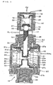
- the control valve 10 shown in FIG. 1 is inserted and fixed into a control valve mounting hole formed in a housing of a variable capacity compressor (not shown) as a flow control valve for a flow rate of a refrigerant from a discharge pipe for the refrigerant to a crankcase.
- the control valve 10 is formed of a tubular valve housing 11, an end cap 12 mounted to an upper end of the valve housing 11, and a bellows case 13 connected to a lower end of the valve housing 11 by caulking.
- An assembly of the valve housing 11 and the end cap 12 is formed of a valve chest 14, a valve port 16 defined by a valve seat portion 15, a first port 17 formed on one side of the valve port 16, a spring receiving seat 23 disposed on the other side of the valve port 16 through the valve chest 14, a second port 18 formed in the spring receiving seat 23, and avalve rod retaining hole 19.
- the end cap 12 is mounted with a filter 20 for the second port 18 by integral molding.
- a ball valve 21 is provided in the valve chest 14. By movements of the ball valve 21 in a vertical direction (valve lifting direction), a clearance between the ball valve 21 and the valve seat portion 15 changes to determine a valve opening degree. Between a ball receiving member 22 and the spring receiving seat 23 in the valve chest 14, a compression coil spring 24 for constantly biasing the ball valve 21 in a valve closing direction is provided.
- valve rod retaining hole 19 is formed concentrically with the valve seat portion 15. Through the valve rod retaining hole 19, a round valve rod 25 is inserted to be movable in an axial direction (valve lifting direction) of the valve rod retaining hole 19.
- a lower end portion of the valve rod 25 is fitted in a fitting recessed portion 31b of a patch member 31 which will be described later.
- the lower end portion of the valve rod 25 is rounded or formed into a hemispherical shape to form a contact end portion 25a.
- a bellows 26 having an airtight structure is disposed.
- An inside of a bellows main body 27 is under vacuum.
- the patch member 31 and a lower patch member 28 are disposed to face each other.
- the patch member 31 is provided to a movable-side end portion (upper end portion) of the bellows main body 27 and the lower patch member 28 is provided to a fixed-side end portion (lower end portion) of the bellows main body 27.
- the lower patch member 28 is disposed inside a bellows main body bottom portion 27b formed of a thick-walled portion at a lower portion of the bellows main body 27 and supports the fixed-side end portion of the bellows main body 27.
- a compression coil spring 30 for biasing the bellows 26 in an expanding direction is disposed in a compressed state between the lower patch member 28 and the patch member 31.
- the patch member 31 is formed of a base portion 31c in a form of a circular flat plate, the fitting recessed portion 31b formed by sinking a central portion of the base portion 31c deep downward (toward the lower patch member 28), and a large-diameter portion 31d located midway between the base portion 31c and the fitting recessed portion 31b and forming a shallow recessed portion.
- the fitting recessed portion 31b of the patch member 31 has such an inside diameter as to allow the patch member 31 to incline with respect to the valve rod 25.
- a bottom portion of the fitting recessed portion 31b is formed as a stopper face portion 31a.
- An upper open end 27a of the bellows main body 27 is welded to the base portion 31c of the patch member 31.
- a lower face of the base portion 31c receives an upper end of the compression coil spring 30.
- An upper face of the base portion 31c is in contact with the valve housing 11.
- the compression coil spring 36 which has a small resilient force is arranged between the upper face of the base portion 31c and the valve housing 11.
- the lower patch member 28 is formed of a base portion 28c in a form of a circular flat plate and a stopper face portion 28a formed by causing a central portion of the base portion 28c to project upward (toward the patch member 31) and formed on its end face.
- the stopper face portion 31a formed at the bottom portion of the fitting recessed portion 31b of the patch member 31 and the stopper face portion 28a of the lower patch member 28 come in contact with each other to thereby determine a maximum contracting amount of the bellows 26.
- a through hole 28b is formed in the stopper face portion 28a of the lower patch member 28 to connect upper and lower spaces partitioned with the lower patch member 28.
- the base portion 28c of the lower patch member 28 receives a lower end of the compression coil spring 30.
- the bellows case 13 is formed with a port 32 and the bellows 26 expands and contracts according to a difference between inlet pressure Ps introduced through the port 32 into the bellows case 13 and bellows internal pressure.
- an adjusting screw member 33 is engaged by screwing such that its vertical position is adjustable. With an upper end face of the adjusting screw member 33, the bottom portion 27b of the bellows main body 27 is in contact.
- a reference numeral 27c designates a portion where the bellows main body 27 is in contact with and supported on a shoulder portion of the bellows case 13.
- the lower end portion (contact end portion 25a rounded or formed into the hemispherical shape) of the valve rod 25 inserted through the valve rod retaining hole 19 is fitted to be able to float in the fitting recessed portion 31b of the patch member 31 and is in contact with the bottom portion (stopper face portion 31a) of the fitting recessed portion 31b to thereby form a joint structure between the valve rod 25 and the patch member 31.
- Vertical movements of the patch member 31 due to expansion and contraction of the bellows 26 are transferred to the valve rod 25 and the ball valve 21 through the joint structure.
- seal rings S1 and S2 are positioned with the first port 17 therebetween between the housing of the variable capacity compressor and the valve housing 11 to seal out atmospheric pressure from crankcase pressure Pc. Furthermore, between the housing of the variable capacity compressor and the bellows case 13, seal rings S3 and S4 are positioned below the port 32 to seal out the atmospheric pressure from the inlet pressure Ps.
- the contact end portion 25a of the valve rod 25 rounded or formed into the hemispherical shape, is fitted in the fitting recessed portion 31b of the patch member 31 and is in contact with the bottom portion (stopper face portion 31a), the patch member 31 is allowed to incline with respect to the valve rod 25.
- the contact end portion 25a of the valve rod 25 and the fitting recessed portion 31b of the patch member 31 are in contact with each other at a center of the bellows main body 27 in an axial direction (expanding/contracting direction of the bellows 26) or below the center (on the lower patch member 28 side).
- control valve 10 it is possible to minimize hysteresis in valve opening/closing operation and a highly-accurate control characteristic can be obtained. Moreover, it is possible to enhance durability of the bellows 26 and the valve rod 25.
- FIG. 2 components similar to those shown in FIG. 1 (first embodiment) are denoted by similar reference numerals.
- the control valve 10' of the embodiment is different from the control valve 10 of the first embodiment in (1) a shape of a patch member 31' and (2) shapes of a bellows case 13', a lower patchmember 28', and an adjusting screwmember 33' for supporting the lower patch member 28'.
- a large-diameter portion 31'd formed in a midway position between the base portion 31'c and a fitting recessed portion 31'b of the patch member 31' is formed to be deeper than the large-diameter portion 31d in the first embodiment.
- the fitting recessed portion 31'b of the patch member 31' is made shallower. Therefore, a length of a portion of the valve rod 25' to be fitted in the fitting recessed portion 31'b is shorter in this embodiment than that in the first embodiment, with the result that a degree of freedom in inclination of the patch member 31' with respect to the valve rod 25' increases.
- the lower patch member 28' is formed as a whole in substantially the same shape as the patch member 31'. From the bellows case 13', a support tube portion 13'a extends upward toward the lower patch member 28'.
- the adjusting screw member 33' extends to such a position that its upper end comes in contact with a stopper face portion 28'a of the lower patch member 28'.
- the adjusting screw member 33' includes a large-diameter extension portion 33'a and a small-diameter support portion 33'b and the extension portion 33'a is fitted and supported in the support tube portion 13'a formed in the bellows case 13'.
- an upper end portion (end portion in contact with the lower patch member 28') of the support portion 33'b of the adjusting screw member 33' is rounded or formed into a hemispherical shape, the support portion 33'b of the adjusting screw member 33' can stably support the bellows main body 27 even if the bellows 26 inclines.
- the fixed-side end portion of the bellows main body 27 is mounted to the lower patch member 28' substantially in the same shape as the patch member 31'.
- the lower patch member 28' is in contact with a bottom portion of the bellows case 13'.
- a side face of the lower patch member 28' is supported on the support tube portion 13' a formed to project from the bellows case 13'.
- the stopper face portion 28'a formed to project from a central portion of the lower patch member 28' is supported on the support portion 33'b formed to extend from the adjusting screw member 33'.
- valve rod 25 does not receive a force perpendicular to its axial direction because of a relatively flexible joint structure at the lower portion of the valve rod 25' and can move up and down stably.
- FIG. 3 components similar to those shown in FIG. 1 (first embodiment) are denoted by similar reference numerals.
- the control valve 10 in FIG. 3 includes as a pressure sensing element the bellows main body 27 retained in the bellows case 13 with an airtight structure and expansion and contraction of the bellows main body 27 in response to variations in the inlet pressure Ps of the variable capacity compressor are transferred to the ball valve 21 through the valve rod 25" supported in the valve rod retaining hole 19 formed in the valve housing 11 integral with the bellows case 13 to thereby change the valve opening degree.
- the control valve 10" is similar to the above-described first embodiment in that (1) the patch member 31 is provided to the movable-side end portion of the bellows main body 27 and the valve rod 25" is fitted to be able to float in the fitting recessed portion 31b formed in the patch member 31, (2) the compression coil spring 30 is disposed between the patch member 31 and the lower patch member 28 for supporting the movable-side end portion of the bellows main body 27, (3) a lower face of the fixed-side end portion of the bellows main body 27 is supported on the adjusting screw member 33 provided to the bellows case 13 and a side face of the portion is supported on an inner face of the bellows case 13, and (4) the bottom portion of the fitting recessed portion 31b of the patch member 31 forms the stopper face portion 31a which can come in contact with the stopper face portion 28a formed at a central portion of the lower patch member 28.
- a ball 40 is disposed to be able to float in the fitting recessed portion 31b of the patch member 31.
- a lower end portion (contact end portion 25a) of the valve rod 25" fitted to be able to float in the fitting recessed portion 31b of the patch member 31 is in contact with the ball 40.
- the valve rod 25" is formed to be shorter than the valve rod 25 in the first embodiment by a length corresponding to a diameter of the ball 40. According to the present embodiment, although the number of parts increases, the control valve can be actuated smoothly.
- the ball 40 may be mounted to be able to float in the fitting recessed portion 31' b and in contact with the contact end portion 25a of the valve rod 25'.
Landscapes
- Engineering & Computer Science (AREA)
- Mechanical Engineering (AREA)
- General Engineering & Computer Science (AREA)
- Compressors, Vaccum Pumps And Other Relevant Systems (AREA)
- Control Of Positive-Displacement Pumps (AREA)
Abstract
Description
Claims (6)
- A control valve for a variable capacity compressor, which comprises a bellows main body retained as a pressure sensing element in a bellows case with an airtight structure and transfers expansion and contraction of the bellows main body in response to a variation in inlet pressure of the variable capacity compressor to a valve element through a valve rod supported to be movable in a valve lifting direction from a valve housing integral with the bellows case to thereby change a valve opening degree,
wherein a patch member is provided to a movable-side end portion of the bellows main body and is formed with a fitting recessed portion, a valve rod being fitted to be able to float in the fitting recessed portion and
a compression coil spring is disposed between the patch member and a lower patch member for supporting a fixed-side end portion of the bellows main body. - The control valve for a variable capacity compressor according to claim 1, wherein a contact end portion of the valve rod in contact with the fitting recessed portion is in a substantially central position in a bellows expanding/contracting direction of the bellows main body or on the fixed-side end portion side of the central position.
- The control valve for a variable capacity compressor according to claim 1, wherein an inner face of the fixed-side end portion of the bellows main body is supported on the lower patch member, an outer face of the fixed-side end portion is supported on an adjusting screw member provided to the bellows case, and a side face of the fixed-side end portion of the bellows main body is supported on an inner face of the bellows case.
- The control valve for a variable capacity compressor according to claim 1, wherein a bottom portion of the fitting recessed portion forms a stopper face portion which can come in contact with a stopper face portion formed at a central portion of the lower patch member.
- The control valve for a variable capacity compressor according to claim 1, wherein the fixed-side end portion of the bellows main body is mounted to the lower patch member substantially in the same shape as the patch member, a side face of the lower patch member is supported on a support tube portion formed to stand from the bellows case, and a stopper face portion formed at a central portion of the lower patch member is supported on a support portion extending from an adjusting screw member.
- The control valve for a variable capacity compressor according to claim 1, wherein a ball is mounted in the fitting recessed portion and the valve rod is fitted to be able to float in the fitting recessed portion with a lower end of the valve rod in contact with the ball.
Applications Claiming Priority (2)
| Application Number | Priority Date | Filing Date | Title |
|---|---|---|---|
| JP2002327909 | 2002-11-12 | ||
| JP2002327909A JP2004162567A (en) | 2002-11-12 | 2002-11-12 | Control valve for variable displacement compressor |
Publications (3)
| Publication Number | Publication Date |
|---|---|
| EP1420163A2 true EP1420163A2 (en) | 2004-05-19 |
| EP1420163A3 EP1420163A3 (en) | 2005-08-24 |
| EP1420163B1 EP1420163B1 (en) | 2008-10-22 |
Family
ID=32171351
Family Applications (1)
| Application Number | Title | Priority Date | Filing Date |
|---|---|---|---|
| EP03026082A Expired - Lifetime EP1420163B1 (en) | 2002-11-12 | 2003-11-12 | Control valve for variable capacity compressor |
Country Status (6)
| Country | Link |
|---|---|
| US (1) | US20040091368A1 (en) |
| EP (1) | EP1420163B1 (en) |
| JP (1) | JP2004162567A (en) |
| KR (1) | KR20040042817A (en) |
| CN (1) | CN100368685C (en) |
| DE (1) | DE60324237D1 (en) |
Cited By (1)
| Publication number | Priority date | Publication date | Assignee | Title |
|---|---|---|---|---|
| CN108700050A (en) * | 2016-02-22 | 2018-10-23 | 株式会社丰田自动织机 | Variable Capacity Inclined Plate Compressor |
Families Citing this family (21)
| Publication number | Priority date | Publication date | Assignee | Title |
|---|---|---|---|---|
| JP4644475B2 (en) * | 2004-11-30 | 2011-03-02 | 株式会社不二工機 | Pressure regulating valve |
| CN1884830B (en) * | 2005-06-24 | 2010-09-29 | 上海三电贝洱汽车空调有限公司 | Compressor control valve |
| JP4608395B2 (en) * | 2005-08-23 | 2011-01-12 | 株式会社鷺宮製作所 | Valve device and manufacturing method thereof |
| KR100890207B1 (en) * | 2006-09-06 | 2009-03-25 | 주식회사 퍼시픽콘트롤즈 | Variable displacement control valve |
| KR100942907B1 (en) * | 2008-05-29 | 2010-02-16 | 영신기전공업(주) | Control valve of variable displacement compressor |
| CN101762130B (en) * | 2008-12-24 | 2013-12-18 | 上海三电贝洱汽车空调有限公司 | Control valve |
| JP5699259B2 (en) * | 2011-01-07 | 2015-04-08 | 株式会社テージーケー | Control valve for variable capacity compressor |
| CN102818068B (en) * | 2011-06-08 | 2016-02-17 | 浙江三花股份有限公司 | The electric expansion valve of a kind of valve body parts and this valve body parts of use |
| KR101462418B1 (en) * | 2011-12-02 | 2014-11-19 | 주식회사 퍼시픽콘트롤즈 | A Variable Capacity Control Valve |
| KR20200092519A (en) | 2019-01-24 | 2020-08-04 | 주식회사 지에이티 | Control valve for variable capacity type compressor and assembling methd thereof |
| JP6841443B2 (en) | 2019-02-19 | 2021-03-10 | 株式会社不二工機 | Valve device |
| CN113646531A (en) | 2019-04-03 | 2021-11-12 | 伊格尔工业股份有限公司 | volume control valve |
| US11754194B2 (en) * | 2019-04-03 | 2023-09-12 | Eagle Industry Co., Ltd. | Capacity control valve |
| JP7399950B2 (en) * | 2019-04-03 | 2023-12-18 | イーグル工業株式会社 | capacity control valve |
| CN116518113A (en) | 2019-04-03 | 2023-08-01 | 伊格尔工业股份有限公司 | Capacity control valve |
| EP3961075A4 (en) | 2019-04-24 | 2023-01-04 | Eagle Industry Co., Ltd. | Capacity control valve |
| EP3961033B1 (en) | 2019-04-24 | 2025-03-12 | Eagle Industry Co., Ltd. | Capacity control valve |
| KR102093076B1 (en) | 2019-10-14 | 2020-03-25 | 주식회사 지에이티 | Control valve for variable-capacity compressor |
| KR102301578B1 (en) | 2020-03-18 | 2021-09-14 | 주식회사 지에이티 | Control valve for variable-capacity compressor, and assembly method for same |
| KR102862886B1 (en) | 2020-04-22 | 2025-09-23 | 이구루코교 가부시기가이샤 | Capacity control valve |
| KR102565101B1 (en) | 2021-07-23 | 2023-08-14 | 주식회사 지에이티 | Control valve for variable capacity type compressor and assembling methd thereof |
Family Cites Families (12)
| Publication number | Priority date | Publication date | Assignee | Title |
|---|---|---|---|---|
| JPS5913175A (en) * | 1982-07-09 | 1984-01-23 | Matsushita Refrig Co | Fluid control valve |
| JP3355002B2 (en) * | 1993-10-15 | 2002-12-09 | 株式会社豊田自動織機 | Control valve for variable displacement compressor |
| JP3432995B2 (en) * | 1996-04-01 | 2003-08-04 | 株式会社豊田自動織機 | Control valve for variable displacement compressor |
| JP4051134B2 (en) * | 1998-06-12 | 2008-02-20 | サンデン株式会社 | Capacity control valve mechanism of variable capacity compressor |
| JP3435077B2 (en) * | 1998-09-16 | 2003-08-11 | 株式会社鷺宮製作所 | Bellows pressure operated valve |
| JP2001020857A (en) * | 1999-07-05 | 2001-01-23 | Toyota Autom Loom Works Ltd | Control valve for variable displacement compressor |
| JP4205826B2 (en) * | 1999-11-30 | 2009-01-07 | 株式会社不二工機 | Control valve for variable displacement compressor |
| JP2001153043A (en) * | 1999-12-01 | 2001-06-05 | Sanden Corp | Variable displacement type swash plate compressor |
| JP2002089442A (en) * | 2000-09-08 | 2002-03-27 | Toyota Industries Corp | Control valve for variable displacement compressor |
| JP2002221153A (en) * | 2001-01-23 | 2002-08-09 | Toyota Industries Corp | Control valve for variable displacement type compressor |
| JP4829419B2 (en) * | 2001-04-06 | 2011-12-07 | 株式会社不二工機 | Control valve for variable displacement compressor |
| JP3982237B2 (en) * | 2001-11-06 | 2007-09-26 | 株式会社豊田自動織機 | Variable capacity compressor, air conditioner equipped with the variable capacity compressor, and control method in variable capacity compressor |
-
2002
- 2002-11-12 JP JP2002327909A patent/JP2004162567A/en active Pending
-
2003
- 2003-10-22 US US10/689,699 patent/US20040091368A1/en not_active Abandoned
- 2003-10-23 KR KR1020030074265A patent/KR20040042817A/en not_active Ceased
- 2003-11-12 DE DE60324237T patent/DE60324237D1/en not_active Expired - Lifetime
- 2003-11-12 EP EP03026082A patent/EP1420163B1/en not_active Expired - Lifetime
- 2003-11-12 CN CNB2003101038506A patent/CN100368685C/en not_active Expired - Fee Related
Cited By (2)
| Publication number | Priority date | Publication date | Assignee | Title |
|---|---|---|---|---|
| CN108700050A (en) * | 2016-02-22 | 2018-10-23 | 株式会社丰田自动织机 | Variable Capacity Inclined Plate Compressor |
| CN108700050B (en) * | 2016-02-22 | 2019-10-18 | 株式会社丰田自动织机 | Variable Capacity Inclined Plate Compressor |
Also Published As
| Publication number | Publication date |
|---|---|
| EP1420163A3 (en) | 2005-08-24 |
| EP1420163B1 (en) | 2008-10-22 |
| US20040091368A1 (en) | 2004-05-13 |
| DE60324237D1 (en) | 2008-12-04 |
| CN1499078A (en) | 2004-05-26 |
| CN100368685C (en) | 2008-02-13 |
| KR20040042817A (en) | 2004-05-20 |
| JP2004162567A (en) | 2004-06-10 |
Similar Documents
| Publication | Publication Date | Title |
|---|---|---|
| US20040091368A1 (en) | Control valve for variable capacity compressor | |
| US11402029B2 (en) | Valve device, fluid control system, fluid control method, semiconductor manufacturing system, and semiconductor manufacturing method | |
| KR100889577B1 (en) | Diaphragm valve | |
| US20100193059A1 (en) | Accumulator | |
| CN1122142C (en) | Bellows Pressure Response Valve | |
| KR20100091878A (en) | Control valve | |
| CN101365879B (en) | Control valve for variable displacement compressor | |
| JP5185692B2 (en) | Booster on / off valve | |
| US6799952B2 (en) | Pneumatically operated compressor capacity control valve with discharge pressure sensor | |
| CN220102109U (en) | Drain valve | |
| KR102237210B1 (en) | Thermal expansion valve | |
| CN217030092U (en) | Control valve and mechanical linkage pressure switch valve | |
| CN212373351U (en) | Automobile control valve | |
| JP2004197652A (en) | Control valve for variable displacement compressor | |
| JP2012102782A (en) | Diaphragm device | |
| US20130298758A1 (en) | Diaphragm device and pressure control reservoir using the same | |
| CN223677094U (en) | Foot brake valve | |
| CN219035414U (en) | Novel rubber isolation piston and gas spring thereof | |
| US4161069A (en) | Elongated flexible level for use as transit | |
| CN223806538U (en) | An integrated intermediate cylinder structure and a dual-valve electronically controlled vibration damper | |
| JP7575782B2 (en) | Valve mechanism | |
| CN223814376U (en) | A metal diaphragm valve | |
| CN216590136U (en) | Balanced type structure pressure reducing valve with planar seal valve core | |
| CN111577907B (en) | Valve device | |
| JPH0351567Y2 (en) |
Legal Events
| Date | Code | Title | Description |
|---|---|---|---|
| PUAI | Public reference made under article 153(3) epc to a published international application that has entered the european phase |
Free format text: ORIGINAL CODE: 0009012 |
|
| AK | Designated contracting states |
Kind code of ref document: A2 Designated state(s): AT BE BG CH CY CZ DE DK EE ES FI FR GB GR HU IE IT LI LU MC NL PT RO SE SI SK TR |
|
| AX | Request for extension of the european patent |
Extension state: AL LT LV MK |
|
| PUAL | Search report despatched |
Free format text: ORIGINAL CODE: 0009013 |
|
| AK | Designated contracting states |
Kind code of ref document: A3 Designated state(s): AT BE BG CH CY CZ DE DK EE ES FI FR GB GR HU IE IT LI LU MC NL PT RO SE SI SK TR |
|
| AX | Request for extension of the european patent |
Extension state: AL LT LV MK |
|
| 17P | Request for examination filed |
Effective date: 20051220 |
|
| AKX | Designation fees paid |
Designated state(s): DE FR GB IT |
|
| GRAP | Despatch of communication of intention to grant a patent |
Free format text: ORIGINAL CODE: EPIDOSNIGR1 |
|
| GRAS | Grant fee paid |
Free format text: ORIGINAL CODE: EPIDOSNIGR3 |
|
| GRAA | (expected) grant |
Free format text: ORIGINAL CODE: 0009210 |
|
| AK | Designated contracting states |
Kind code of ref document: B1 Designated state(s): DE FR GB IT |
|
| REG | Reference to a national code |
Ref country code: GB Ref legal event code: FG4D |
|
| REF | Corresponds to: |
Ref document number: 60324237 Country of ref document: DE Date of ref document: 20081204 Kind code of ref document: P |
|
| PLBE | No opposition filed within time limit |
Free format text: ORIGINAL CODE: 0009261 |
|
| STAA | Information on the status of an ep patent application or granted ep patent |
Free format text: STATUS: NO OPPOSITION FILED WITHIN TIME LIMIT |
|
| PG25 | Lapsed in a contracting state [announced via postgrant information from national office to epo] |
Ref country code: IT Free format text: LAPSE BECAUSE OF FAILURE TO SUBMIT A TRANSLATION OF THE DESCRIPTION OR TO PAY THE FEE WITHIN THE PRESCRIBED TIME-LIMIT Effective date: 20081022 |
|
| 26N | No opposition filed |
Effective date: 20090723 |
|
| REG | Reference to a national code |
Ref country code: GB Ref legal event code: 746 Effective date: 20110513 |
|
| REG | Reference to a national code |
Ref country code: DE Ref legal event code: R084 Ref document number: 60324237 Country of ref document: DE |
|
| REG | Reference to a national code |
Ref country code: DE Ref legal event code: R084 Ref document number: 60324237 Country of ref document: DE |
|
| REG | Reference to a national code |
Ref country code: DE Ref legal event code: R084 Ref document number: 60324237 Country of ref document: DE Effective date: 20110629 Ref country code: DE Ref legal event code: R084 Ref document number: 60324237 Country of ref document: DE Effective date: 20110506 |
|
| REG | Reference to a national code |
Ref country code: FR Ref legal event code: PLFP Year of fee payment: 13 |
|
| REG | Reference to a national code |
Ref country code: FR Ref legal event code: PLFP Year of fee payment: 14 |
|
| REG | Reference to a national code |
Ref country code: FR Ref legal event code: PLFP Year of fee payment: 15 |
|
| REG | Reference to a national code |
Ref country code: FR Ref legal event code: PLFP Year of fee payment: 16 |
|
| PGFP | Annual fee paid to national office [announced via postgrant information from national office to epo] |
Ref country code: DE Payment date: 20191029 Year of fee payment: 17 |
|
| PGFP | Annual fee paid to national office [announced via postgrant information from national office to epo] |
Ref country code: FR Payment date: 20191014 Year of fee payment: 17 |
|
| PGFP | Annual fee paid to national office [announced via postgrant information from national office to epo] |
Ref country code: GB Payment date: 20191107 Year of fee payment: 17 |
|
| REG | Reference to a national code |
Ref country code: DE Ref legal event code: R119 Ref document number: 60324237 Country of ref document: DE |
|
| GBPC | Gb: european patent ceased through non-payment of renewal fee |
Effective date: 20201112 |
|
| PG25 | Lapsed in a contracting state [announced via postgrant information from national office to epo] |
Ref country code: FR Free format text: LAPSE BECAUSE OF NON-PAYMENT OF DUE FEES Effective date: 20201130 |
|
| PG25 | Lapsed in a contracting state [announced via postgrant information from national office to epo] |
Ref country code: DE Free format text: LAPSE BECAUSE OF NON-PAYMENT OF DUE FEES Effective date: 20210601 Ref country code: GB Free format text: LAPSE BECAUSE OF NON-PAYMENT OF DUE FEES Effective date: 20201112 |