EP1420154A1 - SEAL DEVICE FOR WATER PUMP, ROTATION SUPPORT DEVICE FOR WATER PUMP, AND WATER PUMP - Google Patents
SEAL DEVICE FOR WATER PUMP, ROTATION SUPPORT DEVICE FOR WATER PUMP, AND WATER PUMP Download PDFInfo
- Publication number
- EP1420154A1 EP1420154A1 EP01958506A EP01958506A EP1420154A1 EP 1420154 A1 EP1420154 A1 EP 1420154A1 EP 01958506 A EP01958506 A EP 01958506A EP 01958506 A EP01958506 A EP 01958506A EP 1420154 A1 EP1420154 A1 EP 1420154A1
- Authority
- EP
- European Patent Office
- Prior art keywords
- peripheral surface
- seal lip
- seal
- slinger
- rotating shaft
- Prior art date
- Legal status (The legal status is an assumption and is not a legal conclusion. Google has not performed a legal analysis and makes no representation as to the accuracy of the status listed.)
- Granted
Links
Images


Classifications
-
- F—MECHANICAL ENGINEERING; LIGHTING; HEATING; WEAPONS; BLASTING
- F04—POSITIVE - DISPLACEMENT MACHINES FOR LIQUIDS; PUMPS FOR LIQUIDS OR ELASTIC FLUIDS
- F04D—NON-POSITIVE-DISPLACEMENT PUMPS
- F04D29/00—Details, component parts, or accessories
- F04D29/04—Shafts or bearings, or assemblies thereof
- F04D29/046—Bearings
- F04D29/049—Roller bearings
-
- F—MECHANICAL ENGINEERING; LIGHTING; HEATING; WEAPONS; BLASTING
- F04—POSITIVE - DISPLACEMENT MACHINES FOR LIQUIDS; PUMPS FOR LIQUIDS OR ELASTIC FLUIDS
- F04D—NON-POSITIVE-DISPLACEMENT PUMPS
- F04D29/00—Details, component parts, or accessories
- F04D29/08—Sealings
- F04D29/10—Shaft sealings
- F04D29/12—Shaft sealings using sealing-rings
-
- F—MECHANICAL ENGINEERING; LIGHTING; HEATING; WEAPONS; BLASTING
- F04—POSITIVE - DISPLACEMENT MACHINES FOR LIQUIDS; PUMPS FOR LIQUIDS OR ELASTIC FLUIDS
- F04D—NON-POSITIVE-DISPLACEMENT PUMPS
- F04D29/00—Details, component parts, or accessories
- F04D29/04—Shafts or bearings, or assemblies thereof
- F04D29/046—Bearings
- F04D29/0462—Bearing cartridges
-
- F—MECHANICAL ENGINEERING; LIGHTING; HEATING; WEAPONS; BLASTING
- F04—POSITIVE - DISPLACEMENT MACHINES FOR LIQUIDS; PUMPS FOR LIQUIDS OR ELASTIC FLUIDS
- F04D—NON-POSITIVE-DISPLACEMENT PUMPS
- F04D29/00—Details, component parts, or accessories
- F04D29/08—Sealings
- F04D29/10—Shaft sealings
- F04D29/106—Shaft sealings especially adapted for liquid pumps
-
- F—MECHANICAL ENGINEERING; LIGHTING; HEATING; WEAPONS; BLASTING
- F04—POSITIVE - DISPLACEMENT MACHINES FOR LIQUIDS; PUMPS FOR LIQUIDS OR ELASTIC FLUIDS
- F04D—NON-POSITIVE-DISPLACEMENT PUMPS
- F04D29/00—Details, component parts, or accessories
- F04D29/08—Sealings
- F04D29/10—Shaft sealings
- F04D29/12—Shaft sealings using sealing-rings
- F04D29/126—Shaft sealings using sealing-rings especially adapted for liquid pumps
-
- F—MECHANICAL ENGINEERING; LIGHTING; HEATING; WEAPONS; BLASTING
- F16—ENGINEERING ELEMENTS AND UNITS; GENERAL MEASURES FOR PRODUCING AND MAINTAINING EFFECTIVE FUNCTIONING OF MACHINES OR INSTALLATIONS; THERMAL INSULATION IN GENERAL
- F16C—SHAFTS; FLEXIBLE SHAFTS; ELEMENTS OR CRANKSHAFT MECHANISMS; ROTARY BODIES OTHER THAN GEARING ELEMENTS; BEARINGS
- F16C19/00—Bearings with rolling contact, for exclusively rotary movement
- F16C19/49—Bearings with both balls and rollers
-
- F—MECHANICAL ENGINEERING; LIGHTING; HEATING; WEAPONS; BLASTING
- F16—ENGINEERING ELEMENTS AND UNITS; GENERAL MEASURES FOR PRODUCING AND MAINTAINING EFFECTIVE FUNCTIONING OF MACHINES OR INSTALLATIONS; THERMAL INSULATION IN GENERAL
- F16C—SHAFTS; FLEXIBLE SHAFTS; ELEMENTS OR CRANKSHAFT MECHANISMS; ROTARY BODIES OTHER THAN GEARING ELEMENTS; BEARINGS
- F16C33/00—Parts of bearings; Special methods for making bearings or parts thereof
- F16C33/72—Sealings
- F16C33/76—Sealings of ball or roller bearings
- F16C33/78—Sealings of ball or roller bearings with a diaphragm, disc, or ring, with or without resilient members
- F16C33/784—Sealings of ball or roller bearings with a diaphragm, disc, or ring, with or without resilient members mounted to a groove in the inner surface of the outer race and extending toward the inner race
- F16C33/7859—Sealings of ball or roller bearings with a diaphragm, disc, or ring, with or without resilient members mounted to a groove in the inner surface of the outer race and extending toward the inner race with a further sealing element
-
- F—MECHANICAL ENGINEERING; LIGHTING; HEATING; WEAPONS; BLASTING
- F16—ENGINEERING ELEMENTS AND UNITS; GENERAL MEASURES FOR PRODUCING AND MAINTAINING EFFECTIVE FUNCTIONING OF MACHINES OR INSTALLATIONS; THERMAL INSULATION IN GENERAL
- F16C—SHAFTS; FLEXIBLE SHAFTS; ELEMENTS OR CRANKSHAFT MECHANISMS; ROTARY BODIES OTHER THAN GEARING ELEMENTS; BEARINGS
- F16C2360/00—Engines or pumps
- F16C2360/44—Centrifugal pumps
Definitions
- This invention relates to a seal apparatus for a water pump and a rotation-support apparatus for a water pump and a water pump, and more particularly to improvement of the seal apparatus of a water pump that is used for circulating coolant water for an automobile engine.
- a water pump used for circulating coolant water for an automobile engine has been disclosed in Japanese Patent Publication No. Toku Kai Hei 8-254213, and is constructed as shown in Fig. 4.
- a cylindrical housing 1 has an installation flange 2 formed around its outer peripheral surface on the inside end (the inside with reference to the axial direction is the side nearest the engine, and is the right side in all of the figures) and fastened to the cylinder block of the engine by way of the installation flange 2.
- a rolling-bearing unit 6 which comprises a ball bearing 4 on the inside end and a roller bearing 5 on the outside end (the outside with reference to the axial direction is the side furthest from the engine, and is the left side in all of the figures) in combination to support a rotating shaft 3 such that it rotates freely on the radially inside of the housing 1.
- seal rings 7, 7 located on both ends in the axial direction (left and right direction in Fig. 4) of this rolling-bearing unit 6 that prevent the grease filled inside the bearing unit from leaking out, as well as, prevent foreign matter such as dirt or steam on the outside from getting inside the unit.
- a pulley 8 is fastened to a section on the outside end of the aforementioned rotating shaft 3 that protrudes from the opening on the outside end of the housing 1.
- this mechanical seal 10 located between the outer peripheral surface of the rotating shaft 3 and the inner peripheral surface of the housing 1. When the engine is operating, this mechanical seal 10 allows rotation of the rotating shaft 3 while at the same time prevents steam or coolant water that is flowing inside the water jacket, from leaking out.
- a slinger 11 is located in the middle of the rotating shaft 3 between the mechanical seal 10 and the inside seal ring 7, and a supply-discharge hole (not shown in the figure) is formed in the middle of the housing 1 in the section that faces the outer peripheral edge of the slinger 11, which allows the steam or hot water that leaked out from the mechanical seal 10 to freely be discharged outside the housing 10.
- the aforementioned supply-discharge hole is provided for communication between the outside and a space which is located between the mechanical seal 10 and the inside seal ring 7 in the axial direction to act as a steam chamber, so that the steam and hot water in this space are discharged to the outside.
- Japanese Patent Publication No. Toku Kai Hei 11-153096 discloses a construction for improving the seal performance by locating the seal ring 7a and slinger 11a such that they are associated with each other.
- two of the three lips 12a, 12b and 12c of the seal ring 7a, specifically the seal lips 12a and 12b come in sliding contact all the way around the outer peripheral surface of the rotating shaft 3a.
- the edge of the remaining seal lip 12c comes in sliding contact all the way around the outside surface of the slinger 11a.
- the seal performance is improved over the first example of prior art construction shown in Fig. 4, and it is possible to more effectively prevent foreign matter such as steam or hot water from getting inside the rolling-bearing unit that supports the rotating shaft 3a.
- condition (1) above for securing the seal performance is counter to the condition (2) above for securing durability in this way, actual construction for effectively preventing foreign matter from getting inside the bearing unit over a long period of time is very important.
- the seal apparatus for a water pump as disclosed in claim 1 comprises a seal ring provided to block the space between the inner peripheral surface of a non-rotating member, and the outer peripheral surface of the rotating shaft of the water pump that passes through this non-rotating member, the outer peripheral edge of the seal ring being fastened to the inner peripheral surface of the non-rotating member, and a slinger that is fitted around the rotating shaft.
- the seal ring comprises a first seal lip that comes in sliding contact with the outer peripheral surface of the rotating shaft or with the outer peripheral surface of a portion that rotates together with the rotating shaft, and a second seal lip that comes in sliding contact with a side surface of the slinger and that is tilted outward in the radial direction toward the tip edge.
- the rotation-support apparatus for the water pump as described in claim 2 comprises: an outer ring having an outer-ring raceway formed around its inner peripheral surface; a rotating shaft for the water pump having an inner-ring raceway formed around its outer peripheral surface; a plurality of rolling elements located between the outer-ring raceway and inner-ring raceway such that they can rotate freely; a seal ring whose outer peripheral edge is fastened to the inner peripheral surface on the end of the outer ring ; and a slinger that is fitted around the rotating shaft.
- the seal ring comprises a first seal lip that comes in sliding contact with the outer peripheral surface of the rotating shaft or with the outer peripheral surface of a portion that rotates together with the rotating shaft, and a second seal lip that comes in sliding contact with a side surface of the slinger and that is tilted outward in the radial direction toward the tip edge.
- the water pump described in claim 3 comprises: a housing; an outer-ring raceway that is formed directly around the inner peripheral surface of this housing or formed around a separate outer ring around the inner peripheral surface of this housing; a rotating shaft having an inner-ring raceway that is formed around its outer peripheral surface; a plurality of rolling elements that are located between the outer-ring raceway and inner-ring raceway such that they roll freely; a seal ring whose outer peripheral edge is fastened to the inner peripheral surface on the end of the outer ring ; a slinger that is fitted around the rotating shaft; a pulley that is fastened to the outside end of the rotating shaft; an impeller that is fastened to the inside end of the rotating shaft; a mechanical seal that is located between the inner peripheral surface of the housing and the outer peripheral surface of the rotating shaft in the section between the impeller and the slinger in the axial direction; and a space that is located between the mechanical seal and the seal ring in the axial direction.
- the seal ring comprises a first seal lip that comes in sliding contact with the outer peripheral surface of the rotating shaft or with the outer peripheral surface of a portion that rotates together with the rotating shaft, and a second seal lip that comes in sliding contact with the outside surface of the slinger and that is tilted outward in the radial direction toward the tip edge.
- the amount of compression of the second seal lip which occurs when the tip edge of the second seal lip comes in contact with the side surface of the slinger, is at least 1/10 and up to 7/10 the height of the second seal lip in the free state.
- the roughness of a side surface portion of the slinger which the tip edge of the second seal lip comes in sliding contact with is from 0.2 ⁇ m to 2.0 ⁇ m in the arithmetic mean Ra, or is from 0.8 ⁇ m to 8.0 ⁇ m in the maximum height Ry.
- the amount of compression of the second seal lip is at least 2/10 and up to 5/10 the height of the second seal lip in the free state, and even more preferably at least 2/10 and up to 3/10 the height in the free state.
- the cross-sectional shape of the second seal lip is preferably a wedge shape in which the width (thickness) dimension becomes smaller going from the base end to the tip end.
- the length dimension of the second seal lip is at least two times than the average thickness dimension of second seal lip, and preferably at least 2.5 times.
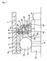
- Fig. 1 and Fig. 2 show a first example of the embodiment of the present invention.
- This example is characterized by making it difficult for steam or hot water that passes the mechanical seal 10 to get inside the rolling-bearing unit 6 including the plurality of rolling elements (balls) 15, by adequately regulating the shape and dimensions of the seal ring 13 and slinger 14 that are located in the middle section of the rotating shaft 3a further toward the outside than the mechanical seal 10 (see Fig. 4).
- the overall construction of the water pump and the construction and function of other sections are substantially the same as that of a conventional water pump, including the construction shown in Fig. 4, so drawings and explanations of identical sections will be omitted or simplified, and only the sections that are features of this invention or sections that were not previously explained will be explained here.
- rolling elements 15 are rotatively held by a retainer (not shown in the figures) between a deep groove-shaped outer-ring raceway 17, which is formed around the inner peripheral surface of an outer ring 16, and a deep groove-shaped inner-ring raceway 18, which is formed around the outer peripheral surface of the rotating shaft 3a.
- the outer peripheral edge of the seal ring 13 is fastened to an attachment groove 19 that is formed all the way around the inner peripheral surface on the inside end of the outer ring 16.
- This seal ring 13 comprises an elastic member 21 made of an elastomer such as rubber that is reinforced by a circular metal core 20.
- this elastic member 21 protrudes further outward in the radial direction than the outer peripheral edge of the metal core 20, and this outer peripheral edge of the elastic member 21 is fastened to the attachment groove 19.
- the elastic material 21 comprises a first seal lip 22 and a second seal lip 23.
- the first seal lip 22 is formed around the inner peripheral edge of the seal ring 13, so it comes into sliding contact all the way around the outer peripheral surface of the middle section of the rotating shaft 3a.
- the inner diameter of the first seal lip 22 in the free state is a little smaller than the outer diameter in the middle section of the rotating shaft 3a, and when the rotating shaft 3a is inserted into the inner-diameter side of the first seal lip 22, the inner peripheral edge of this first seal lip 22 comes in elastic contact all the way around the outer peripheral surface of the middle section of the rotating shaft 3a.
- the second seal lip 23 extends to the inside from a side surface of the elastic member 21 in a state where it is tilted outward in the radial direction toward its tip edge.
- the cross-sectional shape of this second seal lip 23 is a wedge shape where the width (thickness) dimension becomes smaller from the base toward the tip.
- the length dimension of the second seal lip 23 is such that it is at least two times and desirably at least 2.5 times the average thickness of the second seal lip 23.
- the tip edge of this second seal lip 23 comes in sliding contact all the way around the outside surface of the slinger 14 set forth later. In this state, the second seal lip 23 is bent (curled) such that it has a circular arc-shaped cross section.
- the aforementioned slinger 14 is thus fitted around and fixed to the middle section of the rotating shaft 3a in the section that is adjacent to the inside of the seal ring 13 and made of anti-corrosive metal plate such as stainless steel plate or steel plate for which anti-corrosion surface treatment has been performed such that at least the surface where the tip edge of the second seal lip 23 comes in contact does not corrode, and is formed by bending it generally into a ring shape having a crank-shaped cross section.
- the slinger 14 comprises: an inner-diameter-side cylindrical section 25 that is formed by bending at a right angle the inner peripheral edge of the circular section 24 to the inside in the axial direction; and an outer-diameter-side cylindrical section 26 that is similarly formed by bending at a right angle the outer peripheral edge to the outside in the axial direction.
- the roughness of the outside surface of the slinger 14, against which the tip edge of the second seal lip 23 comes in sliding contact in this way, is such that the arithmetic mean roughness Ra is from 0.2 ⁇ m to 2.0 ⁇ m or the maximum height Ry is from 0.8 ⁇ m to 8.0 ⁇ m.
- the amount of compression ⁇ of the second seal lip 23 (amount of elastic compression in the radial direction from the free state) when assembled as shown by the dot-dash line in Fig. 1, is at least 1/10 and up to 7/10 the height H of the second seal lip 23 in the free state as shown by the solid line in the figure (H/10 ⁇ ⁇ ⁇ 7H/10).
- this amount of elastic deformation ⁇ should be at least 2/10 and up to 5/10 the height H of the second seal lip 23 in the free state as shown by the solid line in the figure (2H/10 ⁇ ⁇ ⁇ 5H/10), and even more preferably at least 2/10 and up to 3/10 (2H/10 ⁇ ⁇ 3H/10).
- outer-diameter-side cylindrical portion 26 provided on the outer peripheral edge of the slinger 14, and the inner diameter R 26 of the outer-diameter-side cylindrical portion 26 is larger than the outer diameter D 23 of the second seal lip 23 under elastic deformation (R 26 > D 23 ), so that there is no interference nor rubbing between the tip end edge of the second seal lip 23 and the inner peripheral surface of the outer-diameter-side cylindrical portion 26.
- the second seal lip 23 is tilted outward in the radial direction toward the tip edge, it is possible to obtain an excellent prevention effect against the progression of foreign matter.
- foreign matter that is trying to get inside the rolling-bearing unit 6a reaches inside the space 27 on the radially outside of the second seal lip 23 through the gap between the tip end edge of the outer-diameter-side cylindrical portion 26 and the main portion of the seal ring 13, it presses against the outer peripheral surface of the second seal lip 23.
- This pressure force acts in the direction that pushes the tip edge of the second seal lip 23 against the outside surface of the slinger 14. Therefore, it becomes very difficult for gaps to occur in the section between the tip edge of the second seal lip 23 and the outside surface of the slinger 14.
- the second seal lip 23 swells due to the synergistic action of these two substances (steam and coolant water) and deforms in the circumferential direction as in a wave form, so even when gaps occur in a few places in the area of sliding contact between the tip edge of the second seal lip 23 and the outside surface of the slinger 14 and foreign matter tries to get inside the rolling-bearing unit 6a through the gaps, the foreign matter, before it can get into the rolling bearing unit 6a, is thrown outward in the radial direction by the centrifugal force that is applied to the foreign matter by contact with the outside surface of the slinger 14 that rotates together with the rotating shaft 3a.
- the inner diameter R 26 of the outer-diameter-side cylindrical portion 26 is larger than the outer diameter D 23 of the second seal lip 23 under elastic deformation (R 26 > D 23 ) in an arc-shape (curl shape) in cross section, so that there is a sufficient gap between the tip end edge of the second seal lip 23 and the inner peripheral surface of the outer-diameter-side cylindrical portion 26 to discharge the foreign matter. Therefore, the foreign matter is efficiently discharged and prevented from progressing into the rolling bearing unit 6.
- the amount of compression ⁇ of the second seal lip 23 is secured at least 1/10 the height H of the second seal lip 23 in the free state ( ⁇ ⁇ H/10), it is possible to secure the contact pressure at the area of sliding contact between the tip edge of the second seal lip 23 and the outside surface of the slinger 14 that occurs due to the elastic deformation of the second seal lip 23. Therefore, it is difficult for gaps to occur at the area of sliding contact, making it possible to improve the seal performance.
- the amount of compression ⁇ of the second seal lip 23 at least 2/10 the height H of the second seal lip 23 in the free state ( ⁇ ⁇ 2H/10), it is possible to even more effectively improve the seal performance.
- the arithmetic mean roughness Ra of the outside surface of the slinger 14 against which the tip edge of the second seal lip 23 comes in contact is regulated at from 0.2 ⁇ m to 2.0 ⁇ m, or the maximum height Ry is regulated at from 0.8 ⁇ m to 8.0 ⁇ m (by keeping the value of at least one of the arithmetic mean roughness Ra and the maximum height Ry within the aforementioned range, the surface is a smooth surface with little roughness), so the tip edge does not rub forcibly against the outside surface, and thus making it possible to keep wear of the tip edge to a minimum.
- the slinger 14 is made of anti-corrosive metal plate such that the surface of at least the section where the tip edge of the second seal lip 23 comes in sliding contact does not corrode, so roughness of the outside surface does not become worse due to corrosion, so that it is possible to maintain the function of preventing wear over a long period of time.
- Fig. 2 and Fig. 3 show a second and third example of the embodiment of the present invention.
- first seal lip 22 comes in sliding contact with the outer peripheral surface of the rotating shaft 3a
- second and third examples of the present invention there are two first seal lips 22, 22a that tilted in opposite directions from each other.
- the first seal lip 22a which tilts outward in the axial direction as it extends toward the inner-diameter side, functions well and has an excellent effect on preventing the grease inside the rolling-bearing unit from leaking out.
- the two seal lips 22, 22a come in sliding contact with the outer peripheral surface of the rotating shaft 3a.
- this invention makes it possible to improve the durability of a water pump without increasing cost and size of the water pump.
Landscapes
- Engineering & Computer Science (AREA)
- General Engineering & Computer Science (AREA)
- Mechanical Engineering (AREA)
- Sealing Of Bearings (AREA)
- Structures Of Non-Positive Displacement Pumps (AREA)
- Sealing With Elastic Sealing Lips (AREA)
Abstract
Description
Claims (3)
- A seal apparatus for a water pump provided between a non-rotating member having an inner peripheral surface and a rotating shaft of the water pump inserted into the non-rotating member and having an outer peripheral surface; comprising a seal ring having an outer peripheral edge fastened to the inner peripheral surface of the non-rotating member, and a slinger having an outer peripheral surface and a side surface, and fitted around the rotating shaft to block between the inner peripheral surface of the non-rotating member and the outer peripheral surface of the rotating shaft of the water pump, the seal ring comprising a first seal lip that comes in sliding contact with the outer peripheral surface of the rotating shaft or with the outer peripheral surface of the slinger that rotates together with the rotating shaft, and a second seal lip that has a tip edge which comes in sliding contact with the side surface of the slinger, and that is tilted outward in the radial direction toward the tip edge thereof, wherein the amount of compression of the second seal lip, which occurs when the tip edge of the second seal lip comes in contact with the side surface of the slinger, is at least 1/10 and up to 7/10 the height of the second seal lip in a free state, and the roughness of a side surface portion of the slinger with which the tip edge of the second seal lip comes in sliding contact is from 0.2 µm to 2.0 µm in the arithmetic mean Ra, or is from 0.8 µm to 8.0 µm in the maximum height Ry.
- A rotation-support apparatus for a water pump comprising: an outer ring having an inner peripheral surface formed with an outer ring raceway, a rotating shaft for the water pump having an outer peripheral surface formed with an inner ring raceway, a plurality of rolling elements rotatably located between the outer-ring raceway and inner-ring raceway, a seal ring having an outer peripheral edge fastened to the inner peripheral surface of the outer ring at one end thereof, and a slinger having a side surface and fitted around the rotating shaft, the seal ring having a first seal lip that comes in sliding contact with the outer peripheral surface of the rotating shaft or with the outer peripheral surface of a portion that rotates together with the rotating shaft, and a second seal lip that has a tip edge which comes in sliding contact with the side surface of the slinger, and that is tilted outward in the radial direction toward the tip edge thereof, wherein the amount of compression of the second seal lip, which occurs when the tip edge of the second seal lip comes in contact with the side surface of the slinger, is at least 1/10 and up to 7/10 the height of the second seal lip in a free state, and the roughness of a side surface portion of the slinger with which the tip edge of the second seal lip comes in sliding contact is from 0.2 µm to 2.0 µm in the arithmetic mean Ra, or is from 0.8 µm to 8.0 µm in the maximum height Ry.
- A water pump comprising a housing having an inner peripheral surface; an outer-ring raceway that is formed directly around the inner peripheral surface of this housing or formed around a separate outer ring around the inner peripheral surface of this housing, a rotating shaft having an outer peripheral surface formed with an inner-ring raceway, a plurality of rolling elements rotatably located between the outer-ring raceway and inner-ring raceway, a seal ring having an outer peripheral edge fastened to the inner peripheral surface of the outer ring at one end thereof, a slinger having a side surface and fitted around the rotating shaft, a pulley fastened to the rotating shaft at an outer end thereof, an impeller fastened to the rotating shaft at an inner end thereof, a mechanical seal provided between the inner peripheral surface of the housing and the outer peripheral surface of the rotating shaft and axially between the impeller and the slinger, and a space provided axially between the mechanical seal and the seal ring, the seal ring comprising a first seal lip that comes in sliding contact with the outer peripheral surface of the rotating shaft or with the outer peripheral surface of a portion that rotates together with the rotating shaft, and a second seal lip that has a tip edge which comes in sliding contact with the side surface of the slinger, and that is tilted outward in the radial direction toward the tip edge thereof, wherein the amount of compression of the second seal lip, which occurs when the tip edge of the second seal lip comes in contact with the side surface of the slinger, is at least 1/10 and up to 7/10 the height of the second seal lip in a free state, and the roughness of a side surface portion of the slinger with which where the tip edge of the second seal lip comes in sliding contact is from 0.2 µm to 2.0 µm in the arithmetic mean Ra, or is from 0.8 µm to 8.0 µm in the maximum height Ry.
Applications Claiming Priority (3)
| Application Number | Priority Date | Filing Date | Title |
|---|---|---|---|
| JP2001254363A JP2003065289A (en) | 2001-08-24 | 2001-08-24 | Water pump seal device, water pump rotation support device, and water pump |
| JP2001254363 | 2001-08-24 | ||
| PCT/JP2001/007305 WO2003018984A1 (en) | 2001-08-24 | 2001-08-27 | Seal device for water pump, rotation support device for water pump, and water pump |
Publications (3)
| Publication Number | Publication Date |
|---|---|
| EP1420154A1 true EP1420154A1 (en) | 2004-05-19 |
| EP1420154A4 EP1420154A4 (en) | 2005-02-09 |
| EP1420154B1 EP1420154B1 (en) | 2008-10-08 |
Family
ID=19082537
Family Applications (1)
| Application Number | Title | Priority Date | Filing Date |
|---|---|---|---|
| EP01958506A Expired - Lifetime EP1420154B1 (en) | 2001-08-24 | 2001-08-27 | Seal device for water pump, rotation support device for water pump, and water pump |
Country Status (9)
| Country | Link |
|---|---|
| US (1) | US6485256B1 (en) |
| EP (1) | EP1420154B1 (en) |
| JP (1) | JP2003065289A (en) |
| KR (1) | KR100558993B1 (en) |
| CN (1) | CN100374730C (en) |
| AT (1) | ATE410603T1 (en) |
| BR (1) | BR0117109A (en) |
| DE (1) | DE60136108D1 (en) |
| WO (1) | WO2003018984A1 (en) |
Cited By (1)
| Publication number | Priority date | Publication date | Assignee | Title |
|---|---|---|---|---|
| DE102006054743A1 (en) | 2006-11-21 | 2008-07-03 | Schaeffler Kg | Coolant pump i.e. water pump, for cooling circuit of internal combustion engine, has seals, where one of seal seals annular gap at side turned from pump wheel and includes occasional passage from gap to pump environment |
Families Citing this family (32)
| Publication number | Priority date | Publication date | Assignee | Title |
|---|---|---|---|---|
| US7066467B2 (en) * | 2000-12-28 | 2006-06-27 | Koyo Seiko Co., Ltd. | Sealing device for water pump bearings |
| US7419305B2 (en) * | 2001-08-24 | 2008-09-02 | Reliance Electric Technologies Llc | Sealing system for bearing assembly |
| JP2003074491A (en) * | 2001-09-04 | 2003-03-12 | Nsk Ltd | Water pump seal device, water pump rotation support device, and water pump |
| AU2003227434A1 (en) * | 2002-04-23 | 2003-11-10 | Nsk Ltd. | Seal device for water pump, rotation supporting device for water pump, and assembly method for water pump |
| JPWO2003091573A1 (en) * | 2002-04-23 | 2005-09-02 | 日本精工株式会社 | Water pump seal device, water pump rotation support device, water pump assembly method |
| ZA200302137B (en) * | 2002-08-21 | 2004-03-08 | Weir Envirotech Pty Ltd | Shielding a bearing and seal assembly from undesirable matter. |
| US6886833B1 (en) * | 2002-11-18 | 2005-05-03 | System Seals, Inc. | Seal for use in confined space and method |
| JP2005016603A (en) * | 2003-06-25 | 2005-01-20 | Nsk Ltd | Sealing device and rolling bearing unit with sealing device |
| DE10353304A1 (en) * | 2003-11-10 | 2005-06-09 | Kaco Gmbh + Co. Kg | Sealing ring, in particular radial shaft sealing ring |
| US20050167928A1 (en) * | 2004-02-04 | 2005-08-04 | Park Edward H. | Dynamic seal using vulcanization of fluorocarbon elastomers |
| US7367739B2 (en) * | 2004-08-02 | 2008-05-06 | Clark Equipment Company | Two component seal |
| US7658387B2 (en) | 2005-06-27 | 2010-02-09 | Freudenberg-Nok General Partnership | Reinforced elastomeric seal |
| JP5066834B2 (en) * | 2006-05-23 | 2012-11-07 | トヨタ自動車株式会社 | Alkaline storage battery |
| JP5180561B2 (en) * | 2007-11-20 | 2013-04-10 | 株式会社ジェイテクト | Sealing device, rolling bearing and wheel rolling bearing |
| WO2010043248A1 (en) * | 2008-10-14 | 2010-04-22 | Aktiebolaget Skf | Seal for rolling bearing, in particular for rolling bearing used in a wind turbine |
| KR101033492B1 (en) * | 2009-01-22 | 2011-05-12 | 김기산 | Placard post |
| JP5087607B2 (en) * | 2009-12-18 | 2012-12-05 | 日立オートモティブシステムズ株式会社 | Automotive water pump and bearing structure |
| JP2010261598A (en) * | 2010-08-24 | 2010-11-18 | Nsk Ltd | Sealing device and rolling bearing unit with sealing device |
| DE102010045671A1 (en) * | 2010-09-17 | 2012-03-22 | Carl Freudenberg Kg | sealing profile |
| AR087583A1 (en) * | 2011-08-16 | 2014-04-03 | Weir Floway Inc | BEARING ASSEMBLY FOR A VERTICAL TURBINE PUMP |
| JP5800148B2 (en) | 2011-12-21 | 2015-10-28 | Nok株式会社 | Engine rear seal |
| WO2013154644A2 (en) | 2012-01-19 | 2013-10-17 | Flowserve Management Company | Abeyance seal for high temperature, high pressure applications |
| JP6050080B2 (en) * | 2012-10-05 | 2016-12-21 | Ntn株式会社 | Sealed rolling bearing |
| KR20150074625A (en) * | 2013-12-24 | 2015-07-02 | 삼성테크윈 주식회사 | A supporter for compressing device core and a compressing device module comprising the supporter |
| GB2529807A (en) * | 2014-08-26 | 2016-03-09 | Skf Ab | Dynamic radial seal |
| US9951772B2 (en) * | 2015-06-18 | 2018-04-24 | Bitzer Kuehlmaschinenbau Gmbh | Scroll compressor with unmachined separator plate and method of making same |
| CN112815011A (en) * | 2017-06-30 | 2021-05-18 | 中山市盈科轴承制造有限公司 | Bearing sealing structure |
| DE102018104015A1 (en) * | 2018-02-22 | 2019-08-22 | Nidec Gpm Gmbh | Coolant pump with optimized bearing arrangement and improved heat balance |
| JP7118782B2 (en) * | 2018-07-10 | 2022-08-16 | 光洋シーリングテクノ株式会社 | sealing device |
| US11293551B2 (en) | 2018-09-30 | 2022-04-05 | ColdQuanta, Inc. | Break-seal system with breakable-membrane bridging rings |
| CN114718883A (en) * | 2022-04-21 | 2022-07-08 | 纪宇鹏 | Corrosion-resistant wear-resistant centrifugal pump |
| CN116480776A (en) * | 2023-05-06 | 2023-07-25 | 上海威逊机械连接件有限公司 | Sealing element, three-way pipe fitting, four-way pipe fitting and multi-way pipe fitting |
Family Cites Families (27)
| Publication number | Priority date | Publication date | Assignee | Title |
|---|---|---|---|---|
| DD107968A1 (en) * | 1972-05-23 | 1974-08-20 | ||
| US4073596A (en) | 1976-03-18 | 1978-02-14 | Kobe, Inc. | Lubricant cooling for high-speed pitot pump |
| US4171137A (en) | 1977-06-01 | 1979-10-16 | Ishikawajima-Harima Jukogyo Kabushiki Kaisha | Slinger arrangement for use with bearing of supercharger |
| JPS60167194A (en) * | 1984-02-09 | 1985-08-30 | Fujitsu Ltd | Semiconductor storage device |
| JPS60167194U (en) * | 1984-04-13 | 1985-11-06 | 日本精工株式会社 | water pump bearings |
| JPS62177921U (en) * | 1986-05-01 | 1987-11-12 | ||
| DE3616999A1 (en) * | 1986-05-21 | 1987-11-26 | Kugelfischer G Schaefer & Co | Seal, particularly for rolling-contact bearings |
| JP2921525B2 (en) | 1990-08-02 | 1999-07-19 | 大豊工業株式会社 | Sliding material |
| US5209499A (en) * | 1992-05-26 | 1993-05-11 | Mather Seal Company | Unitized polytetrafluoroethylene radial lip seal |
| US5558491A (en) | 1993-09-17 | 1996-09-24 | Andrews; Darrell G. | Unitized product seal for pumps |
| JPH08254213A (en) | 1995-03-17 | 1996-10-01 | Koyo Seiko Co Ltd | Sealing device for bearing for water pump |
| EP0735274B1 (en) | 1995-03-31 | 2000-12-27 | Aisin Seiki Kabushiki Kaisha | A liquid pump |
| JPH09229954A (en) | 1996-02-21 | 1997-09-05 | Nippon Seiko Kk | Combination seal ring with tone wheel |
| JPH09287619A (en) * | 1996-02-23 | 1997-11-04 | Nippon Seiko Kk | Rolling bearing unit with sealing device |
| JP4054855B2 (en) * | 1996-04-24 | 2008-03-05 | Ntn株式会社 | Sealing device |
| JP2809199B2 (en) | 1996-05-10 | 1998-10-08 | 日本精工株式会社 | Bearing seal device for water pump |
| US5890881A (en) | 1996-11-27 | 1999-04-06 | Alliedsignal Inc. | Pressure balanced turbocharger rotating seal |
| IT239862Y1 (en) | 1996-12-03 | 2001-03-13 | R F T S P A | SEALING COMPLEX FOR A ROTATING SHAFT, IN PARTICULAR OF A WATER PUMP OF AN AUTOMOTIVE ENGINE. |
| CN2309451Y (en) * | 1997-04-28 | 1999-03-03 | 中国船舶工业总公司第七研究院第七○八研究所 | Ring sealing device for pump |
| US6120243A (en) | 1997-05-15 | 2000-09-19 | Nok Corporation | Pump housing having a high pressure portion and a low pressure portion |
| US5927720A (en) | 1997-11-03 | 1999-07-27 | Carrier Corporation | Two-piece labyrinth seal for a centrifugal compressor balance piston |
| JP4004119B2 (en) * | 1997-11-20 | 2007-11-07 | 株式会社ジェイテクト | Water pump bearings |
| US6062815A (en) | 1998-06-05 | 2000-05-16 | Freudenberg-Nok General Partnership | Unitized seal impeller thrust system |
| US6149158A (en) * | 1998-06-30 | 2000-11-21 | Federal-Mogul World Wide, Inc. | Unitized oil seal with PTFE sealing disk split at radially outer edge and method of manufacture |
| AT409530B (en) | 1999-04-29 | 2002-09-25 | Tcg Unitech Ag | COOLING WATER PUMP FOR AN INTERNAL COMBUSTION ENGINE |
| JP2001020960A (en) * | 1999-07-08 | 2001-01-23 | Nachi Fujikoshi Corp | Unit seal bearing |
| JP3963246B2 (en) | 2000-02-01 | 2007-08-22 | Ntn株式会社 | Wheel bearing |
-
2001
- 2001-08-24 JP JP2001254363A patent/JP2003065289A/en active Pending
- 2001-08-27 EP EP01958506A patent/EP1420154B1/en not_active Expired - Lifetime
- 2001-08-27 BR BR0117109-7A patent/BR0117109A/en not_active IP Right Cessation
- 2001-08-27 AT AT01958506T patent/ATE410603T1/en not_active IP Right Cessation
- 2001-08-27 CN CNB018217788A patent/CN100374730C/en not_active Expired - Fee Related
- 2001-08-27 KR KR1020037007685A patent/KR100558993B1/en not_active Expired - Fee Related
- 2001-08-27 DE DE60136108T patent/DE60136108D1/en not_active Expired - Fee Related
- 2001-08-27 WO PCT/JP2001/007305 patent/WO2003018984A1/en not_active Ceased
- 2001-11-21 US US09/989,432 patent/US6485256B1/en not_active Expired - Fee Related
Cited By (1)
| Publication number | Priority date | Publication date | Assignee | Title |
|---|---|---|---|---|
| DE102006054743A1 (en) | 2006-11-21 | 2008-07-03 | Schaeffler Kg | Coolant pump i.e. water pump, for cooling circuit of internal combustion engine, has seals, where one of seal seals annular gap at side turned from pump wheel and includes occasional passage from gap to pump environment |
Also Published As
| Publication number | Publication date |
|---|---|
| EP1420154A4 (en) | 2005-02-09 |
| JP2003065289A (en) | 2003-03-05 |
| DE60136108D1 (en) | 2008-11-20 |
| BR0117109A (en) | 2005-01-04 |
| CN100374730C (en) | 2008-03-12 |
| ATE410603T1 (en) | 2008-10-15 |
| US6485256B1 (en) | 2002-11-26 |
| WO2003018984A1 (en) | 2003-03-06 |
| EP1420154B1 (en) | 2008-10-08 |
| KR20030059836A (en) | 2003-07-10 |
| KR100558993B1 (en) | 2006-03-10 |
| CN1484737A (en) | 2004-03-24 |
Similar Documents
| Publication | Publication Date | Title |
|---|---|---|
| EP1420154B1 (en) | Seal device for water pump, rotation support device for water pump, and water pump | |
| US6712580B2 (en) | Seal apparatus for a water pump, rotation-support apparatus for a water pump, and a water pump | |
| US20050062233A1 (en) | Seal device for water pump, rotation supporting device for water pump, and assembly method for water pump | |
| US7311308B2 (en) | Seal device for water pump, rotation supporting device for water pump and assembly method for water pump | |
| JP2890354B2 (en) | Bearing seal device for water pump | |
| JP4058568B2 (en) | Bearing device and method for assembling sealing member | |
| JP2003049848A (en) | Ball bearing for pulley support | |
| JPH09291942A (en) | Radial rolling bearings | |
| JP2809199B2 (en) | Bearing seal device for water pump | |
| JP3149863B2 (en) | Bearings for water pumps and water pumps for water-cooled engines of automobiles | |
| JP3897013B2 (en) | Water pump device | |
| JP2005325868A (en) | Rolling bearing unit with sealing device and rolling bearing with sealing plate | |
| JP2008064238A (en) | Water pump bearing | |
| JP2009024804A (en) | Sealing device | |
| JP3128062B2 (en) | Bearing seal device for water pump, bearing for water pump, and water pump for water-cooled engine of automobile | |
| JP2005048780A (en) | Seal ring for water pump, rotation support device for water pump and water pump | |
| JP2001032791A (en) | Water pump device | |
| JP2005048866A (en) | Rolling bearing | |
| JPH09228989A (en) | Bearing seal device for water pump | |
| JP2003247497A (en) | Water pump seal device, water pump rotation support device, and water pump | |
| JP2024003482A (en) | hub unit bearing | |
| JP2023159713A (en) | hub unit bearing | |
| JP2833606B2 (en) | Bearing seal device for water pump |
Legal Events
| Date | Code | Title | Description |
|---|---|---|---|
| PUAI | Public reference made under article 153(3) epc to a published international application that has entered the european phase |
Free format text: ORIGINAL CODE: 0009012 |
|
| 17P | Request for examination filed |
Effective date: 20030917 |
|
| AK | Designated contracting states |
Kind code of ref document: A1 Designated state(s): AT BE CH CY DE DK ES FI FR GB GR IE IT LI LU MC NL PT SE TR |
|
| AX | Request for extension of the european patent |
Extension state: AL LT LV MK RO SI |
|
| A4 | Supplementary search report drawn up and despatched |
Effective date: 20041223 |
|
| RIC1 | Information provided on ipc code assigned before grant |
Ipc: 7F 16J 15/32 B Ipc: 7F 04D 29/12 A Ipc: 7F 16C 33/76 B |
|
| 17Q | First examination report despatched |
Effective date: 20050303 |
|
| GRAP | Despatch of communication of intention to grant a patent |
Free format text: ORIGINAL CODE: EPIDOSNIGR1 |
|
| RTI1 | Title (correction) |
Free format text: SEAL DEVICE FOR WATER PUMP, ROTATION SUPPORT DEVICE FOR WATER PUMP, AND WATER PUMP |
|
| GRAS | Grant fee paid |
Free format text: ORIGINAL CODE: EPIDOSNIGR3 |
|
| GRAA | (expected) grant |
Free format text: ORIGINAL CODE: 0009210 |
|
| AK | Designated contracting states |
Kind code of ref document: B1 Designated state(s): AT BE CH CY DE DK ES FI FR GB GR IE IT LI LU MC NL PT SE TR |
|
| REG | Reference to a national code |
Ref country code: GB Ref legal event code: FG4D |
|
| REG | Reference to a national code |
Ref country code: CH Ref legal event code: EP |
|
| REG | Reference to a national code |
Ref country code: IE Ref legal event code: FG4D |
|
| REF | Corresponds to: |
Ref document number: 60136108 Country of ref document: DE Date of ref document: 20081120 Kind code of ref document: P |
|
| NLV1 | Nl: lapsed or annulled due to failure to fulfill the requirements of art. 29p and 29m of the patents act | ||
| PG25 | Lapsed in a contracting state [announced via postgrant information from national office to epo] |
Ref country code: AT Free format text: LAPSE BECAUSE OF FAILURE TO SUBMIT A TRANSLATION OF THE DESCRIPTION OR TO PAY THE FEE WITHIN THE PRESCRIBED TIME-LIMIT Effective date: 20081008 Ref country code: ES Free format text: LAPSE BECAUSE OF FAILURE TO SUBMIT A TRANSLATION OF THE DESCRIPTION OR TO PAY THE FEE WITHIN THE PRESCRIBED TIME-LIMIT Effective date: 20090119 |
|
| PG25 | Lapsed in a contracting state [announced via postgrant information from national office to epo] |
Ref country code: FI Free format text: LAPSE BECAUSE OF FAILURE TO SUBMIT A TRANSLATION OF THE DESCRIPTION OR TO PAY THE FEE WITHIN THE PRESCRIBED TIME-LIMIT Effective date: 20081008 Ref country code: PT Free format text: LAPSE BECAUSE OF FAILURE TO SUBMIT A TRANSLATION OF THE DESCRIPTION OR TO PAY THE FEE WITHIN THE PRESCRIBED TIME-LIMIT Effective date: 20090218 Ref country code: NL Free format text: LAPSE BECAUSE OF FAILURE TO SUBMIT A TRANSLATION OF THE DESCRIPTION OR TO PAY THE FEE WITHIN THE PRESCRIBED TIME-LIMIT Effective date: 20081008 |
|
| PG25 | Lapsed in a contracting state [announced via postgrant information from national office to epo] |
Ref country code: BE Free format text: LAPSE BECAUSE OF FAILURE TO SUBMIT A TRANSLATION OF THE DESCRIPTION OR TO PAY THE FEE WITHIN THE PRESCRIBED TIME-LIMIT Effective date: 20081008 Ref country code: DK Free format text: LAPSE BECAUSE OF FAILURE TO SUBMIT A TRANSLATION OF THE DESCRIPTION OR TO PAY THE FEE WITHIN THE PRESCRIBED TIME-LIMIT Effective date: 20081008 |
|
| PLBE | No opposition filed within time limit |
Free format text: ORIGINAL CODE: 0009261 |
|
| STAA | Information on the status of an ep patent application or granted ep patent |
Free format text: STATUS: NO OPPOSITION FILED WITHIN TIME LIMIT |
|
| PG25 | Lapsed in a contracting state [announced via postgrant information from national office to epo] |
Ref country code: SE Free format text: LAPSE BECAUSE OF FAILURE TO SUBMIT A TRANSLATION OF THE DESCRIPTION OR TO PAY THE FEE WITHIN THE PRESCRIBED TIME-LIMIT Effective date: 20090108 Ref country code: IT Free format text: LAPSE BECAUSE OF FAILURE TO SUBMIT A TRANSLATION OF THE DESCRIPTION OR TO PAY THE FEE WITHIN THE PRESCRIBED TIME-LIMIT Effective date: 20081008 |
|
| 26N | No opposition filed |
Effective date: 20090709 |
|
| PG25 | Lapsed in a contracting state [announced via postgrant information from national office to epo] |
Ref country code: MC Free format text: LAPSE BECAUSE OF NON-PAYMENT OF DUE FEES Effective date: 20090831 |
|
| REG | Reference to a national code |
Ref country code: CH Ref legal event code: PL |
|
| GBPC | Gb: european patent ceased through non-payment of renewal fee |
Effective date: 20090827 |
|
| PG25 | Lapsed in a contracting state [announced via postgrant information from national office to epo] |
Ref country code: LI Free format text: LAPSE BECAUSE OF NON-PAYMENT OF DUE FEES Effective date: 20090831 Ref country code: CH Free format text: LAPSE BECAUSE OF NON-PAYMENT OF DUE FEES Effective date: 20090831 |
|
| REG | Reference to a national code |
Ref country code: FR Ref legal event code: ST Effective date: 20100430 |
|
| REG | Reference to a national code |
Ref country code: IE Ref legal event code: MM4A |
|
| PG25 | Lapsed in a contracting state [announced via postgrant information from national office to epo] |
Ref country code: IE Free format text: LAPSE BECAUSE OF NON-PAYMENT OF DUE FEES Effective date: 20090827 Ref country code: FR Free format text: LAPSE BECAUSE OF NON-PAYMENT OF DUE FEES Effective date: 20090831 Ref country code: DE Free format text: LAPSE BECAUSE OF NON-PAYMENT OF DUE FEES Effective date: 20100302 |
|
| PG25 | Lapsed in a contracting state [announced via postgrant information from national office to epo] |
Ref country code: GR Free format text: LAPSE BECAUSE OF FAILURE TO SUBMIT A TRANSLATION OF THE DESCRIPTION OR TO PAY THE FEE WITHIN THE PRESCRIBED TIME-LIMIT Effective date: 20090109 |
|
| PG25 | Lapsed in a contracting state [announced via postgrant information from national office to epo] |
Ref country code: GB Free format text: LAPSE BECAUSE OF NON-PAYMENT OF DUE FEES Effective date: 20090827 |
|
| PG25 | Lapsed in a contracting state [announced via postgrant information from national office to epo] |
Ref country code: LU Free format text: LAPSE BECAUSE OF NON-PAYMENT OF DUE FEES Effective date: 20090827 |
|
| PG25 | Lapsed in a contracting state [announced via postgrant information from national office to epo] |
Ref country code: TR Free format text: LAPSE BECAUSE OF FAILURE TO SUBMIT A TRANSLATION OF THE DESCRIPTION OR TO PAY THE FEE WITHIN THE PRESCRIBED TIME-LIMIT Effective date: 20081008 |
|
| PG25 | Lapsed in a contracting state [announced via postgrant information from national office to epo] |
Ref country code: CY Free format text: LAPSE BECAUSE OF FAILURE TO SUBMIT A TRANSLATION OF THE DESCRIPTION OR TO PAY THE FEE WITHIN THE PRESCRIBED TIME-LIMIT Effective date: 20081008 |