EP1418627A2 - Solar cell module and edge face sealing member for same - Google Patents
Solar cell module and edge face sealing member for same Download PDFInfo
- Publication number
- EP1418627A2 EP1418627A2 EP03024397A EP03024397A EP1418627A2 EP 1418627 A2 EP1418627 A2 EP 1418627A2 EP 03024397 A EP03024397 A EP 03024397A EP 03024397 A EP03024397 A EP 03024397A EP 1418627 A2 EP1418627 A2 EP 1418627A2
- Authority
- EP
- European Patent Office
- Prior art keywords
- solar cell
- cell module
- edge face
- bodies
- sealing member
- Prior art date
- Legal status (The legal status is an assumption and is not a legal conclusion. Google has not performed a legal analysis and makes no representation as to the accuracy of the status listed.)
- Granted
Links
- 238000007789 sealing Methods 0.000 title claims abstract description 173
- 229920005989 resin Polymers 0.000 claims abstract description 40
- 239000011347 resin Substances 0.000 claims abstract description 40
- 229920001971 elastomer Polymers 0.000 claims abstract description 22
- 239000000806 elastomer Substances 0.000 claims abstract description 21
- 239000000654 additive Substances 0.000 claims abstract description 18
- 230000000996 additive effect Effects 0.000 claims abstract description 13
- 238000004383 yellowing Methods 0.000 claims abstract description 13
- HCWCAKKEBCNQJP-UHFFFAOYSA-N magnesium orthosilicate Chemical compound [Mg+2].[Mg+2].[O-][Si]([O-])([O-])[O-] HCWCAKKEBCNQJP-UHFFFAOYSA-N 0.000 claims abstract description 10
- 229910052919 magnesium silicate Inorganic materials 0.000 claims abstract description 10
- 235000019792 magnesium silicate Nutrition 0.000 claims abstract description 10
- 239000000391 magnesium silicate Substances 0.000 claims abstract description 10
- 239000000463 material Substances 0.000 claims abstract description 6
- 239000005038 ethylene vinyl acetate Substances 0.000 claims description 14
- 239000011521 glass Substances 0.000 claims description 12
- DQXBYHZEEUGOBF-UHFFFAOYSA-N but-3-enoic acid;ethene Chemical compound C=C.OC(=O)CC=C DQXBYHZEEUGOBF-UHFFFAOYSA-N 0.000 claims description 11
- 229920001200 poly(ethylene-vinyl acetate) Polymers 0.000 claims description 11
- 238000010276 construction Methods 0.000 claims description 10
- 229920001577 copolymer Polymers 0.000 claims description 8
- 229920002943 EPDM rubber Polymers 0.000 claims description 6
- 239000004793 Polystyrene Substances 0.000 claims description 4
- 239000003795 chemical substances by application Substances 0.000 claims description 4
- 229920002223 polystyrene Polymers 0.000 claims description 4
- RRHGJUQNOFWUDK-UHFFFAOYSA-N Isoprene Natural products CC(=C)C=C RRHGJUQNOFWUDK-UHFFFAOYSA-N 0.000 claims description 3
- 230000002265 prevention Effects 0.000 abstract description 3
- 238000004078 waterproofing Methods 0.000 description 29
- 230000008901 benefit Effects 0.000 description 4
- NINIDFKCEFEMDL-UHFFFAOYSA-N Sulfur Chemical compound [S] NINIDFKCEFEMDL-UHFFFAOYSA-N 0.000 description 3
- 230000015572 biosynthetic process Effects 0.000 description 3
- 230000015556 catabolic process Effects 0.000 description 3
- 238000006731 degradation reaction Methods 0.000 description 3
- 239000011593 sulfur Substances 0.000 description 3
- 229910052717 sulfur Inorganic materials 0.000 description 3
- 150000001412 amines Chemical class 0.000 description 2
- 230000037237 body shape Effects 0.000 description 2
- 150000001993 dienes Chemical class 0.000 description 2
- 235000012438 extruded product Nutrition 0.000 description 2
- 238000001125 extrusion Methods 0.000 description 2
- 238000003780 insertion Methods 0.000 description 2
- 230000037431 insertion Effects 0.000 description 2
- 238000004519 manufacturing process Methods 0.000 description 2
- -1 polypropylene - ethylene propylene Polymers 0.000 description 2
- 230000002195 synergetic effect Effects 0.000 description 2
- 229920003051 synthetic elastomer Polymers 0.000 description 2
- 239000005061 synthetic rubber Substances 0.000 description 2
- 238000012360 testing method Methods 0.000 description 2
- 230000032683 aging Effects 0.000 description 1
- XAGFODPZIPBFFR-UHFFFAOYSA-N aluminium Chemical compound [Al] XAGFODPZIPBFFR-UHFFFAOYSA-N 0.000 description 1
- 229910052782 aluminium Inorganic materials 0.000 description 1
- 229910021417 amorphous silicon Inorganic materials 0.000 description 1
- 238000005452 bending Methods 0.000 description 1
- 230000000694 effects Effects 0.000 description 1
- 239000006261 foam material Substances 0.000 description 1
- 230000005484 gravity Effects 0.000 description 1
- 238000003475 lamination Methods 0.000 description 1
- 230000014759 maintenance of location Effects 0.000 description 1
- 238000000034 method Methods 0.000 description 1
- 229910021421 monocrystalline silicon Inorganic materials 0.000 description 1
- 239000003921 oil Substances 0.000 description 1
- 230000000704 physical effect Effects 0.000 description 1
- 229920003023 plastic Polymers 0.000 description 1
- 239000004033 plastic Substances 0.000 description 1
- 229910021420 polycrystalline silicon Inorganic materials 0.000 description 1
- 238000012805 post-processing Methods 0.000 description 1
- 239000005060 rubber Substances 0.000 description 1
- 239000003566 sealing material Substances 0.000 description 1
- 238000003860 storage Methods 0.000 description 1
- 239000000126 substance Substances 0.000 description 1
- 125000000383 tetramethylene group Chemical group [H]C([H])([*:1])C([H])([H])C([H])([H])C([H])([H])[*:2] 0.000 description 1
- 238000002207 thermal evaporation Methods 0.000 description 1
- 239000004636 vulcanized rubber Substances 0.000 description 1
- XLYOFNOQVPJJNP-UHFFFAOYSA-N water Substances O XLYOFNOQVPJJNP-UHFFFAOYSA-N 0.000 description 1
Images


Classifications
-
- H—ELECTRICITY
- H02—GENERATION; CONVERSION OR DISTRIBUTION OF ELECTRIC POWER
- H02S—GENERATION OF ELECTRIC POWER BY CONVERSION OF INFRARED RADIATION, VISIBLE LIGHT OR ULTRAVIOLET LIGHT, e.g. USING PHOTOVOLTAIC [PV] MODULES
- H02S20/00—Supporting structures for PV modules
-
- H—ELECTRICITY
- H02—GENERATION; CONVERSION OR DISTRIBUTION OF ELECTRIC POWER
- H02S—GENERATION OF ELECTRIC POWER BY CONVERSION OF INFRARED RADIATION, VISIBLE LIGHT OR ULTRAVIOLET LIGHT, e.g. USING PHOTOVOLTAIC [PV] MODULES
- H02S30/00—Structural details of PV modules other than those related to light conversion
- H02S30/10—Frame structures
-
- Y—GENERAL TAGGING OF NEW TECHNOLOGICAL DEVELOPMENTS; GENERAL TAGGING OF CROSS-SECTIONAL TECHNOLOGIES SPANNING OVER SEVERAL SECTIONS OF THE IPC; TECHNICAL SUBJECTS COVERED BY FORMER USPC CROSS-REFERENCE ART COLLECTIONS [XRACs] AND DIGESTS
- Y02—TECHNOLOGIES OR APPLICATIONS FOR MITIGATION OR ADAPTATION AGAINST CLIMATE CHANGE
- Y02B—CLIMATE CHANGE MITIGATION TECHNOLOGIES RELATED TO BUILDINGS, e.g. HOUSING, HOUSE APPLIANCES OR RELATED END-USER APPLICATIONS
- Y02B10/00—Integration of renewable energy sources in buildings
- Y02B10/10—Photovoltaic [PV]
-
- Y—GENERAL TAGGING OF NEW TECHNOLOGICAL DEVELOPMENTS; GENERAL TAGGING OF CROSS-SECTIONAL TECHNOLOGIES SPANNING OVER SEVERAL SECTIONS OF THE IPC; TECHNICAL SUBJECTS COVERED BY FORMER USPC CROSS-REFERENCE ART COLLECTIONS [XRACs] AND DIGESTS
- Y02—TECHNOLOGIES OR APPLICATIONS FOR MITIGATION OR ADAPTATION AGAINST CLIMATE CHANGE
- Y02E—REDUCTION OF GREENHOUSE GAS [GHG] EMISSIONS, RELATED TO ENERGY GENERATION, TRANSMISSION OR DISTRIBUTION
- Y02E10/00—Energy generation through renewable energy sources
- Y02E10/50—Photovoltaic [PV] energy
Definitions
- the present invention relates to a solar cell module capable of being installed on roof portions of residential buildings or the like and to an edge face sealing member for same, and in particular, pertains to an improvement for ensuring watertightness between solar cell module body or bodies and frame body or bodies supporting same.
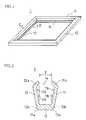
- FIG. 6 (a) is a plan view of solar cell module 2; FIG. 6 (b) indicating the view from arrow B at FIG. 6 (a), and FIG. 6 (c) indicating the view from arrow C at FIG. 6 (a).
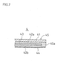
- solar cell module body 4 The integrally laminated superstrate construction of solar cell module body 4, as indicated by the partial enlarged view of edge portion 45 thereof shown in FIG. 7-wherein light-receiving-surface sealing resin layer(s) 42a comprising ethylene vinyl acetate (EVA), solar cell(s) 43 formed from polycrystalline silicon, back-surface sealing resin layer(s) 42b comprising ethylene vinyl acetate (EVA), and weather-resistant back-surface sealing film(s) 44 are laminated in order over (or beneath, as shown in the drawing) light-receiving glass surface(es) 41 constituting the front surface thereof-is known.
- the solar cell module body 4 may take the form of a rectangular sheet and its weather-resistance may be assured.
- the foregoing solar cell(s) 43 may be formed from monocrystalline silicon and/or amorphous silicon and/or the like.
- frame body 5- which retains the four sides of the foregoing solar cell module body 4-comprises upper frame element(s) 51, lower frame element(s) 52, and pair(s) of left and right side edge frame elements 53 and 54, these frame elements 51, 52, 53, and 54 being assembled together in integral fashion to form a frame-like structure.
- FIG. 8 shows the region at which lower frame element 52 and right side edge frame element 54 are assembled together.
- Frame elements 51, 52, 53, and 54 are respectively formed by aluminum extrusion.
- Upper frame element 51 retains the edge rim of solar cell module body 4 at the side thereof nearest the residence roof peak.
- Lower frame element 52 retains the edge rim of solar cell module body 4 at the side thereof nearest the residence eaves.
- Side edge frame elements 53 and 54 respectively retain both the left and the right side rim of solar cell module body 4, and also join together the two edge rims of upper frame element 51 and lower frame element 52.
- FIG. 9 will be used to describe cross-sectional shape of side edge frame element 54. Note that, in the description of cross-sectional shape which follows, the left side in FIG. 9 is taken to be the outside, constituting the outer rim of solar cell module 2; and the right side in the drawing is taken to be the inside, i.e., the side at which solar cell module body 4 is supported.
- side edge frame element 54 is provided with frame main body 54a having closed rectangular cross-section, and is also provided with bent extension region 54b which extends upward from the outside edge (left edge in the drawing) at the top face of this frame main body 54a and thereafter bends toward the inside (right side in the drawing).
- flange 54f which abuts the bottom face of solar cell module body 4, is disposed so as to project from the inside edge (the edge on the right side in the drawing) of top face 54c of frame main body 54a.
- the width dimension (the dimension in the vertical direction in FIG. 9) of this groove 54e is set so as to be slightly larger than the thickness dimension of solar cell module body 4.
- extension 54g which extends slightly in a horizontal direction before bending upward.
- reference numeral 52h in FIG. 8 indicates screw-receiving portion(s), having screw channels(s), provided at lower frame element 52; and reference numeral 54h indicates screw clearance hole(s) which are provided at side rim frame element 54 opposite these screw-receiving portion(s) 52h.
- FIG. 10 shows an example of a conventional waterproofing structure for achieving watertightness between solar cell module body 4 and frame body 5, the structure being such that tape-like waterproofing member 61 is inserted in the space between solar cell module body 4 and frame body 5. That is, waterproofing member 61 is arranged so as to enshroud the open portion(s) of groove 54e of side edge frame element 54.
- This waterproofing member 61 is a sheet-like member formed from EPDM or other such foam material, and is disposed so as to straddle flange 54f from horizontal portion 54d of extension region 54b of side edge frame element 54. Furthermore, this waterproofing member 61 is made to adhere to the tip portion of this flange 54f (region I at FIG. 10 (a)).
- this edge portion is in fact a free edge.
- the thickness dimension of this waterproofing member 61 is set so as to be slightly larger than a dimension which is one half of the value obtained by subtracting the thickness dimension of solar cell module body 4 from the width dimension (the dimension in the vertical direction at FIG. 10 (a)) of groove 54e of side edge frame element 54.
- This waterproofing member 61 might for example be formed from butylene rubber.
- waterproofing member 61 is provided at one side edge frame element 54
- waterproofing member(s) 61, 62, 62 are provided in like fashion at the other side edge frame element 53; and moreover, waterproofing member(s) 61 are provided in like fashion at upper frame element 51 and lower frame element 52.
- This waterproofing member 61 is captured by frames 51, 52, 53, and 54 at the same time that solar cell module body 4 is captured thereby.
- description will be carried out taking operation with respect to how the side edge portion of solar cell module body 4 is captured within side edge frame 54 to be representative of the others.
- waterproofing member 61 is deformed as a result of pressure from solar cell module body 4.
- deformation of waterproofing member 61 is such that the free-edge side (the portion at the top at FIG. 10 (b)) of waterproofing member 61 is pressed by solar cell module body 4 against the interior of groove 54e, waterproofing member 61 being deformed so as to wrap around the outside perimeter portion of solar cell module body 4 in parallel fashion with respect to the inside surface of this groove 54e. Waterproofing member(s) 61 are therefore respectively present between the inside surface of groove 54e and the top surface and the bottom surface of the outside perimeter portion of solar cell module body 4.
- the thickness dimension of waterproofing member 61 is set so as to be slightly larger than one half of the value obtained by subtracting the thickness dimension of solar cell module body 4 from the width dimension (the dimension in the vertical direction at FIG. 10 (b)) of groove 54e, waterproofing member 61 will upon completion of this capturing operation be compressed between the outside surface (at both the top and the bottom) of solar cell module body 4 and the inside surface of groove 54e.
- a waterproofing structure having the foregoing constitution will make it possible to ensure watertightness between solar cell module body 4 and the frame body 5 which supports same.
- waterproofing member 61 is bent unnaturally at the comer portion(s) of frame body 5, it has been necessary to have another waterproofing member made available for such portion(s), and it has been difficult to adequately ensure watertightness at especially the comer portion(s).
- the present invention was conceived in order to solve such problems, it being an object thereof to provide a solar cell module and an edge face sealing member for same which will ensure watertightness (i.e., sealing) through a simple structure designed to facilitate operations during solar cell module assembly and which is capable of definitive prevention of solar cell module body yellowing.
- One or more embodiments of the present invention is or are predicated upon a solar cell module construction which is such that one or more solar cell module bodies are captured within one or more frame bodies.
- a structure may be adopted such that one or more edge face sealing members, frame-like in shape and formed in more or less parallel fashion with respect to one or more outer shapes of solar cell module body or bodies, is or are prepared; such edge face sealing member or members capturing at least one of the solar cell module body or bodies along substantially the entire edge portion perimeter thereof, and with these in this state, these being captured within at least one of the frame body or bodies.
- edge face sealing member or members may be roughly c-shaped in cross-section, may comprise one or more upper sealing regions abutting one or more front surfaces of solar cell module body or bodies, may further comprise one or more lower sealing regions abutting one or more back surfaces of solar cell module body or bodies, and may further comprise one or more side sealing regions abutting one or more edge faces of solar cell module body or bodies.
- edge face sealing member or members may be such that lower sealing region or regions is or are longer than upper sealing region or regions.
- Lower sealing region(s) being the portion(s) abutting back surface(s) of solar cell module body or bodies, because reception of light by solar cell(s) is not interfered with, there will be no problem even where it or they extend beyond frame body or bodies.
- Causing lower sealing region(s) to be made long in this manner makes it possible to prevent edge face sealing member(s) from easily falling out of solar cell module body or bodies.
- frame body shape it being possible for example to employ the conventional frame body shape shown in FIG. 9. At the frame body shown in FIG.
- flange 54f being the portion abutting lower sealing region(s), is longer than horizontal portion 54d of bent extension region 54b abutting lower sealing region(s), forming same such that its length matches that of this horizontal portion 54d will also be preferred from the standpoint of watertightness.
- projections may be respectively formed on facing surfaces of upper sealing region(s) and lower sealing region(s). More specifically, such projections may comprise one or more single-rib or multiple-rib regions formed in more or less parallel fashion with respect to one or more perimeter edge portions of solar cell module body or bodies. With perimeter edge portion(s) of solar cell module body or bodies captured by sealing members), when such sealing member portion(s) are captured within groove(s) of frame body or bodies, because formation of such projections makes it possible for sealing member(s) to be compressed by groove(s) of frame body or bodies and for projection(s) to be squashed by top surface(s) and bottom surface(s) of solar cell module body or bodies, producing intimate contact therebetween, definitive sealing of edge face(s) of solar cell module body or bodies is permitted.
- tip portion(s) of upper sealing region(s) and lower sealing region(s) may be disposed in inclined fashion at respectively facing sealing region surfaces.
- tip portion(s) of upper sealing region(s) and lower sealing region(s) can also be made to press against top surface(s) and bottom surface(s) of solar cell module body or bodies, producing intimate contact therebetween, synergistic operation in combination with projection(s) permits more definitive sealing of edge face(s) of solar cell module body or bodies.
- sealing structure is applied to solar cell module body or bodies of integrally laminated superstrate construction such that laminated in order over one or more light-receiving glass surfaces constituting one or more front surfaces there are one or more light-receiving-surface sealing resin layers comprising ethylene vinyl acetate, one or more solar cells, one or more back-surface sealing resin layers comprising ethylene vinyl acetate, and one or more weather-resistant back-surface sealing films.
- the present invention is not limited to application in the context of superstrate structures, it also being possible to apply same for example to see-through-type solar cell modules wherein both the top and bottom surfaces are formed from glass.
- material(s) making up edge face sealing member(s) be polypropylenic and/or polystyrenic elastomer resin(s); more specifically, it is still more preferred that PP-EPDM (polypropylene - ethylene propylene diene copolymeric synthetic rubber) copolymer be for example employed as polypropylenic elastomer resin(s), and/or that polystyrene -isoprene copolymer be for example employed as polystyrenic elastomer resin(s).
- PP-EPDM polypropylene - ethylene propylene diene copolymeric synthetic rubber
- such elastomer resin(s) comprise one or more additives of porous structure preventing yellowing of sealing resin layer or layers. More specifically, it is preferred that additive or additives comprise magnesium silicate.
- magnesium silicate being cited as a prominent example thereof, changes in color due to low-molecular-weight oils present within elastomer(s) and/or yellowing of ethylene vinyl acetate (EVA) due to trace amounts of sulfur or other such inorganic substances can be prevented as a result of the absorptive action thereof, consequently making it possible to prevent yellowing of perimeter rim portions of solar cell module body or bodies.
- additive(s) comprising ultraviolet-resistant agent(s) (e.g., hindered amine(s)) will make it possible to prevent degradation due to ultraviolet light.
- ultraviolet-resistant agent(s) e.g., hindered amine(s)
- FIG. 1 is an oblique view of the entirety of an edge face sealing member associated with a first embodiment of the present invention.
- FIG. 2 is a cross-sectional view of section D-D in FIG. 1.
- FIG. 3 (a) is a partial enlarged sectional view showing how an edge face sealing member of the first embodiment captures an edge portion of a solar cell module body
- FIG. 3 (b) is a partial enlarged sectional view showing how the edge portion of the solar cell module body as shown at FIG. 3 (a) is captured within a groove portion of a frame body.
- FIG. 4 is a sectional view of an edge face sealing member associated with a second embodiment of the present invention.
- FIG. 5 is a partial enlarged sectional view showing, where an edge portion of a solar cell module body is captured by an edge face sealing member, how this is moreover captured by a groove portion of a frame body.
- FIG. 6 (a) is a plan view of a solar cell module; FIG. 6 (b) indicating the view from arrow B at FIG. 6 (a), and FIG. 6 (c) indicating the view from arrow C at FIG. 6 (a).
- FIG. 7 is a partial enlarged sectional view showing an edge portion of solar cell module body of superstrate construction.
- FIG. 8 is an oblique exploded view of region III in FIG. 6.
- FIG. 9 is a sectional view of a frame body.
- FIG. 10 (a) is a sectional view showing arrangement of a waterproofing member
- FIG. 10 (b) is a sectional view showing deformation of a waterproofing member.
- FIG. 1 is an oblique view of the entirety of an edge face sealing member 1 associated with a first embodiment of the present invention
- FIG. 2 is a cross-sectional view of section D-D in FIG. 1.
- the description below is carried out in terms of a solar cell module body employing superstrate structure such as that of solar cell module body 4 shown in FIG. 7, and in terms of a frame body employing structure such as that of frame body 5 shown in FIG. 9.
- This edge face sealing member 1 which is frame-like in shape and is formed in more or less parallel fashion with respect to the outer shape of solar cell module body 4 shown in FIG. 6, captures solar cell module body 4 along substantially the entire edge portion 45 perimeter thereof, and with these in this state, this is captured within the frames 51, 52, 53 and 54 of frame body 5 (see FIG. 7).
- this edge face sealing member 1 is roughly c-shaped in cross-section and/or roughly u-shaped in cross-section, and comprises upper sealing region 11 abutting light-receiving glass surface 41 which constitutes the front surface of solar cell module body 4; lower sealing region 12 abutting weather-resistant back-surface sealing film 44 of solar cell module body 4; and side sealing region 13 abutting edge face 45a (see FIG. 7) of solar cell module body 4.
- This upper sealing region 11, this lower sealing region 12, and this side sealing region 13 form groove recess 14 which captures edge portion 45 of solar cell module body 4.
- upper sealing region 11 and lower sealing region 12 are disposed so as to open somewhat to the outside therefrom at either side from edge portions 13a, 13a of side sealing region 13, and tip portions 11a and 12a are formed in bent fashion so as to be inclined toward each other, i.e., toward groove recess 14.
- Distance T between these two tip portions 11a and 12a is roughly the same as or is somewhat less than the thickness of edge portion 45 of solar cell module body 4.
- edge portions 13a, 13a of side sealing region 13 are formed so as to be curved in order to facilitate capture thereof by frame body 5.
- diagonal cuts may be made therein so as to produce chamfered surfaces 13b, 13b.
- projections 11b, 12b are Respectively formed on facing surfaces of upper sealing region 11 and lower sealing region 12, formed as described above.
- projections 11b, 12b may take the form of single-rib and/or multiple-rib regions (two ribs being formed in the present first embodiment) formed in more or less parallel fashion with respect to perimeter edge portions (sides) of solar cell module body 4, i.e., in more or less parallel fashion with respect to the long direction of groove recess 14.
- FIG. 3 (a) shows how edge face sealing member 1, constituted as described above, captures edge portion 45 of solar cell module body 4.
- edge face sealing member 1 will not easily slip off of edge portion 45 of solar cell module body 4.
- edge face sealing member 1 is deformed in parallel fashion with respect to the inside surface of groove 54e as shown at FIG. 3 (b), projections 11b, 12b (not shown) and tip portions 11a and 12a of upper sealing region 11 and lower sealing region 12 being squashed and coming into intimate contact with light-receiving glass surface 41 and weather-resistant back-surface sealing film 44 of solar cell module body 4.
- side sealing region 13 of edge face sealing member 1 likewise comes in intimate contact with edge face 45a of solar cell module body 4, resulting in manufacture of a solar cell module in which edge face 45a of solar cell module body 4 is completely sealed.
- FIG. 4 is a sectional view of edge face sealing member 1A associated with a second embodiment of the present invention.
- Edge face sealing member 1A of the present second embodiment differs from edge face sealing member 1 of the foregoing first embodiment in that lower sealing region 12A abutting weather-resistant back-surface sealing film 44 of solar cell module body 4 is formed so as to be longer than upper sealing region 11 abutting light-receiving glass surface 41 of solar cell module body 4, the constitution thereof being in other respects similar to that of edge face sealing member 1 of the foregoing first embodiment. Accordingly, where components are identical to those at edge face sealing member 1 of the first embodiment, identical reference numerals will be used and detailed description thereof will be omitted.
- lower sealing region 12A such that it is longer than upper sealing region 11 is that, as shown in FIG. 9, flange 54f is provided at the inside edge of top face 54c of frame main body 54a, and this surface is longer than horizontal portion 54d of bent extension region 54b by an amount corresponding to this flange 54f.
- Lower sealing region 12A is therefore formed such that the length thereof more or less matches the length from the basal edge portion of top face 54c (the region at which it is connected to bent extension region 54b) to the tip of flange 54f.
- FIG. 5 is a partial enlarged sectional view showing a solar cell module in which, where edge portion 45 of solar cell module body 4 is captured by edge face sealing member 1A constituted as described above, this is moreover captured by frame body 5.
- edge face sealing member 1 is deformed in parallel fashion with respect to the inside surface of groove 54e of frame body 5, projections 11b, 12b (not shown) and tip portions 11a and 12a of upper sealing region 11 and lower sealing region 12A being squashed and coming into intimate contact with light-receiving glass surface 41 and weather-resistant back-surface sealing film 44 of solar cell module body 4.
- lower sealing region 12A is brought into intimate contact therewith over the entirety, more or less, of flange 54f and top face 54c of groove 54e, watertightness at the back surface of solar cell module body 4 is improved.
- side sealing region 13 of edge face sealing member 1 likewise comes in intimate contact with edge face 45a of solar cell module body 4, resulting in manufacture of a solar cell module in which edge face 45a of solar cell module body 4 is completely sealed.
- solar cell module body 4 which is of superstrate construction, is such that, in contrast to light-receiving glass surface 41 at the front surface thereof, the back surface thereof is thin weather-resistant film 44, where integral lamination is carried out the back surface will be forcibly pulled upon such that it becomes somewhat inclined.
- lower sealing region 12A is made long as in the present second embodiment, this will also have the advantage that it will be possible to cause edge portion 45 of solar cell module body 4 to be definitively captured by edge face sealing member 1A, any such inclination having little effect thereon. Or stating this conversely, this has the benefit of also preventing edge face sealing member 1A from slipping off of solar cell module body 4.
- material(s) making up edge face sealing member(s) 1, 1 A be polypropylenic and/or polystyrenic elastomer resin(s). More specifically, it is still more preferred that PP-EPDM (polypropylene - ethylene propylene diene copolymeric synthetic rubber) copolymer be for example employed as polypropylenic elastomer resin(s), and/or that polystyrene - isoprene copolymer be for example employed as polystyrenic elastomer resin(s).
- PP-EPDM polypropylene - ethylene propylene diene copolymeric synthetic rubber
- Polypropylenic and polystyrenic elastomer resins possess characteristics such as lightness in weight due to low specific gravity, manufacturability and recyclability, designability with respect to coloration, weather resistance (retention of physical properties over long periods), sealability, aging as a result of heat, flexibility at low temperature (-40° C), dimensional stability of extruded product, flexibility with respect to design of cross-section of extruded product, thermal deposition, and so forth.
- such elastomer resin(s) may in accordance with the present invention be made to comprise additive(s) of porous structure which will prevent yellowing of sealing resin (EVA) layer(s). More specifically, magnesium silicate may be employed as additive.
- elastomer resin(s) By thus causing elastomer resin(s) to comprise additive(s) of porous structure, magnesium silicate being cited as a prominent example thereof, sulfur present within sealing resin(s) (EVA) in solar cell module body or bodies can be absorbed, as a result of which yellowing of perimeter edge portions of solar cell module body or bodies can be prevented.
- EVA sealing resin
- edge face sealing members 1, 1A comprising PP-EPDM containing on the order of 1 to 1.5% magnesium silicate, and, after assembling same such that solar cell module bodies 4 employing EVA sealing resin(s) were captured by edge face sealing members 1, 1 A thus prepared, carried out high-temperature, high-humidity storage testing pursuant to JISC 8917.
- yellowing of EVA sealing resin(s) at edge portions 54 of solar cell module bodies 4 was not observed even after 1000 hours at 85 percent humidity.
- additive(s) comprising ultraviolet-resistant agent(s) (e.g., hindered amine(s)) will make it possible to prevent degradation due to ultraviolet light.
- ultraviolet-resistant agent(s) e.g., hindered amine(s)
- one or more embodiments of the present invention is or are predicated upon a solar cell module construction which is such that one or more solar cell module bodies are captured within one or more frame bodies.
- a structure may be adopted such that one or more edge face sealing members, frame-like in shape and formed in more or less parallel fashion with respect to one or more outer shapes of solar cell module body or bodies, is or are prepared; such edge face sealing member or members capturing at least one of the solar cell module body or bodies along substantially the entire edge portion perimeter thereof, and with these in this state, these being captured within at least one of the frame body or bodies.
- edge face sealing member(s) capture solar cell module body or bodies along substantially the entire edge portion perimeter thereof, definitive sealing of solar cell module body or bodies is permitted, permitting definitive prevention of entry by water. Furthermore, because edge face sealing member(s) which is or are c-shaped and/or u-shaped in cross-section is or are made to capture solar cell module body or bodies, and while in this state, these are then caused to be captured by frame body or bodies, it is possible to rest assured that edge face sealing member(s) will not slip when caused to be captured by frame body or bodies, and moreover, ease of operations with respect to the capturing step is improved.
- edge face sealing member(s) Furthermore, causing lower sealing region(s) of edge face sealing member(s) to be formed so as to be longer than upper sealing region(s) thereof makes it possible to prevent edge face sealing member(s) from easily falling out of solar cell module body or bodies, and also improves watertightness at the back surface of solar cell module body or bodies.
- edge face sealing member(s) are captured within groove(s) of frame body or bodies, because formation of projections on facing surfaces of upper sealing region(s) and lower sealing region(s) makes it possible for edge face sealing member(s) to be compressed by groove(s) of frame body or bodies and for projection(s) to be squashed by top surface(s) and bottom surface(s) of solar cell module body or bodies, producing intimate contact therebetween, definitive sealing of edge face(s) of solar cell module body or bodies is permitted.
- tip portion(s) of upper sealing region(s) and lower sealing region(s) so as to incline toward recess(es)
- tip portion(s) of upper sealing region(s) and lower sealing region(s) can also be made to press against top surface(s) and bottom surface(s) of solar cell module body or bodies, producing intimate contact therebetween
- synergistic operation in combination with projection(s) permits more definitive sealing of edge face(s) of solar cell module body or bodies.
- polypropylenic and/or polystyrenic elastomer resin(s), and more specifically, PP-EPDM copolymer(s) and/or polystyrene - isoprene copolymer(s), is or are employed as material(s) making up edge face sealing member(s).
- elastomer resin(s) contain magnesium silicate serving as additive(s) of porous structure preventing yellowing of sealing resin layer(s).
- magnesium silicate being cited as a prominent example thereof, sulfur present within EVA can be absorbed, as a result of which yellowing of perimeter rim portions of solar cell module body or bodies can be prevented.
- employment of additive(s) comprising ultraviolet-resistant agent(s) will make it possible to prevent degradation due to ultraviolet light.
Abstract
Description
Claims (15)
- A solar cell module edge face sealing member for, where solar cell module construction is such that one or more solar cell module bodies are captured within one or more frame bodies, sealing one or more gaps between at least one of the solar cell module body or bodies and at least one of the frame body or bodies;
the edge face sealing member being frame-like in shape and formed in more or less parallel fashion with respect to one or more outer shapes of at least one of the solar cell module body or bodies; and
the edge face sealing member capturing at least one of the solar cell module body or bodies along substantially the entire edge portion perimeter thereof, and with these in this state, these being captured within at least one of the frame body or bodies. - A solar cell module edge face sealing member according to claim 1 wherein:the edge face sealing member is roughly c-shaped in cross-section and/or roughly u-shaped in cross-section;the edge face sealing member comprises one or more upper sealing regions abutting one or more front surfaces of at least one of the solar cell module body or bodies;the edge face sealing member further comprises one or more lower sealing regions abutting one or more back surfaces of at least one of the solar cell module body or bodies; andthe edge face sealing member further comprises one or more side sealing regions abutting one or more edge faces of at least one of the solar cell module body or bodies.
- A solar cell module edge face sealing member according to claim 2 wherein at least one of the lower sealing region or regions is longer than at least one of the upper sealing region or regions.
- A solar cell module edge face sealing member according to claim 2 or 3 wherein:at least one surface of at least one of the upper sealing region or regions and at least one surface of at least one of the lower sealing region or regions face each other; andone or more projections are formed on each of at least two respectively facing surfaces among the upper and lower sealing region surfaces which face each other.
- A solar cell module edge face sealing member according to claim 4 wherein at least one of the projection or projections comprises one or more single-rib or multiple-rib regions formed in more or less parallel fashion with respect to one or more perimeter edge portions of at least one of the solar cell module body or bodies.
- A solar cell module edge face sealing member according to claim 4 wherein one or more tip portions of at least one of the lower sealing region or regions and at least one of the upper sealing region or regions are disposed in inclined fashion at respectively facing sealing region surfaces.
- A solar cell module edge face sealing member according to claim 1 wherein at least one of the solar cell module body or bodies is of integrally laminated superstrate construction such that laminated in order over one or more light-receiving glass surfaces constituting one or more front surfaces there are:one or more light-receiving-surface sealing resin layers comprising ethylene vinyl acetate;one or more solar cells;one or more back-surface sealing resin layers comprising ethylene vinyl acetate; andone or more weather-resistant back-surface sealing films.
- A solar cell module edge face sealing member according to claim 7 wherein at least one material making up the edge face sealing member is elastomer resin.
- A solar cell module edge face sealing member according to claim 8 wherein the elastomer resin comprises one or more polypropylenic and/or polystyrenic resins.
- A solar cell module edge face sealing member according to claim 9 wherein:at least one of the polypropylenic elastomer resin or resins is PP-EPDM copolymer; andat least one of the polystyrenic elastomer resin or resins is polystyrene - isoprene copolymer.
- A solar cell module edge face sealing member according to claim 9 or 10 wherein the elastomer resin comprises one or more additives of porous structure preventing yellowing of at least one of the sealing resin layer or layers.
- A solar cell module edge face sealing member according to claim 11 wherein at least one of the additive or additives is magnesium silicate.
- A solar cell module edge face sealing member according to claim 12 wherein at least one of the additive or additives further comprises one or more ultraviolet-resistant agents.
- A solar cell module constructed such that one or more solar cell module bodies are captured within one or more frame bodies, wherein:one or more edge face sealing members, frame-like in shape, are formed in more or less parallel fashion with respect to one or more outer shapes of at least one of the solar cell module body or bodies;at least one of the edge face sealing member or members capturing at least one of the solar cell module body or bodies along substantially the entire edge portion perimeter thereof, and with these in this state, these being captured within at least one of the frame body or bodies.
- A solar cell module according to claim 14 wherein at least one of the solar cell module body or bodies is of integrally laminated superstrate construction such that laminated in order over one or more light-receiving glass surfaces constituting one or more front surfaces there are:one or more light-receiving-surface sealing resin layers comprising ethylene vinyl acetate;one or more solar cells;one or more back-surface sealing resin layers comprising ethylene vinyl acetate; andone or more weather-resistant back-surface sealing films.
Applications Claiming Priority (2)
| Application Number | Priority Date | Filing Date | Title |
|---|---|---|---|
| JP2002316555 | 2002-10-30 | ||
| JP2002316555A JP4315665B2 (en) | 2002-10-30 | 2002-10-30 | End face sealing member of solar cell module and solar cell module using the same |
Publications (3)
| Publication Number | Publication Date |
|---|---|
| EP1418627A2 true EP1418627A2 (en) | 2004-05-12 |
| EP1418627A3 EP1418627A3 (en) | 2007-08-22 |
| EP1418627B1 EP1418627B1 (en) | 2013-05-29 |
Family
ID=32105396
Family Applications (1)
| Application Number | Title | Priority Date | Filing Date |
|---|---|---|---|
| EP03024397.6A Expired - Lifetime EP1418627B1 (en) | 2002-10-30 | 2003-10-24 | Solar cell module and edge face sealing member for same |
Country Status (5)
| Country | Link |
|---|---|
| US (1) | US20040084078A1 (en) |
| EP (1) | EP1418627B1 (en) |
| JP (1) | JP4315665B2 (en) |
| CN (1) | CN100336232C (en) |
| ES (1) | ES2423512T3 (en) |
Cited By (5)
| Publication number | Priority date | Publication date | Assignee | Title |
|---|---|---|---|---|
| EP1548846A3 (en) * | 2003-11-28 | 2007-09-19 | Sharp Kabushiki Kaisha | Solar cell module edge face sealing member and solar cell module employing same |
| WO2010146389A1 (en) * | 2009-06-16 | 2010-12-23 | Pilkington Group Limited | Laminated structure |
| FR2969191A1 (en) * | 2010-12-15 | 2012-06-22 | Max Dolder | Device for supporting photovoltaic panel in e.g. roof, has intermediate strips for covering each of edges of panel, where intermediate strips are shaped to cooperate with groove in interlocking manner |
| EP2811239A1 (en) * | 2013-06-07 | 2014-12-10 | Ernst Schweizer AG, Metallbau | Spacing element |
| EP2351106B1 (en) * | 2008-10-16 | 2019-10-02 | Hans-Peter Rainer | Solar module system |
Families Citing this family (38)
| Publication number | Priority date | Publication date | Assignee | Title |
|---|---|---|---|---|
| US7012188B2 (en) * | 2000-04-04 | 2006-03-14 | Peter Stuart Erling | Framing system for solar panels |
| JP4076742B2 (en) * | 2001-07-13 | 2008-04-16 | シャープ株式会社 | Solar cell module |
| JP2004288677A (en) * | 2003-03-19 | 2004-10-14 | Sharp Corp | Solar battery module subassembly and double glass solar battery module |
| US20050263181A1 (en) * | 2004-05-25 | 2005-12-01 | Kuo-Yow Yen | Photovoltaic cooling frame |
| JP2009545872A (en) * | 2006-06-05 | 2009-12-24 | ダウ コーニング コーポレイシヨン | Solar cell including silicone resin layer |
| JP4751792B2 (en) * | 2006-08-23 | 2011-08-17 | 株式会社ブリヂストン | Composition for solar cell sealing film, solar cell sealing film, and solar cell using the same |
| DE102006044418B3 (en) * | 2006-09-18 | 2007-12-06 | Solon AG für Solartechnik | Lightweight photo-voltaic system for harnessing solar energy, is composed of modules locked together in a plate to be secured to a substrate by anchor cables |
| EP2068374A1 (en) * | 2006-09-29 | 2009-06-10 | Mitsubishi Heavy Industries, Ltd. | Solar cell panel |
| CN103944495A (en) * | 2006-11-21 | 2014-07-23 | 凡世通建筑产品公司 | Energy generating system |
| US7902301B2 (en) * | 2007-07-30 | 2011-03-08 | Brp Manufacturing Company | Encapsulant materials and associated devices |
| JP4996394B2 (en) * | 2007-08-31 | 2012-08-08 | 株式会社フィット・デザイン・システム | Authentication apparatus and authentication method |
| JP4347375B2 (en) * | 2007-09-03 | 2009-10-21 | シャープ株式会社 | Solar cell module |
| JP2009071233A (en) * | 2007-09-18 | 2009-04-02 | Nitto Denko Corp | Sealing material for solar battery panel, and solar battery module |
| JP4285764B2 (en) * | 2007-11-09 | 2009-06-24 | 昭和シェル石油株式会社 | Solar cell module |
| KR100921658B1 (en) * | 2008-10-06 | 2009-10-15 | 한국철강 주식회사 | Solar cell module |
| US20110247692A1 (en) * | 2008-12-26 | 2011-10-13 | Tae Hoon Kim | Thin Film Type Solar Cell and Method for Manufacturing the Same |
| JP5270381B2 (en) * | 2009-01-08 | 2013-08-21 | フクビ化学工業株式会社 | Solar cell module frame and solar cell module |
| US8016007B2 (en) * | 2009-02-02 | 2011-09-13 | Solopower, Inc. | Method and apparatus for stringing thin film solar cells |
| US8732940B2 (en) * | 2009-03-12 | 2014-05-27 | Clean Energy Solutions, Inc. | System and method for mounting photovoltaic panels |
| US8402704B2 (en) * | 2009-10-27 | 2013-03-26 | Phat Energy Corporation | Solar power structure and kit for making the same |
| WO2012017994A1 (en) * | 2010-08-02 | 2012-02-09 | 三洋電機株式会社 | Solar cell module |
| WO2012043457A1 (en) | 2010-09-28 | 2012-04-05 | 三洋電機株式会社 | Photovoltaic cell module |
| US20120083064A1 (en) * | 2010-09-30 | 2012-04-05 | DuPont Apollo Ltd. | Process for solar cell module edge sealing |
| DE102011104303A1 (en) * | 2011-06-03 | 2012-12-06 | Basf Se | Photovoltaic system for installation on roofs with plastic substrate and photovoltaic module |
| JP5585845B2 (en) * | 2011-06-23 | 2014-09-10 | 元旦ビューティ工業株式会社 | Mounting structure of support member and exterior structure including solar cell panel |
| CN103151405A (en) * | 2011-12-07 | 2013-06-12 | 杜邦太阳能有限公司 | Pad and solar panel |
| CN103165709B (en) * | 2011-12-13 | 2016-11-09 | 沙嫣 | Light-weight solar battery component |
| US20130255870A1 (en) * | 2012-03-30 | 2013-10-03 | Sunpower Corporation | Combined edge sealing and edge protection of multi-layered reflectors |
| CN102956755B (en) * | 2012-12-04 | 2015-04-01 | 韩华新能源(启东)有限公司 | Insulation method of aluminum back plate in photovoltaic module |
| WO2015042153A1 (en) | 2013-09-17 | 2015-03-26 | Scott Franklin | Photovoltaic panel mounting rail with integrated electronics |
| US20160126391A1 (en) * | 2014-10-31 | 2016-05-05 | Byd Company Limited | Solar cell module and manufacturing method thereof |
| US20160126363A1 (en) | 2014-10-31 | 2016-05-05 | Byd Company Limited | Solar cell module and manufacturing method thereof |
| CN105639953A (en) * | 2014-12-02 | 2016-06-08 | 赖伟浤 | Luggage case structure |
| CN104485373B (en) * | 2014-12-18 | 2017-01-04 | 江苏宇昊新能源科技有限公司 | A kind of edge seal structure of photovoltaic module |
| CN104485877A (en) * | 2014-12-23 | 2015-04-01 | 常熟市东能光伏科技有限公司 | Sealing frame of photovoltaic module |
| CN105262417A (en) * | 2015-10-28 | 2016-01-20 | 协鑫集成(上海)能源科技发展有限公司 | Photovoltaic module, photovoltaic array and photovoltaic roof system |
| CN106803736A (en) * | 2017-01-25 | 2017-06-06 | 东汉新能源汽车技术有限公司 | solar chip fixing device, chip assembly and automobile with drainage system |
| TWI661668B (en) * | 2017-07-25 | 2019-06-01 | 海力雅集成股份有限公司 | Solar module |
Citations (1)
| Publication number | Priority date | Publication date | Assignee | Title |
|---|---|---|---|---|
| EP0531869A2 (en) | 1991-09-11 | 1993-03-17 | SIEMENS SOLAR GmbH | Mounting clamp |
Family Cites Families (22)
| Publication number | Priority date | Publication date | Assignee | Title |
|---|---|---|---|---|
| US3455080A (en) * | 1964-09-25 | 1969-07-15 | Goodrich Co B F | Plastic extrusions,methods of using the same,and structures formed therewith |
| US4123409A (en) * | 1977-03-04 | 1978-10-31 | Rockwell International Corporation | Sealing material for use in contact with animal tissue |
| JPS615583A (en) * | 1984-06-20 | 1986-01-11 | Hitachi Ltd | Solar cell module |
| DE3618278A1 (en) * | 1986-05-30 | 1987-12-03 | Ver Glaswerke Gmbh | GLASS PANEL WITH PROFILE BAR CLOSED IN THE EDGE AREA |
| EP0373233A1 (en) * | 1988-12-12 | 1990-06-20 | Siemens Aktiengesellschaft | Solar cell array with a frame structure |
| JP3064611B2 (en) * | 1991-12-24 | 2000-07-12 | 住友化学工業株式会社 | Agricultural coating film |
| DE69425393T2 (en) * | 1993-04-08 | 2000-12-28 | Misawa Homes Co | Roof plate with solar batteries and roof structure with solar batteries |
| DE9307620U1 (en) * | 1993-05-19 | 1993-08-05 | Baedje K H Meteor Gummiwerke | |
| JP3057671B2 (en) * | 1993-06-14 | 2000-07-04 | キヤノン株式会社 | Solar cell module |
| US5460660A (en) * | 1993-07-21 | 1995-10-24 | Photon Energy, Inc. | Apparatus for encapsulating a photovoltaic module |
| JPH0912083A (en) * | 1995-06-29 | 1997-01-14 | Daicel Chem Ind Ltd | Electronic part package |
| JP2915327B2 (en) * | 1995-07-19 | 1999-07-05 | キヤノン株式会社 | Solar cell module and method of manufacturing the same |
| AT405410B (en) * | 1997-05-21 | 1999-08-25 | Chemie Linz Gmbh | INTUMESCENT SEALING AND COVER PROFILES |
| JP3670835B2 (en) * | 1998-04-22 | 2005-07-13 | 三洋電機株式会社 | Solar cell module |
| JP2000269535A (en) * | 1999-01-14 | 2000-09-29 | Canon Inc | Solar battery module and power generating device and method for separating the solar battery module and method for reproducing the module |
| JP3806534B2 (en) * | 1999-02-24 | 2006-08-09 | 三洋電機株式会社 | Solar cell module |
| EP1039549A1 (en) * | 1999-03-19 | 2000-09-27 | Lafarge Braas Roofing Accessories GmbH & Co. | Fastening system for a panel-shaped building element |
| ATE556184T1 (en) * | 2000-03-28 | 2012-05-15 | Kaneka Corp | SOLAR CELL MODULE AND ROOF EQUIPPED WITH GENERATOR FUNCTION FOR USE THEREOF |
| JP3748370B2 (en) * | 2000-09-11 | 2006-02-22 | シャープ株式会社 | Solar cell module |
| JP2002141543A (en) * | 2000-11-06 | 2002-05-17 | Fuji Electric Co Ltd | Solar cell module |
| JP2004534404A (en) * | 2001-07-04 | 2004-11-11 | 株式会社荏原製作所 | Solar cell module and method of manufacturing the same |
| EP1548846A3 (en) * | 2003-11-28 | 2007-09-19 | Sharp Kabushiki Kaisha | Solar cell module edge face sealing member and solar cell module employing same |
-
2002
- 2002-10-30 JP JP2002316555A patent/JP4315665B2/en not_active Expired - Fee Related
-
2003
- 2003-10-21 US US10/688,994 patent/US20040084078A1/en not_active Abandoned
- 2003-10-24 EP EP03024397.6A patent/EP1418627B1/en not_active Expired - Lifetime
- 2003-10-24 ES ES03024397T patent/ES2423512T3/en not_active Expired - Lifetime
- 2003-10-30 CN CNB2003101046606A patent/CN100336232C/en not_active Expired - Fee Related
Patent Citations (1)
| Publication number | Priority date | Publication date | Assignee | Title |
|---|---|---|---|---|
| EP0531869A2 (en) | 1991-09-11 | 1993-03-17 | SIEMENS SOLAR GmbH | Mounting clamp |
Cited By (5)
| Publication number | Priority date | Publication date | Assignee | Title |
|---|---|---|---|---|
| EP1548846A3 (en) * | 2003-11-28 | 2007-09-19 | Sharp Kabushiki Kaisha | Solar cell module edge face sealing member and solar cell module employing same |
| EP2351106B1 (en) * | 2008-10-16 | 2019-10-02 | Hans-Peter Rainer | Solar module system |
| WO2010146389A1 (en) * | 2009-06-16 | 2010-12-23 | Pilkington Group Limited | Laminated structure |
| FR2969191A1 (en) * | 2010-12-15 | 2012-06-22 | Max Dolder | Device for supporting photovoltaic panel in e.g. roof, has intermediate strips for covering each of edges of panel, where intermediate strips are shaped to cooperate with groove in interlocking manner |
| EP2811239A1 (en) * | 2013-06-07 | 2014-12-10 | Ernst Schweizer AG, Metallbau | Spacing element |
Also Published As
| Publication number | Publication date |
|---|---|
| JP4315665B2 (en) | 2009-08-19 |
| JP2004153010A (en) | 2004-05-27 |
| ES2423512T3 (en) | 2013-09-20 |
| CN1499650A (en) | 2004-05-26 |
| EP1418627A3 (en) | 2007-08-22 |
| EP1418627B1 (en) | 2013-05-29 |
| CN100336232C (en) | 2007-09-05 |
| US20040084078A1 (en) | 2004-05-06 |
Similar Documents
| Publication | Publication Date | Title |
|---|---|---|
| EP1418627B1 (en) | Solar cell module and edge face sealing member for same | |
| US20050115603A1 (en) | Solar cell module edge face sealing member and solar cell module employing same | |
| KR101050010B1 (en) | Solar panel | |
| JP5405278B2 (en) | Solar cell module and manufacturing method thereof | |
| US20110036028A1 (en) | Roof mounting support for photovoltaic modules on uneven roofs | |
| WO2008083164A1 (en) | Structural attachment of solar modules to frames by glazing | |
| WO2011065543A1 (en) | Solar cell module and manufacturing method of same | |
| US10050581B2 (en) | Frame profile moulding for solar cell laminate, framed solar module and fastening system for solar modules | |
| JP2009141216A (en) | Solar cell module | |
| JP3929620B2 (en) | Solar cell module | |
| CN101714581A (en) | Solar cell module | |
| CN215934770U (en) | Frameless photovoltaic assembly installation device and photovoltaic roof combined system | |
| JP2000357811A (en) | Solar battery module | |
| US9813014B2 (en) | Solar cell array | |
| JP2008252130A (en) | End surface sealing member of solar-battery module and solar-battery module using the same | |
| CN111114656B (en) | Leak-proof water tank body | |
| JP6391929B2 (en) | Solar cell module | |
| JP4252432B2 (en) | End face sealing member of solar cell module and solar cell module using the same | |
| JP2006179961A (en) | Solar cell module | |
| JP6511269B2 (en) | Roof structure | |
| CN215167335U (en) | Photovoltaic system and photovoltaic roof | |
| JP2015126071A (en) | Method of manufacturing solar cell module | |
| WO2016009922A1 (en) | Solar cell module | |
| KR20180068451A (en) | Window frames with solar cells for building integrated photovoltaic fittings having lightweight | |
| JP3492931B2 (en) | Solar cell module |
Legal Events
| Date | Code | Title | Description |
|---|---|---|---|
| PUAI | Public reference made under article 153(3) epc to a published international application that has entered the european phase |
Free format text: ORIGINAL CODE: 0009012 |
|
| AK | Designated contracting states |
Kind code of ref document: A2 Designated state(s): AT BE BG CH CY CZ DE DK EE ES FI FR GB GR HU IE IT LI LU MC NL PT RO SE SI SK TR |
|
| AX | Request for extension of the european patent |
Extension state: AL LT LV MK |
|
| PUAL | Search report despatched |
Free format text: ORIGINAL CODE: 0009013 |
|
| AK | Designated contracting states |
Kind code of ref document: A3 Designated state(s): AT BE BG CH CY CZ DE DK EE ES FI FR GB GR HU IE IT LI LU MC NL PT RO SE SI SK TR |
|
| AX | Request for extension of the european patent |
Extension state: AL LT LV MK |
|
| 17P | Request for examination filed |
Effective date: 20071221 |
|
| AKX | Designation fees paid |
Designated state(s): DE ES GB IT |
|
| 17Q | First examination report despatched |
Effective date: 20091126 |
|
| GRAP | Despatch of communication of intention to grant a patent |
Free format text: ORIGINAL CODE: EPIDOSNIGR1 |
|
| GRAS | Grant fee paid |
Free format text: ORIGINAL CODE: EPIDOSNIGR3 |
|
| GRAA | (expected) grant |
Free format text: ORIGINAL CODE: 0009210 |
|
| AK | Designated contracting states |
Kind code of ref document: B1 Designated state(s): DE ES GB IT |
|
| REG | Reference to a national code |
Ref country code: GB Ref legal event code: FG4D |
|
| REG | Reference to a national code |
Ref country code: DE Ref legal event code: R096 Ref document number: 60344158 Country of ref document: DE Effective date: 20130725 |
|
| REG | Reference to a national code |
Ref country code: ES Ref legal event code: FG2A Ref document number: 2423512 Country of ref document: ES Kind code of ref document: T3 Effective date: 20130920 |
|
| PLBE | No opposition filed within time limit |
Free format text: ORIGINAL CODE: 0009261 |
|
| STAA | Information on the status of an ep patent application or granted ep patent |
Free format text: STATUS: NO OPPOSITION FILED WITHIN TIME LIMIT |
|
| 26N | No opposition filed |
Effective date: 20140303 |
|
| REG | Reference to a national code |
Ref country code: DE Ref legal event code: R097 Ref document number: 60344158 Country of ref document: DE Effective date: 20140303 |
|
| PGFP | Annual fee paid to national office [announced via postgrant information from national office to epo] |
Ref country code: ES Payment date: 20211223 Year of fee payment: 19 Ref country code: GB Payment date: 20211022 Year of fee payment: 19 Ref country code: DE Payment date: 20211020 Year of fee payment: 19 |
|
| PGFP | Annual fee paid to national office [announced via postgrant information from national office to epo] |
Ref country code: IT Payment date: 20211028 Year of fee payment: 19 |
|
| REG | Reference to a national code |
Ref country code: DE Ref legal event code: R119 Ref document number: 60344158 Country of ref document: DE |
|
| GBPC | Gb: european patent ceased through non-payment of renewal fee |
Effective date: 20221024 |
|
| PG25 | Lapsed in a contracting state [announced via postgrant information from national office to epo] |
Ref country code: DE Free format text: LAPSE BECAUSE OF NON-PAYMENT OF DUE FEES Effective date: 20230503 |
|
| PG25 | Lapsed in a contracting state [announced via postgrant information from national office to epo] |
Ref country code: IT Free format text: LAPSE BECAUSE OF NON-PAYMENT OF DUE FEES Effective date: 20221024 Ref country code: GB Free format text: LAPSE BECAUSE OF NON-PAYMENT OF DUE FEES Effective date: 20221024 |
|
| REG | Reference to a national code |
Ref country code: ES Ref legal event code: FD2A Effective date: 20231201 |
|
| PG25 | Lapsed in a contracting state [announced via postgrant information from national office to epo] |
Ref country code: ES Free format text: LAPSE BECAUSE OF NON-PAYMENT OF DUE FEES Effective date: 20221025 |
|
| PG25 | Lapsed in a contracting state [announced via postgrant information from national office to epo] |
Ref country code: ES Free format text: LAPSE BECAUSE OF NON-PAYMENT OF DUE FEES Effective date: 20221025 |