FIELD OF THE INVENTION
The present invention pertains to card holders and, more particularly, to an
apparatus for holding multiple cards.
BACKGROUND OF THE INVENTION
Cards, such as subscriber identity module (SIM) cards, smart cards and
memory cards carry an integrated circuit (IC). These cards are installed or otherwise
inserted into mobile communication devices (e.g. cellular telephones) which contain
subscriber related data. For example, these cards are used in those cellular telephones
that conform to the global system for mobile communications (GSM) standard, the
third generation code division multiple access (CDMA) standard, or other products,
and may include many personal communication services (PCS) applications. GSM
cellular telephones, or other SIM based devices are typically not fully functional
without the SIM cards being inserted. Each SIM card contains a body, an IC that
houses a processor and a memory, the memory storing algorithms, and the processor
operational to encrypt voice and data transmissions. The memory also contains data
that identifies the caller as being a legitimate user of the mobile network.
Conventionally, SIM cards are maintained within a cellular telephone in a card
holder. However, with the increasing amount of features and capabilities provided by
cellular telephones, multiple cards are oftentimes required to provide appropriate
functionality and user flexibility. Conventional multiple SIM card design employ a
housing structure where the plurality of SIM cards are placed next to each other (e.g.
side-by-side) on the circuit board of the cellular telephone. This has the effect of
substantially reducing the amount of available area for other circuits; thereby,
potentially having an adverse effect on the overall functionality that may be provided
by the cellular telephone. In addition, employing multiple SIM cards increases the
overall size of the cellular telephone. With the ever increasing importance of scaling
down, or reducing, the size of cellular telephones, side-by-side placement of the SIM
cards impedes any size reduction efforts.
BRIEF DESCRIPTION OF THE DRAWINGS
The present invention and the corresponding advantages and features provided
thereby, will be best understood and appreciated upon review of the following
detailed description of the invention, taken in conjunction with the following
drawings, where like numerals represent like elements, in which:
DETAILED DESCRIPTION OF THE INVENTION
Briefly stated, the present invention is directed to an apparatus configured to
hold multiple "smart" cards therein, while at the same time exhibiting a reduced
footprint. In an exemplary embodiment, the multiple card holding apparatus of the
present invention includes a first bracket, a second bracket oriented in opposition to
the first bracket, and a separation member disposed between the first bracket and the
second bracket forming a first holding region and a second holding region, with the
first bracket and the second bracket. The first holding region and the second holding
region are configured to hold a pair of smart cards in a vertically stacked manner
relative to one another. With this configuration, the multiple card holding apparatus
of the present invention finds utility in both mobile or portable devices, where size is
at a premium, and non-mobile devices alike.
An exemplary embodiment of the present invention will now be described
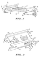
with reference to FIGS. 1-7. FIG. 1 is a perspective view of the card holding
apparatus according to the present invention, represented as a dual subscriber identity
module (SIM) card holder 10. The card holder 10 includes a first bracket structure
12, a second bracket structure 22, oriented parallel to and in opposition to the first
bracket structure 12 and a separation member 30 contiguously disposed between the
first bracket structure 12 and the second bracket structure 22. The separation member
30, together with the first bracket structure 12 and the second bracket structure 22
defines a first holding region 31 and a second holding region 32 that are in-line and
configured to slidingly engage a corresponding SIM card or suitable electronic
element.
The first bracket structure 12 is a c-shaped bracket including a top portion 13,
a bottom portion 14 and an intermediate portion 15 interconnecting the top portion 13
and the bottom portion 14. A first lever 36 is integrally formed along the intermediate
portion 15. The second bracket structure 22 is a c-shaped bracket including a top
portion 23, a bottom portion 24 and an intermediate portion 25 interconnecting the top
portion 23 and the bottom portion 24. A second lever 37 is integrally formed along
the intermediate portion 25. The separation member 30 is disposed between the
intermediate portion 15 of the first bracket structure 12 and the intermediate portion
25 of the second bracket structure 22. In this manner, the separation member 30 is
shared by the first holding region 31 and the second holding region 32.
The footprint of the first holding region 31 and the second holding region 32
are substantially similar to conventional SIM cards; therefore, in application, the card
holder 10 of the present invention is capable of holding multiple SIM cards, one over
the other, in a vertically stacked manner in an area having a footprint substantially the
same as that of a single SIM card, or other suitable electronic element. This is in
contrast to conventional card holders where the application of two or more cards
would take up at least twice the area of a single card holder. Therefore, the card
holder 10 of the present invention takes up less than half the surface area required to
accommodate conventional multi-card holding mechanisms.
Although the card holder 10 is described as including a pair of brackets
oriented in opposition to one another, various alternative configurations capable of
maintaining multiple cards or electronic elements in a substantially vertically stacked
manner such as, for example, the first and second brackets being offset from one
another are contemplated by the present invention and are within the spirit and scope
of the present disclosure. Further, the bracket structure 12, 22 is not construed to be
limited to c-shaped brackets, but can be any structure capable of maintaining a portion
of a SIM card or other suitable electronic device therein such as, but not limited to, I-brackets,
L-brackets or S-brackets.
Moreover, the card holder 10 of the present invention should not be limited to
a structure where the separation member 30 is shared by the holding regions 31, 32.
For example, a card holder having a structure where the separation member is not
shared by, but is placed or otherwise disposed between separate bracket structures is
contemplated by the present invention and is within the spirit and scope of the present
disclosure.
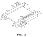
Referring to FIGS. 2-4, the separation member 30 has a central cavity (not
shown) configured to maintain electrical conductors 34 therein. The electrical
conductors 34 provide electrical signals to the SIM card or other suitable electronic
device maintained within the first holding region 31 through at least one opening 33
formed in the separation member 30. The electrical conductors 34 are coupled to
respective first and second contact members 40, 41 that extend from the card holder
10 and provide an electrical contact to corresponding electrical interconnections 53 of
a host, such as a printed circuit board 60 of a portable device. Additionally, the first
and second contact members 40, 41 provide a spring bias force against the card holder
10 when the card holder 10 is in operating position (e.g. engaged) relative to a host,
such that when the card holder 10 is disengaged from the host or a component on the
host, as described in greater detail below, the card holder 10 is slightly biased in an
upwards (e.g. away from the host) direction to promote easy removal of the SIM cards
or other suitable electronic devices from the card holder 10. FIG. 4 shows the first
and second contact members 40, 41 being external to the separation member 30, to
illustrate that the first and second contact members 40, 41 provide an electrical
contact between the SIM card 72 maintained within the first holding region 31 and the
electrical interconnectors 53. However, in application, the first and second contact
members 40, 41 are maintained substantially within the central cavity (not shown) of
the separation member 30, and extend from the card holder 10.
The bottom portion 14 of the first bracket structure 12, includes an attachment
member 38 at one end thereof configured to slidingly engage a corresponding
connection portion 57 of a base connector 50. The bottom portion 24 of the second
bracket structure 22 includes an attachment member 39 at one end thereof configured
to slidingly engage a corresponding connection portion 59 of the base connector 50.
The attachment members 38, 39 when engaged with the corresponding connection
portions 57, 59 of the base connector 50 form a pivot mechanism having an axis of
rotation represented by line A-A (FIG. 5), which provides for the card holder 10 being
rotationally positioned between an engaged (e.g. operating) and disengaged (e.g. open
or non-operating) position relative to a base 52 that is located on the printed circuit
board 60. At the end opposite attachment member 38, a first tab member 121 extends
from the bottom portion 14 of the first bracket structure 12. At the end opposite
attachment member 39, a second tab member 122 extends from the bottom portion 24
of the second bracket structure 22. An electrical contact 123 is configured as a switch
and connected to the bottom portion 14 of the card holder. As a switch, the electrical
contact 123 detects that a card has been inserted in one half of the card holder, such as
holding region 32. When the switch detects that a card is present, software operations
or other card dependent operations can be activated (or deactivated when the card is
removed). Such a switch may be similar to those in use with single card holders.
FIG. 5 is a perspective top view of the card holder 10 in an open (e.g. non-operating)
position relative to a printed circuit board 60. The base 52 is located on the
printed circuit board 60, and is configured to maintain the SIM cards held within the
card holder 10. As illustrated, the base 52 includes a first holding portion 54 having a
lip 522 formed therein. The base 52 also includes a second holding portion 56 having
a lip 521 (FIG. 4) formed therein. The first and second holding portions 54, 56 each
have a corresponding height (h) sufficient enough to maintain the corresponding
edges of the SIM cards 70, 72 on the printed circuit board 60. Also shown is at least
one third contact member 55, which provides an electrical connection, for example, to
the SIM card 70 maintained within the second holding region 32.
Disengaging the card holder 10 from the base 52 is accomplished, for
example, by the user sliding the card holder 10 away from the first and second
holding portions 54-56 by exerting an appropriate amount of force on at least one of
the levers 36, 37 until the first and second tab portions 121, 122 are separated from
the corresponding lips 521, 522 of the base 52. Once separated from the lips 521,
522, the spring bias force from the first and second contact members 40, 41 causes the
card holder 10 to raise slightly away from the base 52, such that the SIM cards 70, 72
may be removed from the card holder 10. Correspondingly, if one of the first and
second holding regions 31, 32 is empty, a SIM card or other suitable electronic device
may be placed within the empty holding region when the card holder 10 is disengaged
from the base 52. As shown, a first SIM card 70 is located substantially within the
second holding region 32; whereas a second SIM card 72 is separated from the first
holding region 31 to illustrate the location of the electrical conductors 34 provided
within the separation member 30.
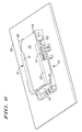
FIG. 6 is a perspective top view of the card holder 10 in operating (e.g.
engaged) position relative to the printed circuit board 60. As illustrated, at least one
of the SIM cards 72 is maintained within the base 52 so as to be in operating position
with respect to the device or component containing the printed circuit board 60. The
card holder 10 is placed in the operating position, for example, by the user providing a
downward force on the lever 37 until the card holder 10 is substantially parallel to the
printed circuit board 60 and then sliding the card holder 10 towards the base 52 until
the first and second tab portions 121, 122 of the card holder 10 are located
substantially underneath the corresponding lips 521, 522 of the first and second
holding portions 54, 56 of the base 52. The spring bias force provided by the first and
second contact members 40, 41 causes the first and second tab portions 121, 122 to
press against the lips 521, 522 of the base 52; thereby, latching the card holder 10 in
operating position relative to the base 52 and the printed circuit board 60.
By using the card holder 10 of the present invention, multiple smart cards can
be positioned relative to a printed circuit board 60 in a vertically stacked manner
within a substantially similar footprint to that of a single smart card. Thus, increased
functionality can be provided within a corresponding device while taking up
substantially the same amount of area as a single smart card. Thus, the additional real
estate provided on the printed circuit board 60 by not having multiple smart cards
located side-by-side on the same plane, provides for the ability to increase
functionality of the underlying device.
The exemplary card holder 10 is made of a two piece construction where the
central cavity is formed when the two pieces are combined. The electrical conductors
34 and the first and second contact members 40, 41 are positioned within an area of at
least one of the two pieces before the pieces are combined (e.g. glued, heat treated, or
other suitable manufacturing process) to form the card holder 10. Alternately, the
card holder 10 may be formed from a single piece of molded material. Such alternate,
and analogous constructions, will be readily understood by one of ordinary skill in the
art and such constructions are contemplated by the present disclosure and are within
the spirit and scope of the present invention. Although the present invention has been
described with reference to a card holder rotationally engaging a base structure, one of
ordinary skill in the art will recognize and appreciate that the card holder of the
present invention can be connected to the base structure or appropriate electrical
connections or connectors in a snap-fit fashion or other manner as suitable for the
particular application. Such alternate connection mechanisms and schemes are
contemplated by the present disclosure and are within the spirit and scope of the
present invention.
Additionally, although described as having the base connector 50 located
along a first bottom edge of the card holder 10, one of ordinary skill in the art will
recognize and appreciate that a suitable base connector can be located substantially
along the length of either the first bracket structure 12 or the second bracket structure
22 of the card holder 10, thereby providing for rotation along the length of the card
holder. Such an alternate embodiment, and those analogous thereto are contemplated
by the present disclosure, and thus are within the spirit and scope of the present
invention.
FIG. 7 is a schematic block diagram of a mobile communication device 100
incorporating the card holder 10 of the present invention. The mobile communication
device 100 can be embodied as any device, such as portable electronic devices,
cellular telephones, pagers, palm top computers, lap top computers, or the like that
require an electronic card, such as SIM card 72, a smart card, memory card or the like,
or a combination of such cards. The card holder 10 is particularly advantageous in a
cellular telephone because cellular telephones are very compact communication
devices wherein it is desirable to accommodate more than one card to enable
maximum flexibility in the smallest possible volume for a very compact form factor.
The mobile communication device 100 includes the card holder 10, a device
controller 102, a memory 104, an input/output (I/O) controller 106, and a transceiver
108. The mobile communication device 100 may include a display controller 110
which is operable to control the formatting and display of data on a suitable display
(not shown) based on display control signals 109 provided by the device controller
102. Each of the aforementioned components is illustrated as being maintained (e.g.
carried) on a single printed circuit board 60 that is carried within a device housing
(not shown). However, it will be appreciated by those of ordinary skill in the art that
the components may be maintained on several printed circuit boards or other suitable
mechanisms.
The device controller 102, represented as a processor, is operable to control
the operation of the mobile communication device 100. The device controller 102
may be may be implemented in any suitable structure such as, but not limited to, a
single processor, a plurality of processors, a digital signal processor, a dedicated piece
of hardware (e.g. ASIC), discrete logic circuitry, state machine or any device that
manipulates signals based on operational instructions or software executing on one or
more processing devices. The operational instructions or software and any
corresponding data related thereto would be stored in the memory 104, which may
include a single memory device or a plurality of memory devices. Such a memory
device may include any element that stores digital data including, but not limited to,
RAM, ROM, CD-ROM and/or any storage medium that stores digital information.
Transmission or receiving information 105, for example, a cellular number to
be dialed or the acceptance of an incoming call from a wireless network is provided to
the device controller 102 by the I/O controller 106. The cellular number may be
provided, for example, by a user depressing numerical or other suitable keys on a
keypad (not shown) which, in turn, provide electrical signals corresponding to the
particular number to the device controller 102. Voice and/or image data 107 that is to
be transmitted by the mobile communication device 100 is provided to the transceiver
108 by the device controller 102. Voice and/or image data 107 that is to be received
by the mobile communication device 100 is provided to the device controller 102 by
the transceiver 108. The operation of the I/O controller 106, transceiver 108 and
display controller 110 are well known by those of ordinary skill in the art and will not
be further discussed herein as not to obscure the disclosure or deviate from the
description of the present invention.
The card holder 10 of the present invention is illustrated as being in operating
(e.g. engaged) position with respect to the printed circuit board 60, such that one SIM
card 72 or two card devices can communicate with the device controller 102. For
example, the encryption algorithms, mobile network user identification data or other
suitable information maintained within the SIM card 72 may be transferred between
the device controller 102 and the SIM card 72 via the electrical interconnectors 53 of
the printed circuit board 60. In application, the algorithms and other information
stored within the SIM card 72 may be transmitted to the electrical interconnectors 53
via the electrical conductors 34 and at least one of the contact members 40,41 (FIG. 3)
of the card holder 10. When the card holder 10 is in non-operating (e.g. disengaged)
position relative to the printed circuit board 60, the interconnection between the SIM
card 72 and the device controller 102 is broken as the first and second contact
members 40,41 (FIG. 3) are disconnected from the electrical interconnectors 53;
thereby, preventing the SIM card 72 or other suitable electronic element from
communicating with the device controller 102.
The above detailed description of the invention and the examples described
therein have been presented for the purposes of illustration and description. It is
therefore contemplated that the present invention cover any and all modifications,
variations or equivalents that fall within the spirit and scope of the basic underlying
principles disclosed above and claimed herein.