US7354290B2 - Surface contact card holder - Google Patents
Surface contact card holder Download PDFInfo
- Publication number
- US7354290B2 US7354290B2 US11/616,826 US61682606A US7354290B2 US 7354290 B2 US7354290 B2 US 7354290B2 US 61682606 A US61682606 A US 61682606A US 7354290 B2 US7354290 B2 US 7354290B2
- Authority
- US
- United States
- Prior art keywords
- surface contact
- contact card
- holding
- elastic member
- card holder
- Prior art date
- Legal status (The legal status is an assumption and is not a legal conclusion. Google has not performed a legal analysis and makes no representation as to the accuracy of the status listed.)
- Expired - Fee Related
Links
Images


Classifications
-
- H—ELECTRICITY
- H01—ELECTRIC ELEMENTS
- H01R—ELECTRICALLY-CONDUCTIVE CONNECTIONS; STRUCTURAL ASSOCIATIONS OF A PLURALITY OF MUTUALLY-INSULATED ELECTRICAL CONNECTING ELEMENTS; COUPLING DEVICES; CURRENT COLLECTORS
- H01R13/00—Details of coupling devices of the kinds covered by groups H01R12/70 or H01R24/00 - H01R33/00
- H01R13/02—Contact members
- H01R13/22—Contacts for co-operating by abutting
- H01R13/24—Contacts for co-operating by abutting resilient; resiliently-mounted
- H01R13/2464—Contacts for co-operating by abutting resilient; resiliently-mounted characterized by the contact point
- H01R13/2478—Contacts for co-operating by abutting resilient; resiliently-mounted characterized by the contact point spherical
-
- H—ELECTRICITY
- H01—ELECTRIC ELEMENTS
- H01R—ELECTRICALLY-CONDUCTIVE CONNECTIONS; STRUCTURAL ASSOCIATIONS OF A PLURALITY OF MUTUALLY-INSULATED ELECTRICAL CONNECTING ELEMENTS; COUPLING DEVICES; CURRENT COLLECTORS
- H01R12/00—Structural associations of a plurality of mutually-insulated electrical connecting elements, specially adapted for printed circuits, e.g. printed circuit boards [PCB], flat or ribbon cables, or like generally planar structures, e.g. terminal strips, terminal blocks; Coupling devices specially adapted for printed circuits, flat or ribbon cables, or like generally planar structures; Terminals specially adapted for contact with, or insertion into, printed circuits, flat or ribbon cables, or like generally planar structures
- H01R12/70—Coupling devices
- H01R12/7005—Guiding, mounting, polarizing or locking means; Extractors
- H01R12/7011—Locking or fixing a connector to a PCB
- H01R12/7017—Snap means
- H01R12/7029—Snap means not integral with the coupling device
-
- H—ELECTRICITY
- H01—ELECTRIC ELEMENTS
- H01R—ELECTRICALLY-CONDUCTIVE CONNECTIONS; STRUCTURAL ASSOCIATIONS OF A PLURALITY OF MUTUALLY-INSULATED ELECTRICAL CONNECTING ELEMENTS; COUPLING DEVICES; CURRENT COLLECTORS
- H01R12/00—Structural associations of a plurality of mutually-insulated electrical connecting elements, specially adapted for printed circuits, e.g. printed circuit boards [PCB], flat or ribbon cables, or like generally planar structures, e.g. terminal strips, terminal blocks; Coupling devices specially adapted for printed circuits, flat or ribbon cables, or like generally planar structures; Terminals specially adapted for contact with, or insertion into, printed circuits, flat or ribbon cables, or like generally planar structures
- H01R12/70—Coupling devices
- H01R12/71—Coupling devices for rigid printing circuits or like structures
- H01R12/712—Coupling devices for rigid printing circuits or like structures co-operating with the surface of the printed circuit or with a coupling device exclusively provided on the surface of the printed circuit
- H01R12/714—Coupling devices for rigid printing circuits or like structures co-operating with the surface of the printed circuit or with a coupling device exclusively provided on the surface of the printed circuit with contacts abutting directly the printed circuit; Button contacts therefore provided on the printed circuit
-
- H—ELECTRICITY
- H01—ELECTRIC ELEMENTS
- H01R—ELECTRICALLY-CONDUCTIVE CONNECTIONS; STRUCTURAL ASSOCIATIONS OF A PLURALITY OF MUTUALLY-INSULATED ELECTRICAL CONNECTING ELEMENTS; COUPLING DEVICES; CURRENT COLLECTORS
- H01R2201/00—Connectors or connections adapted for particular applications
- H01R2201/16—Connectors or connections adapted for particular applications for telephony
-
- Y—GENERAL TAGGING OF NEW TECHNOLOGICAL DEVELOPMENTS; GENERAL TAGGING OF CROSS-SECTIONAL TECHNOLOGIES SPANNING OVER SEVERAL SECTIONS OF THE IPC; TECHNICAL SUBJECTS COVERED BY FORMER USPC CROSS-REFERENCE ART COLLECTIONS [XRACs] AND DIGESTS
- Y10—TECHNICAL SUBJECTS COVERED BY FORMER USPC
- Y10S—TECHNICAL SUBJECTS COVERED BY FORMER USPC CROSS-REFERENCE ART COLLECTIONS [XRACs] AND DIGESTS
- Y10S439/00—Electrical connectors
- Y10S439/923—Separation or disconnection aid
Definitions
- the present invention generally relates to mechanisms for holding card members in electronic devices and, particularly, to a surface contact card holder configured (i.e., structured and arranged) for holding a surface contact card in a portable electronic device.
- SIM subscriber identity module
- a conventional mechanism for holding a SIM card therein includes a base 92 and a holding structure 94 .
- the base 92 defines a receiving recess 921 .
- a SIM connector 90 having a plurality of contacts is set in a middle of the receiving recess 921 .
- the shape and size of the receiving recess 921 are the same as those of the SIM card.
- the holding structure 94 is located adjacent to one end of the receiving recess 921 and can be moved back and forth along a direction as indicated by the arrow shown in FIG. 6 .
- the holding structure 94 is moved away from the receiving recess 921 and the SIM card is inserted into the receiving recess 921 . Then, the holding structure 94 is moved adjacent to the receiving recess 921 so as to latch the SIM card in the receiving recess 921 . In the same way, the SIM card can be released by moving the holding structure 94 away from the receiving recess 921 .
- the holding structure 94 can be easily moved so that it is convenient for a user to operate.
- shock can easily force the holding structure 94 to move off the receiving recess 921 .
- the SIM card will not connect well with the SIM contactor 90 and may even be released from the receiving recess 921 .
- such a conventional mechanism cannot hold the SIM card steadily in the receiving recess 921 .
- a surface contact card holder in one embodiment thereof, includes a body and a receiving mechanism.
- the receiving mechanism has two sidewalls, an elastic member, a holding wall, and a holding piece.
- the sidewalls, the elastic member, and the holding wall are provided on the body.
- the holding piece is formed on one of the elastic member and the holding wall.
- the elastic member and the holding wall cooperate to hold a surface contact card in a first direction.
- the two sidewalls cooperate to hold the surface contact card in a second direction.
- the holding piece and the body cooperate to hold the surface contact card in a third direction.
- the elastic member can be pressed in the first direction.
- FIG. 1 is an isometric view of a surface contact card holder in accordance with a preferred embodiment
- FIG. 2 is an isometric view of a connector used with the surface contact card holder in FIG. 1 ;
- FIG. 3 is an isometric, assembled view of the surface contact card holder and the connector
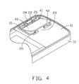
- FIG. 4 is an isometric view of the surface contact card holder, the connector, and a surface contact card, showing the surface contact card in a first position;
- FIG. 5 is similar to FIG. 4 but showing the surface contact card in a second position
- FIG. 6 is an isometric view of a conventional SIM card holder.
- the present surface contact card holder can be used for holding surface contact cards such as SIM cards, compact flash cards (CFs), multimedia cards (MMCs), and so on.
- FIGS. 1 and 4 - 5 show a surface contact card holder 8 for holding a SIM card 40 therein.
- the SIM card 40 has a first end 41 and a second end 42 .
- the first end 41 is opposed to the second end 42 .
- the surface contact card holder 8 includes a body 10 and a receiving mechanism 20 .
- the body 10 is a substantially rectangular board in shape and has a body surface 11 at one side thereof.
- the receiving mechanism 20 is provided at the body surface 11 of the body 10 .
- the receiving mechanism 20 is configured for receiving the SIM card 40 therein.
- the receiving mechanism 20 includes a pair of sidewalls 21 and a positioning wall 22 .
- Each of the sidewall 21 is a substantially U-shaped strip in shape, and has a first arm 26 and a second arm 27 directly formed at two opposite ends of the sidewall 21 and extending toward the other sidewall 21 .
- the first arms 26 are made of an elastic material.
- the two sidewalls 21 are symmetrically arranged with each other about a line.
- the positioning wall 22 is a substantially strip in shape and is located between the two first arms 26 .
- the positioning wall 22 is substantially parallel to the second arms 27 . Two adjacent ends of the second arms 27 together define an opening 23 therebetween.
- each first arm 26 is bent towards the second arm 27 .
- a holding piece 25 extends perpendicularly from the second arm 27 of each sidewall 21 and towards the positioning wall 22 .
- Each holding piece 25 is a substantially rectangular board in shape.
- a positioning piece 24 extends perpendicularly from the positioning wall 22 and towards the second arm 27 .
- the two sidewalls 21 , the two holding pieces 25 , the positioning wall 22 , the positioning piece 24 , and the body 10 cooperate to define a receiving groove 28 .
- the receiving groove 28 is a receiving space surrounded by the side walls 21 and the positioning piece 24 and configured for receiving the SIM card 40 therein.
- the positioning piece 24 is made of an elastic material.
- a SIM connector 30 having a plurality of contacts 32 is provided in the body 10 .
- Each contact 32 includes a top contact 321 and a bottom contact 322 .
- the top contact 321 and the bottom contact 322 of each contact 32 are electrically connected to each other.
- the body 10 defines a through hole 12 therethrough.
- the hole 12 communicates with the receiving groove 28 .
- the SIM connector 30 is configured for receipt in the through hole 12 allowing the top contacts 321 to be exposed out of the body surface 11 .
- the SIM card 40 is electronically connected with the top contacts 321 of the SIM connector 30 .
- the bottom contacts 322 are electronically connected with a processor (not shown) in the body 10 so that the SIM connector 30 transfers the information in the SIM card 40 to the processor.
- the first end 41 of the SIM card 40 is inserted between the positioning piece 24 and the body surface 11 of the body 10 .
- the SIM card 40 is located in a first position.
- the SIM card 40 is pushed towards the positioning wall 22 .
- the first arms 26 are pressed to move away from the second arms 27 and a force is collected.
- the second end 42 of the SIM card 40 slides relative to the holding pieces 25 . After the second end 42 slides over the holding pieces 25 , the SIM card 40 is pressed downwardly towards the body surface 11 .
- the SIM card 40 is pushed to abut with the second arms 27 due to the force produced by the first arms 26 and the first arms 26 go back to their original position.
- the SIM card 40 is mounted into the receiving groove 28 of the body 10 , as shown in FIG. 5 .
- the SIM card 40 is located in a second position.
- the first arms 26 can be slightly pressed by the SIM card 40 and the second arms 27 .
- the first arms 26 and the second arms 27 cooperate to hold the SIM card 40 in a first direction parallel to the SIM card 40 .
- the two sidewalls 21 cooperate to hold the SIM card 40 in a second direction parallel to the SIM card 40 and perpendicular to the first direction.
- the positioning piece 24 , the holding pieces 25 , and the body 10 cooperate to hold the SIM card 40 in a third direction perpendicular to the SIM card 40 .
- the first, second, and third directions are perpendicular to each other.
- the SIM card 40 is pushed toward the positioning wall 22 by pushing the second end 42 through the opening 23 .
- the first arms 26 are pressed to move away from the second arms 27 and the force is collected.
- the second end 42 of the SIM card 40 slides relative to the holding pieces 25 . After the second end 42 slides over the holding pieces 25 , the SIM card 40 can be upwardly removed.
- first arms 26 may be directly formed on the body 11 and be separate from the sidewalls 21 .
- first arms 26 may be directly formed on the positioning wall 22 .
- the first arms 26 may be another type of elastic member such as a spring. The spring may be mounted to the positioning wall 22 and can cooperate with the second arms 27 to hold the SIM card 40 in the first direction.
- the second arms 27 may be another holding wall directly formed on the body 11 and be separate from the sidewalls 21 .
Abstract
Description
Claims (13)
Applications Claiming Priority (2)
| Application Number | Priority Date | Filing Date | Title |
|---|---|---|---|
| CN200610034655.6 | 2006-03-23 | ||
| CNB2006100346556A CN100553418C (en) | 2006-03-23 | 2006-03-23 | Chip card holding mechanism |
Publications (2)
| Publication Number | Publication Date |
|---|---|
| US20070224871A1 US20070224871A1 (en) | 2007-09-27 |
| US7354290B2 true US7354290B2 (en) | 2008-04-08 |
Family
ID=38534068
Family Applications (1)
| Application Number | Title | Priority Date | Filing Date |
|---|---|---|---|
| US11/616,826 Expired - Fee Related US7354290B2 (en) | 2006-03-23 | 2006-12-27 | Surface contact card holder |
Country Status (2)
| Country | Link |
|---|---|
| US (1) | US7354290B2 (en) |
| CN (1) | CN100553418C (en) |
Cited By (8)
| Publication number | Priority date | Publication date | Assignee | Title |
|---|---|---|---|---|
| US20070097663A1 (en) * | 2005-11-02 | 2007-05-03 | Partick Wallace | Card holder arrangement for circuit assembly |
| US20100053917A1 (en) * | 2008-08-28 | 2010-03-04 | Chi Mei Communication Systems, Inc. | Chip card holder |
| US20100084310A1 (en) * | 2008-10-08 | 2010-04-08 | Fih (Hong Kong) Limited | Chip card holder |
| US7988454B1 (en) * | 2010-03-30 | 2011-08-02 | Fu Tai Hua Industry (Shenzhen) Co., Ltd. | Card connector assembly for portable electronic device |
| US20130335896A1 (en) * | 2012-06-19 | 2013-12-19 | Fih (Hong Kong) Limited | Chip card holder with protective cover for portable electronic devices |
| US20140038445A1 (en) * | 2012-08-06 | 2014-02-06 | Fih (Hong Kong) Limited | Chip card holder for electronic device |
| US20150011129A1 (en) * | 2012-04-20 | 2015-01-08 | Huawei Device Co., Ltd. | Foolproof Structure for Sharing Card Slot Space |
| US11123929B2 (en) * | 2016-05-12 | 2021-09-21 | Hewlett-Packard Development Company, L.P. | Data units for build material identification in additive manufacturing |
Families Citing this family (6)
| Publication number | Priority date | Publication date | Assignee | Title |
|---|---|---|---|---|
| US20080200057A1 (en) * | 2007-02-20 | 2008-08-21 | Geng Yu Ming | Half length SIM card reader with cover and hinge |
| CN101615661B (en) * | 2008-06-26 | 2012-07-04 | 深圳富泰宏精密工业有限公司 | Clamping structure of battery cover |
| CN101677163A (en) * | 2008-09-18 | 2010-03-24 | 深圳富泰宏精密工业有限公司 | Holding structure for SIM card |
| CN101685932B (en) * | 2008-09-26 | 2012-07-25 | 深圳富泰宏精密工业有限公司 | Chip card fixedly holding structure |
| KR101875903B1 (en) * | 2015-12-11 | 2018-08-03 | 몰렉스 엘엘씨 | Card tray for electronic device |
| WO2018129826A1 (en) * | 2017-01-16 | 2018-07-19 | 华为技术有限公司 | Apparatus for fixing printed circuit board and electronic device |
Citations (1)
| Publication number | Priority date | Publication date | Assignee | Title |
|---|---|---|---|---|
| US6193557B1 (en) * | 1999-04-01 | 2001-02-27 | Rocco Luvini | Chip card connector |
-
2006
- 2006-03-23 CN CNB2006100346556A patent/CN100553418C/en not_active Expired - Fee Related
- 2006-12-27 US US11/616,826 patent/US7354290B2/en not_active Expired - Fee Related
Patent Citations (1)
| Publication number | Priority date | Publication date | Assignee | Title |
|---|---|---|---|---|
| US6193557B1 (en) * | 1999-04-01 | 2001-02-27 | Rocco Luvini | Chip card connector |
Cited By (12)
| Publication number | Priority date | Publication date | Assignee | Title |
|---|---|---|---|---|
| US20070097663A1 (en) * | 2005-11-02 | 2007-05-03 | Partick Wallace | Card holder arrangement for circuit assembly |
| US7623357B2 (en) * | 2005-11-02 | 2009-11-24 | Symbol Technologies, Inc. | Card holder arrangement for circuit assembly |
| US20100053917A1 (en) * | 2008-08-28 | 2010-03-04 | Chi Mei Communication Systems, Inc. | Chip card holder |
| US8059419B2 (en) * | 2008-08-28 | 2011-11-15 | Chi Mei Communication Systems, Inc. | Chip card holder |
| US20100084310A1 (en) * | 2008-10-08 | 2010-04-08 | Fih (Hong Kong) Limited | Chip card holder |
| US7988454B1 (en) * | 2010-03-30 | 2011-08-02 | Fu Tai Hua Industry (Shenzhen) Co., Ltd. | Card connector assembly for portable electronic device |
| US20150011129A1 (en) * | 2012-04-20 | 2015-01-08 | Huawei Device Co., Ltd. | Foolproof Structure for Sharing Card Slot Space |
| US9219320B2 (en) * | 2012-04-20 | 2015-12-22 | Huawei Device Co., Ltd. | Foolproof structure for sharing card slot space |
| US20130335896A1 (en) * | 2012-06-19 | 2013-12-19 | Fih (Hong Kong) Limited | Chip card holder with protective cover for portable electronic devices |
| US20140038445A1 (en) * | 2012-08-06 | 2014-02-06 | Fih (Hong Kong) Limited | Chip card holder for electronic device |
| US8968030B2 (en) * | 2012-08-06 | 2015-03-03 | Zhongshan Innocloud Intellectual Property Services Co., Ltd. | Chip card holder for electronic device |
| US11123929B2 (en) * | 2016-05-12 | 2021-09-21 | Hewlett-Packard Development Company, L.P. | Data units for build material identification in additive manufacturing |
Also Published As
| Publication number | Publication date |
|---|---|
| US20070224871A1 (en) | 2007-09-27 |
| CN101043798A (en) | 2007-09-26 |
| CN100553418C (en) | 2009-10-21 |
Similar Documents
| Publication | Publication Date | Title |
|---|---|---|
| US7354290B2 (en) | Surface contact card holder | |
| US7583514B2 (en) | SIM card holder | |
| US7445510B2 (en) | Surface contact card holder | |
| US7344401B2 (en) | Surface contact card holder | |
| US7682178B2 (en) | Surface contact card holder | |
| US8976521B2 (en) | Surface contact card holder for electronic device | |
| US7303414B2 (en) | Surface contact card holder | |
| US7244135B2 (en) | Surface contact card latching assembly | |
| US7255605B2 (en) | Surface contact card holder | |
| US7059909B1 (en) | Electrical card connector with improved contact structure | |
| US7780464B2 (en) | Surface contact card holder and portable electronic device using the same | |
| US20140154926A1 (en) | Electronic card connector and electronic device using the same | |
| US20070060198A1 (en) | Structure for housing a SIM card and a flash memory card | |
| US7407414B2 (en) | Surface contact card holder | |
| US7494360B2 (en) | Surface contact card holder | |
| US8968030B2 (en) | Chip card holder for electronic device | |
| JP2010129173A (en) | Card connector | |
| US7699659B2 (en) | Surface contact card latching assembly | |
| US7252527B2 (en) | Surface contact card holder | |
| US7372136B2 (en) | Chip card retaining mechanism | |
| US6761591B1 (en) | SIM card receiving mechanism | |
| JP2010129168A (en) | Card connector | |
| US7376230B2 (en) | Mobile phone and battery-release device | |
| JP3385249B2 (en) | Card connector structure | |
| US8077451B2 (en) | Surface contact card retention assembly |
Legal Events
| Date | Code | Title | Description |
|---|---|---|---|
| AS | Assignment |
Owner name: SHENZHEN FUTAIHONG PRECISION INDUSTRIAL CO,.LTD., Free format text: ASSIGNMENT OF ASSIGNORS INTEREST;ASSIGNORS:ZHAN, ZI-GANG;CHEN, CHIA-HUA;REEL/FRAME:018683/0767 Effective date: 20061221 Owner name: SUTECH TRADING LIMITED, VIRGIN ISLANDS, BRITISH Free format text: ASSIGNMENT OF ASSIGNORS INTEREST;ASSIGNORS:ZHAN, ZI-GANG;CHEN, CHIA-HUA;REEL/FRAME:018683/0767 Effective date: 20061221 |
|
| AS | Assignment |
Owner name: FIH (HONG KONG) LIMITED, HONG KONG Free format text: ASSIGNMENT OF ASSIGNORS INTEREST;ASSIGNOR:SUTECH TRADING LIMITED;REEL/FRAME:022597/0324 Effective date: 20090317 |
|
| FPAY | Fee payment |
Year of fee payment: 4 |
|
| REMI | Maintenance fee reminder mailed | ||
| LAPS | Lapse for failure to pay maintenance fees | ||
| STCH | Information on status: patent discontinuation |
Free format text: PATENT EXPIRED DUE TO NONPAYMENT OF MAINTENANCE FEES UNDER 37 CFR 1.362 |
|
| FP | Lapsed due to failure to pay maintenance fee |
Effective date: 20160408 |