EP1418422A1 - Mass spectrometer - Google Patents
Mass spectrometer Download PDFInfo
- Publication number
- EP1418422A1 EP1418422A1 EP20030024873 EP03024873A EP1418422A1 EP 1418422 A1 EP1418422 A1 EP 1418422A1 EP 20030024873 EP20030024873 EP 20030024873 EP 03024873 A EP03024873 A EP 03024873A EP 1418422 A1 EP1418422 A1 EP 1418422A1
- Authority
- EP
- European Patent Office
- Prior art keywords
- gas
- sample
- flow rate
- mass spectrometer
- fuel cell
- Prior art date
- Legal status (The legal status is an assumption and is not a legal conclusion. Google has not performed a legal analysis and makes no representation as to the accuracy of the status listed.)
- Withdrawn
Links
Images




Classifications
-
- H—ELECTRICITY
- H01—ELECTRIC ELEMENTS
- H01J—ELECTRIC DISCHARGE TUBES OR DISCHARGE LAMPS
- H01J49/00—Particle spectrometers or separator tubes
- H01J49/02—Details
- H01J49/04—Arrangements for introducing or extracting samples to be analysed, e.g. vacuum locks; Arrangements for external adjustment of electron- or ion-optical components
-
- H—ELECTRICITY
- H01—ELECTRIC ELEMENTS
- H01M—PROCESSES OR MEANS, e.g. BATTERIES, FOR THE DIRECT CONVERSION OF CHEMICAL ENERGY INTO ELECTRICAL ENERGY
- H01M8/00—Fuel cells; Manufacture thereof
- H01M8/04—Auxiliary arrangements, e.g. for control of pressure or for circulation of fluids
- H01M8/04082—Arrangements for control of reactant parameters, e.g. pressure or concentration
-
- G—PHYSICS
- G01—MEASURING; TESTING
- G01N—INVESTIGATING OR ANALYSING MATERIALS BY DETERMINING THEIR CHEMICAL OR PHYSICAL PROPERTIES
- G01N33/00—Investigating or analysing materials by specific methods not covered by groups G01N1/00 - G01N31/00
- G01N33/0004—Gaseous mixtures, e.g. polluted air
- G01N33/0009—General constructional details of gas analysers, e.g. portable test equipment
- G01N33/0027—General constructional details of gas analysers, e.g. portable test equipment concerning the detector
- G01N33/0036—General constructional details of gas analysers, e.g. portable test equipment concerning the detector specially adapted to detect a particular component
- G01N33/005—H2
-
- Y—GENERAL TAGGING OF NEW TECHNOLOGICAL DEVELOPMENTS; GENERAL TAGGING OF CROSS-SECTIONAL TECHNOLOGIES SPANNING OVER SEVERAL SECTIONS OF THE IPC; TECHNICAL SUBJECTS COVERED BY FORMER USPC CROSS-REFERENCE ART COLLECTIONS [XRACs] AND DIGESTS
- Y02—TECHNOLOGIES OR APPLICATIONS FOR MITIGATION OR ADAPTATION AGAINST CLIMATE CHANGE
- Y02E—REDUCTION OF GREENHOUSE GAS [GHG] EMISSIONS, RELATED TO ENERGY GENERATION, TRANSMISSION OR DISTRIBUTION
- Y02E60/00—Enabling technologies; Technologies with a potential or indirect contribution to GHG emissions mitigation
- Y02E60/30—Hydrogen technology
- Y02E60/50—Fuel cells
Definitions
- the present invention relates to a mass spectrometer which detects impurity in sample gas of a low flow rate in a high sensitivity by atmospheric pressure chemical ionization.
- An APCI-MS (Atmospheric Pressure Chemical Ionization Mass Spectrometer) is a device which selectively ionizes traces of components to be contained in a sample by taking advantage of an ion molecular reaction to detect in a high sensitivity, and has been used for biotechnology such as protein analysis and for impurity analysis in a semiconductor process.
- a primary ionization part is separated from a sample inlet part, whereby clean gas is introduced into the primary ionization part to generate a primary ion; sample gas introduced into the sample inlet part is mixed with the primary ion generated in the primary ionization part to ionize an object substance to be contained in the sample gas by an ion-molecule reaction (See Japanese Patent Application Laid-Open No. 6-310091).
- the sensitivity is generally on the order of 0.1%, and a sampling flow rate.of about (3 to 4) L/min (liter/minute) is required.
- a flow rate of each of hydrogen and air necessary for an operation of the fuel cell is generally about 1 L/min, and when a sampling flow rate during an online analysis is high, a flow rate of hydrogen and air during an ordinary operation becomes different from that of hydrogen and air during an online analysis. In other words, there is a problem that it becomes difficult to accurately evaluate performance of an operation system of the fuel cell and the fuel cell.
- a substance targeted for measurement on the order of ppm in the sample is measured with as low a sampling flow rate as about 0.1 L/min.
- a counter electrode having a hole through which the primary ions are caused to pass through toward the secondary ionization part.
- the secondary ionization part is maintained at negative pressure as compared with the primary ionization part.
- the ions generated in the secondary ionization part is introduced into a mass spectrometric part which has been evacuated in a high vacuum, through an aperture, and mass spectrometric analysis is performed by a mass spectrometer such as a quadrupole type mass spectrometer, an ion trap type mass spectrometer, an ion trap-TOF type (time of flight type) mass spectrometer and a magnetic field type mass spectrometer.
- a mass spectrometer such as a quadrupole type mass spectrometer, an ion trap type mass spectrometer, an ion trap-TOF type (time of flight type) mass spectrometer and a magnetic field type mass spectrometer.
- a sample introduced from a target of inspection is mixed with dilution gas in a mixing portion, and is introduced into the secondary ionization part at a substantially constant flow rate (1 L/min).
- Flow rates of dilution gas and the sample which are to flow into the mixing portion are controlled by flow rate control means respectively.
- a flow rate of the dilution gas for flowing through the mixing portion is to be set higher than that of the sample for flowing through the mixing portion. For example, assuming that a flow rate of dilution gas for flowing through the mixing portion is 0.9 L/min or higher, a flow rate of the sample for flowing through the mixing portion is 0.1 L/min or lower, and that of gas mixed in the mixing portion is about 1 L/min, these will be introduced into the secondary ionization part.
- the flow rate of the sample to be introduced from the target of inspection is reduced, whereby an influence on the target of inspection by the sampling can be reduced.
- an outlet flow rate of the reagent gas to the secondary ionization part is set within a range of (0.1 to 0.3) L/min, a suitable sensitivity can be obtained.
- dilution gas there will be selected dilution gas which does not interfere with ionization of a substance targeted for measurement in the sample.
- dilution gas ionization potential of which is the same as or higher than ionization potential of the substance targeted for measurement, or dilution gas, proton affinity of which is the same as or lower than that of the substance targeted for measurement is used, whereby an influence of lowered concentration of the substance targeted for measurement due to mixing of the dilution gas can be mitigated even at low sampling flow rate without interfering with the ionization of the substance targeted for measurement.
- the sample is collected from an inlet piping for introducing gas or liquid to the fuel cell or an outlet piping for discharging-gas or liquid from the fuel cell.
- a sample inlet of the secondary ionization part and the above-described inlet piping or outlet piping are connected together through a sample inlet piping through which the sample collected is to flow.
- a dilution gas piping through which the dilution gas flows.
- flow rate control means for controlling the flow rate of the dilution gas
- sample inlet piping there is arranged flow rate control means for controlling the flow rate of the sample collected.
- sample gas is collected, traces of hydrogen in the sample gas is selectively ionized through the use of any of argon, helium and nitrogen as the dilution gas, and through the use of the atmospheric pressure chemical two-step ionization , source, and traces of hydrogen can be measured in a high sensitivity online in real time.
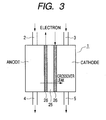
- Fig. 3 is a view for explaining structure of a polymer electrolyte fuel cell to which the present invention is applied.
- PEFC polymer electrolyte fuel cell 1
- the development has been pursued as an automotive and dispersal power source or as a fuel cell for a household.
- hydrogen gas is introduced as fuel from a gas inlet piping 2 on anode of the fuel cell, is discharged from a gas outlet piping 4 on anode, air is introduced from a gas inlet piping 3 on cathode, and is discharged from a gas outlet piping 5 on cathode.
- a hydrogen molecule is dissociated by a hydrogen atom on anode, further emits electrons, proton (H + ) generated moves from an electrode 26 on anode to an electrode 26 on cathode, and reacts with an oxygen molecule in air to form water. At this time, an electric current flows between the electrode 26 on anode and the electrode 26 on cathode.
- crossover leak is a phenomenon in which a hydrogen molecule introduced to the anode side moves within the membrane 25 toward the cathode side, for leaking on the cathode side in a state of hydrogen molecule instead of converting to proton by a catalytic action of a polymer electrolyte membrane 25, and permeating the interior of the membrane
- the hydrogen molecule that has leaked on the cathode side reacts vigorously with oxygen molecules in air on the cathode side of the membrane 25 to deteriorate the polymer electrolyte membrane 25 for increasing the amount of crossover leak more and more. Gradually, the electric power decreases and the fuel cell becomes unable to sufficiently perform.
- the concentration (amount of crossover leak) of the hydrogen molecule that has leaked on the cathode side can be determined by measuring concentration of trace hydrogen in the gas for flowing through the gas outlet piping 5 on cathode. This amount of crossover leak is on several ppm level at least. For a device for evaluating online an operating performance in a state in which the fuel cell has been actuated, highly sensitive detectability on the order of ppm is required as described previously.
- DMFC Direct Methanol Fuel Cell
- inactive gas such as nitrogen and rare gas
- trace methanol to be contained in gas that flows through the gas outlet piping 5 on cathode that has leaked on the cathode side.
- the methanol that has permeated the membrane 25 is changed into CO 2 by the catalytic action of the membrane 25 on the cathode side, and therefore, there is measured trace CO 2 on the order of ppm to be contained in gas that flows through the gas outlet piping 5 on cathode.
- Fig. 1 shows an example of the present invention, and is a view explaining structure in which outlet gas of a fuel cell is analyzed online through the use of a mass spectrometer.
- a gas inlet piping 2 on anode for introducing hydrogen gas there are connected together a gas outlet piping 4 on anode for discharging hydrogen gas that has not been consumed, a gas inlet piping 3 on cathode for introducing air, and a gas outlet piping 5 on cathode for discharging air.
- a sample gas inlet piping 7 To a branch 6 of the gas outlet piping 5 on cathode, there is connected a sample gas inlet piping 7, and the sample gas inlet piping 7 is connected to a mass spectrometer 8.
- a dilution gas piping 9 in which a mass flow controller 14 has been arranged is connected to the sample gas inlet piping 7.
- the mass spectrometer 8 is composed of an ion source 10 and a mass spectrometric part 11 evacuated in a high vacuum.
- a portion or the whole quantity of gas exhausted into the gas outlet piping 5 on cathode of the fuel cell 1 is sampled in order to measure a crossover leak of hydrogen.
- the gas thus sampled is (1) introduced into the mass spectrometer 8 as it is as sample gas, or (2) is mixed with dilution gas to be introduced into the sample gas inlet piping 7 from the dilution gas piping 9, and is introduced into the mass spectrometer as sample gas containing hydrogen as substance targeted for measurement.
- the sample gas is introduced into the ion source 10 by a pump 13. At this time, in order to stabilize the sensitivity of the mass spectrometer, it is important to make an amount of inlet of the sample gas into the ion source 10 constant.
- the flow rate of the sample gas is controlled by a mass flow controller to be arranged in any of the following (1), (2) and (3).
- a mass flow controller 12-1 to be arranged in a sample gas inlet piping (in Fig. 1, piping indicated by 7, in Fig. 2, piping indicated by 31 through which the branch 6 of Fig. 1 is connected to the dilution gas inlet 16) between the branch 6 and a mixing portion 33 (will be described later).
- a mass flow controller 12-2 to be arranged in a mixed gas inlet piping (in Fig. 1, piping indicated by 7, in Fig. 2, piping indicated by 31 through which the branch 6 of Fig.
- the mass flow controller 12-2 is, as shown in Fig. 2, arranged in the sample gas inlet piping between the mixing portion 33 and the dilution gas inlet 16.
- the mass flow controller 12-3 is, as shown in Fig. 2, arranged in the dilution gas outlet piping between the mixed gas outlet 18 and the pump 13.
- the flow rate of sample gas that flows from the branch 6 of the gas outlet piping 5 on cathode to the sample gas inlet piping 7 is controlled by the mass flow controller 12-1 or 12-2 to be arranged in the sample gas inlet piping 7.
- the mass flow controller 12-3 can be provided in piping between the ion source 10 and the pump 13 for controlling.
- an atmospheric pressure chemical ionization source (APCI).
- the APCI is a method for chemically ionizing traces of molecules targeted for measurement in the sample from a primary ion generated in the atmosphere by an ion-molecule reaction, is advantageous in terms of selectivity and sensitivity, it is possible to perform soft ionization of a molecule targeted for measurement because of low ionization energy, and has a feature that it generates few fragment ions. For this reason, it is effective to determine a substance of a low mass number such as hydrogen.
- a two-step ion source in which the primary ionization part is separated from the secondary ionization part for performing the secondary ionization, is particularly effective to measure hydrogen.
- Fig. 2 is a view showing detailed structure of an ion source 10 according to an example of the present invention, structure in which the sample is mixed with gas (dilution gas).
- the ion source is composed of the primary ionization part 28 and the secondary ionization part 23 for performing the secondary ionization.
- the secondary ionization part is maintained at negative pressure as compared with the primary ionization part.
- the mass flow controller 12-1 or 12-2 to be arranged in the sample gas inlet piping 31 connected to the branch 6 shown in Fig. 1, or the mass flow controller 12-3 to be arranged in the mixed gas outlet piping between the mixed gas outlet 18 and the pump 13, there are mixed sample gas from the sample gas inlet piping 31, that has been controlled at a constant flow rate, and dilution gas from a dilution gas tank 32, that has been controlled at a constant flow rate by the mass flow controller 30 to be arranged in the dilution gas inlet piping 29 in a mixing portion 33 in which a sample gas inlet piping 31 and a dilution gas inlet piping 29 have been coupled with each other.
- Mixed sample gas obtained by mixing the sample gas with the dilution gas is introduced into the secondary ionization part 23 of the ion source from a mixed sample gas inlet 16.
- reagent gas such as argon and helium
- gas having higher ionization potential than ion which becomes an object of measurement or gas having lower proton affinity is introduced into the primary ionization part 28 from a reagent gas inlet piping 15.
- argon is used.
- Argon gas is ionized in the vicinity of a needle electrode 21 to which high voltage of several kV has been applied (Chemical Formula 1).
- an inlet amount of argon gas is controlled constant by a mass flow controller 19 arranged in the reagent gas inlet piping 15.
- Argon ions thus generated pass through a hole of a counter electrode 22 together with a portion of argon gas, and are introduced into the secondary ionization unit 23.
- the remaining argon gas is discharged through a reagent gas outlet piping 17, and in order to make a flow rate of argon gas to be introduced into the secondary ionization part 23 constant, the flow rate of the argon gas to be discharged is controlled constant by the mass flow controller 20 arranged in the reagent gas outlet piping 17.
- the argon gas and the primary ions (Ar + ) are mixed with the sample gas to cause a secondary ionization reaction.
- the sample gas containing hydrogen as a substance targeted for measurement is air or nitrogen
- ion (N 2 H + ) which becomes an object of measurement is generated by reactions (Chemical Formula 2), (Chemical Formula 3) as below.
- the ion N 2 H + thus generated is introduced into a mass spectrometric part 11 evacuated in a high vacuum through the aperture 24 for mass spectrometric analysis.
- a mass spectrometric part 11 evacuated in a high vacuum through the aperture 24 for mass spectrometric analysis.
- electrical potential gradients in the order of the needle electrode 21, the counter electrode 22 and the aperture 24, and the ion is drawn into the aperture 24 according to the electrical potential difference.
- Gas mixed in the secondary ionization part 23 is partially introduced into the aperture 24 due to a pressure difference, and the rest is exhausted through the mixed gas outlet 18.
- the mass flow controller 12-1 or 12-2 it is important to control constant by the mass flow controller 12-1 or 12-2, or to control the flow rate of the dilution gas constant by the mass flow controller 12-3 installed on the exhaust side for exhausting the dilution gas from the dilution gas outlet 18.
- a flow rate of sample necessary for the atmospheric pressure chemical ion source is about 1 L/min.
- a flow rate of gas to be consumed in an online analysis using the mass spectrometer is preferably as low as possible in order not to disturb an operating system of the fuel cell.
- dilution gas is introduced into the sample gas inlet piping 31 from the dilution gas piping 29.
- the dilution gas such gas having low proton affinity as not to disturb the reaction of (Chemical Formula 3), for example, argon, helium or nitrogen itself is also effective. Since ionization due to the reaction of (Chemical Formula 3) is not interfered because of the existence of the dilution gas even if such dilution gas is mixed with the sample gas, it is possible to mitigate an influence of lowered concentration of the substance targeted for measurement due to mixing of the dilution gas.
- the maximum effect of mixing the dilution gas with the gas sampled is to be able to reduce a flow rate of gas to be sampled from the fuel cell.
- a flow rate necessary for gas for flowing into the atmospheric pressure chemical ionization source about 1 L/min will suffice. Therefore, since for total gas flow rate after the sampled gas is mixed with the dilution gas, about 1 L/min will suffice, if, for example, the flow rate of the dilution gas is assumed to be 0.9 L/min, for the flow rate of gas to be sampled from the fuel cell, 0.1 L/min will suffice, and it becomes possible to perform online analysis without disturbing the system of fuel cell.
- the flow rate of gas to be sampled from gas exhausted to the gas outlet piping 5 on cathode of the fuel cell 1 is reduced as far as possible, whereby it is possible not to affect the flow rate of gas for flowing on the anode and cathode sides as far as possible.
- a mass spectrometer for use with the mass spectrometric part 11, there is applicable a mass spectrometer such as a quadrupole type mass spectrometer, an ion trap type mass spectrometer, an ion trap-TOF type mass spectrometer and a magnetic field type mass spectrometer.
- a mass spectrometer such as a quadrupole type mass spectrometer, an ion trap type mass spectrometer, an ion trap-TOF type mass spectrometer and a magnetic field type mass spectrometer.
- Fig. 4 is a view showing relationship between concentration of hydrogen obtained by adding traces of hydrogen to air in various concentrations for measurement and S/N in an example of the present invention.
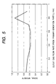
- Fig. 5 shows a result obtained by measuring when 1 L/min of argon gas is introduced into the primary ionization part 28 and 1 L/min of the sample gas is introduced into the secondary ionization part 23
- a flow rate of the argon gas to be discharged is up to 0.6 L/min, signal intensity of the ion gradually decreases; in the neighborhood of 0.7 L/min, the signal intensity of the ion is increased; and in the neighborhood of 0.8 L/min, it has a peak.
- the flow rate of the argon gas to be discharged is 0.8 L/min
- Fig. 6 is a view for explaining structure in which there is performed an online analysis of outlet gas from a fuel cell obtained by stacking a plurality of fuel cells as a single unit shown in Figs. 1, 3 as a stack in the example of the present invention.
- the structure of the branch 6 to the mass spectrometric part 11 shown in Fig. 1 has been omitted.
- sample gas inlet piping 7 to be connected to the branch 6 to be provided in the gas outlet piping 4 on cathode there flows a liquid intermediate product.
- the sample gas inlet piping 7 to the mass spectrometer is heated to vaporize the intermediate product, and it can be led to the mass spectrometer 8 for measurement.
- the mass spectrometer since traces of leak gas in the outlet gas of the fuel cell can be measured in a low limit of detection at high sensitivity, it is possible to construct a fuel cell inspection system for monitoring deterioration and defects in an electrolyte membrane online in an inspection process in the manufacture of the fuel cell.
- the electrolyte membrane is an important component element for affecting the performance, durability and service life of the fuel cell.
- a flow rate of gas to be consumed for the analysis is as low as about 0.1 L/min, and it is possible to measure without disturbing the system of fuel cell.
- an automotive fuel cell can be also inspected as below. That is, while a fuel replenishment station for fuel cells, for example, a hydrogen gas station is replenishing fuel to a fuel storage equipment, the crossover leak in the outlet gas of the fuel cell is inspected, whereby if the fuel cell is inspected, it will be possible to notify the driver of presence or absence of necessity for repair or replacement of the fuel cell. Since the inspection can be made during replenishment of fuel, there is no need for sparing excessive time for the inspection, but it is convenient for the driver.
- a fuel replenishment station for fuel cells for example, a hydrogen gas station is replenishing fuel to a fuel storage equipment
- a mass spectrometer capable of detecting impurity in sample gas of a low flow rate in a high sensitivity, to introduce a sample from a system targeted for inspection for analysis without disturbing the system targeted for inspection as far as possible, and to provide a mass spectrometer capable of detecting the crossover leak of the fuel cell, impurity in the inlet gas to the fuel cell, and impurity in the outlet gas from the fuel cell in a state in which the fuel cell has been operated without disturbing the operation system of the fuel cell online in a high sensitivity with the'target of inspection as, for example, the fuel cell.
Landscapes
- Chemical & Material Sciences (AREA)
- Analytical Chemistry (AREA)
- Life Sciences & Earth Sciences (AREA)
- Engineering & Computer Science (AREA)
- Manufacturing & Machinery (AREA)
- Sustainable Development (AREA)
- Sustainable Energy (AREA)
- Chemical Kinetics & Catalysis (AREA)
- Electrochemistry (AREA)
- General Chemical & Material Sciences (AREA)
- Other Investigation Or Analysis Of Materials By Electrical Means (AREA)
- Fuel Cell (AREA)
- Electron Tubes For Measurement (AREA)
Abstract
A mass spectrometer for detecting impurity in sample gas of a low flow rate e.g.effluent from a fuel cell (1), comprises an atmospheric pressure chemical ionization source having a primary ionization part (28) for generating a primary ion by means of electric discharge of reagent gas, and a secondary ionization part (23) for generating an ion of the sample by a reaction of the primary ion and the sample; a mass spectrometric part (11) for performing mass spectrometric analysis of the ion generated; a mixing portion (33) for mixing the sample to be introduced into the secondary ionization part with dilution gas; and means (30) for controlling the flow rate of the dilution gas for flowing through the mixing portion; and means 12-1 or 12-2 or 12-3 for controlling the flow rate of the sample gas, wherein mixed gas obtained by mixing the sample with the dilution gas is introduced into the secondary ionization part and the sample is ionized. <IMAGE>
Description
The present invention relates to a mass
spectrometer which detects impurity in sample gas of a
low flow rate in a high sensitivity by atmospheric
pressure chemical ionization.
There is known a gas analytical device using
GC-PID (Gas chromatography-photo-ionization detection),
or a sector type mass spectrometer using a magnetic
field. Also, there is known a semiconductor sensor for
detecting hydrogen.
An APCI-MS (Atmospheric Pressure Chemical
Ionization Mass Spectrometer) is a device which
selectively ionizes traces of components to be
contained in a sample by taking advantage of an ion
molecular reaction to detect in a high sensitivity, and
has been used for biotechnology such as protein
analysis and for impurity analysis in a semiconductor
process.
In an analysis of gas which is prone to
contaminate an ion source, a primary ionization part is
separated from a sample inlet part, whereby clean gas
is introduced into the primary ionization part to
generate a primary ion; sample gas introduced into the
sample inlet part is mixed with the primary ion
generated in the primary ionization part to ionize an
object substance to be contained in the sample gas by
an ion-molecule reaction (See Japanese Patent
Application Laid-Open No. 6-310091).
There has been requested a technique by which a
sample is sampled from a system targeted for inspection
without disturbing the system targeted for inspection
as far as possible and the system targeted for
inspection is inspected in a state in which the target
of inspection is maintained in a dynamic state.
For example, in development of a fuel cell, in
order to investigate mass balance of gas at inlet and
outlet of the fuel cell for evaluating the power
generation efficiency, it has become an important
problem to confirm how the efficiency changes by
changing parameters for temperature, flow rate and the
like. In order to evaluate performance of the fuel cell,
there has been increasing a request for measuring
analysis of gas components at inlet and outlet of the
fuel cell online.
In order to evaluate the performance of the
fuel cell, highly-sensitive detectability on the order
of ppm is requested. Detection sensitivity of hydrogen
by a semiconductor sensor is on the order of 0.1% to 1%,
and is insufficient in sensitivity. In an analysis due
to GC-PID, since a separation process by GC is required,
data can be obtained only at intervals of several
minutes at a minimum even if online type GC is used,
and a transient operation of the fuel cell cannot be
evaluated.
There has been known a sector type mass
spectrometer using a magnetic field capable of
continuously analyzing hydrogen concentration of the
fuel cell in real time, the sensitivity is generally on
the order of 0.1%, and a sampling flow rate.of about (3
to 4) L/min (liter/minute) is required.
A flow rate of each of hydrogen and air
necessary for an operation of the fuel cell is
generally about 1 L/min, and when a sampling flow rate
during an online analysis is high, a flow rate of
hydrogen and air during an ordinary operation becomes
different from that of hydrogen and air during an
online analysis. In other words, there is a problem
that it becomes difficult to accurately evaluate
performance of an operation system of the fuel cell and
the fuel cell.
Also, in an EI-MS (Electron Impact Mass
Spectrometer) in which ionization is performed in a
vacuum, since a multiplicity of fragment ions obtained
by decomposing an original ion are generated during
ionization, it is difficult to specify an ion derived
from hydrogen in gas sampled and to determine precise
concentration.
In the conventional technique, no consideration
has been given in sampling while the fuel cell is
maintained in a normal operating state without
disturbing a system targeted for inspection, for
example, an operating system of the fuel cell.
It is an object of the present invention to
provide a mass spectrometer which detects, in a high
sensitivity, impurity in sample gas of a low flow rate,
and to provide a mass spectrometer which analyzes
samples without disturbing a system targeted for
inspection as far as possible.
In a mass spectrometer according to the present
invention, a substance targeted for measurement on the
order of ppm in the sample is measured with as low a
sampling flow rate as about 0.1 L/min.
In a mass spectrometer according to the present
invention, there is used an atmospheric pressure
chemical two-step ionization source composed of: a
primary ionization part for generating primary ions by
means of electric discharge of reagent gas (gas for
generating a primary ion, argon or helium); and a
secondary ionization part for generating secondary ions
of a sample by a reaction of the primary ion and a
sample to be introduced from a sample inlet. The
primary ionization part is formed with an inlet for
introducing reagent gas and an outlet for discharging
gas for generating the primary ions. Between the
primary ionization part and the secondary ionization
part, there is arranged a counter electrode having a
hole through which the primary ions are caused to pass
through toward the secondary ionization part. The
secondary ionization part is maintained at negative
pressure as compared with the primary ionization part.
The ions generated in the secondary ionization
part is introduced into a mass spectrometric part which
has been evacuated in a high vacuum, through an
aperture, and mass spectrometric analysis is performed
by a mass spectrometer such as a quadrupole type mass
spectrometer, an ion trap type mass spectrometer, an
ion trap-TOF type (time of flight type) mass
spectrometer and a magnetic field type mass
spectrometer.
A sample introduced from a target of inspection
is mixed with dilution gas in a mixing portion, and is
introduced into the secondary ionization part at a
substantially constant flow rate (1 L/min). Flow rates
of dilution gas and the sample which are to flow into
the mixing portion are controlled by flow rate control
means respectively. A flow rate of the dilution gas for
flowing through the mixing portion is to be set higher
than that of the sample for flowing through the mixing
portion. For example, assuming that a flow rate of
dilution gas for flowing through the mixing portion is
0.9 L/min or higher, a flow rate of the sample for
flowing through the mixing portion is 0.1 L/min or
lower, and that of gas mixed in the mixing portion is
about 1 L/min, these will be introduced into the
secondary ionization part.
As described above, the flow rate of the sample
to be introduced from the target of inspection is
reduced, whereby an influence on the target of
inspection by the sampling can be reduced. In this
respect, when an outlet flow rate of the reagent gas to
the secondary ionization part is set within a range of
(0.1 to 0.3) L/min, a suitable sensitivity can be
obtained.
For the dilution gas, there will be selected
dilution gas which does not interfere with ionization
of a substance targeted for measurement in the sample.
There will be used dilution gas, ionization potential
of which is the same as or higher than ionization
potential of the substance targeted for measurement, or
dilution gas, proton affinity of which is the same as
or lower than that of the substance targeted for
measurement is used, whereby an influence of lowered
concentration of the substance targeted for measurement
due to mixing of the dilution gas can be mitigated even
at low sampling flow rate without interfering with the
ionization of the substance targeted for measurement.
When, for example, a polymer .elecrolyte fuel
cell is inspected, the sample is collected from an
inlet piping for introducing gas or liquid to the fuel
cell or an outlet piping for discharging-gas or liquid
from the fuel cell. A sample inlet of the secondary
ionization part and the above-described inlet piping or
outlet piping are connected together through a sample
inlet piping through which the sample collected is to
flow. To this sample inlet piping, there is connected a
dilution gas piping through which the dilution gas
flows. In the dilution gas piping, there is arranged
flow rate control means for controlling the flow rate
of the dilution gas, and in the sample inlet piping,
there is arranged flow rate control means for
controlling the flow rate of the sample collected. With
such structure, the substance targeted for measurement
in the sample collected can be analyzed online in real
time. It goes without saying that the sample collected
can be directly introduced into a sample inlet of the
secondary ionization part for being analyzed without
mixing with the dilution gas.
From a gas outlet piping on cathode of the
polymer electrolyte fuel cell, sample gas is collected,
traces of hydrogen in the sample gas is selectively
ionized through the use of any of argon, helium and
nitrogen as the dilution gas, and through the use of
the atmospheric pressure chemical two-step ionization
, source, and traces of hydrogen can be measured in a
high sensitivity online in real time.
In the following description, as a system
targeted for inspection, the polymer elecrolyte fuel
cell will be exemplified for description.
Fig. 3 is a view for explaining structure of a
polymer electrolyte fuel cell to which the present
invention is applied. As regards the polymer
electrolyte fuel cell 1 (PEFC), the development has
been pursued as an automotive and dispersal power
source or as a fuel cell for a household. As shown in
Fig. 3, hydrogen gas is introduced as fuel from a gas
inlet piping 2 on anode of the fuel cell, is discharged
from a gas outlet piping 4 on anode, air is introduced
from a gas inlet piping 3 on cathode, and is discharged
from a gas outlet piping 5 on cathode.
By a catalytic action of a polymer electrolyte
membrane 25, a hydrogen molecule is dissociated by a
hydrogen atom on anode, further emits electrons, proton
(H+) generated moves from an electrode 26 on anode to an
electrode 26 on cathode, and reacts with an oxygen
molecule in air to form water. At this time, an
electric current flows between the electrode 26 on
anode and the electrode 26 on cathode. In order to
evaluate performance of the fuel cell online, it
becomes necessary to measure concentration of hydrogen
that flows through the gas inlet piping 2 on anode, and
the gas outlet piping 4 on anode, and concentration of
oxygen, nitrogen, and water content, and the like that
flow through the gas inlet piping 3 on cathode and the
gas outlet piping 4 on cathode.
In evaluation of performance of a polymer
electrolyte membrane 25 of the fuel cell 1, it becomes
important to measure an amount of crossover leak. The
crossover leak is a phenomenon in which a hydrogen
molecule introduced to the anode side moves within the
membrane 25 toward the cathode side, for leaking on the
cathode side in a state of hydrogen molecule instead of
converting to proton by a catalytic action of a polymer
electrolyte membrane 25, and permeating the interior of
the membrane
The hydrogen molecule that has leaked on the
cathode side reacts vigorously with oxygen molecules in
air on the cathode side of the membrane 25 to
deteriorate the polymer electrolyte membrane 25 for
increasing the amount of crossover leak more and more.
Gradually, the electric power decreases and the fuel
cell becomes unable to sufficiently perform.
The concentration (amount of crossover leak) of
the hydrogen molecule that has leaked on the cathode
side can be determined by measuring concentration of
trace hydrogen in the gas for flowing through the gas
outlet piping 5 on cathode. This amount of crossover
leak is on several ppm level at least. For a device for
evaluating online an operating performance in a state
in which the fuel cell has been actuated, highly
sensitive detectability on the order of ppm is required
as described previously.
As a portable fuel cell the development of
which has been pursued for a portable computer or a
portable telephone, there is a Direct Methanol Fuel
Cell (DMFC). In the DMFC, methanol is introduced on the
anode side as fuel. Even in the case of performance
evaluation of the DMFC, it is important to measure the
crossover leak as in the case of the PEFC. In the DMFC,
when there is crossover leak, methanol permeates on the
cathode side and reacts with oxygen molecules
vigorously to deteriorate the membrane.
Therefore, in measurement of the crossover leak
of the DMFC, when measurement is performed in a state
in which the fuel cell is not operated, inactive gas
such as nitrogen and rare gas is introduced into the
gas inlet piping 3 on cathode, and there is measured
trace methanol to be contained in gas that flows
through the gas outlet piping 5 on cathode that has
leaked on the cathode side. When measurement is
performed in a state in which the fuel cell is operated,
the methanol that has permeated the membrane 25 is
changed into CO2 by the catalytic action of the membrane
25 on the cathode side, and therefore, there is
measured trace CO2 on the order of ppm to be contained
in gas that flows through the gas outlet piping 5 on
cathode.
Fig. 1 shows an example of the present
invention, and is a view explaining structure in which
outlet gas of a fuel cell is analyzed online through
the use of a mass spectrometer. As shown in Fig. 3, in
a fuel cell 1, there are connected together a gas inlet
piping 2 on anode for introducing hydrogen gas, a gas
outlet piping 4 on anode for discharging hydrogen gas
that has not been consumed, a gas inlet piping 3 on
cathode for introducing air, and a gas outlet piping 5
on cathode for discharging air.
To a branch 6 of the gas outlet piping 5 on
cathode, there is connected a sample gas inlet piping 7,
and the sample gas inlet piping 7 is connected to a
mass spectrometer 8. A dilution gas piping 9 in which a
mass flow controller 14 has been arranged is connected
to the sample gas inlet piping 7. The mass spectrometer
8 is composed of an ion source 10 and a mass
spectrometric part 11 evacuated in a high vacuum.
A portion or the whole quantity of gas
exhausted into the gas outlet piping 5 on cathode of
the fuel cell 1 is sampled in order to measure a
crossover leak of hydrogen. The gas thus sampled is (1)
introduced into the mass spectrometer 8 as it is as
sample gas, or (2) is mixed with dilution gas to be
introduced into the sample gas inlet piping 7 from the
dilution gas piping 9, and is introduced into the mass
spectrometer as sample gas containing hydrogen as
substance targeted for measurement.
The sample gas is introduced into the ion
source 10 by a pump 13. At this time, in order to
stabilize the sensitivity of the mass spectrometer, it
is important to make an amount of inlet of the sample
gas into the ion source 10 constant.
The flow rate of the sample gas is controlled
by a mass flow controller to be arranged in any of the
following (1), (2) and (3). (1) a mass flow controller
12-1 to be arranged in a sample gas inlet piping (in
Fig. 1, piping indicated by 7, in Fig. 2, piping
indicated by 31 through which the branch 6 of Fig. 1 is
connected to the dilution gas inlet 16) between the
branch 6 and a mixing portion 33 (will be described
later). (2) a mass flow controller 12-2 to be arranged
in a mixed gas inlet piping (in Fig. 1, piping
indicated by 7, in Fig. 2, piping indicated by 31
through which the branch 6 of Fig. 1 is connected to
the dilution gas inlet 16) between the mixing portion
33 and an ion source (although indicated by the
secondary ionization part 23 in Fig. 2, indicated by
the ion source 10 in Fig. 1). In other words, the mass
flow controller 12-2 is, as shown in Fig. 2, arranged
in the sample gas inlet piping between the mixing
portion 33 and the dilution gas inlet 16. (3) A mass
flow controller 12-3 to be arranged in the mixed gas
outlet piping between the ion source (although
indicated by the secondary ionization part 23 in Fig. 2,
indicated by the ion source 10 in Fig. 1) and the pump
13. In other words, the mass flow controller 12-3 is,
as shown in Fig. 2, arranged in the dilution gas outlet
piping between the mixed gas outlet 18 and the pump 13.
The flow rate of sample gas that flows from the
branch 6 of the gas outlet piping 5 on cathode to the
sample gas inlet piping 7 is controlled by the mass
flow controller 12-1 or 12-2 to be arranged in the
sample gas inlet piping 7. When there is a high
possibility that substance targeted for measurement
.contaminates the mass flow controller 12-1 or 12-2, the
mass flow controller 12-3 can be provided in piping
between the ion source 10 and the pump 13 for
controlling.
As the ion source 10, there is used an
atmospheric pressure chemical ionization source (APCI).
The APCI is a method for chemically ionizing traces of
molecules targeted for measurement in the sample from a
primary ion generated in the atmosphere by an ion-molecule
reaction, is advantageous in terms of
selectivity and sensitivity, it is possible to perform
soft ionization of a molecule targeted for measurement
because of low ionization energy, and has a feature
that it generates few fragment ions. For this reason,
it is effective to determine a substance of a low mass
number such as hydrogen. Particularly, a two-step ion
source, in which the primary ionization part is
separated from the secondary ionization part for
performing the secondary ionization, is particularly
effective to measure hydrogen.
Fig. 2 is a view showing detailed structure of
an ion source 10 according to an example of the present
invention, structure in which the sample is mixed with
gas (dilution gas). As shown in Fig. 2, the ion source
is composed of the primary ionization part 28 and the
secondary ionization part 23 for performing the
secondary ionization. The secondary ionization part is
maintained at negative pressure as compared with the
primary ionization part.
By means of the mass flow controller 12-1 or
12-2 to be arranged in the sample gas inlet piping 31
connected to the branch 6 shown in Fig. 1, or the mass
flow controller 12-3 to be arranged in the mixed gas
outlet piping between the mixed gas outlet 18 and the
pump 13, there are mixed sample gas from the sample gas
inlet piping 31, that has been controlled at a constant
flow rate, and dilution gas from a dilution gas tank 32,
that has been controlled at a constant flow rate by the
mass flow controller 30 to be arranged in the dilution
gas inlet piping 29 in a mixing portion 33 in which a
sample gas inlet piping 31 and a dilution gas inlet
piping 29 have been coupled with each other. Mixed
sample gas obtained by mixing the sample gas with the
dilution gas is introduced into the secondary
ionization part 23 of the ion source from a mixed
sample gas inlet 16.
As reagent gas, such as argon and helium, gas
having higher ionization potential than ion which
becomes an object of measurement or gas having lower
proton affinity is introduced into the primary
ionization part 28 from a reagent gas inlet piping 15.
Here, the description will be made of a case where
argon is used. Argon gas is ionized in the vicinity of
a needle electrode 21 to which high voltage of several
kV has been applied (Chemical Formula 1). In order to
stabilize the ionization, it is important that an inlet
amount of argon gas is controlled constant by a mass
flow controller 19 arranged in the reagent gas inlet
piping 15.
Ar → Ar+
Argon ions thus generated pass through a hole
of a counter electrode 22 together with a portion of
argon gas, and are introduced into the secondary
ionization unit 23. The remaining argon gas is
discharged through a reagent gas outlet piping 17, and
in order to make a flow rate of argon gas to be
introduced into the secondary ionization part 23
constant, the flow rate of the argon gas to be
discharged is controlled constant by the mass flow
controller 20 arranged in the reagent gas outlet piping
17.
In the secondary ionization part 23, the argon
gas and the primary ions (Ar+) are mixed with the sample
gas to cause a secondary ionization reaction. When the
sample gas containing hydrogen as a substance targeted
for measurement is air or nitrogen, ion (N2H+) which
becomes an object of measurement is generated by
reactions (Chemical Formula 2), (Chemical Formula 3) as
below.
Ar+ + N2 → N2 + + Ar
N2 + + H2 → N2H+ + H
The ion N2H+ thus generated is introduced into a
mass spectrometric part 11 evacuated in a high vacuum
through the aperture 24 for mass spectrometric analysis.
In order to increase an amount of ion N2H+ to be
introduced into the mass spectrometric part, there are
provided electrical potential gradients in the order of
the needle electrode 21, the counter electrode 22 and
the aperture 24, and the ion is drawn into the aperture
24 according to the electrical potential difference.
Gas mixed in the secondary ionization part 23
is partially introduced into the aperture 24 due to a
pressure difference, and the rest is exhausted through
the mixed gas outlet 18. As described above, even in
the flow rate of the sample gas, it is important to
control constant by the mass flow controller 12-1 or
12-2, or to control the flow rate of the dilution gas
constant by the mass flow controller 12-3 installed on
the exhaust side for exhausting the dilution gas from
the dilution gas outlet 18.
A flow rate of sample necessary for the
atmospheric pressure chemical ion source is about 1
L/min. As described above, a flow rate of gas to be
consumed in an online analysis using the mass
spectrometer is preferably as low as possible in order
not to disturb an operating system of the fuel cell.
As shown in Fig. 2, dilution gas is introduced
into the sample gas inlet piping 31 from the dilution
gas piping 29. As the dilution gas, such gas having low
proton affinity as not to disturb the reaction of
(Chemical Formula 3), for example, argon, helium or
nitrogen itself is also effective. Since ionization due
to the reaction of (Chemical Formula 3) is not
interfered because of the existence of the dilution gas
even if such dilution gas is mixed with the sample gas,
it is possible to mitigate an influence of lowered
concentration of the substance targeted for measurement
due to mixing of the dilution gas.
The maximum effect of mixing the dilution gas
with the gas sampled is to be able to reduce a flow
rate of gas to be sampled from the fuel cell. For a
flow rate necessary for gas for flowing into the
atmospheric pressure chemical ionization source, about
1 L/min will suffice. Therefore, since for total gas
flow rate after the sampled gas is mixed with the
dilution gas, about 1 L/min will suffice, if, for
example, the flow rate of the dilution gas is assumed
to be 0.9 L/min, for the flow rate of gas to be sampled
from the fuel cell, 0.1 L/min will suffice, and it
becomes possible to perform online analysis without
disturbing the system of fuel cell. In other words, the
flow rate of gas to be sampled from gas exhausted to
the gas outlet piping 5 on cathode of the fuel cell 1
is reduced as far as possible, whereby it is possible
not to affect the flow rate of gas for flowing on the
anode and cathode sides as far as possible.
As a mass spectrometer for use with the mass
spectrometric part 11, there is applicable a mass
spectrometer such as a quadrupole type mass
spectrometer, an ion trap type mass spectrometer, an
ion trap-TOF type mass spectrometer and a magnetic
field type mass spectrometer. Hereinafter, the
description will be made of an example of result in
which measurement has been made using the quadrupole
type mass spectrometer.
Fig. 4 is a view showing relationship between
concentration of hydrogen obtained by adding traces of
hydrogen to air in various concentrations for
measurement and S/N in an example of the present
invention. The ordinate of Fig. 4 indicates a ratio
(S/N) of noise N to signal intensity S of N2H+ (mass
number m/z= 29) ion. The result shown in Fig. 4 is a
result obtained by measuring assuming a flow rate of
the sample gas to be 1 L/min, and shows that hydrogen
concentration can be measured at a limit of detection
(S/N=3) of 0.5 ppm at high sensitivity.
Fig. 5 is a view showing relationship between a
flow rate of gas to be discharged from the primary
ionization part and sensitivity in the example of the
present invention, and shows signal intensity of N2H+
(mass number m/z= 29) ion measured when air added with
2.5 ppm of hydrogen is used as the sample gas in a case
where argon gas is introduced into the primary
ionization part 28 as reagent gas and a flow rate of
argon gas to be discharged from the reagent gas outlet
piping 17 is controlled and changed by the mass flow
controller 20.
Fig. 5 shows a result obtained by measuring
when 1 L/min of argon gas is introduced into the
primary ionization part 28 and 1 L/min of the sample
gas is introduced into the secondary ionization part 23
When a flow rate of the argon gas to be discharged is
up to 0.6 L/min, signal intensity of the ion gradually
decreases; in the neighborhood of 0.7 L/min, the signal
intensity of the ion is increased; and in the
neighborhood of 0.8 L/min, it has a peak. When the flow
rate of the argon gas to be discharged is 0.8 L/min,
the flow rate of argon gas which passes through a hole
of the counter electrode 22 together with the primary
ion Ar+ is (1 - 0.8) L/min = 0.2 L/min.
This shows that when an amount of gas which
flows through the hole of the counter electrode 22 is
too large, an influence of the sample gas being diluted
in the secondary ionization part 23 becomes large to
decrease the sensitivity, while when too small, it
becomes difficult for the primary ion to be stably
supplied to the secondary ionization part 23 through
the hole of the counter electrode 22 and an efficiency
of the secondary ionization in the secondary ionization
part 23 will be decreased. Therefore, an adequate
amount of gas for generating the primary ion when
passing through the hole of the counter electrode 22 is
(0.1 to 0.3) L/min.
Fig. 6 is a view for explaining structure in
which there is performed an online analysis of outlet
gas from a fuel cell obtained by stacking a plurality
of fuel cells as a single unit shown in Figs. 1, 3 as a
stack in the example of the present invention. In Fig.
6, the structure of the branch 6 to the mass
spectrometric part 11 shown in Fig. 1 has been omitted.
As shown in Fig. 6, it is possible to measure by
connecting the gas piping to the mass spectrometer so
as to branch it as in the case of Fig. 1, and it is
possible to inspect for any defective fuel cell by
measuring an amount of leak as the entire fuel cell
stack 27 online.
In the foregoing description, the description
has been made of structure and method for measuring the
crossover leak by sampling gas in the gas outlet piping
5 on cathode, and through the use of the similar
structure and method thereto, there is provided the
branch 6 in the gas inlet piping 2 on anode, the gas
inlet piping 3 on cathode, the gas outlet piping 4 on
anode, and the sample gas inlet piping 7 is connected
to the branch 6, whereby gas in these piping 2, 3, 4
can be sampled for analysis. Particularly, in the case
of the DMFC, methanol and water content are supplied to
the anode side as fuel. When measuring formic acid and
formaldehyde which are intermediate products, in the
sample gas inlet piping 7 to be connected to the branch
6 to be provided in the gas outlet piping 4 on cathode,
there flows a liquid intermediate product. The sample
gas inlet piping 7 to the mass spectrometer is heated
to vaporize the intermediate product, and it can be led
to the mass spectrometer 8 for measurement.
As described above, not only detection of the
crossover leak of the fuel cell, but also detection of
impurity in the gas to be introduced into the fuel cell
on the anode and cathode sides, and impurity in the gas
to be exhausted from the fuel cell on the anode side
can be performed at high sensitivity online without
disturbing the operating'system of the fuel cell in a
state in which the fuel cell has been operated.
In the mass spectrometer according to the
present invention, since traces of leak gas in the
outlet gas of the fuel cell can be measured in a low
limit of detection at high sensitivity, it is possible
to construct a fuel cell inspection system for
monitoring deterioration and defects in an electrolyte
membrane online in an inspection process in the
manufacture of the fuel cell. The electrolyte membrane
is an important component element for affecting the
performance, durability and service life of the fuel
cell.
In the present invention, it is possible to
measure at high speed by introducing inlet gas and
outlet gas of the fuel cell sampled directly or after
mixing with dilution gas into the atmospheric pressure
chemical two-step ionization source in which an ion-molecule
reaction is effectively performed, and
ionizing highly selectively and at high sensitivity for
analysis without the need for pretreatment of the
sample. Also, a flow rate of gas to be consumed for the
analysis is as low as about 0.1 L/min, and it is
possible to measure without disturbing the system of
fuel cell.
Through the use of an inspection device using a
mass spectrometer according to the present invention,
an automotive fuel cell can be also inspected as below.
That is, while a fuel replenishment station for fuel
cells, for example, a hydrogen gas station is
replenishing fuel to a fuel storage equipment, the
crossover leak in the outlet gas of the fuel cell is
inspected, whereby if the fuel cell is inspected, it
will be possible to notify the driver of presence or
absence of necessity for repair or replacement of the
fuel cell. Since the inspection can be made during
replenishment of fuel, there is no need for sparing
excessive time for the inspection, but it is convenient
for the driver.
According to the present invention, it is
possible to provide a mass spectrometer capable of
detecting impurity in sample gas of a low flow rate in
a high sensitivity, to introduce a sample from a system
targeted for inspection for analysis without disturbing
the system targeted for inspection as far as possible,
and to provide a mass spectrometer capable of detecting
the crossover leak of the fuel cell, impurity in the
inlet gas to the fuel cell, and impurity in the outlet
gas from the fuel cell in a state in which the fuel
cell has been operated without disturbing the operation
system of the fuel cell online in a high sensitivity
with the'target of inspection as, for example, the fuel
cell.
Claims (8)
- A mass spectrometer, comprising: an atmospheric pressure chemical ionization source having a primary ionization part for generating a primary ion by means of electric discharge of reagent gas, and a secondary ionization part for generating an ion of a sample by a reaction of said primary ion and said sample; a mass spectrometric part for performing mass spectrometric analysis of said ion generated; a mixing portion for mixing said sample to be introduced into said secondary ionization part with dilution gas; means for controlling a flow rate of said dilution gas for flowing through said mixing portion; and means for controlling a flow rate of said sample for flowing through said mixing portion, wherein mixed gas obtained by mixing said sample with said dilution gas is introduced into said secondary ionization part.
- The mass spectrometer according to Claim 1, wherein ionization potential of said dilution gas is the same as or higher than ionization potential of a substance targeted for measurement in said sample, or proton affinity of said dilution gas is the same as or lower than that of the substance targeted for measurement in said sample.
- The mass spectrometer according to Claim 2, wherein said sample is a sample to be collected from an inlet piping for introducing gas or liquid to a fuel cell or an outlet piping for discharging gas or liquid from said fuel cell.
- The mass spectrometer according to Claim 3, wherein gas for generating said primary ion is argon or helium.
- The mass spectrometer according to Claim 3, wherein an outlet flow rate of said reagent gas to said secondary ionization part is within a range of (0.1 to 0.3)L/min.
- A mass spectrometer, comprising: an atmospheric pressure chemical ionization source having a primary ionization part for generating a primary ion by means of electric discharge of reagent gas, and a secondary ionization part for generating an ion of said sample gas by a reaction of said primary ion and sample gas to be collected from gas outlet piping on cathode of a fuel cell; a mass spectrometric part for performing mass spectrometric analysis of said ion generated; a mixing portion for mixing said sample gas to be introduced into said secondary ionization part with dilution gas; means for controlling a flow rate of said dilution gas for flowing through said mixing portion; and means for controlling a flow rate of said sample gas for flowing through said mixing portion, wherein mixed gas obtained by mixing said sample gas with said dilution gas is introduced into said secondary ionization part, said dilution gas is any of argon, helium and nitrogen, and hydrogen in said sample gas is detected.
- The mass spectrometer according to Claim 6, wherein a flow rate of said dilution gas for flowing through said mixing portion is higher than that of said sample for flowing through said mixing portion.
- The mass spectrometer according to Claim 6, wherein an outlet flow rate of said reagent gas to said secondary ionization part is within a range of (0.1 to 0.3) L/min.
Applications Claiming Priority (2)
| Application Number | Priority Date | Filing Date | Title |
|---|---|---|---|
| JP2002324684 | 2002-11-08 | ||
| JP2002324684A JP2004157057A (en) | 2002-11-08 | 2002-11-08 | Mass spectrometer |
Publications (1)
| Publication Number | Publication Date |
|---|---|
| EP1418422A1 true EP1418422A1 (en) | 2004-05-12 |
Family
ID=32105488
Family Applications (1)
| Application Number | Title | Priority Date | Filing Date |
|---|---|---|---|
| EP20030024873 Withdrawn EP1418422A1 (en) | 2002-11-08 | 2003-10-31 | Mass spectrometer |
Country Status (4)
| Country | Link |
|---|---|
| US (1) | US6852970B2 (en) |
| EP (1) | EP1418422A1 (en) |
| JP (1) | JP2004157057A (en) |
| CA (1) | CA2447540A1 (en) |
Cited By (3)
| Publication number | Priority date | Publication date | Assignee | Title |
|---|---|---|---|---|
| EP1638132A3 (en) * | 2004-09-16 | 2007-03-14 | Hitachi Ltd. | Mass chromatography |
| DE102008061807A1 (en) * | 2008-12-11 | 2010-06-17 | Inficon Gmbh | Method for leak testing a stack of fuel cells |
| CN105181785A (en) * | 2015-03-19 | 2015-12-23 | 南昌大学 | Method for rapid discrimination of Cinnamomun camphcra of different chemotypes |
Families Citing this family (30)
| Publication number | Priority date | Publication date | Assignee | Title |
|---|---|---|---|---|
| US8173431B1 (en) | 1998-11-13 | 2012-05-08 | Flir Systems, Inc. | Mail screening to detect mail contaminated with biological harmful substances |
| US20060257287A1 (en) * | 1998-11-13 | 2006-11-16 | Call Charles J | Robust system for screening enclosed spaces for biological agents |
| US7759123B2 (en) * | 1998-11-13 | 2010-07-20 | Mesosystems Technology, Inc. | Removing surface deposits of concentrated collected particles |
| US7095019B1 (en) | 2003-05-30 | 2006-08-22 | Chem-Space Associates, Inc. | Remote reagent chemical ionization source |
| JP4384542B2 (en) * | 2004-05-24 | 2009-12-16 | 株式会社日立ハイテクノロジーズ | Mass spectrometer |
| JP2006196415A (en) * | 2005-01-17 | 2006-07-27 | Hitachi Ltd | Fuel cell inspection system |
| US7138626B1 (en) | 2005-05-05 | 2006-11-21 | Eai Corporation | Method and device for non-contact sampling and detection |
| US7568401B1 (en) | 2005-06-20 | 2009-08-04 | Science Applications International Corporation | Sample tube holder |
| GB2432711B (en) * | 2005-10-11 | 2008-04-02 | Gv Instr | Ion source preparation system |
| US7576322B2 (en) * | 2005-11-08 | 2009-08-18 | Science Applications International Corporation | Non-contact detector system with plasma ion source |
| US7758985B2 (en) * | 2005-12-21 | 2010-07-20 | American Power Conversion Corporation | Fuel cell sensors and methods |
| JP2008021521A (en) * | 2006-07-12 | 2008-01-31 | Ricoh Co Ltd | Fuel cell reaction analyzer and fuel cell operating state monitoring device |
| JP4867995B2 (en) * | 2006-12-20 | 2012-02-01 | 株式会社島津製作所 | Ionizer |
| WO2009023314A2 (en) * | 2007-05-09 | 2009-02-19 | Icx Technologies | Mail parcel screening using multiple detection technologies |
| US8123396B1 (en) | 2007-05-16 | 2012-02-28 | Science Applications International Corporation | Method and means for precision mixing |
| US8008617B1 (en) | 2007-12-28 | 2011-08-30 | Science Applications International Corporation | Ion transfer device |
| FR2927471B1 (en) * | 2008-02-12 | 2011-05-13 | Commissariat Energie Atomique | METHOD AND DEVICE FOR LIMITING CORROSION AGING OF THE CARBON CATHODE CATHODE SUPPORT OF PROTON EXCHANGE MEMBRANE FUEL CELLS |
| EP2091068A1 (en) | 2008-02-15 | 2009-08-19 | Nederlandse Organisatie voor toegepast- natuurwetenschappelijk onderzoek TNO | A sensor, a monitoring system and a method for detecting a substance in a gas sample |
| US8243274B2 (en) * | 2009-03-09 | 2012-08-14 | Flir Systems, Inc. | Portable diesel particulate monitor |
| US8071957B1 (en) | 2009-03-10 | 2011-12-06 | Science Applications International Corporation | Soft chemical ionization source |
| WO2010115142A2 (en) * | 2009-04-03 | 2010-10-07 | Mesosystems Technology Inc. | Method and apparatus for capturing viable biological particles over an extended period of time |
| EP2467706A1 (en) * | 2009-08-19 | 2012-06-27 | McGill University | Methods and systems for the quantitative chemical speciation of heavy metals and other toxic pollutants |
| CN103069538B (en) | 2010-08-19 | 2016-05-11 | 莱克公司 | There is the mass spectrograph of soft ionization glow discharge and adjuster |
| KR101459815B1 (en) * | 2011-11-30 | 2014-11-12 | 현대자동차주식회사 | Device and method for controlling hydrogen concentration of fuel cell system |
| US9093676B2 (en) * | 2012-10-29 | 2015-07-28 | Nissan North America, Inc. | Apparatus and method of in-situ measurement of membrane fluid crossover |
| JP6641218B2 (en) * | 2016-03-31 | 2020-02-05 | 岩谷産業株式会社 | Fuel hydrogen gas analyzer and analysis method |
| JP6741455B2 (en) * | 2016-03-31 | 2020-08-19 | 岩谷産業株式会社 | Analysis method and analyzer |
| CN113035686B (en) * | 2021-03-03 | 2023-06-16 | 桂林电子科技大学 | Ion source, FAIMS device and method for improving resolution and sensitivity of FAIMS device |
| US12113252B2 (en) * | 2022-05-13 | 2024-10-08 | ZeroAvia, Inc. | Detecting a fault condition in a fuel cell system |
| WO2025258486A1 (en) * | 2024-06-10 | 2025-12-18 | エーエムアール株式会社 | Ion introduction device and ion introduction method for introducing ions into mass spectrometer, mass spectrometry system, mass spectrometry method, ionization device, and ionization method |
Citations (3)
| Publication number | Priority date | Publication date | Assignee | Title |
|---|---|---|---|---|
| JPH06310091A (en) * | 1993-04-26 | 1994-11-04 | Hitachi Ltd | Atmospheric pressure ionization mass spectrometer |
| JPH11273615A (en) * | 1998-03-23 | 1999-10-08 | Hitachi Tokyo Electronics Co Ltd | Atmospheric ionization mass spectrometry and device |
| GB2347743A (en) * | 1999-01-25 | 2000-09-13 | Nippon Oxygen Co Ltd | Measuring trace impurities in a purified gas |
Family Cites Families (3)
| Publication number | Priority date | Publication date | Assignee | Title |
|---|---|---|---|---|
| US5969351A (en) * | 1996-02-07 | 1999-10-19 | Hitachi, Ltd. | Mass spectrometer |
| GB2324906B (en) * | 1997-04-29 | 2002-01-09 | Masslab Ltd | Ion source for a mass analyser and method of providing a source of ions for analysis |
| US7081620B2 (en) * | 2001-11-26 | 2006-07-25 | Hitachi High -Technologies Corporation | Atmospheric pressure ionization mass spectrometer system |
-
2002
- 2002-11-08 JP JP2002324684A patent/JP2004157057A/en not_active Abandoned
-
2003
- 2003-10-31 CA CA002447540A patent/CA2447540A1/en not_active Abandoned
- 2003-10-31 EP EP20030024873 patent/EP1418422A1/en not_active Withdrawn
- 2003-11-04 US US10/699,805 patent/US6852970B2/en not_active Expired - Fee Related
Patent Citations (4)
| Publication number | Priority date | Publication date | Assignee | Title |
|---|---|---|---|---|
| JPH06310091A (en) * | 1993-04-26 | 1994-11-04 | Hitachi Ltd | Atmospheric pressure ionization mass spectrometer |
| US5485016A (en) * | 1993-04-26 | 1996-01-16 | Hitachi, Ltd. | Atmospheric pressure ionization mass spectrometer |
| JPH11273615A (en) * | 1998-03-23 | 1999-10-08 | Hitachi Tokyo Electronics Co Ltd | Atmospheric ionization mass spectrometry and device |
| GB2347743A (en) * | 1999-01-25 | 2000-09-13 | Nippon Oxygen Co Ltd | Measuring trace impurities in a purified gas |
Non-Patent Citations (2)
| Title |
|---|
| HUNTER E J ET AL: "Detection of trace nitrogen in bulk argon using proton transfer reactions", JOURNAL OF VACUUM SCIENCE AND TECHNOLOGY A. VACUUM, SURFACES AND FILMS, AMERICAN INSTITUTE OF PHYSICS, NEW YORK, NY, US, vol. 16, no. 5, September 1998 (1998-09-01), pages 3127 - 3130, XP002193835, ISSN: 0734-2101 * |
| PATENT ABSTRACTS OF JAPAN vol. 2000, no. 1 * |
Cited By (3)
| Publication number | Priority date | Publication date | Assignee | Title |
|---|---|---|---|---|
| EP1638132A3 (en) * | 2004-09-16 | 2007-03-14 | Hitachi Ltd. | Mass chromatography |
| DE102008061807A1 (en) * | 2008-12-11 | 2010-06-17 | Inficon Gmbh | Method for leak testing a stack of fuel cells |
| CN105181785A (en) * | 2015-03-19 | 2015-12-23 | 南昌大学 | Method for rapid discrimination of Cinnamomun camphcra of different chemotypes |
Also Published As
| Publication number | Publication date |
|---|---|
| US6852970B2 (en) | 2005-02-08 |
| JP2004157057A (en) | 2004-06-03 |
| CA2447540A1 (en) | 2004-05-08 |
| US20040104342A1 (en) | 2004-06-03 |
Similar Documents
| Publication | Publication Date | Title |
|---|---|---|
| US6852970B2 (en) | Mass spectrometer | |
| EP1279940B1 (en) | Gas leak detection method for fuel cell | |
| US6949920B2 (en) | Apparatus for measuring current density of fuel cell | |
| US6475651B1 (en) | Method and apparatus for detecting transfer leaks in fuel cells | |
| EP4148848A1 (en) | Method and apparatus for detecting one or more leaks in a battery enclosure of a battery | |
| GB2582049A (en) | Method for operating an electrolysis system and electrolysis system | |
| US7695970B2 (en) | Optical fiber based fluorescence sensor for in-situ measurement and control of fuel cells | |
| US10724984B2 (en) | SP3 substituted carbon electrode TOC analysis using metallic catalyst | |
| US8314622B2 (en) | Method and apparatus for examining ion-conductive electrolyte membrane | |
| US20230022392A1 (en) | Sensor device for a fuel cell system | |
| Xu et al. | Effect of relative humidity on membrane degradation rate and mechanism in PEM fuel cells | |
| KR101294182B1 (en) | Apparatus and method for testing electrolyte membrane in fuel cell | |
| JP2006078226A (en) | Ion quantitative analysis method and fluorine ion quantitative analysis method | |
| Mittal et al. | H2O2 formation mechanism in PEMFC | |
| CN116879381A (en) | Online accurate quantitative photo-induced chemical ionization mass spectrum system and method for organic acid in atmosphere under different humidity | |
| Yamaji et al. | Evaluation of impurity levels in cathodes of seven different SOFC stacks and modules before and after long-term operation | |
| US10290479B2 (en) | Online monitoring of fuel cell reactions by desorption electrospray mass spectrometry | |
| JP2011163890A (en) | Ion component analyzing method, and ion component analyzer | |
| CN118584384A (en) | Battery performance degradation testing device and method | |
| JP2006338978A (en) | Method for evaluating flow of reaction gas in fuel cell, evaluation device, fuel cell for evaluation | |
| US20230317991A1 (en) | Locating Degraded Cells in a Polymer Electrolyte Membrane Fuel Cell Stack | |
| KR20200080842A (en) | Examination Device of detecting Damage of Membrane for Fuel Cell and Detecting Method using the same | |
| CN114203517A (en) | Method for Proton Transfer Reaction Induced by Dichloromethane Induced by Radio Frequency Discharge | |
| Bettermann et al. | On-Line Gas Measurements Within PEM Fuel Cell Flow Fields by Electric Arc Emission Spectroscopy | |
| Bettermann et al. | On-Line Gas Measurements from PEM Fuel Cell Flow Fields by Electric Arc Emission Spectroscopy |
Legal Events
| Date | Code | Title | Description |
|---|---|---|---|
| PUAI | Public reference made under article 153(3) epc to a published international application that has entered the european phase |
Free format text: ORIGINAL CODE: 0009012 |
|
| AK | Designated contracting states |
Kind code of ref document: A1 Designated state(s): AT BE BG CH CY CZ DE DK EE ES FI FR GB GR HU IE IT LI LU MC NL PT RO SE SI SK TR |
|
| AX | Request for extension of the european patent |
Extension state: AL LT LV MK |
|
| 17P | Request for examination filed |
Effective date: 20041103 |
|
| AKX | Designation fees paid |
Designated state(s): DE FR GB |
|
| 17Q | First examination report despatched |
Effective date: 20080313 |
|
| STAA | Information on the status of an ep patent application or granted ep patent |
Free format text: STATUS: THE APPLICATION IS DEEMED TO BE WITHDRAWN |
|
| 18D | Application deemed to be withdrawn |
Effective date: 20080724 |