EP1418354A2 - Thrust roller bearing and cage - Google Patents
Thrust roller bearing and cage Download PDFInfo
- Publication number
- EP1418354A2 EP1418354A2 EP20030025684 EP03025684A EP1418354A2 EP 1418354 A2 EP1418354 A2 EP 1418354A2 EP 20030025684 EP20030025684 EP 20030025684 EP 03025684 A EP03025684 A EP 03025684A EP 1418354 A2 EP1418354 A2 EP 1418354A2
- Authority
- EP
- European Patent Office
- Prior art keywords
- roller
- cage
- needle
- length
- Prior art date
- Legal status (The legal status is an assumption and is not a legal conclusion. Google has not performed a legal analysis and makes no representation as to the accuracy of the status listed.)
- Granted
Links
- 238000005256 carbonitriding Methods 0.000 claims description 19
- 229910052751 metal Inorganic materials 0.000 claims description 5
- 239000002184 metal Substances 0.000 claims description 4
- 238000005096 rolling process Methods 0.000 claims 1
- 239000003921 oil Substances 0.000 abstract description 51
- 239000010687 lubricating oil Substances 0.000 abstract description 25
- 238000005299 abrasion Methods 0.000 description 50
- 238000000034 method Methods 0.000 description 37
- 238000010438 heat treatment Methods 0.000 description 23
- 238000005553 drilling Methods 0.000 description 22
- 238000010791 quenching Methods 0.000 description 20
- 230000000171 quenching effect Effects 0.000 description 18
- 229910000831 Steel Inorganic materials 0.000 description 17
- 239000010959 steel Substances 0.000 description 17
- 238000012360 testing method Methods 0.000 description 16
- 238000004519 manufacturing process Methods 0.000 description 15
- 238000005496 tempering Methods 0.000 description 15
- IJGRMHOSHXDMSA-UHFFFAOYSA-N Atomic nitrogen Chemical compound N#N IJGRMHOSHXDMSA-UHFFFAOYSA-N 0.000 description 14
- 239000007789 gas Substances 0.000 description 12
- 230000002093 peripheral effect Effects 0.000 description 12
- 239000000463 material Substances 0.000 description 9
- QGZKDVFQNNGYKY-UHFFFAOYSA-N Ammonia Chemical compound N QGZKDVFQNNGYKY-UHFFFAOYSA-N 0.000 description 8
- 230000002159 abnormal effect Effects 0.000 description 8
- 238000005259 measurement Methods 0.000 description 8
- 238000005255 carburizing Methods 0.000 description 7
- 229910052757 nitrogen Inorganic materials 0.000 description 7
- 229910001566 austenite Inorganic materials 0.000 description 6
- 238000005452 bending Methods 0.000 description 5
- 238000003754 machining Methods 0.000 description 5
- 238000005121 nitriding Methods 0.000 description 5
- 238000011056 performance test Methods 0.000 description 5
- 238000005461 lubrication Methods 0.000 description 4
- VNWKTOKETHGBQD-UHFFFAOYSA-N methane Chemical compound C VNWKTOKETHGBQD-UHFFFAOYSA-N 0.000 description 4
- 238000003825 pressing Methods 0.000 description 4
- 238000004080 punching Methods 0.000 description 4
- ATUOYWHBWRKTHZ-UHFFFAOYSA-N Propane Chemical compound CCC ATUOYWHBWRKTHZ-UHFFFAOYSA-N 0.000 description 3
- 229910021529 ammonia Inorganic materials 0.000 description 3
- 238000007796 conventional method Methods 0.000 description 3
- 238000010586 diagram Methods 0.000 description 3
- 238000000227 grinding Methods 0.000 description 3
- 238000010348 incorporation Methods 0.000 description 3
- FXNGWBDIVIGISM-UHFFFAOYSA-N methylidynechromium Chemical group [Cr]#[C] FXNGWBDIVIGISM-UHFFFAOYSA-N 0.000 description 3
- 230000002265 prevention Effects 0.000 description 3
- 238000003466 welding Methods 0.000 description 3
- 230000005540 biological transmission Effects 0.000 description 2
- 239000000112 cooling gas Substances 0.000 description 2
- 238000005520 cutting process Methods 0.000 description 2
- 230000006866 deterioration Effects 0.000 description 2
- 238000011161 development Methods 0.000 description 2
- 238000005530 etching Methods 0.000 description 2
- 150000002500 ions Chemical class 0.000 description 2
- 239000000203 mixture Substances 0.000 description 2
- 229910000069 nitrogen hydride Inorganic materials 0.000 description 2
- 230000003287 optical effect Effects 0.000 description 2
- 238000005498 polishing Methods 0.000 description 2
- 150000003839 salts Chemical class 0.000 description 2
- OKTJSMMVPCPJKN-UHFFFAOYSA-N Carbon Chemical compound [C] OKTJSMMVPCPJKN-UHFFFAOYSA-N 0.000 description 1
- OTMSDBZUPAUEDD-UHFFFAOYSA-N Ethane Chemical compound CC OTMSDBZUPAUEDD-UHFFFAOYSA-N 0.000 description 1
- PWHULOQIROXLJO-UHFFFAOYSA-N Manganese Chemical compound [Mn] PWHULOQIROXLJO-UHFFFAOYSA-N 0.000 description 1
- XUIMIQQOPSSXEZ-UHFFFAOYSA-N Silicon Chemical compound [Si] XUIMIQQOPSSXEZ-UHFFFAOYSA-N 0.000 description 1
- 238000005275 alloying Methods 0.000 description 1
- 229910001563 bainite Inorganic materials 0.000 description 1
- 230000000903 blocking effect Effects 0.000 description 1
- 238000007664 blowing Methods 0.000 description 1
- 229910052799 carbon Inorganic materials 0.000 description 1
- 239000003054 catalyst Substances 0.000 description 1
- 239000010960 cold rolled steel Substances 0.000 description 1
- 238000001816 cooling Methods 0.000 description 1
- 230000000694 effects Effects 0.000 description 1
- 230000002708 enhancing effect Effects 0.000 description 1
- 238000001125 extrusion Methods 0.000 description 1
- 238000005242 forging Methods 0.000 description 1
- 238000004093 laser heating Methods 0.000 description 1
- 239000007788 liquid Substances 0.000 description 1
- 229910052748 manganese Inorganic materials 0.000 description 1
- 239000011572 manganese Substances 0.000 description 1
- 229910000734 martensite Inorganic materials 0.000 description 1
- 238000000691 measurement method Methods 0.000 description 1
- 239000001294 propane Substances 0.000 description 1
- 238000000926 separation method Methods 0.000 description 1
- 229910052710 silicon Inorganic materials 0.000 description 1
- 239000010703 silicon Substances 0.000 description 1
- MNWBNISUBARLIT-UHFFFAOYSA-N sodium cyanide Chemical compound [Na+].N#[C-] MNWBNISUBARLIT-UHFFFAOYSA-N 0.000 description 1
- LIXWSNVLHFNXAJ-UHFFFAOYSA-N sodium;oxidoazaniumylidynemethane Chemical group [Na+].[O-][N+]#[C-] LIXWSNVLHFNXAJ-UHFFFAOYSA-N 0.000 description 1
Images




Classifications
-
- F—MECHANICAL ENGINEERING; LIGHTING; HEATING; WEAPONS; BLASTING
- F16—ENGINEERING ELEMENTS AND UNITS; GENERAL MEASURES FOR PRODUCING AND MAINTAINING EFFECTIVE FUNCTIONING OF MACHINES OR INSTALLATIONS; THERMAL INSULATION IN GENERAL
- F16C—SHAFTS; FLEXIBLE SHAFTS; ELEMENTS OR CRANKSHAFT MECHANISMS; ROTARY BODIES OTHER THAN GEARING ELEMENTS; BEARINGS
- F16C33/00—Parts of bearings; Special methods for making bearings or parts thereof
- F16C33/30—Parts of ball or roller bearings
- F16C33/34—Rollers; Needles
-
- F—MECHANICAL ENGINEERING; LIGHTING; HEATING; WEAPONS; BLASTING
- F16—ENGINEERING ELEMENTS AND UNITS; GENERAL MEASURES FOR PRODUCING AND MAINTAINING EFFECTIVE FUNCTIONING OF MACHINES OR INSTALLATIONS; THERMAL INSULATION IN GENERAL
- F16C—SHAFTS; FLEXIBLE SHAFTS; ELEMENTS OR CRANKSHAFT MECHANISMS; ROTARY BODIES OTHER THAN GEARING ELEMENTS; BEARINGS
- F16C19/00—Bearings with rolling contact, for exclusively rotary movement
- F16C19/22—Bearings with rolling contact, for exclusively rotary movement with bearing rollers essentially of the same size in one or more circular rows, e.g. needle bearings
- F16C19/30—Bearings with rolling contact, for exclusively rotary movement with bearing rollers essentially of the same size in one or more circular rows, e.g. needle bearings for axial load mainly
- F16C19/305—Bearings with rolling contact, for exclusively rotary movement with bearing rollers essentially of the same size in one or more circular rows, e.g. needle bearings for axial load mainly consisting of rollers held in a cage
-
- F—MECHANICAL ENGINEERING; LIGHTING; HEATING; WEAPONS; BLASTING
- F16—ENGINEERING ELEMENTS AND UNITS; GENERAL MEASURES FOR PRODUCING AND MAINTAINING EFFECTIVE FUNCTIONING OF MACHINES OR INSTALLATIONS; THERMAL INSULATION IN GENERAL
- F16C—SHAFTS; FLEXIBLE SHAFTS; ELEMENTS OR CRANKSHAFT MECHANISMS; ROTARY BODIES OTHER THAN GEARING ELEMENTS; BEARINGS
- F16C33/00—Parts of bearings; Special methods for making bearings or parts thereof
- F16C33/30—Parts of ball or roller bearings
- F16C33/46—Cages for rollers or needles
- F16C33/48—Cages for rollers or needles for multiple rows of rollers or needles
-
- F—MECHANICAL ENGINEERING; LIGHTING; HEATING; WEAPONS; BLASTING
- F16—ENGINEERING ELEMENTS AND UNITS; GENERAL MEASURES FOR PRODUCING AND MAINTAINING EFFECTIVE FUNCTIONING OF MACHINES OR INSTALLATIONS; THERMAL INSULATION IN GENERAL
- F16C—SHAFTS; FLEXIBLE SHAFTS; ELEMENTS OR CRANKSHAFT MECHANISMS; ROTARY BODIES OTHER THAN GEARING ELEMENTS; BEARINGS
- F16C33/00—Parts of bearings; Special methods for making bearings or parts thereof
- F16C33/30—Parts of ball or roller bearings
- F16C33/46—Cages for rollers or needles
- F16C33/54—Cages for rollers or needles made from wire, strips, or sheet metal
- F16C33/541—Details of individual pockets, e.g. shape or roller retaining means
-
- F—MECHANICAL ENGINEERING; LIGHTING; HEATING; WEAPONS; BLASTING
- F16—ENGINEERING ELEMENTS AND UNITS; GENERAL MEASURES FOR PRODUCING AND MAINTAINING EFFECTIVE FUNCTIONING OF MACHINES OR INSTALLATIONS; THERMAL INSULATION IN GENERAL
- F16C—SHAFTS; FLEXIBLE SHAFTS; ELEMENTS OR CRANKSHAFT MECHANISMS; ROTARY BODIES OTHER THAN GEARING ELEMENTS; BEARINGS
- F16C33/00—Parts of bearings; Special methods for making bearings or parts thereof
- F16C33/30—Parts of ball or roller bearings
- F16C33/46—Cages for rollers or needles
- F16C33/54—Cages for rollers or needles made from wire, strips, or sheet metal
- F16C33/542—Cages for rollers or needles made from wire, strips, or sheet metal made from sheet metal
- F16C33/547—Cages for rollers or needles made from wire, strips, or sheet metal made from sheet metal from two parts, e.g. two discs or rings joined together
-
- F—MECHANICAL ENGINEERING; LIGHTING; HEATING; WEAPONS; BLASTING
- F16—ENGINEERING ELEMENTS AND UNITS; GENERAL MEASURES FOR PRODUCING AND MAINTAINING EFFECTIVE FUNCTIONING OF MACHINES OR INSTALLATIONS; THERMAL INSULATION IN GENERAL
- F16C—SHAFTS; FLEXIBLE SHAFTS; ELEMENTS OR CRANKSHAFT MECHANISMS; ROTARY BODIES OTHER THAN GEARING ELEMENTS; BEARINGS
- F16C33/00—Parts of bearings; Special methods for making bearings or parts thereof
- F16C33/30—Parts of ball or roller bearings
- F16C33/46—Cages for rollers or needles
- F16C33/56—Selection of substances
-
- F—MECHANICAL ENGINEERING; LIGHTING; HEATING; WEAPONS; BLASTING
- F16—ENGINEERING ELEMENTS AND UNITS; GENERAL MEASURES FOR PRODUCING AND MAINTAINING EFFECTIVE FUNCTIONING OF MACHINES OR INSTALLATIONS; THERMAL INSULATION IN GENERAL
- F16C—SHAFTS; FLEXIBLE SHAFTS; ELEMENTS OR CRANKSHAFT MECHANISMS; ROTARY BODIES OTHER THAN GEARING ELEMENTS; BEARINGS
- F16C33/00—Parts of bearings; Special methods for making bearings or parts thereof
- F16C33/30—Parts of ball or roller bearings
- F16C33/66—Special parts or details in view of lubrication
- F16C33/6637—Special parts or details in view of lubrication with liquid lubricant
- F16C33/6681—Details of distribution or circulation inside the bearing, e.g. grooves on the cage or passages in the rolling elements
-
- F—MECHANICAL ENGINEERING; LIGHTING; HEATING; WEAPONS; BLASTING
- F16—ENGINEERING ELEMENTS AND UNITS; GENERAL MEASURES FOR PRODUCING AND MAINTAINING EFFECTIVE FUNCTIONING OF MACHINES OR INSTALLATIONS; THERMAL INSULATION IN GENERAL
- F16C—SHAFTS; FLEXIBLE SHAFTS; ELEMENTS OR CRANKSHAFT MECHANISMS; ROTARY BODIES OTHER THAN GEARING ELEMENTS; BEARINGS
- F16C2240/00—Specified values or numerical ranges of parameters; Relations between them
- F16C2240/40—Linear dimensions, e.g. length, radius, thickness, gap
-
- F—MECHANICAL ENGINEERING; LIGHTING; HEATING; WEAPONS; BLASTING
- F16—ENGINEERING ELEMENTS AND UNITS; GENERAL MEASURES FOR PRODUCING AND MAINTAINING EFFECTIVE FUNCTIONING OF MACHINES OR INSTALLATIONS; THERMAL INSULATION IN GENERAL
- F16C—SHAFTS; FLEXIBLE SHAFTS; ELEMENTS OR CRANKSHAFT MECHANISMS; ROTARY BODIES OTHER THAN GEARING ELEMENTS; BEARINGS
- F16C2240/00—Specified values or numerical ranges of parameters; Relations between them
- F16C2240/40—Linear dimensions, e.g. length, radius, thickness, gap
- F16C2240/54—Surface roughness
-
- F—MECHANICAL ENGINEERING; LIGHTING; HEATING; WEAPONS; BLASTING
- F16—ENGINEERING ELEMENTS AND UNITS; GENERAL MEASURES FOR PRODUCING AND MAINTAINING EFFECTIVE FUNCTIONING OF MACHINES OR INSTALLATIONS; THERMAL INSULATION IN GENERAL
- F16C—SHAFTS; FLEXIBLE SHAFTS; ELEMENTS OR CRANKSHAFT MECHANISMS; ROTARY BODIES OTHER THAN GEARING ELEMENTS; BEARINGS
- F16C2361/00—Apparatus or articles in engineering in general
- F16C2361/61—Toothed gear systems, e.g. support of pinion shafts
-
- F—MECHANICAL ENGINEERING; LIGHTING; HEATING; WEAPONS; BLASTING
- F16—ENGINEERING ELEMENTS AND UNITS; GENERAL MEASURES FOR PRODUCING AND MAINTAINING EFFECTIVE FUNCTIONING OF MACHINES OR INSTALLATIONS; THERMAL INSULATION IN GENERAL
- F16C—SHAFTS; FLEXIBLE SHAFTS; ELEMENTS OR CRANKSHAFT MECHANISMS; ROTARY BODIES OTHER THAN GEARING ELEMENTS; BEARINGS
- F16C43/00—Assembling bearings
- F16C43/04—Assembling rolling-contact bearings
- F16C43/06—Placing rolling bodies in cages or bearings
- F16C43/065—Placing rolling bodies in cages or bearings in cages
Definitions
- the present invention relates to a thrust roller bearing used in an automatic transmission and a compressor in an automobile, as well as to a cage used therein.
- a thrust roller bearing is constituted of a needle roller, a cage and a roller bearing ring, and has such a structure that the needle roller and the roller bearing ring are in line contact. Accordingly, high load-carrying capacity and high rigidity can be obtained for a small bearing projected area.
- the thrust roller bearing is suitable as a bearing used in a harsh condition of use, such as poor lubrication or high-speed rotation, and widely used as a bearing for an automatic transmission or a bearing for a compressor of an air-conditioner in an automobile, for example.
- Fig. 15A shows a roller holding portion provided in a pocket for accommodating a conventional needle roller.
- Fig. 15A shows a single-row roller
- Fig. 15B shows a multiple-row roller.
- a pocket 105 accommodating needle rollers 102, 102a, 102b has a length Lp slightly larger than a length L of the needle roller.
- a roller holding portion 105a is provided on a periphery of a window in parallel to a central axis of the pocket, and projects toward the needle roller side above the needle roller axis.
- roller holding portion 105a is provided on an entire periphery of the window in parallel to the axis.
- opening area that is, a gap is inevitably small, and performance of oil passage to the inside of the cage is not sufficient.
- a thrust roller bearing 50 includes a needle roller 80 and two annular cages 60, 70.
- Two cages 60, 70 are arranged so as to sandwich the needle roller from above and below, and have a window 61 of the upper cage and a window 71 of the lower cage respectively.
- windows have a length larger than the roller length in a radial direction respectively.
- Roller holding portions 64, 74 formed in such plurality of windows sandwich and hold a plurality of needle rollers 80.
- roller holding portions 64, 74 have a length 1a in the radial direction shorter than a roller length 1.
- at least one of two cages 60, 70 is bent so that at least one of thickness t1 of a radially outer portion 62 (72) and thickness t2 of a radially inner portion 63 (73) of the roller holding portion is made smaller than thickness t0 of the roller holding portion.
- a gap is enlarged in at least one of the radially outer portion and the radially inner portion having a thickness smaller than the roller holding portion. Accordingly, flow-in performance or flow-out performance of the lubricating oil passing through the gap is improved, and an amount of lubricating oil passing through the bearing per unit time can be increased. In addition, blocking by the cage of passage of the lubricating oil does not tend to occur, and stay of the lubricating oil is prevented. Consequently, temperature increase in the oil can be suppressed, thereby improving durability of the bearing.
- An object of the present invention is to provide a thrust roller bearing having improved oil passage performance of a lubricating oil in the inside of a bearing while holding a needle roller in a stable manner, as well as a cage.
- a cage having a hardened case so as not to cause a crack during working and in use, while suppressing abrasion and attaining a short time period for treatment, as well as a thrust roller bearing incorporating the cage are provided.
- a thrust roller bearing of the present invention different from the two thrust roller bearings in the invention above, a thrust roller bearing unlikely to suffer from drilling abrasion and attaining lower bearing noise is provided.
- thrust roller bearings are in common in higher durability, and the object of each thrust roller bearing is summarized as improvement in durability.
- the thrust roller bearing and the cage according to the present invention do not necessarily satisfy all of the three individual objects, but should only satisfy any one of those three objects. It goes without saying that two or more of the three objects above may be satisfied.
- a thrust roller bearing according to the present invention includes a needle roller, a cage holding the needle roller in a pocket for accommodating the needle roller, and a pair of roller bearing rings in contact with the needle roller so as to sandwich the needle roller and the cage.
- a roller holding portion provided in the pocket has a length within a range of 30% to 80% of a length in a radial direction of the pocket.
- roller holding portion has the length less than 30% of the length in the radial direction of the pocket, it is difficult to hold the needle roller in a stable manner.
- the roller holding portion has the length more than 80% of the length in the radial direction of the pocket, passage of the lubricating oil is blocked and the oil passage performance is deteriorated. Therefore, long-time use will cause temperature increase in the lubricating oil, resulting in deterioration in durability of the thrust roller bearing.
- the roller holding portion From the viewpoint of ensured holding of the needle roller, it is more preferable for the roller holding portion to have a length not smaller than 40% of the length in the radial direction of the pocket. From the viewpoint of improvement in the oil passage performance, it is more preferable for the roller holding portion to have a length not larger than 70% of the length in the radial direction of the pocket.
- roller holding portion described above is usually formed in a symmetrical manner, it may be formed asymmetrically.
- a shape of the roller holding portion formed on a right periphery and a shape of the roller holding portion formed on a left periphery of the window of the pocket may not be symmetrical with respect to the central axis of the window of the pocket.
- a length of one roller holding portion having a smaller length in the radial direction (if the roller holding portion is divided into a plurality of sections, one having smaller total length) is set to be not smaller than 30% of the length in the radial direction of the pocket, and a length of the other roller holding portion having a larger length in the radial direction (if the roller holding portion is divided into a plurality of sections, one having larger total length) is set to be not larger than 80% of the length in the radial direction of the pocket.
- the roller holding portion described above is constituted of a plurality of roller holding portions.
- the roller holding portion may be structured so that the total length of the plurality of roller holding portions is within a range of 30% to 80% of the length in the radial direction of the pocket.
- the roller holding portion By implementing the roller holding portion with the plurality of roller holding portions separate from each other, between two opposing factors of holding the roller and securing the oil passage performance, for example, the oil passage performance can be maximized on a presumption that minimum holding of the roller is attained in view of practical use.
- the plurality of roller holding portions may be adapted to a multiple-row roller for example, or alternatively, they may be adapted to a single-row roller.
- the roller by implementing an arrangement of the plurality of roller holding portions, in addition to improving the oil passage performance, the roller can be held and guided over a larger length. Thus, stable rotation can be achieved.
- the needle roller described above may be constituted of multiple roller rows, and a roller holding portion having a length smaller than that of the needle roller may be provided in respective one of multiple roller rows.
- the needle roller may be constituted of multiple roller rows, and the multiple-row needle roller may be held by one common roller holding portion. With such a structure, a process for forming the roller holding portion is simplified.
- Another thrust roller bearing according to the present invention includes a plurality of rollers, and a cage made of metal and holding the roller so as to sandwich the same with an upper member (upper cage) and a lower member (lower cage).
- a nitrocarburized case is formed to a depth in a range larger than 3 ⁇ m and smaller than 100 ⁇ m in a surface of the cage.
- the depth of the nitrocarburized case of the cage is set to be within a prescribed range.
- the depth of the nitrocarburized case in the surface portion is equal to or less than 3 ⁇ m, the abnormal abrasion described above cannot be avoided.
- the depth of the nitrocarburized case in the surface portion is equal to or larger than 100 ⁇ m, a crack may be produced in the caulked portion in caulking during assembly of the cage. More desirably, the depth of the nitrocarburized case is in a range of not smaller than 5 ⁇ m and not larger than 50 ⁇ m.
- the depth of the nitrocarburized case described above may be (A1) a depth of a degraded layer observed with an optical microscope after polishing and lightly etching the profile section.
- the depth of the nitrocarburized case may be (A2) a distance from the surface in a position having a hardness substantially equal to the inside hardness, which hardness is measured in a prescribed pitch, for example, a pitch of 0.5 ⁇ m, from the surface.
- the depth of the nitrocarburized case found by using at least one of the measurement methods of (A1) and (A2) should only be within the range described above. It is to be noted that the nitrocarburized case described above is also formed on the surface of a thin steel plate material, or on an end surface formed by providing an opening in the thin steel plate.
- the nitrocarburized case described above may be replaced by any surface hardening treatment described below. Alternatively, it may be replaced with a hardened case replaced by a hardening treatment other than the treatment described below.
- the hardened case is formed not only on a flat surface of the thin plate material but also on an end face formed by providing a window in the cage (section profile of a thickness of the thin plate material).
- Yet another thrust roller bearing according to the present invention includes a roller, and a cage holding the roller so as to sandwich the same with an upper member (upper cage) and a lower member (lower cage).
- a nitrocarburized case is formed to a depth in a range larger than 3 ⁇ m and smaller than 100 ⁇ m in its surface.
- the upper member and the lower member are superposed and bent in at least one of a radially outer end portion and a radially inner end portion thereof, and subjected to caulking.
- the nitrocarburized case plastically deforms in the caulked portion.
- the upper member and the lower member of the cage are subjected to press working for providing a pocket and for opening a window in the pocket for example, the upper member and the lower member are subjected to nitrocarburizing treatment, to form a hardened case on the surface.
- the roller is set in the pocket.
- the upper member and the lower member can be superposed and bent, and subjected to caulking.
- the process described above for example, it is not necessary to subject the superposed and bent portion to softening or the like, thereby simplifying the manufacturing process.
- the process can thus be simplified because the upper member and the lower member can be subjected to caulking with the nitrocarburized case present, which resulted from the fact that a depth of the nitrocarburized case has been set to be smaller than 100 ⁇ m.
- nitrocarburized case has been bent can be verified by observation with naked eyes or an optical microscope after polishing and lightly etching that portion. It is possible to observe that the nitrocarburized case has plastically deformed.
- the nitrocarburized case described above can be formed in a following manner.
- nitriding with low surface nitrogen concentration is performed with such a method as: (a1) a method of immersing a cage into molten salt having lowered nitriding capability, which molten salt is NaCNO obtained by blowing air into NaCN in advance; or (a2) a method of carbo-nitriding in an atmosphere obtained by adding ammonia (NH 3 ) to carburization gas.
- a1 a method of immersing a cage into molten salt having lowered nitriding capability, which molten salt is NaCNO obtained by blowing air into NaCN in advance
- NH 3 ammonia
- the nitrocarburized case described above can be replaced by a hardened case hardened with a different method.
- it may be replaced with a hardened case formed by heat treatment including quenching treatment.
- a hardened case formed by heat treatment including quenching treatment By setting the percentage of content of an alloying element such as carbon, silicon or manganese to be within an appropriate range in a composition of steel, a prescribed quench hardening capability is ensured, and a quench hardened structure of martensite or bainite can be formed on the surface portion.
- Such a structure may be quenched by heating only the surface portion with high-frequency heating or laser heating, or may be quenched by uniform heating of the entire body. After such quenching, tempering may or may not be applied.
- the nitrocarburized case described above may be replaced with a hardened case formed by at least one treatment of carburization treatment, carbo-nitriding treatment, ion nitriding treatment, quenching treatment, and working treatment.
- the method of carburization treatment described above includes pack carburizing, liquid carburizing, and gas carburizing.
- gas carburizing is performed in the following manner. Air is mixed with methane (CH 4 ), ethane (C 2 H 5 ), propane (C 3 H 8 ) or the like, which is in turn decomposed using Ni catalyst, resulting in production of H 2 O. Thus produced H 2 O is then removed so as to obtain an endothermic gas (also referred to as an "end gas” or an "RX gas”) having a composition of approximately 20% of CO, approximately 40% of H 2 , and approximately 40% of N 2 . An object to be treated is heated in this endothermic gas, carburized, and directly quenched.
- CH 4 may be added to the above-described gas, for example.
- Ion nitriding treatment is performed in the following manner.
- a treatment chamber is evacuated to a vacuum, and an atmosphere containing N 2 or NH 3 of several hundred Pa is set. Then, the object to be treated is placed as a cathode and applied with a direct voltage of 300 to 1000V so as to cause glow discharge. While the surface of the object to be treated is heated, N is diffused for permeation.
- any method of hardening treatment described in "Metal Handbook” (edited by The Japan Institute of Metals, Maruzen Co. Ltd., Method of Surface Hardening Treatment of Steel, pp.550-552), for example, may be used.
- the thrust roller bearing described above has a roller bearing ring, a more compact bearing can be implemented.
- a roller which has been subjected to carbo-nitriding treatment as the roller described above, a thrust roller bearing with more excellent durability can be implemented.
- slippage between the roller and the roller bearing ring for example, caused by a difference in linear speed between the radially inner side and the radially outer side during rotation of the bearing can be mitigated. Consequently, durability can be improved.
- a thrust roller bearing different from those described above in the present invention includes a plurality of rollers, and an annular cage having a plurality of pockets for holding the rollers respectively.
- An end face of each of the plurality of rollers is an F end face, and end face accuracy is at most 30 ⁇ m.
- the roller includes a needle roller, a long cylindrical roller, and a cylindrical roller.
- a needle roller refers to a roller having a diameter smaller than 5mm and a length 3 to 10 times the diameter
- a long cylindrical roller refers to a roller having a diameter not smaller than 5mm and not larger than 15mm and a length 3 to 10 times the diameter
- a cylindrical roller refers to a roller having a length less than 3 times the diameter.
- each of the plurality of rollers is arranged in each of the plurality of pockets in a single row in a radial direction of the cage.
- each of the plurality of rollers is arranged in each of the plurality of pockets in multiple rows in a radial direction of the cage.
- Fig. 1 shows a thrust roller bearing in Embodiment 1 of the present invention.
- the thrust roller bearing includes roller bearing rings 19a, 19b, a needle roller 2 arranged between these roller bearing rings, and a cage 33 guiding and holding needle roller 2.
- Cage 33 is provided with a pocket (not shown), and a roller holding portion (not shown) is provided on a periphery of a window of the pocket.
- a length in a radial direction of the roller holding portion in the present embodiment is within a range of 30% to 80% of the length in a radial direction of the pocket. Consequently, while attaining a function to hold the needle roller, oil passage performance to the inside of the bearing is improved, and life of the bearing can be extended.
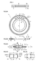
- Fig. 2A is a plan view showing Embodiment 2 of a thrust roller bearing according to the present invention.
- Fig. 2B is a cross-sectional view along the line IIB-IIB in Fig. 2A.
- Fig. 2C is an enlarged view of a main portion of Fig. 2B.
- Fig. 2D is an enlarged view of a main portion of another portion of Fig. 2A.
- Fig. 2E is an enlarged cross-sectional view along the line IIE-IIE in Fig. 2C.
- a thrust roller bearing 1 is constituted of a plurality of needle rollers 2 and two annular cages 3, 4 holding needle rollers 2 in a circumferential direction in a prescribed pitch.
- two cages 3, 4 have a plurality of pockets 5, 6 in a rectangular shape having a length larger than length L of needle roller 2 in a radial direction respectively.
- two cages 3, 4 are formed from a steel plate made of cold-rolled steel (SPCC) by press working. On opposing edges of each pocket 5, 6, roller holding portions 5a, 6a projecting so as to face each other are formed. Roller holding portions 5a, 6a hold needle roller 2 by sandwiching the same from above and below.
- SPCC cold-rolled steel
- length La of the roller holding portion is within a range of 30% to 80% of the pocket length.
- Needle roller 2 is formed by a needle roller 2a on the outer diameter side and a needle roller 2b on the inner diameter side, which are arranged in pockets 5, 6 in multiple rows.
- a difference in the peripheral speed of revolution between the outer diameter side portion and the inner diameter side portion is made smaller, thereby suppressing slipping with respect to the raceway surface (not shown).
- heating at a contact portion is reduced, and surface damage (smearing) can be prevented.
- the length in the radial direction of the roller holding portion is set to 30% to 80% of the length in the radial direction of the pocket. In this manner, while reliably holding the needle roller, oil passage performance can be improved.
- the lubricating oil can attain easy passage by virtue of concave portions 5b, 6b formed on an inner end side and an outer end side in the radial direction of roller holding portions 5a, 6a.
- needle roller 2 implemented by rollers 2a, 2b in multiple rows has been shown by way of example, the single-row needle roller may be employed.
- the end face of needle roller 2 may be in an arc face not limited to a flat shape.
- a radially outer portion of roller holding portion 5a of upper cage 3 is constituted of an inclined extension 3a bent from an outer end of roller holding portion 5a and an outer plate portion 3b bent so as to have a bend line intersecting the radial direction from the lower end of inclined extension 3a, as shown in Fig. 2C.
- a radially inner portion of roller holding portion 5a of upper cage 3 is constituted of an inclined extension 3c similarly bent from an inner end of roller holding portion 5a and an inner plate portion 3d bent so as to have a bend line intersecting the radial direction from the lower end of inclined extension 3c.
- a radially outer portion of roller holding portion 6a of lower cage 4 obtained by dying out with the same die as that for upper cage 3 is constituted of an inclined extension 4a bent from an outer end of roller holding portion 6a and an outer plate portion 4b bent so as to have a bend line intersecting the radial direction from the lower end of inclined extension 4a.
- a radially inner portion of roller holding portion 6a of lower cage 4 is constituted of an inclined extension 4c similarly bent from an inner end of roller holding portion 6a and an inner plate portion 4d bent so as to have a bend line intersecting the radial direction from the lower end of inclined extension 4c.
- Fig. 3 is a perspective view showing a state in which the needle roller is rotatably bound by the roller holding portion in the cage described above.
- Roller holding portion 5a is positioned above the axis of the needle roller, and projects toward the needle roller.
- Fig. 4 shows a roller row and a roller holding portion as well as a variation thereof in Embodiment 2 of the present invention.
- Fig. 4A shows a single roller holding portion in a single row roller. Length Lp in the radial direction of the pocket is slightly larger than roller length L.
- length La of roller holding portion 5a satisfies a relation with respect to length Lp in the radial direction of the pocket of 0.3Lp ⁇ La ⁇ 0.8Lp.
- a relation of 0.3Lp ⁇ La ⁇ 0.8Lp as shown in the inequality above is established between La and Lp.
- Fig. 4C shows an example in which a single roller holding portion is provided in multiple-row roller.
- Fig. 4D shows an example in which a plurality of roller holding portions are provided in multiple-row roller.
- La is set to be within a range of (0.3 to 0.8) ⁇ Lp.
- roller holding portions shown in Figs. 4A to 4D are all symmetric, asymmetric roller holding portions may be employed.
- thrust roller bearing 1 having the above-described structure attains clearance fit using caulked portion 8 of upper cage 3 as a guiding face so that needle roller 2 rolls between a raceway surface 9a of a first axis 9 (rotation axis) and a raceway surface 10a of a second axis (fixed axis) 10.
- first axis 9 rotates
- the roller rotates with first axis 9
- needle roller 2 rolls between first axis 9a and raceway surface 10a of second axis 10.
- the lubricating oil is supplied from a not-shown hydraulic pressure source via an oil path to thrust roller bearing 1.
- the lubricating oil passes the oil path as shown with an arrow a, and passes between raceway surface 10a of second axis 10 and a radially inner portion with respect to roller holding portion 6a of lower cage 4 as shown with an arrow b. Thereafter, the lubricating oil passes through a space around needle 2 and a space formed by cages 3, 4 as shown with an arrow c, and then lubricates between a side surface of needle roller 2 and roller holding portions 5a, 6a of cages 3, 4, between end faces of needle roller 2, as well as between the side surface of needle roller 2 and raceway surfaces 9a, 10a.
- the lubricating oil passes between raceway surface 10a of second axis 10 and a radially outer portion with respect to roller holding portion 6a of cage 4 and between raceway surface 9a of first axis 9 and a radially outer portion with respect to roller holding portion 5a of cage 3, and finally exits as shown with an arrow d.
- roller holding portions 5a, 6a formed by two cages 3, 4 thickness T1, T2 of the radially outer portion and the radially inner portion is made smaller than thickness T0 of roller holding portions 5a, 6a (see Fig. 2C).
- length La in the radial direction of the roller holding portion is set to be within a range of 0.3 to 0.8 of length Lp in the radial direction of the pocket (see Fig. 2D).
- a cross-section of a space between raceway surface 10a of second axis 10 and the radially inner portion with respect to roller holding portion 6a of lower cage 4 is made larger than in the conventional example, and not only flow-out performance but also flow-in performance of the lubricating oil is improved. Therefore, it is ensured that burn in each portion of the bearing can be prevented, and drilling abrasion of the end face of needle roller 2 and pockets 5, 6 of cages 3, 4 can be suppressed.
- the lubricating oil does not tend to stay, thereby suppressing an increase in the oil temperature. Accordingly, durability of the bearing can further be improved in addition to enhancement in the strength of the cage.
- a procedure for manufacturing thrust roller bearing 1 according to the present invention will now be described in detail.
- Two cages are worked by punching a window after forming, so that the roller holding portion has a length La attaining 30% to 80% of length Lp in the radial direction of the pocket.
- the steps of forming and punching the window may be performed in a single closed die forging step.
- the step of opening the window may be performed by electric discharge machining, wire cut working, or cutting.
- Two cages 3, 4 and needle roller 2 that has been or has not been subjected to quenching and tempering are set, and the outermost portion of outer plate portion 4b is bent upward, so as to form caulked portion 7.
- the innermost portion of inner plate portion 3d is bent downward to form caulked portion 8.
- Two cages 3, 4 are thus integrally fixed.
- an SUJ bearing steel which is category 1 or 2 of high carbon chromium bearing steel, for example, is used as a material of needle roller 2.
- carburization, quenching and tempering, or quenching and tempering after carbo-nitriding treatment is performed in a state in which needle roller 2 and two cages 3, 4 are set, so as to complete a product.
- conditions for carburizing treatment are as follows: carburization at 850°C ⁇ 35 minutes (in an atmosphere of the RX gas); quenching in an oil or a cooling gas; and subsequent tempering at 165°C ⁇ 60 minutes.
- conditions for the carbo-nitriding treatment are as follows: holding in an atmosphere for carbo-nitriding (adding 1 to 3 volume % of ammonia to the RX gas) at 840 to 850°C ⁇ 35 minutes for carbo-nitriding; and immediately thereafter, rapidly cooling in the oil or the cooling gas.
- two cages 3, 4 may be subjected to nitrocarburizing treatment in advance at 570 to 580°C ⁇ 35 minutes for improving strength.
- Needle roller 2 does not need to be subjected to heat treatment in advance. If heat treatment, that is, through hardening is performed in advance before incorporation, it is advantageous in that further improvement in strength can be achieved by carburization or the carbo-nitriding treatment which will be performed later, though a process step in manufacturing is increased.
- the process for manufacturing is at least simplified as compared with the conventional method in which two cages 3, 4 and needle roller 2 are separately subjected to heat treatment, and the caulked portion is annealed. If cages 3, 4 are nitrocarburized, it is possible to subject cages 3, 4 and needle roller 2 separately to heat treatment and to set the same, followed by caulking cages 3, 4.
- thrust roller bearing 1 By manufacturing thrust roller bearing 1 with the procedure describe above, specific properties described below can be obtained. Such properties will now be described in detail.
- a carburized case or a carbo-nitrided case is formed on its surface portion. Therefore, hardness of the surface is higher than in the conventional product. Even if bite of a foreign matter of high hardness takes place, an impression is unlikely to be produced, thereby contributing to long life.
- a nitrogen enriched layer is formed, and a residual amount of austenite therein is over 20 volume %.
- stress concentration has been observed around the impression. Such stress concentration, however, is mitigated by plastic deformation of the residual austenite which is present in a large amount, thereby contributing to further hardening and long life.
- the nitrogen enriched layer can be made to a thickness of not smaller than 0.1mm and to a surface hardness of not smaller than 750Hv.
- the inside hardness can be made as high as the surface hardness, thereby improving the strength of entire needle roller 2. Therefore, even under a harsh condition, for example, in a use under high load, needle roller 2 can bear such load sufficiently and satisfy a desired life.
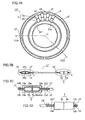
- Fig. 6A is a plan view showing Embodiment 3 of a thrust roller bearing according to the present invention.
- Fig. 6B is a cross-sectional view along the line VIB-O-VIB in Fig. 6A.
- Fig. 6C is a bottom view of Fig. 6A.
- Fig. 6D is an enlarged view of portion A in Fig. 6B.
- Fig. 6E is an enlarged view of portion B in Fig. 6B.
- Embodiment 3 is different from above-described Embodiment 2 only in a shape of the cage and the method of caulking. The same or corresponding components are given the same reference characters, and detailed description thereof will not be provided.
- a thrust roller bearing 11 is constituted of a plurality of needle rollers 2, and two annular cages 13, 14 holding needle rollers 2 in a circumferential direction in a prescribed pitch.
- a radially outer portion of a roller holding portion 15a of upper cage 13 is constituted of an inclined extension 13a bent from an outer end of roller holding portion 15a and an outer plate portion 13b bent toward the radial direction from the lower end of inclined extension 13a, as shown in Fig. 6D.
- a radially inner portion of roller holding portion 15a of upper cage 13 is constituted of an inclined extension 13c similarly bent from an inner end of roller holding portion 15a and an inner plate portion 13d bent toward the radial direction from the lower end of inclined extension 13c.
- a radially outer portion of a roller holding portion 16a of lower cage 14 obtained by dying out with the same die as that for upper cage 13 is constituted of an inclined extension 14a bent from an outer end of roller holding portion 16a and an outer plate portion 14b bent toward the radial direction from the lower end of inclined extension 14a.
- a radially inner portion of roller holding portion 16a of upper cage 14 is constituted of an inclined extension 14c similarly bent from an inner end of roller holding portion 16a and an inner plate portion 14d bent toward the radial direction from the lower end of inclined extension 14c.
- a portion 19 on an outer circumference of the cage serves as a positioning portion for bringing two cages 13, 14 in phase.
- a notch (not shown) is formed on an outer circumference of upper cage 13, to which a protrusion (not shown) formed on an outer circumference of lower cage 14 is engaged, whereby pitch of pockets 15, 16 of both cages 13, 14 is not displaced during caulking or the like.
- Partial caulked portions 17, 18 are formed at four places on the circumference with their phases shifted by 45° from each other, so as to prevent an influence on deformation of the cage during caulking.
- the partial caulked portion does not necessarily have to be formed at four places. If the partial caulked portions are evenly distributed at two or more places, they can prevent an influence on deformation of the cage during caulking. For example, they may be arranged in 5 to 8 places.
- length La of the roller holding portion is set to be within a range of 30% to 80% of the pocket length Lp.
- the roller holding portion it is more preferable for the roller holding portion to have a length not smaller than 40% of the length in the radial direction of the pocket.
- the roller holding portion it is more preferable for the roller holding portion to have a length not larger than 70% of the length in the radial direction of the pocket. In the embodiments described later, it has been confirmed that holding of the needle roller and the oil passage performance are both satisfied if the length of the roller holding portion is within a range of 30% to 80% of the length in the radial direction of the pocket.
- Fig. 7A is a plan view showing Embodiment 4 of a thrust roller bearing according to the present invention.
- Fig. 7B is a cross-sectional view along the line VIIB-O-VIIB in Fig. 7A.
- Fig. 7C is an enlarged view of portion C of Fig. 7B.
- Fig. 7D is an enlarged view of portion D in Fig. 7B.
- Embodiment 4 is different from above-described Embodiment 3 only in a direction of caulking. The same or corresponding components are given the same reference characters, and detailed description thereof will not be provided.
- a thrust roller bearing 11' is constituted of a plurality of needle rollers 2, and two annular cages 13', 14' holding needle rollers 2 in a circumferential direction in a prescribed pitch.
- a radially outer portion of roller holding portion 15a of upper cage 13' is constituted of inclined extension 13a bent from an outer end of roller holding portion 15a and outer plate portion 13b bent so as to have a bend line intersecting the radial direction from the lower end of inclined extension 13a, as shown in Fig. 7C.
- a radially inner portion of roller holding portion 15a of upper cage 13 is constituted of inclined extension 13c similarly bent from an inner end of roller holding portion 15a and an inner plate portion 13d' bent toward the radial direction from the lower end of inclined extension 13c.
- a radially outer portion of roller holding portion 16a of lower cage 14 is constituted of inclined extension 14a bent from an outer end of roller holding portion 16a and outer plate portion 14b bent toward the radial direction from the lower end of inclined extension 14a.
- a radially inner portion of roller holding portion 16a of upper cage 14 is constituted of inclined extension 14c similarly bent from an inner end of roller holding portion 16a and an inner plate portion 14d' bent toward the radial direction from the lower end of inclined extension 14c.
- length La of the roller holding portion is within a range of 30% to 80% of the pocket length Lp.
- Fig. 8A is a plan view showing Embodiment 5 of a thrust roller bearing according to the present invention.
- Fig. 8B is a cross-sectional view along the line VIIIB-O-VIIIB in Fig. 8A.
- Fig. 8C is an enlarged view of portion E in Fig. 8B.
- Embodiment 5 is different from above-described Embodiments 2 to 4 only in means for fixing two cages. The same or corresponding components are given the same reference characters, and detailed description thereof will not be provided.
- a thrust roller bearing 21 is constituted of a plurality of needle rollers 2, and two annular cages 23, 24 holding needle rollers 2 in a circumferential direction in a prescribed pitch.
- a radially outer portion of a roller holding portion 25a of upper cage 23 is constituted of an inclined extension 23a bent from an outer end of roller holding portion 25a and an outer plate portion bent so as to have a bend line intersecting the radial direction from the lower end of inclined extension 23a, as shown in Fig. 8C.
- a radially inner portion of roller holding portion 25a of upper cage 23 is constituted of an inclined extension 23c similarly bent from an inner end of roller holding portion 25a and an inner plate portion 23d bent so as to have a bend line intersecting the radial direction from the lower end of inclined extension 23c.
- a radially outer portion of a roller holding portion 26a of lower cage 24 is constituted of an inclined extension 24a bent from an outer end of roller holding portion 26a and an outer plate portion 24b bent toward the radial direction from the lower end of inclined extension 24a.
- a radially inner portion of roller holding portion 26a of lower cage 24 is constituted of an inclined extension 24c similarly bent from an inner end of roller holding portion 26a and an inner plate portion 24d bent so as to have a bend line intersecting the radial direction from the lower end of inclined extension 24c.
- two cages 23, 24 are integrally fixed in the inner circumferential portion and the outer circumferential portion respectively with spot welding portions 27, 28, as shown in Fig. 8A. These welding portions 27, 28 are provided at four places in a circumferential direction at regular intervals with their phases shifted by 45° from each other, thereby preventing an influence on deformation of the cage by welding.
- the partial caulked portions do not necessarily have to be formed at four places. If the partial caulked portions are evenly distributed at two or more places, influence on deformation of the cage during caulking can be prevented.
- a portion 29 on an outer circumference of the cage serves as a positioning portion for bringing two cages 23, 24 in phase.
- a notch 29b formed on an outer circumference of lower cage 24 is engaged to a protrusion 29a formed on an outer circumference of upper cage 23, whereby pockets 25, 26 of two cages 23, 24 are not brought out of phase.
- the structure of positioning portion 29 is not limited to such an example.
- a staking mechanism in which a part of the outer circumference portion of lower cage 24 is caulked for engagement to upper cage 23 for fixation, or an engagement mechanism using a pin and a hole may be employed.
- length La of the roller holding portion is within a range of 30% to 80% of the pocket length Lp.
- a single roller holding portion for multiple roller rows was provided in the thrust roller bearing shown in Figs. 2A to 2E.
- This structure is similar not only to those in Figs. 2A to 2E but also to that in Fig. 4C.
- a thrust roller bearing having a cage with such a structure was assembled.
- a variety of lengths La in the radial direction of the roller holding portion were set, so as to (A1) evaluate a tendency of falling of the roller from the pocket through a drop test with respect to three thrust roller bearings.
- a bearing to be tested was allowed to fall freely from a prescribed height (1.5m) down to a concrete ground, so as to verify falling of the roller.
- the bearing was imposed with light load of approximately 100N and rotated at 1000 to 3000 r/min; 500ml of oil was supplied from the radially inner side; and a time period until the oil is completely drained from an outlet on the radially outer side was measured.
- a cage with multiple roller rows shown in Fig. 14B was used as a comparison example. Table 1 shows a result of the drop test, while Table 2 shows a result of the oil passage performance test.
- the thrust roller bearing in Embodiment 1 of the present invention has a shape similar to that of the thrust roller bearing shown in Fig. 1.
- a hardened case in a surface portion, in particular in an end face of a pocket is formed to a depth larger than 3 ⁇ m and smaller than 100 ⁇ m. Therefore, abnormal abrasion such as drilling abrasion will be unlikely particularly in a peripheral portion of a window of the pocket where an outer circumferential side portion of the roller tends to contact.
- an embrittled layer is thin. Accordingly, a crack is unlikely even in caulking an end portion on the outer or inner circumferential side of the cage. A crack is unlikely not only during such working but also during use.
- the hardened case described above can be obtained in a short period of time with the nitrocarburizing treatment, for example.
- the thrust roller bearing in Embodiment 7 of the present invention has a shape similar to that of the thrust roller bearing shown in Figs. 2A to 2E.
- the most significant feature in the present embodiment different from Embodiment 2 is that the hardened case is formed to a depth in a range larger than 3 ⁇ m and smaller than 100 ⁇ m in a surface portion of the cage, in particular in a peripheral portion of the window of the pocket. Therefore, abnormal abrasion does not occur in the peripheral portion of the window of the cage by the radially outer side end portion of the needle roller.
- cages 3, 4 may be drawn and formed from band steel such as SCM 415 by pressing.
- Fig. 3 shown above is a perspective view showing a state in which the needle roller is rotatably bound by the roller holding portion in the cage.
- Roller holding portion 5a is positioned above the axis of the needle roller, and projects toward the needle roller.
- needle roller 2b is strongly pressed against the edge of the window of the pocket. Without any measure against it, drilling abrasion is caused in the periphery of the window.
- the oil passage performance in the thrust roller bearing in the present embodiment is the same as in Embodiment 2.
- a cage is formed by an upper member described above, that is, upper cage 3, and a lower member, that is, lower cage 4.
- a thin steel plate of a prescribed material is machined, and a pocket including an opening serving as a window is formed.
- "Machining” here includes antiplane extrusion press working for forming a pocket or punching for forming an opening as described above.
- two cages 3, 4, that is, the upper member and the lower member are subjected to the nitrocarburizing treatment at 570 to 580°C ⁇ 35 minutes for enhancing the strength.
- Other hardening treatment may be employed.
- the roller is subjected to a prescribed hardening treatment. Normally, it is subjected to quenching and tempering treatment. Alternatively, it may be subjected to the quenching treatment or the quenching and tempering treatment after the carbo-nitriding treatment.
- An SUJ bearing steel which is category 1 or 2 of high carbon chromium bearing steel, for example, is used as a material of needle roller 2, which is subjected to oil-hardening at 840°C ⁇ 30 minutes and subsequent tempering at 180°C ⁇ 90 minutes, so that the surface hardness is set approximately to Vickers hardness (Hv) of 700 to 750. Needle roller 2 does not have to be subjected to heat treatment in advance. If heat treatment, that is, through hardening is performed in advance before incorporation, a process step in manufacturing is increased.
- the roller is set so as to be accommodated in the pocket of the cage. Then, in at least one of the radially outer side end portion and the radially inner side end portion of the cage, the upper member and the lower member are superposed and bent, and subjected to caulking.
- the process for manufacturing is simplified as compared with the conventional method in which two cages 3, 4 and needle roller 2 are separately subjected to heat treatment, and the caulked portion is annealed.
- the quenching treatment after carburizing treatment or the quenching and tempering treatment after carbo-nitriding treatment may be performed after caulking described above.
- a carburized case or a carbo-nitrided case is formed in the surface portion of needle roller 2, hardness in the surface is higher than in the conventional product. Therefore, even if bite of a foreign matter of high hardness takes place, an impression is unlikely to be produced, thereby contributing to long life.
- the carbo-nitriding treatment a nitrogen enriched layer is formed, and a residual amount of austenite therein is over 20 volume %.
- the nitrogen enriched layer can be made to a thickness of not smaller than 0.1mm and to a surface hardness of not smaller than 750Hv.
- the inside hardness can be made as high as the surface hardness, thereby improving the strength of entire needle roller 2. Therefore, even under a harsh condition, for example, in a use under high load condition, needle roller 2 can bear such load sufficiently and satisfy a desired life.
- the thrust roller bearing in Embodiment 3 of the present invention has a shape similar to that of the thrust roller bearing shown in Figs. 6A to 6E in Embodiment 3 described above.
- the hardened case is formed to a depth in a range larger than 3 ⁇ m and smaller than 100 ⁇ m in a surface portion of the cage, in particular in a peripheral portion of the window of the pocket. Therefore, abnormal abrasion does not occur in the peripheral portion of the window of the cage by the radially outer side end portion of the needle roller. In addition, a crack will not be produced even if a caulking process in which superposition and bending is performed in the end portions on the radially outer side and the radially inner side of the cage is performed with the hardened case present.
- cages 3, 4 may be drawn and formed from band steel such as SCM 415 other than SPCC by pressing.
- the thrust roller bearing in Embodiment 9 of the present invention has a shape similar to that of the thrust roller bearing shown in Figs. 7A to 7D in Embodiment 4 described above.
- the hardened case is formed to a depth in a range larger than 3 ⁇ m and smaller than 100 ⁇ m in a surface portion of the cage, in particular in a peripheral portion of a window of a pocket. Therefore, abnormal abrasion does not occur in the peripheral portion of the window of the cage by the radially outer side end portion of the needle roller. In addition, a crack will not be produced even if a caulking process in which superposition and bending is performed in the end portions on the radially outer side and the radially inner side of the cage is performed with the hardened case present. In order to further ensure prevention of abrasion and not to produce a crack during caulking, it is more preferable to set the depth of the hardened case to be within a range of 5 ⁇ m and 50 ⁇ m.
- the thrust roller bearing in Embodiment 10 of the present invention has a shape similar to that of the thrust roller bearing shown in Figs. 8A to 8C in Embodiment 4 described above.
- the hardened case is formed to a depth in a range larger than 3 ⁇ m and smaller than 100 ⁇ m in a surface portion of the cage, in particular in a peripheral portion of the window of the pocket. Therefore, abnormal abrasion does not occur in the peripheral portion of the window of the cage by the radially outer side end portion of the needle roller. In addition, a crack will not be produced even if a caulking process in which superposition and bending is performed in the end portions on the radially outer side and the radially inner side of the cage is performed with the hardened case present. In order to further ensure prevention of abrasion and not to produce a crack during caulking, it is more preferable to set the depth of the hardened case to be within a range of 5 ⁇ m and 50 ⁇ m.
- Abrasion depth was obtained by measuring an abrasion shape on the surface from the end portion with a shape measurement apparatus (a contracer).
- Fig. 10A shows a result of measurement with the contracer when the case depth was set to 5 ⁇ m (an example of the present invention), while Fig. 10B shows a result of measurement when the case depth was set to 3 ⁇ m (a comparison example).
- the abrasion depth indicating a drop from the end portion where abrasion was not caused was approximately 5 ⁇ m, which is within a tolerance.
- the abrasion depth was as large as 23 ⁇ m when the case depth was set to 3 ⁇ m as shown in Fig. 10B. If such abnormally deep abrasion takes place, smooth rotation of the needle roller is hindered and durability is considerably deteriorated. Therefore, in order to ensure sufficient resistance to abrasion, the hardened case should be formed to a depth larger than 3 ⁇ m.
- Objects to be tested in which the case depth was varied through the nitrocarburizing treatment onto a thin steel plate material were prepared. Two types of objects to be tested having the case depth of 100 ⁇ m and 90 ⁇ m respectively were fabricated with the nitrocarburizing treatment. Then, two thin steel plates provided with the hardened case (nitrocarburized case) were superposed, bent, and subjected to caulking. Thereafter, presence/absence of a crack was examined. Here, an inner dend radius R in bending was set to 0.2.
- Figs. 11A and 11B show a result. Referring to these figures, a crack was not observed in the worked portion when the case depth was set to 90 ⁇ m. On the other hand, a crack was produced when the case depth was set to 100 ⁇ m, which indicates that deterioration in durability is inevitable.
- case depth nitrogencarburized case
- a thrust roller bearing satisfying both resistance to abrasion and resistance to caulking crack tendency can be provided.
- the thrust roller bearing in Embodiment 11 of the present invention has a shape similar to that of the thrust roller bearing shown in Figs. 2A to 2E in Embodiment 2 and Fig. 3 described above.
- Needle roller 2 is constituted of needle roller 2a on the radially outer side and needle roller 2b on the radially inner side, and arranged in multiple rows in pockets 5, 6.
- a difference in a peripheral speed of revolution between the radially outer side portion and the radially inner side portion is made smaller, thereby suppressing slipping with respect to a raceway surface (not shown). Accordingly, heating at a contact portion is reduced, and surface damage or surface-originating separation can be prevented.
- multiple-row needle rollers 2a, 2b have the same length, depending on a condition of use, selection between the outer diameter shorter than the inner diameter and the outer diameter longer than the inner diameter can be made. For example, load-carrying capacity may be improved by setting the length of either longer one out of the outer diameter or the inner diameter to a length 1.2 times the shorter one.
- length La in the radial direction of roller holding portions 5a, 6a is formed to be smaller than roller length L.
- the lubricating oil can attain easy passage by virtue of concave portions 5b, 6b formed on both ends of roller holding portions 5a, 6a.
- the end face of needle rollers 2a, 2b is not limited to a flat shape but may be formed by an arc face.
- a corner portion of roller holding portions 5a, 6a is formed in a rolled-over manner when pockets 5, 6 are punched by pressing.
- the corner portion is smoothly rolled over by surface press working of an inner edge portion after punching.
- Needle rollers 2a, 2b can be guided and held in a stable manner without interrupting a lubricating oil film formed on the surface of needle rollers 2a, 2b.
- end face 5c, 6c of each of needle rollers 2a, 2b is an F end face as shown in Fig. 12, and the end face accuracy is set to not larger than 30 ⁇ m.
- the F end face refers to a shape according to F (flat) defined by JIS (Japanese Industrial Standards).
- Fig. 13A is a schematic diagram showing a method of measuring the end face accuracy.
- variation in height in end faces 5c, 6c of needle roller 2 is measured. This measurement is performed along a direction of a diameter of end faces 5c, 6c respectively as shown with an arrow in the figure, and performed once for each end face so that measurement directions are at a right angle with respect to each other.
- a maximum value (Hmax) and a minimum value (Hmin) of the height in roller end faces 5c, 6c are extracted from variation in height measured in such a manner shown in Fig. 13B, and a difference between Hmax and Hmin indicates the end face accuracy.
- Talysurf manufactured by Taylor Hobson Ltd.
- the inventors of the subject application presume that the problems of drilling abrasion and large bearing noise in the conventional thrust roller bearing are caused by the following factors. That is, the end face accuracy in each of needle rollers 2a, 2b used in thrust roller bearing 1 is so large as to increase resistance in a contact portion of needle roller 2a with adjacent needle roller 2b and cages 3, 4. Accordingly, friction when these elements collide with each other causes drilling abrasion, and the sound produced by friction when these elements collide with each other increases the bearing noise. Then, a relation between the end face accuracy of needle rollers 2a, 2b and the bearing noise in thrust roller bearing 1 was examined.
- Fig. 14 is a diagram (graph) showing a relation between the end face accuracy of needle rollers 2a, 2b and the bearing noise in the thrust roller bearing. Measurement of the noise was performed under the conditions in the following. Revolution speed of the thrust roller bearing was set to 1800rpm; load was set to 100N; and a position of microphone was set distanced from the thrust roller bearing by 100mm in a direction at an angle of 45 degrees with respect to the normal of the main surface of the cage.
- the bearing noise was larger than 81dBA when the end face accuracy of the needle roller was equal to or larger than 50 ⁇ m, whereas it was significantly lowered to 78dBA or smaller when the end face accuracy was equal to or smaller than 30 ⁇ m. This is because frictional resistance between the needle roller and the adjacent needle roller as well as frictional resistance between the needle roller and the cage were significantly reduced when the end face accuracy of the needle roller is equal to or smaller than 30 ⁇ m. Therefore, when the end face accuracy of the needle roller is equal to or smaller than 30 ⁇ m, frictional resistance is significantly lowered, and drilling abrasion will also be unlikely.
- the end face accuracy of each of needle rollers 2a, 2b is set to not larger than 30 ⁇ m. Accordingly, frictional resistance between needle roller 2a and adjacent needle roller 2b as well as frictional resistance between needle rollers 2a, 2b and cages 3, 4 are made smaller. Consequently, drilling abrasion due to friction when these elements collide with each other is in particular unlikely, and the bearing noise produced by the sound when these elements collide with each other is in particular lowered.
- needle rollers 2a, 2b are formed by common outer diameter grinding, followed by secondary working on the end face by grinding or wire cut discharge machining.
- wire cut discharge refers to a machining method of cutting a material using a conductive wire with a small diameter as an electrode. In this manner, the end face accuracy of needle rollers 2a, 2b is set to not larger than 30 ⁇ m.
- Two cages 3, 4 and needle roller 2 that has been or has not been subjected to quenching and tempering are set, and the outermost portion of outer plate portion 4b is bent upward, so as to form caulked portion 7.
- the innermost portion of inner plate portion 3d is bent downward, to form caulked portion 8.
- Two cages 3, 4 are thus integrally fixed.
- an SUJ bearing steel which is category 1 or 2 of high carbon chromium bearing steel, for example, is used as a material of needle roller 2. Needle roller 2 is subjected to oil-hardening at 840°C ⁇ 30 minutes and subsequent tempering at 180°C ⁇ 90 minutes, so that the surface hardness is set approximately to Vickers hardness (Hv) of 700 to 750.
- needle roller 2 and two cages 3, 4 are held in a carbo-nitriding atmosphere (adding 1 to 3 volume % of ammonia to the RX gas) at 840 to 850°C ⁇ 35 minutes for carbo-nitriding, and immediately thereafter, rapidly cooled in the oil.
- two cages 3, 4 may be subjected to nitrocarburizing treatment in advance at 570 to 580°C ⁇ 35 minutes for improving strength.
- Needle roller 2 does not need to be subjected to heat treatment in advance. If needle roller 2 is subjected to heat treatment, that is, through hardening in advance before incorporation, further improvement in strength thereof can be achieved by carburization or the carbo-nitriding treatment performed later, though a process step in manufacturing is increased.
- the process for manufacturing is simplified as compared with the conventional method in which at least two cages 3, 4 and needle roller 2 are separately subjected to heat treatment, and the caulked portion is annealed.
- thrust roller bearing 1 By manufacturing thrust roller bearing 1 with the procedure described above, specific properties described below can be provided. Such properties will now be described in detail.
- a carburized case or a carbo-nitrided case is formed in its surface portion. Therefore, hardness of the surface is higher than in the conventional product. Even if bite of a foreign matter of high hardness takes place, an impression is unlikely to be produced, thereby contributing to long life.
- a nitrogen enriched layer is formed in needle roller 2, and a residual amount of austenite therein is over 20 volume %. Conventionally, if bite of a foreign matter of high hardness occurs in raceway surfaces 9a, 10a, stress concentration has been observed around the impression.
- the nitrogen enriched layer can be made to a thickness of not smaller than 0.1mm and to a surface hardness of not smaller than 750Hv.
- the inside hardness can be made as high as the surface hardness, thereby improving the strength of entire needle roller 2. Therefore, needle roller 2 can be used even under a harsh condition, for example, in a use under high load condition, and can satisfy a desired life.
- the thrust roller bearing in Embodiment 12 of the present invention has a shape similar to that of the thrust roller bearing shown in Figs. 6A to 6E in Embodiment 3 described above.
- the most significant feature in the present embodiment is that the end faces of a plurality of rollers are F end faces, and the end face accuracy is set to not larger than 30 ⁇ m. With this end face, drilling abrasion can be suppressed and the bearing noise can be made smaller.
- the thrust roller bearing in Embodiment 13 of the present invention has a shape similar to that of the thrust roller bearing shown in Figs. 7A to 7D in Embodiment 4 described above.
- the end faces of a plurality of rollers are F end faces, and the end face accuracy is set to not larger than 30 ⁇ m. With this end face, drilling abrasion can be suppressed and the bearing noise can be made smaller.
- the thrust roller bearing in Embodiment 14 of the present invention has a shape similar to that of the thrust roller bearing shown in Figs. 8A to 8C in Embodiment 5 described above.
- the present invention is applicable to a thrust roller bearing using a long cylindrical roller or a cylindrical roller.
- the present embodiment has shown an example in which the rollers are arranged in multiple rows, an example in which the rollers are arranged in a single row as shown in Fig. 16A can achieve an effect similar to that in embodiments described above, so long as the end face of each of the plurality of rollers is an F end face and the end face accuracy is not larger than 30 ⁇ m.
- grinding or wire cut discharge machining has been shown as an example of a method of secondary working of the end face of the roller, any working method which can attain the end face accuracy of not larger than 30 ⁇ m may be employed.
Landscapes
- Engineering & Computer Science (AREA)
- General Engineering & Computer Science (AREA)
- Mechanical Engineering (AREA)
- Rolling Contact Bearings (AREA)
Abstract
Description
- The present invention relates to a thrust roller bearing used in an automatic transmission and a compressor in an automobile, as well as to a cage used therein.
- A thrust roller bearing is constituted of a needle roller, a cage and a roller bearing ring, and has such a structure that the needle roller and the roller bearing ring are in line contact. Accordingly, high load-carrying capacity and high rigidity can be obtained for a small bearing projected area. As such, the thrust roller bearing is suitable as a bearing used in a harsh condition of use, such as poor lubrication or high-speed rotation, and widely used as a bearing for an automatic transmission or a bearing for a compressor of an air-conditioner in an automobile, for example.
- Fig. 15A shows a roller holding portion provided in a pocket for accommodating a conventional needle roller. Fig. 15A shows a single-row roller, while Fig. 15B shows a multiple-row roller. Referring to these figures, in a cage, a
pocket 105 accommodatingneedle rollers roller holding portion 105a is provided on a periphery of a window in parallel to a central axis of the pocket, and projects toward the needle roller side above the needle roller axis. Here,roller holding portion 105a is provided on an entire periphery of the window in parallel to the axis. In such an arrangement of the roller holding portion, opening area, that is, a gap is inevitably small, and performance of oil passage to the inside of the cage is not sufficient. - As such, in order to increase an amount of passage of a lubricating oil per unit time, a thrust roller bearing as shown in Figs. 16A to 16C has been proposed (Japanese Patent Laying-Open No. 2002-70872). In Figs. 16A to 16C, a thrust roller bearing 50 includes a
needle roller 80 and twoannular cages cages window 61 of the upper cage and awindow 71 of the lower cage respectively. Here, windows have a length larger than the roller length in a radial direction respectively.
Roller holding portions needle rollers 80. In twocages roller holding portions roller length 1. In addition, at least one of twocages - In this manner, a gap is enlarged in at least one of the radially outer portion and the radially inner portion having a thickness smaller than the roller holding portion. Accordingly, flow-in performance or flow-out performance of the lubricating oil passing through the gap is improved, and an amount of lubricating oil passing through the bearing per unit time can be increased. In addition, blocking by the cage of passage of the lubricating oil does not tend to occur, and stay of the lubricating oil is prevented. Consequently, temperature increase in the oil can be suppressed, thereby improving durability of the bearing. In the example above, in two
cages outer plate portions innermost portions inner plate portions innermost portion 67 ofinner plate portion 63 is caulked. In this manner, twocages - Though not limited to the thrust roller bearing, falling of a needle roller must not occur in particular in the thrust roller bearing under a condition of use in which the thrust roller bearing is operated under high load and in high speed. If the length of the roller holding portion is made smaller in the above-described thrust roller bearing, however, it will be difficult to hold the needle roller in a stable manner and falling of the needle roller from the cage may take place, though probability is low. In other words, improvement in the amount of oil passage of the lubricating oil results in a possibility of occurrence of falling of the needle roller, though probability is low. Hence, development of a thrust roller bearing free from falling of a needle roller while securing the oil passage performance of the lubricating oil has been demanded.
- In addition, in the thrust roller bearing described above, the roller is pressed against the outer diameter side by centrifugal force during rotation. Therefore, unless an end face on the radially outer side of the pocket of the cage has a hardness and a case depth higher than a prescribed level, abrasion may occur, which will lead to breakage. Though it is possible to form a hardened case in the cage with heat treatment such as quenching, deformation by heat may occur due to quenching or the like. Accordingly, in order to prevent deformation of the cage due to heat treatment, prevention of deformation due to heat treatment by forming a corrugated portion in a cage has been proposed (Japanese Patent Laying-Open No. 2000-097242).
- Even with the cage having a shape for preventing deformation due to heat treatment described above, however, if the case depth is too large, the cage tends to be embrittled, and a crack or the like may be produced during working or in use, resulting in breakage. In particular, in order to increase the thickness of the hardened case from a worked face, a time period for treatment should be extended, leading to cost increase. Therefore, development of a thrust roller bearing having a cage capable of overcoming the above-described problems as well as such a cage has been desired.
- Moreover, in the conventional thrust roller bearing, an end face of the roller is pressed against the wall surface of the window by the centrifugal force. Furthermore, because of the contact caused by rotation of the needle roller, abnormal abrasion (hereinafter, referred to as "drilling abrasion") is caused in the window. In addition, bearing noise has been large. As the thrust needle bearing is mainly used in an automobile, in recent days when quietness within a car is demanded, lowering of the bearing noise in the thrust roller bearing has also been demanded.
- An object of the present invention is to provide a thrust roller bearing having improved oil passage performance of a lubricating oil in the inside of a bearing while holding a needle roller in a stable manner, as well as a cage.
- According to a thrust roller bearing of the present invention different from the thrust roller bearing of the invention above, a cage having a hardened case so as not to cause a crack during working and in use, while suppressing abrasion and attaining a short time period for treatment, as well as a thrust roller bearing incorporating the cage are provided.
- According to a thrust roller bearing of the present invention different from the two thrust roller bearings in the invention above, a thrust roller bearing unlikely to suffer from drilling abrasion and attaining lower bearing noise is provided.
- The above-described thrust roller bearings are in common in higher durability, and the object of each thrust roller bearing is summarized as improvement in durability. The thrust roller bearing and the cage according to the present invention do not necessarily satisfy all of the three individual objects, but should only satisfy any one of those three objects. It goes without saying that two or more of the three objects above may be satisfied.
- A thrust roller bearing according to the present invention includes a needle roller, a cage holding the needle roller in a pocket for accommodating the needle roller, and a pair of roller bearing rings in contact with the needle roller so as to sandwich the needle roller and the cage. A roller holding portion provided in the pocket has a length within a range of 30% to 80% of a length in a radial direction of the pocket.
- With such a structure, while attaining a function to hold the needle roller, oil passage performance to the inside of the bearing can be improved and the life of the bearing can be extended. If the roller holding portion has the length less than 30% of the length in the radial direction of the pocket, it is difficult to hold the needle roller in a stable manner. On the other hand, if the roller holding portion has the length more than 80% of the length in the radial direction of the pocket, passage of the lubricating oil is blocked and the oil passage performance is deteriorated. Therefore, long-time use will cause temperature increase in the lubricating oil, resulting in deterioration in durability of the thrust roller bearing. From the viewpoint of ensured holding of the needle roller, it is more preferable for the roller holding portion to have a length not smaller than 40% of the length in the radial direction of the pocket. From the viewpoint of improvement in the oil passage performance, it is more preferable for the roller holding portion to have a length not larger than 70% of the length in the radial direction of the pocket.
- Though the roller holding portion described above is usually formed in a symmetrical manner, it may be formed asymmetrically. In other words, a shape of the roller holding portion formed on a right periphery and a shape of the roller holding portion formed on a left periphery of the window of the pocket may not be symmetrical with respect to the central axis of the window of the pocket. In this case, with regard to the roller holding portions on both sides, a length of one roller holding portion having a smaller length in the radial direction (if the roller holding portion is divided into a plurality of sections, one having smaller total length) is set to be not smaller than 30% of the length in the radial direction of the pocket, and a length of the other roller holding portion having a larger length in the radial direction (if the roller holding portion is divided into a plurality of sections, one having larger total length) is set to be not larger than 80% of the length in the radial direction of the pocket. That is, 0.3 × (length in the radial direction of the pocket: Lp) ≤ Min (roller holding portion (right side), roller holding portion (left side)), and Max (roller holding portion (right side), roller holding portion (left side)) ≤ 0.8 × Lp.
- The roller holding portion described above is constituted of a plurality of roller holding portions. The roller holding portion may be structured so that the total length of the plurality of roller holding portions is within a range of 30% to 80% of the length in the radial direction of the pocket.
- By implementing the roller holding portion with the plurality of roller holding portions separate from each other, between two opposing factors of holding the roller and securing the oil passage performance, for example, the oil passage performance can be maximized on a presumption that minimum holding of the roller is attained in view of practical use.
The plurality of roller holding portions may be adapted to a multiple-row roller for example, or alternatively, they may be adapted to a single-row roller. In addition, by implementing an arrangement of the plurality of roller holding portions, in addition to improving the oil passage performance, the roller can be held and guided over a larger length. Thus, stable rotation can be achieved. - The needle roller described above may be constituted of multiple roller rows, and a roller holding portion having a length smaller than that of the needle roller may be provided in respective one of multiple roller rows.
- With such a structure, in an example of a multiple-row roller, an arrangement of the roller holding portion in which minimum holding of the roller in each row of the multiple rows is satisfied, and oil passage performance of the lubricating oil to the roller in each row of the multiple rows is maximized, can be achieved.
- The needle roller may be constituted of multiple roller rows, and the multiple-row needle roller may be held by one common roller holding portion. With such a structure, a process for forming the roller holding portion is simplified.
- Another thrust roller bearing according to the present invention includes a plurality of rollers, and a cage made of metal and holding the roller so as to sandwich the same with an upper member (upper cage) and a lower member (lower cage). A nitrocarburized case is formed to a depth in a range larger than 3µm and smaller than 100µm in a surface of the cage.
- With such a structure, the depth of the nitrocarburized case of the cage is set to be within a prescribed range. Thus, while abnormal abrasion in the cage during use is suppressed, occurrence of a crack in a caulked portion in a process of manufacturing and assembling the thrust roller bearing can be avoided. If the depth of the nitrocarburized case in the surface portion is equal to or less than 3µm, the abnormal abrasion described above cannot be avoided. On the other hand, if the depth of the nitrocarburized case in the surface portion is equal to or larger than 100µm, a crack may be produced in the caulked portion in caulking during assembly of the cage. More desirably, the depth of the nitrocarburized case is in a range of not smaller than 5µm and not larger than 50µm.
- The depth of the nitrocarburized case described above may be (A1) a depth of a degraded layer observed with an optical microscope after polishing and lightly etching the profile section. Alternatively, the depth of the nitrocarburized case may be (A2) a distance from the surface in a position having a hardness substantially equal to the inside hardness, which hardness is measured in a prescribed pitch, for example, a pitch of 0.5µm, from the surface. The depth of the nitrocarburized case found by using at least one of the measurement methods of (A1) and (A2) should only be within the range described above. It is to be noted that the nitrocarburized case described above is also formed on the surface of a thin steel plate material, or on an end surface formed by providing an opening in the thin steel plate.
- The nitrocarburized case described above may be replaced by any surface hardening treatment described below. Alternatively, it may be replaced with a hardened case replaced by a hardening treatment other than the treatment described below. The hardened case is formed not only on a flat surface of the thin plate material but also on an end face formed by providing a window in the cage (section profile of a thickness of the thin plate material).
- Yet another thrust roller bearing according to the present invention includes a roller, and a cage holding the roller so as to sandwich the same with an upper member (upper cage) and a lower member (lower cage). In the cage, a nitrocarburized case is formed to a depth in a range larger than 3µm and smaller than 100µm in its surface. The upper member and the lower member are superposed and bent in at least one of a radially outer end portion and a radially inner end portion thereof, and subjected to caulking. The nitrocarburized case plastically deforms in the caulked portion.
- With such a structure, after the upper member and the lower member of the cage are subjected to press working for providing a pocket and for opening a window in the pocket for example, the upper member and the lower member are subjected to nitrocarburizing treatment, to form a hardened case on the surface. After the nitrocarburized case is formed, the roller is set in the pocket. Then, the upper member and the lower member can be superposed and bent, and subjected to caulking. In the process described above, for example, it is not necessary to subject the superposed and bent portion to softening or the like, thereby simplifying the manufacturing process. The process can thus be simplified because the upper member and the lower member can be subjected to caulking with the nitrocarburized case present, which resulted from the fact that a depth of the nitrocarburized case has been set to be smaller than 100µm.
- The fact that the nitrocarburized case has been bent can be verified by observation with naked eyes or an optical microscope after polishing and lightly etching that portion. It is possible to observe that the nitrocarburized case has plastically deformed.
- The nitrocarburized case described above can be formed in a following manner. In the nitrocarburizing treatment, nitriding with low surface nitrogen concentration is performed with such a method as: (a1) a method of immersing a cage into molten salt having lowered nitriding capability, which molten salt is NaCNO obtained by blowing air into NaCN in advance; or (a2) a method of carbo-nitriding in an atmosphere obtained by adding ammonia (NH3) to carburization gas. Whereas the surface hardness attains to approximately Hv 1200 in a case of normal nitriding, the hardness of the nitrocarburized case is not as high as that. In spite of this fact, compressive stress remains on the surface, and fatigue strength is improved.
- The nitrocarburized case described above can be replaced by a hardened case hardened with a different method. For example, it may be replaced with a hardened case formed by heat treatment including quenching treatment. By setting the percentage of content of an alloying element such as carbon, silicon or manganese to be within an appropriate range in a composition of steel, a prescribed quench hardening capability is ensured, and a quench hardened structure of martensite or bainite can be formed on the surface portion. Such a structure may be quenched by heating only the surface portion with high-frequency heating or laser heating, or may be quenched by uniform heating of the entire body. After such quenching, tempering may or may not be applied.
- The nitrocarburized case described above may be replaced with a hardened case formed by at least one treatment of carburization treatment, carbo-nitriding treatment, ion nitriding treatment, quenching treatment, and working treatment.
- The method of carburization treatment described above includes pack carburizing, liquid carburizing, and gas carburizing. For example, gas carburizing is performed in the following manner. Air is mixed with methane (CH4), ethane (C2H5), propane (C3H8) or the like, which is in turn decomposed using Ni catalyst, resulting in production of H2O. Thus produced H2O is then removed so as to obtain an endothermic gas (also referred to as an "end gas" or an "RX gas") having a composition of approximately 20% of CO, approximately 40% of H2, and approximately 40% of N2. An object to be treated is heated in this endothermic gas, carburized, and directly quenched. In order to enhance the carburization capability, CH4 may be added to the above-described gas, for example.
- Ion nitriding treatment is performed in the following manner. A treatment chamber is evacuated to a vacuum, and an atmosphere containing N2 or NH3 of several hundred Pa is set. Then, the object to be treated is placed as a cathode and applied with a direct voltage of 300 to 1000V so as to cause glow discharge. While the surface of the object to be treated is heated, N is diffused for permeation.
- As a method of hardening treatment in the present invention, any method of hardening treatment described in "Metal Handbook" (edited by The Japan Institute of Metals, Maruzen Co. Ltd., Method of Surface Hardening Treatment of Steel, pp.550-552), for example, may be used.
- As the thrust roller bearing described above has a roller bearing ring, a more compact bearing can be implemented. In addition, by employing a roller which has been subjected to carbo-nitriding treatment as the roller described above, a thrust roller bearing with more excellent durability can be implemented. Moreover, by implementing the roller with the multiple-row roller, slippage between the roller and the roller bearing ring for example, caused by a difference in linear speed between the radially inner side and the radially outer side during rotation of the bearing can be mitigated. Consequently, durability can be improved.
- A thrust roller bearing different from those described above in the present invention includes a plurality of rollers, and an annular cage having a plurality of pockets for holding the rollers respectively. An end face of each of the plurality of rollers is an F end face, and end face accuracy is at most 30µm. In this manner, frictional resistance between the roller and the cage as well as frictional resistance between the roller and an adjacent roller are significantly made smaller. Consequently, drilling abrasion due to friction when these elements collide with each other is in particular unlikely. Moreover, the bearing noise produced by the sound when these elements collide with each other is in particular lowered.
- The roller includes a needle roller, a long cylindrical roller, and a cylindrical roller. Based on the regulation under JIS (Japanese Industrial Standards), a needle roller refers to a roller having a diameter smaller than 5mm and a
length 3 to 10 times the diameter; a long cylindrical roller refers to a roller having a diameter not smaller than 5mm and not larger than 15mm and alength 3 to 10 times the diameter; and a cylindrical roller refers to a roller having a length less than 3 times the diameter. - It has been found in the present invention that the problem in the conventional thrust roller bearing that the drilling abrasion is likely and the bearing noise is large has been caused by factors below. When the end face accuracy in each needle roller used in the thrust roller bearing is large, frictional resistance in a contact portion of the needle roller with the cage becomes large. Therefore, drilling abrasion is caused by friction when these elements collide with each other, and also the bearing noise is made larger by the sound produced by the friction when these elements collide.
In particular, in the multiple-row thrust roller bearing, the end faces of the rollers contact with each other. Accordingly, poor end face accuracy of the roller tends to raise a value for the bearing noise. In addition, the inventors of the subject application have found that the drilling abrasion and the bearing noise can significantly be improved by providing the end face of the roller with a prescribed shape and setting the end face accuracy to not larger than 30µm in the thrust roller bearing. - In the thrust roller bearing according to the present invention, preferably, each of the plurality of rollers is arranged in each of the plurality of pockets in a single row in a radial direction of the cage.
- In this manner, frictional resistance between the roller and the cage is made smaller. Consequently, the bearing noise produced by the sound when the roller and the cage collide with each other is in particular lowered. Moreover, drilling abrasion due to friction when these elements collide with each other is in particular unlikely.
- In the thrust roller bearing according to the present invention, preferably, each of the plurality of rollers is arranged in each of the plurality of pockets in multiple rows in a radial direction of the cage.
- In this manner, frictional resistance between the roller and the cage or an adjacent roller is made smaller. Consequently, the bearing noise produced by the sound when the roller collides with the adjacent roller is in particular lowered. Moreover, drilling abrasion due to friction when these elements collide with each other is in particular unlikely. In addition, a difference in a peripheral speed of revolution between the radially outer side portion and the radially inner side portion of the roller is made smaller, thereby suppressing slipping with respect to a raceway surface (not shown). In this manner, heating at a contact portion is reduced, and surface damage (smearing) of the needle roller is prevented.
- The foregoing and other objects, features, aspects and advantages of the present invention will become more apparent from the following detailed description of the present invention when taken in conjunction with the accompanying drawings.
-
- Fig. 1 shows a thrust roller bearing in
Embodiment 1 of the present invention. - Fig. 2A is a plan
view showing Embodiment 1 of the thrust roller bearing according to the present invention. - Fig. 2B is a cross-sectional view along the line IIB-IIB in Fig. 2A.
- Fig. 2C is an enlarged view of a main portion of Fig. 2B.
- Fig. 2D is an enlarged view of a main portion of a pocket portion of Fig. 2A.
- Fig. 2E is an enlarged cross-sectional view along the line IIE-IIE in Fig. 2C.
- Fig. 3 is a partial perspective view of the thrust roller bearing in Fig. 2A.
- Fig. 4A shows an example of a single roller holding portion in a single row roller.
- Fig. 4B shows an example of a plurality of roller holding portions in a single row roller.
- Fig. 4C shows an example in which a single roller holding portion is provided in multiple roller rows.
- Fig. 4D shows an example in which a plurality of roller holding portions are provided in multiple roller rows.
- Fig. 5 is a partial cross-sectional view illustrating a state of use of
the thrust roller bearing in
Embodiment 2 of the present invention. - Fig. 6A is a plan view showing a thrust roller bearing in
Embodiment 3 of the present invention. - Fig. 6B is a cross-sectional view along the line VIB-O-VIB in Fig. 6A.
- Fig. 6C is a bottom view of Fig. 6A.
- Fig. 6D is an enlarged view of portion A in Fig. 6B.
- Fig. 6E is an enlarged view of portion B in Fig. 6B.
- Fig. 7A is a plan view showing a thrust roller bearing in
Embodiment 4 of the present invention. - Fig. 7B is a cross-sectional view along the line VIIB-O-VIIB in Fig. 7A.
- Fig. 7C is an enlarged view of portion C in Fig. 7B.
- Fig. 7D is an enlarged view of portion D in Fig. 7B.
- Fig. 8A is a plan view showing a thrust roller bearing in
Embodiment 5 of the present invention. - Fig. 8B is a cross-sectional view along the line VIIIB-O-VIIIB in Fig. 8A.
- Fig. 8C is an enlarged view of portion E in Fig. 8B.
- Fig. 9 shows a procedure of manufacturing a thrust roller bearing in
Embodiment 6 of the present invention. - Fig. 10A shows a result of an abrasion test, that is, a profile of a surface portion using a contracer, and shows a result with regard to a test object when the case depth is set to 5µm (an example of the present invention).
- Fig. 10B shows a result of an abrasion test, that is, a profile of a surface portion using a contracer, and shows a result with regard to a test object when the case depth is set to 3µm (a comparison example).
- Fig. 11A shows a result of a caulked portion crack test, and shows a result with regard to an example in which the case depth is set to 90µm (an example of the present invention).
- Fig. 11B shows a result of a caulked portion crack test, and shows a result with regard to an example in which the case depth is set to 100µm (a comparison example).
- Fig. 12 illustrates an F end face (Japanese Industrial Standard).
- Fig. 13A is a schematic diagram showing a method of measuring the end face accuracy.
- Fig. 13B shows a relation between a measurement result and the end face accuracy.
- Fig. 14 shows a relation between the end face accuracy of a needle roller and the bearing noise.
- Fig. 15A shows a conventional cage in an example of a single-row roller.
- Fig. 15B shows a conventional cage in an example of a multiple-row roller.
- Fig. 16Ais a partial plan view showing a conventional thrust roller bearing.
- Fig. 16B is a cross-sectional view along the line XVIB-XVIB in Fig. 16A.
- Fig. 16C is a cross-sectional view along the line XVIC-XVIC in Fig. 16B.
-
- In the following, embodiments of the present invention will be described with reference to the figures.
- Fig. 1 shows a thrust roller bearing in
Embodiment 1 of the present invention. The thrust roller bearing includes roller bearing rings 19a, 19b, aneedle roller 2 arranged between these roller bearing rings, and acage 33 guiding and holdingneedle roller 2.Cage 33 is provided with a pocket (not shown), and a roller holding portion (not shown) is provided on a periphery of a window of the pocket. A length in a radial direction of the roller holding portion in the present embodiment is within a range of 30% to 80% of the length in a radial direction of the pocket. Consequently, while attaining a function to hold the needle roller, oil passage performance to the inside of the bearing is improved, and life of the bearing can be extended. - Fig. 2A is a plan
view showing Embodiment 2 of a thrust roller bearing according to the present invention. Fig. 2B is a cross-sectional view along the line IIB-IIB in Fig. 2A. Fig. 2C is an enlarged view of a main portion of Fig. 2B. Fig. 2D is an enlarged view of a main portion of another portion of Fig. 2A. Fig. 2E is an enlarged cross-sectional view along the line IIE-IIE in Fig. 2C. - A
thrust roller bearing 1 is constituted of a plurality ofneedle rollers 2 and twoannular cages needle rollers 2 in a circumferential direction in a prescribed pitch. Here, twocages pockets needle roller 2 in a radial direction respectively. Here, twocages pocket roller holding portions Roller holding portions needle roller 2 by sandwiching the same from above and below. The most significant feature in the present embodiment is that length La of the roller holding portion is within a range of 30% to 80% of the pocket length. With this structure, while attaining a function to hold the needle roller, oil passage performance to the inside of the bearing is improved, and life of the bearing can be extended. From the viewpoint of ensured holding of the needle roller, it is more preferable for the roller holding portion to have a length not smaller than 40% of the length in the radial direction of the pocket. From the viewpoint of improvement in the oil passage performance, it is more preferable for the roller holding portion to have a length not larger than 70% of the length in the radial direction of the pocket. Here,cages -
Needle roller 2 is formed by aneedle roller 2a on the outer diameter side and aneedle roller 2b on the inner diameter side, which are arranged inpockets needle roller concave portions roller holding portions needle roller 2 implemented byrollers needle roller 2 may be in an arc face not limited to a flat shape. - In two
cages roller holding portion 5a ofupper cage 3 is constituted of aninclined extension 3a bent from an outer end ofroller holding portion 5a and anouter plate portion 3b bent so as to have a bend line intersecting the radial direction from the lower end ofinclined extension 3a, as shown in Fig. 2C. A radially inner portion ofroller holding portion 5a ofupper cage 3 is constituted of aninclined extension 3c similarly bent from an inner end ofroller holding portion 5a and aninner plate portion 3d bent so as to have a bend line intersecting the radial direction from the lower end ofinclined extension 3c. - A radially outer portion of
roller holding portion 6a oflower cage 4 obtained by dying out with the same die as that forupper cage 3 is constituted of aninclined extension 4a bent from an outer end ofroller holding portion 6a and anouter plate portion 4b bent so as to have a bend line intersecting the radial direction from the lower end ofinclined extension 4a. A radially inner portion ofroller holding portion 6a oflower cage 4 is constituted of aninclined extension 4c similarly bent from an inner end ofroller holding portion 6a and aninner plate portion 4d bent so as to have a bend line intersecting the radial direction from the lower end ofinclined extension 4c. Then, in twocages outer plate portions outer plate portion 4b is bent upward, so as to form a caulkedportion 7. In addition,inner plate portions inner plate portion 3d is bent downward, so as to form a caulkedportion 8. With these caulkedportions cages cages outer plate portions inner plate portions needle roller 2 withpockets - In a state in which two
cages roller holding portions cages roller holding portions inclined extensions - Fig. 3 is a perspective view showing a state in which the needle roller is rotatably bound by the roller holding portion in the cage described above.
Roller holding portion 5a is positioned above the axis of the needle roller, and projects toward the needle roller. - Fig. 4 shows a roller row and a roller holding portion as well as a variation thereof in
Embodiment 2 of the present invention. Fig. 4A shows a single roller holding portion in a single row roller. Length Lp in the radial direction of the pocket is slightly larger than roller length L. In addition, length La ofroller holding portion 5a satisfies a relation with respect to length Lp in the radial direction of the pocket of 0.3Lp ≤ La ≤ 0.8Lp. Fig. 4B shows a plurality of roller holding portions in a single row roller. Assuming that the length in the radial direction of each of the plurality of roller holding portions is denoted as Lai, and that La = La1 + La2 + ... + Lai + ... , a relation of 0.3Lp ≤ La ≤ 0.8Lp as shown in the inequality above is established between La and Lp. Fig. 4C shows an example in which a single roller holding portion is provided in multiple-row roller. Fig. 4D shows an example in which a plurality of roller holding portions are provided in multiple-row roller. In all cases, in order to ensure holding of the needle roller and to improve oil passage performance of the lubricating oil, La is set to be within a range of (0.3 to 0.8) × Lp. - Though the roller holding portions shown in Figs. 4A to 4D are all symmetric, asymmetric roller holding portions may be employed.
- The oil passage performance of the lubricating oil will now be described. As shown in Fig. 5, thrust
roller bearing 1 having the above-described structure attains clearance fit using caulkedportion 8 ofupper cage 3 as a guiding face so thatneedle roller 2 rolls between a raceway surface 9a of a first axis 9 (rotation axis) and araceway surface 10a of a second axis (fixed axis) 10. Whenfirst axis 9 rotates, the roller rotates withfirst axis 9, andneedle roller 2 rolls between first axis 9a andraceway surface 10a ofsecond axis 10. Here, the lubricating oil is supplied from a not-shown hydraulic pressure source via an oil path to thrustroller bearing 1. - The lubricating oil passes the oil path as shown with an arrow a, and passes between
raceway surface 10a ofsecond axis 10 and a radially inner portion with respect toroller holding portion 6a oflower cage 4 as shown with an arrow b. Thereafter, the lubricating oil passes through a space aroundneedle 2 and a space formed bycages needle roller 2 androller holding portions cages needle roller 2, as well as between the side surface ofneedle roller 2 andraceway surfaces 9a, 10a. Further, the lubricating oil passes betweenraceway surface 10a ofsecond axis 10 and a radially outer portion with respect toroller holding portion 6a ofcage 4 and between raceway surface 9a offirst axis 9 and a radially outer portion with respect toroller holding portion 5a ofcage 3, and finally exits as shown with an arrow d. - In lubrication of each portion by the lubricating oil, in
roller holding portions cages roller holding portions raceway surface 10a ofsecond axis 10 and the radially inner portion with respect toroller holding portion 6a oflower cage 4 is made larger than in the conventional example, and not only flow-out performance but also flow-in performance of the lubricating oil is improved. Therefore, it is ensured that burn in each portion of the bearing can be prevented, and drilling abrasion of the end face ofneedle roller 2 andpockets cages cages - A procedure for manufacturing
thrust roller bearing 1 according to the present invention will now be described in detail. Two cages are worked by punching a window after forming, so that the roller holding portion has a length La attaining 30% to 80% of length Lp in the radial direction of the pocket. The steps of forming and punching the window may be performed in a single closed die forging step. The step of opening the window may be performed by electric discharge machining, wire cut working, or cutting. - Two
cages needle roller 2 that has been or has not been subjected to quenching and tempering are set, and the outermost portion ofouter plate portion 4b is bent upward, so as to form caulkedportion 7. The innermost portion ofinner plate portion 3d is bent downward to form caulkedportion 8. Twocages category needle roller 2. As a quenching and tempering treatment that should be completed with respect to the needle roller described above, for example, oil-hardening at 840°C × 30 minutes and subsequent tempering at 180°C × 90 minutes are performed, so that the surface hardness is set approximately to Vickers hardness (Hv) of 700 to 750. - Thereafter, carburization, quenching and tempering, or quenching and tempering after carbo-nitriding treatment is performed in a state in which needle
roller 2 and twocages - Here, two
cages Needle roller 2 does not need to be subjected to heat treatment in advance. If heat treatment, that is, through hardening is performed in advance before incorporation, it is advantageous in that further improvement in strength can be achieved by carburization or the carbo-nitriding treatment which will be performed later, though a process step in manufacturing is increased. The process for manufacturing is at least simplified as compared with the conventional method in which twocages needle roller 2 are separately subjected to heat treatment, and the caulked portion is annealed. Ifcages subject cages needle roller 2 separately to heat treatment and to set the same, followed bycaulking cages - By manufacturing
thrust roller bearing 1 with the procedure describe above, specific properties described below can be obtained. Such properties will now be described in detail. - First, in
needle roller 2, a carburized case or a carbo-nitrided case is formed on its surface portion. Therefore, hardness of the surface is higher than in the conventional product. Even if bite of a foreign matter of high hardness takes place, an impression is unlikely to be produced, thereby contributing to long life. In the carbo-nitriding treatment, a nitrogen enriched layer is formed, and a residual amount of austenite therein is over 20 volume %. Conventionally, if bite of a foreign matter of high hardness occurs inraceway surfaces 9a, 10a, stress concentration has been observed around the impression. Such stress concentration, however, is mitigated by plastic deformation of the residual austenite which is present in a large amount, thereby contributing to further hardening and long life. Here, specifically, the nitrogen enriched layer can be made to a thickness of not smaller than 0.1mm and to a surface hardness of not smaller than 750Hv.
In addition, the inside hardness can be made as high as the surface hardness, thereby improving the strength ofentire needle roller 2. Therefore, even under a harsh condition, for example, in a use under high load,needle roller 2 can bear such load sufficiently and satisfy a desired life. - In
cages needle roller 2, a carburized case or a carbo-nitrided case is formed in its surface, and the surface hardness can be made to at least 400Hv, or at least to 600Hv depending on a condition of heat treatment. Therefore, resistance to abrasion can be improved as compared with a conventional product. - Fig. 6A is a plan
view showing Embodiment 3 of a thrust roller bearing according to the present invention. Fig. 6B is a cross-sectional view along the line VIB-O-VIB in Fig. 6A. Fig. 6C is a bottom view of Fig. 6A. Fig. 6D is an enlarged view of portion A in Fig. 6B. Fig. 6E is an enlarged view of portion B in Fig. 6B.Embodiment 3 is different from above-describedEmbodiment 2 only in a shape of the cage and the method of caulking. The same or corresponding components are given the same reference characters, and detailed description thereof will not be provided. - A
thrust roller bearing 11 is constituted of a plurality ofneedle rollers 2, and twoannular cages needle rollers 2 in a circumferential direction in a prescribed pitch. In twocages roller holding portion 15a ofupper cage 13 is constituted of aninclined extension 13a bent from an outer end ofroller holding portion 15a and anouter plate portion 13b bent toward the radial direction from the lower end ofinclined extension 13a, as shown in Fig. 6D. - A radially inner portion of
roller holding portion 15a ofupper cage 13 is constituted of aninclined extension 13c similarly bent from an inner end ofroller holding portion 15a and aninner plate portion 13d bent toward the radial direction from the lower end ofinclined extension 13c. - A radially outer portion of a
roller holding portion 16a oflower cage 14 obtained by dying out with the same die as that forupper cage 13 is constituted of aninclined extension 14a bent from an outer end ofroller holding portion 16a and anouter plate portion 14b bent toward the radial direction from the lower end ofinclined extension 14a. A radially inner portion ofroller holding portion 16a ofupper cage 14 is constituted of aninclined extension 14c similarly bent from an inner end ofroller holding portion 16a and aninner plate portion 14d bent toward the radial direction from the lower end ofinclined extension 14c. - Then, in two
cages outer plate portions outer plate portion 14b is bent upward, so as to form a partial caulkedportion 17. On the other hand,inner plate portions inner plate portion 13d is bent downward. In addition, as shown in Fig. 6E,outer plate portions outer plate portion 14b is bent upward. Moreover,inner plate portions inner plate portion 13d is bent downward, so as to form a partial caulkedportion 18. With these partial caulkedportions cages Embodiment 2 described previously, a process for caulking can considerably be simplified. - A
portion 19 on an outer circumference of the cage serves as a positioning portion for bringing twocages upper cage 13, to which a protrusion (not shown) formed on an outer circumference oflower cage 14 is engaged, whereby pitch ofpockets cages portions - The most significant feature in the present embodiment is that length La of the roller holding portion is set to be within a range of 30% to 80% of the pocket length Lp. With this structure, while attaining a function to hold the needle roller, oil passage performance to the inside of the bearing is improved, and life of the bearing can be extended. From the viewpoint of ensured holding of the needle roller, it is more preferable for the roller holding portion to have a length not smaller than 40% of the length in the radial direction of the pocket. From the viewpoint of improvement in the oil passage performance, it is more preferable for the roller holding portion to have a length not larger than 70% of the length in the radial direction of the pocket. In the embodiments described later, it has been confirmed that holding of the needle roller and the oil passage performance are both satisfied if the length of the roller holding portion is within a range of 30% to 80% of the length in the radial direction of the pocket.
- Fig. 7A is a plan
view showing Embodiment 4 of a thrust roller bearing according to the present invention. Fig. 7B is a cross-sectional view along the line VIIB-O-VIIB in Fig. 7A. Fig. 7C is an enlarged view of portion C of Fig. 7B. Fig. 7D is an enlarged view of portion D in Fig. 7B.Embodiment 4 is different from above-describedEmbodiment 3 only in a direction of caulking. The same or corresponding components are given the same reference characters, and detailed description thereof will not be provided. - A thrust roller bearing 11' is constituted of a plurality of
needle rollers 2, and two annular cages 13', 14' holdingneedle rollers 2 in a circumferential direction in a prescribed pitch. In two cages 13', 14', a radially outer portion ofroller holding portion 15a of upper cage 13' is constituted ofinclined extension 13a bent from an outer end ofroller holding portion 15a andouter plate portion 13b bent so as to have a bend line intersecting the radial direction from the lower end ofinclined extension 13a, as shown in Fig. 7C. A radially inner portion ofroller holding portion 15a ofupper cage 13 is constituted ofinclined extension 13c similarly bent from an inner end ofroller holding portion 15a and aninner plate portion 13d' bent toward the radial direction from the lower end ofinclined extension 13c. - A radially outer portion of
roller holding portion 16a oflower cage 14 is constituted ofinclined extension 14a bent from an outer end ofroller holding portion 16a andouter plate portion 14b bent toward the radial direction from the lower end ofinclined extension 14a. A radially inner portion ofroller holding portion 16a ofupper cage 14 is constituted ofinclined extension 14c similarly bent from an inner end ofroller holding portion 16a and aninner plate portion 14d' bent toward the radial direction from the lower end ofinclined extension 14c. - Then, in two cages 13', 14', as shown in Fig. 7C,
outer plate portions outer plate portion 14b is bent upward, so as to form partial caulkedportion 17. On the other hand,inner plate portions 13d', 14d' are superposed and the outermost portion ofinner plate portion 14d' is bent upward. In addition, as shown in Fig. 7D,inner plate portions 13d', 14d' are superposed and a part of the innermost portion ofinner plate portion 14d' is bent upward, so as to form a partial caulked portion 18'. With these partial caulkedportions 17, 18', two cages 13', 14' are firmly integrated in their inner end and outer end portions. Unlike the partial caulked portion inEmbodiment 2 described previously, partial caulkedportions 17, 18' are located in an identical face. Therefore, a process for caulking can further be simplified. - The most significant feature in the present embodiment is that length La of the roller holding portion is within a range of 30% to 80% of the pocket length Lp. With this structure, while attaining a function to hold the needle roller, oil passage performance to the inside of the bearing is improved, and life of the bearing can be extended. From the viewpoint of ensured holding of the needle roller, it is more preferable for the roller holding portion to have a length not smaller than 40% of the length in the radial direction of the pocket. From the viewpoint of improvement in the oil passage performance, it is more preferable for the roller holding portion to have a length not larger than 70% of the length in the radial direction of the pocket.
- Fig. 8A is a plan
view showing Embodiment 5 of a thrust roller bearing according to the present invention. Fig. 8B is a cross-sectional view along the line VIIIB-O-VIIIB in Fig. 8A. Fig. 8C is an enlarged view of portion E in Fig. 8B.Embodiment 5 is different from above-describedEmbodiments 2 to 4 only in means for fixing two cages. The same or corresponding components are given the same reference characters, and detailed description thereof will not be provided. - A
thrust roller bearing 21 is constituted of a plurality ofneedle rollers 2, and twoannular cages needle rollers 2 in a circumferential direction in a prescribed pitch. In twocages roller holding portion 25a ofupper cage 23 is constituted of aninclined extension 23a bent from an outer end ofroller holding portion 25a and an outer plate portion bent so as to have a bend line intersecting the radial direction from the lower end ofinclined extension 23a, as shown in Fig. 8C. In addition, a radially inner portion ofroller holding portion 25a ofupper cage 23 is constituted of aninclined extension 23c similarly bent from an inner end ofroller holding portion 25a and aninner plate portion 23d bent so as to have a bend line intersecting the radial direction from the lower end ofinclined extension 23c. - A radially outer portion of a
roller holding portion 26a oflower cage 24 is constituted of aninclined extension 24a bent from an outer end ofroller holding portion 26a and anouter plate portion 24b bent toward the radial direction from the lower end ofinclined extension 24a. A radially inner portion ofroller holding portion 26a oflower cage 24 is constituted of aninclined extension 24c similarly bent from an inner end ofroller holding portion 26a and aninner plate portion 24d bent so as to have a bend line intersecting the radial direction from the lower end ofinclined extension 24c. - Then, in two
cages outer plate portions outer plate portion 24b is bent upward. On the other hand,inner plate portions inner plate portion 24d is bent upward. Here, the innermost portion of theinner plate portion 23d may be bent downward. In this embodiment, twocages spot welding portions welding portions - A
portion 29 on an outer circumference of the cage serves as a positioning portion for bringing twocages notch 29b formed on an outer circumference oflower cage 24 is engaged to aprotrusion 29a formed on an outer circumference ofupper cage 23, whereby pockets 25, 26 of twocages portion 29 is not limited to such an example. For example, what is called a staking mechanism, in which a part of the outer circumference portion oflower cage 24 is caulked for engagement toupper cage 23 for fixation, or an engagement mechanism using a pin and a hole may be employed. - The most significant feature in the present embodiment is that length La of the roller holding portion is within a range of 30% to 80% of the pocket length Lp. With this structure, while attaining a function to hold the needle roller, oil passage performance to the inside of the bearing is improved, and life of the bearing can be extended. From the viewpoint of ensured holding of the needle roller, it is more preferable for the roller holding portion to have a length not smaller than 40% of the length in the radial direction of the pocket. From the viewpoint of improvement in the oil passage performance, it is more preferable for the roller holding portion to have a length not larger than 70% of the length in the radial direction of the pocket.
- A single roller holding portion for multiple roller rows was provided in the thrust roller bearing shown in Figs. 2A to 2E. This structure is similar not only to those in Figs. 2A to 2E but also to that in Fig. 4C. A thrust roller bearing having a cage with such a structure was assembled.
A variety of lengths La in the radial direction of the roller holding portion were set, so as to (A1) evaluate a tendency of falling of the roller from the pocket through a drop test with respect to three thrust roller bearings. In the drop test, a bearing to be tested was allowed to fall freely from a prescribed height (1.5m) down to a concrete ground, so as to verify falling of the roller. In addition, (A2) the oil passage performance was evaluated through an oil passage performance test by varying the pocket length in a similar manner. In the oil passage performance test, the bearing was imposed with light load of approximately 100N and rotated at 1000 to 3000 r/min; 500ml of oil was supplied from the radially inner side; and a time period until the oil is completely drained from an outlet on the radially outer side was measured. In this oil passage performance test, a cage with multiple roller rows shown in Fig. 14B was used as a comparison example. Table 1 shows a result of the drop test, while Table 2 shows a result of the oil passage performance test.Result of Drop Test Percentage of Length with respect to Pocket Longitudinal Portion Result 25% Falling of the roller was observed in 2 out of n=3. 30% Falling of the roller was observed in 0 out of n=3. Result of Oil Passage Test Percentage of Length with respect to Pocket Longitudinal Portion Result 75% Amount of oil passage increased by 15%, as compared to an example in which percentage of length with respect to pocket longitudinal portion is set to 100%. 80% Amount of oil passage increased by 10%, as compared to an example in which percentage of length with respect to pocket longitudinal portion is set to 100%. 85% Amount of oil passage hardly changed, as compared to an example in which percentage of length with respect to pocket longitudinal portion is set to 100%. - According to the result of the drop test shown in Table 1, when length La in the radial direction of the roller holding portion was set approximately to 25% of length Lp in the radial direction of the pocket, falling of the needle roller was observed in two out of three thrust roller bearings. In contrast, when La was set to 30% of Lp, falling of the needle roller was not observed in any of the three thrust roller bearings.
- According to the result of oil passage performance test shown in Table 2, when length La in the radial direction of the roller holding portion was set to 85% of length Lp in the radial direction of the pocket, the amount of oil passage hardly changed as compared with the comparison example. In contrast, when length La in the radial direction of the roller holding portion was set to 80% of length Lp in the radial direction of the pocket, the amount of oil passage improved by 10% as compared with the comparison example. When the length of the roller holding portion described above was set to 75% of Lp, the amount of oil passage improved by 15% as compared with the comparison example.
- According to such results, by setting length La in the radial direction of the roller holding portion to be within a range of 30% to 80% of length Lp in the radial direction of the pocket, the oil passage performance can be improved as compared with the conventional thrust roller bearing in which the roller holding portion was formed over an entire length of the pocket, without causing falling of the needle roller.
- The thrust roller bearing in
Embodiment 1 of the present invention has a shape similar to that of the thrust roller bearing shown in Fig. 1. On the other hand, in a cage in the present embodiment, a hardened case in a surface portion, in particular in an end face of a pocket, is formed to a depth larger than 3µm and smaller than 100µm. Therefore, abnormal abrasion such as drilling abrasion will be unlikely particularly in a peripheral portion of a window of the pocket where an outer circumferential side portion of the roller tends to contact. In addition, as the case depth is set to be within a prescribed range, an embrittled layer is thin. Accordingly, a crack is unlikely even in caulking an end portion on the outer or inner circumferential side of the cage. A crack is unlikely not only during such working but also during use. The hardened case described above can be obtained in a short period of time with the nitrocarburizing treatment, for example. - The thrust roller bearing in
Embodiment 7 of the present invention has a shape similar to that of the thrust roller bearing shown in Figs. 2A to 2E. On the other hand, the most significant feature in the present embodiment different fromEmbodiment 2 is that the hardened case is formed to a depth in a range larger than 3µm and smaller than 100µm in a surface portion of the cage, in particular in a peripheral portion of the window of the pocket. Therefore, abnormal abrasion does not occur in the peripheral portion of the window of the cage by the radially outer side end portion of the needle roller. In addition, as described later, a crack will not be produced even if caulking process in which superposition and bending is performed in the end portions on the radially outer side and the radially inner side of the cage is performed. Here,cages - Fig. 3 shown above is a perspective view showing a state in which the needle roller is rotatably bound by the roller holding portion in the cage.
Roller holding portion 5a is positioned above the axis of the needle roller, and projects toward the needle roller. Receiving the centrifugal force toward the outer circumferential side in the end portion of the outer circumference side of the cage,needle roller 2b is strongly pressed against the edge of the window of the pocket. Without any measure against it, drilling abrasion is caused in the periphery of the window. By forming a hardened case as described above, however, drilling abrasion can be suppressed. - The oil passage performance in the thrust roller bearing in the present embodiment is the same as in
Embodiment 2. - Referring to Fig. 9, a procedure for manufacturing a thrust roller bearing according to the present embodiment will be described in detail. A cage is formed by an upper member described above, that is,
upper cage 3, and a lower member, that is,lower cage 4. First, a thin steel plate of a prescribed material is machined, and a pocket including an opening serving as a window is formed. "Machining" here includes antiplane extrusion press working for forming a pocket or punching for forming an opening as described above. - Thereafter, two
cages - Meanwhile, the roller is subjected to a prescribed hardening treatment. Normally, it is subjected to quenching and tempering treatment. Alternatively, it may be subjected to the quenching treatment or the quenching and tempering treatment after the carbo-nitriding treatment. An SUJ bearing steel, which is
category needle roller 2, which is subjected to oil-hardening at 840°C × 30 minutes and subsequent tempering at 180°C × 90 minutes, so that the surface hardness is set approximately to Vickers hardness (Hv) of 700 to 750.Needle roller 2 does not have to be subjected to heat treatment in advance. If heat treatment, that is, through hardening is performed in advance before incorporation, a process step in manufacturing is increased. - Thereafter, the roller is set so as to be accommodated in the pocket of the cage. Then, in at least one of the radially outer side end portion and the radially inner side end portion of the cage, the upper member and the lower member are superposed and bent, and subjected to caulking. The process for manufacturing is simplified as compared with the conventional method in which two
cages needle roller 2 are separately subjected to heat treatment, and the caulked portion is annealed. - When further hardness is aimed, the quenching treatment after carburizing treatment or the quenching and tempering treatment after carbo-nitriding treatment may be performed after caulking described above. As a carburized case or a carbo-nitrided case is formed in the surface portion of
needle roller 2, hardness in the surface is higher than in the conventional product. Therefore, even if bite of a foreign matter of high hardness takes place, an impression is unlikely to be produced, thereby contributing to long life. In the carbo-nitriding treatment, a nitrogen enriched layer is formed, and a residual amount of austenite therein is over 20 volume %. Conventionally, if bite of a foreign matter of high hardness occurs inraceway surfaces 9a, 10a, stress concentration has been observed around the impression. Such stress concentration, however, is mitigated by plastic deformation of the residual austenite which is present in a large amount, thereby contributing to further hardening and long life. Here, specifically, the nitrogen enriched layer can be made to a thickness of not smaller than 0.1mm and to a surface hardness of not smaller than 750Hv. In addition, the inside hardness can be made as high as the surface hardness, thereby improving the strength ofentire needle roller 2. Therefore, even under a harsh condition, for example, in a use under high load condition,needle roller 2 can bear such load sufficiently and satisfy a desired life. - In
cages needle roller 2, a carburized case or a carbo-nitrided case is formed in the surface, and the surface hardness can be made to at least 400Hv, or at least 600Hv depending on a condition of heat treatment. Therefore, resistance to abrasion can be improved as compared with the conventional product. - The thrust roller bearing in
Embodiment 3 of the present invention has a shape similar to that of the thrust roller bearing shown in Figs. 6A to 6E inEmbodiment 3 described above. - The most significant feature in the present embodiment different from the thrust roller bearing in
Embodiment 3 is that the hardened case is formed to a depth in a range larger than 3µm and smaller than 100µm in a surface portion of the cage, in particular in a peripheral portion of the window of the pocket. Therefore, abnormal abrasion does not occur in the peripheral portion of the window of the cage by the radially outer side end portion of the needle roller. In addition, a crack will not be produced even if a caulking process in which superposition and bending is performed in the end portions on the radially outer side and the radially inner side of the cage is performed with the hardened case present. Here,cages - The thrust roller bearing in
Embodiment 9 of the present invention has a shape similar to that of the thrust roller bearing shown in Figs. 7A to 7D inEmbodiment 4 described above. - The most significant feature in the present embodiment different from the thrust roller bearing in
Embodiment 4 is that the hardened case is formed to a depth in a range larger than 3µm and smaller than 100µm in a surface portion of the cage, in particular in a peripheral portion of a window of a pocket. Therefore, abnormal abrasion does not occur in the peripheral portion of the window of the cage by the radially outer side end portion of the needle roller. In addition, a crack will not be produced even if a caulking process in which superposition and bending is performed in the end portions on the radially outer side and the radially inner side of the cage is performed with the hardened case present. In order to further ensure prevention of abrasion and not to produce a crack during caulking, it is more preferable to set the depth of the hardened case to be within a range of 5µm and 50µm. - The thrust roller bearing in
Embodiment 10 of the present invention has a shape similar to that of the thrust roller bearing shown in Figs. 8A to 8C inEmbodiment 4 described above. - The most significant feature in the present embodiment different from the thrust roller bearing in
Embodiment 5 is that the hardened case is formed to a depth in a range larger than 3µm and smaller than 100µm in a surface portion of the cage, in particular in a peripheral portion of the window of the pocket. Therefore, abnormal abrasion does not occur in the peripheral portion of the window of the cage by the radially outer side end portion of the needle roller. In addition, a crack will not be produced even if a caulking process in which superposition and bending is performed in the end portions on the radially outer side and the radially inner side of the cage is performed with the hardened case present. In order to further ensure prevention of abrasion and not to produce a crack during caulking, it is more preferable to set the depth of the hardened case to be within a range of 5µm and 50µm. - Next, a thrust roller bearing is actually fabricated, and results of (1) measurement of abrasion in the radially outer side end face of the pocket of the cage (drilling abrasion) and (2) presence/absence of a crack during caulking will be described.
- With respect to the thrust roller bearing shown in Figs. 2A to 2E, a test for resistance to drilling abrasion was conducted using a vertical high-temperature thrust tester. Conditions for the test is as follows.
- (S1) revolutions per minute: 9000r/min
- (S2) axial load: 4460N P/C = 0.1
- (S3) lubrication circulating lubrication, turbine #46 oil (120ml/min), room temperature
- (S4) operation time: 300h
-
- As objects to be tested, two types of hardened cases in a cage having a depth of 3µm and 5µm respectively were fabricated by the nitrocarburizing treatment and tested. After the operation under the conditions described above, abrasion in the radially outer side end face portion of the pocket of the cage (drilling abrasion) was measured. Abrasion depth was obtained by measuring an abrasion shape on the surface from the end portion with a shape measurement apparatus (a contracer).
- Fig. 10A shows a result of measurement with the contracer when the case depth was set to 5µm (an example of the present invention), while Fig. 10B shows a result of measurement when the case depth was set to 3µm (a comparison example). Referring to Fig. 10A, the abrasion depth indicating a drop from the end portion where abrasion was not caused was approximately 5µm, which is within a tolerance. In contrast, the abrasion depth was as large as 23µm when the case depth was set to 3µm as shown in Fig. 10B. If such abnormally deep abrasion takes place, smooth rotation of the needle roller is hindered and durability is considerably deteriorated. Therefore, in order to ensure sufficient resistance to abrasion, the hardened case should be formed to a depth larger than 3µm.
- Objects to be tested in which the case depth was varied through the nitrocarburizing treatment onto a thin steel plate material were prepared. Two types of objects to be tested having the case depth of 100µm and 90µm respectively were fabricated with the nitrocarburizing treatment. Then, two thin steel plates provided with the hardened case (nitrocarburized case) were superposed, bent, and subjected to caulking. Thereafter, presence/absence of a crack was examined. Here, an inner dend radius R in bending was set to 0.2.
- Figs. 11A and 11B show a result. Referring to these figures, a crack was not observed in the worked portion when the case depth was set to 90µm. On the other hand, a crack was produced when the case depth was set to 100µm, which indicates that deterioration in durability is inevitable.
- According to the embodiment described above, by setting the case depth (nitrocarburized case) to larger than 3µm and smaller than 100µm, a thrust roller bearing satisfying both resistance to abrasion and resistance to caulking crack tendency can be provided.
- The thrust roller bearing in
Embodiment 11 of the present invention has a shape similar to that of the thrust roller bearing shown in Figs. 2A to 2E inEmbodiment 2 and Fig. 3 described above. -
Needle roller 2 is constituted ofneedle roller 2a on the radially outer side andneedle roller 2b on the radially inner side, and arranged in multiple rows inpockets needle roller row needle rollers - Referring to Fig. 2D, length La in the radial direction of
roller holding portions concave portions roller holding portions needle rollers - Referring to Fig. 2E, a corner portion of
roller holding portions Needle rollers needle rollers - The most noteworthy feature in the present embodiment is that
end face needle rollers - A method of measuring the end face accuracy will now be described. Fig. 13A is a schematic diagram showing a method of measuring the end face accuracy. Referring to Fig. 13A, first, variation in height in end faces 5c, 6c of
needle roller 2 is measured. This measurement is performed along a direction of a diameter of end faces 5c, 6c respectively as shown with an arrow in the figure, and performed once for each end face so that measurement directions are at a right angle with respect to each other. A maximum value (Hmax) and a minimum value (Hmin) of the height in roller end faces 5c, 6c are extracted from variation in height measured in such a manner shown in Fig. 13B, and a difference between Hmax and Hmin indicates the end face accuracy. As an apparatus for measuring the end face accuracy, for example, Talysurf (manufactured by Taylor Hobson Ltd.) is used. - The inventors of the subject application presume that the problems of drilling abrasion and large bearing noise in the conventional thrust roller bearing are caused by the following factors. That is, the end face accuracy in each of
needle rollers thrust roller bearing 1 is so large as to increase resistance in a contact portion ofneedle roller 2a withadjacent needle roller 2b andcages needle rollers thrust roller bearing 1 was examined. - Fig. 14 is a diagram (graph) showing a relation between the end face accuracy of
needle rollers - Referring to Fig. 14, the bearing noise was larger than 81dBA when the end face accuracy of the needle roller was equal to or larger than 50µm, whereas it was significantly lowered to 78dBA or smaller when the end face accuracy was equal to or smaller than 30µm. This is because frictional resistance between the needle roller and the adjacent needle roller as well as frictional resistance between the needle roller and the cage were significantly reduced when the end face accuracy of the needle roller is equal to or smaller than 30µm. Therefore, when the end face accuracy of the needle roller is equal to or smaller than 30µm, frictional resistance is significantly lowered, and drilling abrasion will also be unlikely.
- In
thrust roller bearing 1 of the present embodiment, the end face accuracy of each ofneedle rollers needle roller 2a andadjacent needle roller 2b as well as frictional resistance betweenneedle rollers cages - A procedure for manufacturing
thrust roller bearing 1 according to the present embodiment will now be described in detail. As one example,needle rollers needle rollers - Two
cages needle roller 2 that has been or has not been subjected to quenching and tempering are set, and the outermost portion ofouter plate portion 4b is bent upward, so as to form caulkedportion 7. The innermost portion ofinner plate portion 3d is bent downward, to form caulkedportion 8. Twocages category needle roller 2.Needle roller 2 is subjected to oil-hardening at 840°C × 30 minutes and subsequent tempering at 180°C × 90 minutes, so that the surface hardness is set approximately to Vickers hardness (Hv) of 700 to 750. - Thereafter, carburization, quenching and tempering, or the carbo-nitriding treatment is performed in a state in which needle
roller 2 and twocages needle roller 2 and twocages needle roller 2 and twocages - Here, two
cages Needle roller 2 does not need to be subjected to heat treatment in advance. Ifneedle roller 2 is subjected to heat treatment, that is, through hardening in advance before incorporation, further improvement in strength thereof can be achieved by carburization or the carbo-nitriding treatment performed later, though a process step in manufacturing is increased. The process for manufacturing is simplified as compared with the conventional method in which at least twocages needle roller 2 are separately subjected to heat treatment, and the caulked portion is annealed. - By manufacturing
thrust roller bearing 1 with the procedure described above, specific properties described below can be provided. Such properties will now be described in detail. - First, in
needle roller 2, a carburized case or a carbo-nitrided case is formed in its surface portion. Therefore, hardness of the surface is higher than in the conventional product. Even if bite of a foreign matter of high hardness takes place, an impression is unlikely to be produced, thereby contributing to long life. In the carbo-nitriding treatment, a nitrogen enriched layer is formed inneedle roller 2, and a residual amount of austenite therein is over 20 volume %. Conventionally, if bite of a foreign matter of high hardness occurs inraceway surfaces 9a, 10a, stress concentration has been observed around the impression. Such stress concentration, however, is mitigated by plastic deformation of the residual austenite which is present in a large amount, wherebyneedle roller 2 attains high hardness and long life. Here, specifically, the nitrogen enriched layer can be made to a thickness of not smaller than 0.1mm and to a surface hardness of not smaller than 750Hv. In addition, the inside hardness can be made as high as the surface hardness, thereby improving the strength ofentire needle roller 2. Therefore,needle roller 2 can be used even under a harsh condition, for example, in a use under high load condition, and can satisfy a desired life. - In
cages needle roller 2, a carburized case or a carbo-nitrided case is formed in the surface, and the surface hardness can be made to at least 700Hv. Therefore, resistance to abrasion is improved as compared with the conventional product. - The thrust roller bearing in Embodiment 12 of the present invention has a shape similar to that of the thrust roller bearing shown in Figs. 6A to 6E in
Embodiment 3 described above. - The most significant feature in the present embodiment is that the end faces of a plurality of rollers are F end faces, and the end face accuracy is set to not larger than 30µm. With this end face, drilling abrasion can be suppressed and the bearing noise can be made smaller.
- The thrust roller bearing in
Embodiment 13 of the present invention has a shape similar to that of the thrust roller bearing shown in Figs. 7A to 7D inEmbodiment 4 described above. - In the thrust roller bearing in Embodiment 12 described above, the end faces of a plurality of rollers are F end faces, and the end face accuracy is set to not larger than 30µm. With this end face, drilling abrasion can be suppressed and the bearing noise can be made smaller.
- The thrust roller bearing in
Embodiment 14 of the present invention has a shape similar to that of the thrust roller bearing shown in Figs. 8A to 8C inEmbodiment 5 described above. - In the present embodiment, an example in which a cage is in line contact with a roller with 4 roller holding portions has been shown. Meanwhile, an example, in which the roller holding portion is formed in a W shape (a cross-sectional shape of a portion other than a pocket of the cage along the radial direction is in a W shape) and a cage comes in line contact with the roller with 6 portions, may be possible, so long as the roller holding portion serves to hold the needle roller.
- In addition, though a thrust roller bearing using a needle roller has been shown in the present embodiment, the present invention is applicable to a thrust roller bearing using a long cylindrical roller or a cylindrical roller. Though the present embodiment has shown an example in which the rollers are arranged in multiple rows, an example in which the rollers are arranged in a single row as shown in Fig. 16A can achieve an effect similar to that in embodiments described above, so long as the end face of each of the plurality of rollers is an F end face and the end face accuracy is not larger than 30µm. Though grinding or wire cut discharge machining has been shown as an example of a method of secondary working of the end face of the roller, any working method which can attain the end face accuracy of not larger than 30µm may be employed.
- Although the present invention has been described and illustrated in detail, it is clearly understood that the same is by way of illustration and example only and is not to be taken by way of limitation, the spirit and scope of the present invention being limited only by the terms of the appended claims.
Claims (19)
- A thrust roller bearing (1, 11, 11', 21, 50), comprising:a plurality of needle rollers (2a, 2b); anda cage (3, 13, 13', 23, 33, 4, 14, 14', 24, 60, 70) holding said needle roller in a pocket (5, 15, 25, 6, 16, 26) for accommodating said needle roller; whereina roller holding portion (5a, 15a, 25a, 6a, 16a, 26a) provided in said pocket has a length (La, la) within a range of 30% to 80% of a length (Lp) in a radial direction of said pocket.
- The thrust roller bearing according to claim 1, wherein
said roller holding portion is constituted of a plurality of roller holding portions, and
a total length of the plurality of roller holding portions is within a range of 30% to 80% of a length in a radial direction of said pocket. - The thrust roller bearing according to claim 1, wherein
said needle roller is constituted of multiple roller rows, and
a roller holding portion having a length smaller than that of the needle roller is provided in respective one of said multiple roller rows. - The thrust roller bearing according to claim 1, wherein
said needle roller is constituted of multiple roller rows, and
multiple needle roller rows are held by one common roller holding portion. - A cage holding a needle roller in a pocket for accommodating said needle roller, wherein
a roller holding portion provided in said pocket has a length within a range of 30% to 80% of a length in a radial direction of said pocket. - The cage according to claim 5, wherein
said roller holding portion is constituted of a plurality of roller holding portions, and
a total length of the plurality of roller holding portions is within a range of 30% to 80% of a length in a radial direction of said pocket. - The cage according to claim 5, wherein
said needle roller is constituted of multiple roller rows, and
a roller holding portion having a length smaller than that of the needle roller is provided in respective one of said multiple roller rows. - The cage according to claim 5, wherein
said needle roller is constituted of multiple roller rows, and
multiple needle roller rows are held by one common roller holding portion. - The cage according to claim 5, wherein
a shape of the roller holding portion formed on a right edge and a shape of the roller holding portion formed on a left edge of a window of said pocket are asymmetrical to each other with respect to a central axis of the window of said pocket. - A thrust roller bearing (1, 11, 11', 21, 50), comprising:a plurality of rollers (2a, 2b); anda cage made of metal and holding said roller so as to sandwich the same with an upper member (3, 13, 13', 23, 33, 60) and a lower member (4, 14, 14', 24, 70); whereina nitrocarburized case is formed to a depth in a range larger than 3µm and smaller than 100µm in a surface of said cage.
- A thrust roller bearing, comprising:a plurality of rollers; anda cage made of metal and holding said roller so as to sandwich the same with an upper member and a lower member; whereinin said cage, a hardened case is formed to a depth in a range larger than 3µm and smaller than 100µm in its surface,said upper member and said lower member are superposed and bent in at least one of a radially outer side end portion and a radially inner side end portion and subjected to caulking, anda nitrocarburized case plastically deforms in the caulked portion (7, 8, 17, 18, 18').
- The thrust roller bearing according to claim 10 or 11, further comprising a rolling bearing ring positioned so as to sandwich said roller and said cage and coming in contact with said roller.
- The thrust roller bearing according to claim 10 or 11, wherein said roller is subjected to carbo-nitriding treatment.
- The thrust roller bearing according to claim 10 or 11, wherein said roller is constituted of multiple roller rows.
- A cage holding a roller so as to sandwich the same with an upper member and a lower member; wherein
a hardened case is formed to a depth in a range larger than 3µm and smaller than 100µm in a surface portion of said cage. - A cage holding a roller so as to sandwich the same with an upper member and a lower member; wherein
a hardened case is formed to a depth in a range larger than 3µm and smaller than 100µm in a surface portion of said cage,
said upper member and said lower member are superposed and bent in at least one of a radially outer side end portion and a radially inner side end portion and subjected to caulking, and
said hardened case plastically deforms in the caulked portion. - A thrust roller bearing (1, 11, 11', 21, 50), comprising:a plurality of rollers (2a, 2b); andan annular cage (3, 13, 13', 23, 33, 4, 14, 14', 24, 60, 70) having a plurality of pockets (5, 15, 25, 6, 16, 26) for holding said rollers respectively; whereinan end face of each of said plurality of rollers is an F end face, andend face accuracy is at most 30µm.
- The thrust roller bearing according to claim 17, wherein
each of said plurality of rollers is arranged in each of said plurality of pockets in a single row in a radial direction of said cage. - The thrust roller bearing according to claim 17, wherein
each of said plurality of rollers is arranged in each of said plurality of pockets in multiple rows in a radial direction of said cage.
Applications Claiming Priority (6)
| Application Number | Priority Date | Filing Date | Title |
|---|---|---|---|
| JP2002323926A JP2004156727A (en) | 2002-11-07 | 2002-11-07 | Thrust needle roller bearing and retainer |
| JP2002323926 | 2002-11-07 | ||
| JP2002323867A JP2004156723A (en) | 2002-11-07 | 2002-11-07 | Thrust roller bearing and retainer |
| JP2002324293 | 2002-11-07 | ||
| JP2002323867 | 2002-11-07 | ||
| JP2002324293A JP2004156744A (en) | 2002-11-07 | 2002-11-07 | Thrust roller bearing |
Publications (3)
| Publication Number | Publication Date |
|---|---|
| EP1418354A2 true EP1418354A2 (en) | 2004-05-12 |
| EP1418354A3 EP1418354A3 (en) | 2004-08-25 |
| EP1418354B1 EP1418354B1 (en) | 2016-01-20 |
Family
ID=32110664
Family Applications (1)
| Application Number | Title | Priority Date | Filing Date |
|---|---|---|---|
| EP03025684.6A Expired - Lifetime EP1418354B1 (en) | 2002-11-07 | 2003-11-07 | Thrust roller bearing and cage |
Country Status (2)
| Country | Link |
|---|---|
| US (1) | US7114854B2 (en) |
| EP (1) | EP1418354B1 (en) |
Cited By (2)
| Publication number | Priority date | Publication date | Assignee | Title |
|---|---|---|---|---|
| EP1653095A3 (en) * | 2004-10-26 | 2006-05-17 | Ntn Corporation | Two row thrust roller bearing with a cage having retaining protrusions formed by plastic deformation |
| EP2719922A4 (en) * | 2011-06-13 | 2015-04-08 | Ntn Toyo Bearing Co Ltd | Chain guide and chain drive apparatus |
Families Citing this family (13)
| Publication number | Priority date | Publication date | Assignee | Title |
|---|---|---|---|---|
| US20070116393A1 (en) * | 2005-11-22 | 2007-05-24 | Shinji Oishi | Needle roller bearing, crank shaft supporting structure, and split method of outer ring of needle roller bearing |
| DE112008001331T5 (en) * | 2007-05-17 | 2010-04-22 | Ntn Corp. | Rolling element, roller bearing and method for producing a rolling element |
| DE102008032662A1 (en) * | 2008-04-15 | 2009-10-22 | Schaeffler Kg | Cage for a rolling bearing |
| USD771166S1 (en) * | 2014-06-19 | 2016-11-08 | Nsk Ltd. | Tapered roller bearing cage |
| US20160040715A1 (en) * | 2014-08-06 | 2016-02-11 | Schaeffler Technologies AG & Co. KG | Roller thrust bearing with radial cage clearance |
| JP1523820S (en) * | 2014-09-16 | 2015-05-18 | ||
| JP1523821S (en) * | 2014-09-16 | 2015-05-18 | ||
| JP1523819S (en) * | 2014-09-16 | 2015-05-18 | ||
| US9777772B2 (en) * | 2014-11-07 | 2017-10-03 | Schaeffler Technologies AG & Co. KG | High capacity axial cylindrical roller cage |
| US9835123B2 (en) * | 2015-01-13 | 2017-12-05 | Roller Bearing Company Of America, Inc. | Roller for a fuel pump actuator |
| US9790993B1 (en) * | 2016-04-06 | 2017-10-17 | Schaeffler Technologies AG & Co. KG | Cage for a thrust bearing having double rows for roller elements |
| JP2018194039A (en) * | 2017-05-12 | 2018-12-06 | 株式会社ジェイテクト | Thrust roller bearing |
| JP1645893S (en) * | 2019-01-10 | 2019-11-18 |
Citations (4)
| Publication number | Priority date | Publication date | Assignee | Title |
|---|---|---|---|---|
| US1380622A (en) | 1919-02-06 | 1921-06-07 | Chicago Bearings Company | Antifriction-bearing |
| JP2000079242A (en) | 1999-10-08 | 2000-03-21 | Sankyo Kk | Game machine |
| JP2002070872A (en) | 2000-08-30 | 2002-03-08 | Nsk Ltd | Thrust needle roller bearing |
| EP1378676A2 (en) | 2002-07-01 | 2004-01-07 | Ntn Corporation | Thrust needle roller bearing and method for manufacture thereof |
Family Cites Families (19)
| Publication number | Priority date | Publication date | Assignee | Title |
|---|---|---|---|---|
| GB444292A (en) | 1935-08-13 | 1936-03-18 | Hoffmann Mfg Co Ltd | Improvements in and relating to roller thrust-bearings |
| US2591160A (en) * | 1947-12-01 | 1952-04-01 | Rollway Bearing Company Inc | Roller bearing and manufacture thereof |
| DE919977C (en) | 1952-05-07 | 1954-11-08 | Duerkoppwerke Ag | Roller cage |
| US2978282A (en) * | 1956-12-10 | 1961-04-04 | Torrington Co | Stamped retainer for roller thrust bearings |
| DE1099809B (en) | 1959-09-12 | 1961-02-16 | Duerkoppwerke Ag | Axial roller cage |
| FR1281684A (en) | 1961-02-21 | 1962-01-12 | Schaeffler Ohg Industriewerk | Cage for roller bearings and, in particular, for needle bearings |
| US4225200A (en) * | 1978-07-31 | 1980-09-30 | Keene Corporation | Grease and cup retained unitized thrust bearing and method of making same |
| JP2548811B2 (en) * | 1989-11-30 | 1996-10-30 | エヌティエヌ株式会社 | Machine parts |
| JP2997074B2 (en) | 1991-02-21 | 2000-01-11 | エヌティエヌ株式会社 | Bearings for compressors for air conditioners |
| JP3088832B2 (en) * | 1992-03-25 | 2000-09-18 | 日本トムソン株式会社 | Thrust bearing |
| US5503481A (en) | 1993-12-09 | 1996-04-02 | The Timken Company | Bearing surfaces with isotropic finish |
| JP3661133B2 (en) * | 1994-08-19 | 2005-06-15 | 日本精工株式会社 | Rolling bearing for compressor |
| DE19529379A1 (en) | 1994-11-10 | 1996-05-15 | Schaeffler Waelzlager Kg | Cage for roller bearing |
| DE19618065A1 (en) | 1996-05-06 | 1997-11-13 | Schaeffler Waelzlager Kg | Process for the production of moldings |
| US5848846A (en) * | 1996-07-26 | 1998-12-15 | Ntn Corporation | Shell type needle roller bearing and method of producing the same |
| DE19825431A1 (en) | 1998-06-06 | 1999-12-09 | Schaeffler Waelzlager Ohg | Axial rolling member ring with rolling elements guided and retained in sockets |
| JP3814773B2 (en) | 1998-09-22 | 2006-08-30 | 株式会社ジェイテクト | Thrust needle roller bearing cage |
| JP4487340B2 (en) * | 1999-07-21 | 2010-06-23 | 日本精工株式会社 | Method for manufacturing rolling bearing cage |
| JP2002195266A (en) | 2000-12-27 | 2002-07-10 | Ntn Corp | Roller bearing |
-
2003
- 2003-11-06 US US10/701,452 patent/US7114854B2/en not_active Expired - Fee Related
- 2003-11-07 EP EP03025684.6A patent/EP1418354B1/en not_active Expired - Lifetime
Patent Citations (4)
| Publication number | Priority date | Publication date | Assignee | Title |
|---|---|---|---|---|
| US1380622A (en) | 1919-02-06 | 1921-06-07 | Chicago Bearings Company | Antifriction-bearing |
| JP2000079242A (en) | 1999-10-08 | 2000-03-21 | Sankyo Kk | Game machine |
| JP2002070872A (en) | 2000-08-30 | 2002-03-08 | Nsk Ltd | Thrust needle roller bearing |
| EP1378676A2 (en) | 2002-07-01 | 2004-01-07 | Ntn Corporation | Thrust needle roller bearing and method for manufacture thereof |
Cited By (2)
| Publication number | Priority date | Publication date | Assignee | Title |
|---|---|---|---|---|
| EP1653095A3 (en) * | 2004-10-26 | 2006-05-17 | Ntn Corporation | Two row thrust roller bearing with a cage having retaining protrusions formed by plastic deformation |
| EP2719922A4 (en) * | 2011-06-13 | 2015-04-08 | Ntn Toyo Bearing Co Ltd | Chain guide and chain drive apparatus |
Also Published As
| Publication number | Publication date |
|---|---|
| US7114854B2 (en) | 2006-10-03 |
| EP1418354A3 (en) | 2004-08-25 |
| EP1418354B1 (en) | 2016-01-20 |
| US20040091192A1 (en) | 2004-05-13 |
Similar Documents
| Publication | Publication Date | Title |
|---|---|---|
| US7114854B2 (en) | Thrust roller bearing and cage | |
| US20100313423A1 (en) | Needle roller bearing | |
| US7066655B2 (en) | Thrust bearing | |
| US20100247020A1 (en) | Thrust roller bearing | |
| US10890213B2 (en) | Tapered roller bearing | |
| EP1378676B1 (en) | Thrust needle roller bearing and method for manufacture thereof | |
| US20140321789A1 (en) | Machine part, rolling bearing, tapered roller bearing, and method for manufacturing machine part | |
| JP3073937B2 (en) | Manufacturing method of shell type needle roller bearing | |
| JP3212880B2 (en) | Shell type needle roller bearing | |
| US7398724B2 (en) | Support structure carrying thrust load of compressor and thrust needle roller bearing | |
| US7758251B2 (en) | Drawn cup needle roller bearing | |
| US20260078802A1 (en) | Shell type needle roller bearing | |
| JP2004190778A (en) | Thrust needle roller bearing | |
| US20200025251A1 (en) | Tapered roller bearing | |
| JP2004156738A (en) | Thrust roller bearing | |
| JP2004156723A (en) | Thrust roller bearing and retainer | |
| JP3923862B2 (en) | Thrust needle roller bearing | |
| JP2004218655A (en) | Support structure for continuously variable transmission, and method for manufacturing the same | |
| EP1683876B1 (en) | Method of manufacturing a bearing washer for thrust bearings and method of manufacturing a thrust bearing | |
| JP2004156727A (en) | Thrust needle roller bearing and retainer | |
| JP2007085446A (en) | Shell type roller bearing | |
| JP3936250B2 (en) | Thrust needle roller bearing | |
| JP2004156744A (en) | Thrust roller bearing | |
| JP4120406B2 (en) | Roller bearing cage and method for manufacturing roller bearing cage | |
| JP3905432B2 (en) | Thrust needle roller bearing and manufacturing method thereof |
Legal Events
| Date | Code | Title | Description |
|---|---|---|---|
| PUAI | Public reference made under article 153(3) epc to a published international application that has entered the european phase |
Free format text: ORIGINAL CODE: 0009012 |
|
| AK | Designated contracting states |
Kind code of ref document: A2 Designated state(s): AT BE BG CH CY CZ DE DK EE ES FI FR GB GR HU IE IT LI LU MC NL PT RO SE SI SK TR |
|
| AX | Request for extension of the european patent |
Extension state: AL LT LV MK |
|
| PUAL | Search report despatched |
Free format text: ORIGINAL CODE: 0009013 |
|
| RIC1 | Information provided on ipc code assigned before grant |
Ipc: 7F 16C 33/34 B Ipc: 7F 16C 33/54 A Ipc: 7F 16C 33/56 B Ipc: 7F 16C 19/30 B |
|
| AK | Designated contracting states |
Kind code of ref document: A3 Designated state(s): AT BE BG CH CY CZ DE DK EE ES FI FR GB GR HU IE IT LI LU MC NL PT RO SE SI SK TR |
|
| AX | Request for extension of the european patent |
Extension state: AL LT LV MK |
|
| 17P | Request for examination filed |
Effective date: 20040930 |
|
| AKX | Designation fees paid |
Designated state(s): AT BE BG CH CY CZ DE DK EE ES FI FR GB GR HU IE IT LI LU MC NL PT RO SE SI SK TR |
|
| RIC1 | Information provided on ipc code assigned before grant |
Ipc: F16C 33/48 20060101AFI20150227BHEP Ipc: F16C 33/54 20060101ALI20150227BHEP Ipc: F16C 33/34 20060101ALN20150227BHEP Ipc: F16C 19/30 20060101ALI20150227BHEP Ipc: F16C 33/56 20060101ALI20150227BHEP |
|
| RIC1 | Information provided on ipc code assigned before grant |
Ipc: F16C 33/48 20060101AFI20150401BHEP Ipc: F16C 33/56 20060101ALI20150401BHEP Ipc: F16C 33/34 20060101ALN20150401BHEP Ipc: F16C 33/54 20060101ALI20150401BHEP Ipc: F16C 19/30 20060101ALI20150401BHEP |
|
| REG | Reference to a national code |
Ref country code: DE Ref legal event code: R079 Ref document number: 60348482 Country of ref document: DE Free format text: PREVIOUS MAIN CLASS: F16C0033540000 Ipc: F16C0033480000 |
|
| GRAP | Despatch of communication of intention to grant a patent |
Free format text: ORIGINAL CODE: EPIDOSNIGR1 |
|
| RIC1 | Information provided on ipc code assigned before grant |
Ipc: F16C 33/54 20060101ALI20150508BHEP Ipc: F16C 33/34 20060101ALN20150508BHEP Ipc: F16C 33/56 20060101ALI20150508BHEP Ipc: F16C 19/30 20060101ALI20150508BHEP Ipc: F16C 33/48 20060101AFI20150508BHEP Ipc: F16C 43/06 20060101ALN20150508BHEP Ipc: F16C 33/66 20060101ALN20150508BHEP |
|
| INTG | Intention to grant announced |
Effective date: 20150528 |
|
| GRAS | Grant fee paid |
Free format text: ORIGINAL CODE: EPIDOSNIGR3 |
|
| GRAA | (expected) grant |
Free format text: ORIGINAL CODE: 0009210 |
|
| AK | Designated contracting states |
Kind code of ref document: B1 Designated state(s): AT BE BG CH CY CZ DE DK EE ES FI FR GB GR HU IE IT LI LU MC NL PT RO SE SI SK TR |
|
| REG | Reference to a national code |
Ref country code: GB Ref legal event code: FG4D |
|
| REG | Reference to a national code |
Ref country code: CH Ref legal event code: EP |
|
| REG | Reference to a national code |
Ref country code: IE Ref legal event code: FG4D |
|
| REG | Reference to a national code |
Ref country code: AT Ref legal event code: REF Ref document number: 771877 Country of ref document: AT Kind code of ref document: T Effective date: 20160215 |
|
| REG | Reference to a national code |
Ref country code: DE Ref legal event code: R096 Ref document number: 60348482 Country of ref document: DE |
|
| REG | Reference to a national code |
Ref country code: NL Ref legal event code: MP Effective date: 20160120 |
|
| REG | Reference to a national code |
Ref country code: AT Ref legal event code: MK05 Ref document number: 771877 Country of ref document: AT Kind code of ref document: T Effective date: 20160120 |
|
| PG25 | Lapsed in a contracting state [announced via postgrant information from national office to epo] |
Ref country code: NL Free format text: LAPSE BECAUSE OF FAILURE TO SUBMIT A TRANSLATION OF THE DESCRIPTION OR TO PAY THE FEE WITHIN THE PRESCRIBED TIME-LIMIT Effective date: 20160120 |
|
| PG25 | Lapsed in a contracting state [announced via postgrant information from national office to epo] |
Ref country code: FI Free format text: LAPSE BECAUSE OF FAILURE TO SUBMIT A TRANSLATION OF THE DESCRIPTION OR TO PAY THE FEE WITHIN THE PRESCRIBED TIME-LIMIT Effective date: 20160120 Ref country code: GR Free format text: LAPSE BECAUSE OF FAILURE TO SUBMIT A TRANSLATION OF THE DESCRIPTION OR TO PAY THE FEE WITHIN THE PRESCRIBED TIME-LIMIT Effective date: 20160421 Ref country code: ES Free format text: LAPSE BECAUSE OF FAILURE TO SUBMIT A TRANSLATION OF THE DESCRIPTION OR TO PAY THE FEE WITHIN THE PRESCRIBED TIME-LIMIT Effective date: 20160120 Ref country code: IT Free format text: LAPSE BECAUSE OF FAILURE TO SUBMIT A TRANSLATION OF THE DESCRIPTION OR TO PAY THE FEE WITHIN THE PRESCRIBED TIME-LIMIT Effective date: 20160120 |
|
| PG25 | Lapsed in a contracting state [announced via postgrant information from national office to epo] |
Ref country code: SE Free format text: LAPSE BECAUSE OF FAILURE TO SUBMIT A TRANSLATION OF THE DESCRIPTION OR TO PAY THE FEE WITHIN THE PRESCRIBED TIME-LIMIT Effective date: 20160120 Ref country code: AT Free format text: LAPSE BECAUSE OF FAILURE TO SUBMIT A TRANSLATION OF THE DESCRIPTION OR TO PAY THE FEE WITHIN THE PRESCRIBED TIME-LIMIT Effective date: 20160120 Ref country code: PT Free format text: LAPSE BECAUSE OF FAILURE TO SUBMIT A TRANSLATION OF THE DESCRIPTION OR TO PAY THE FEE WITHIN THE PRESCRIBED TIME-LIMIT Effective date: 20160520 |
|
| REG | Reference to a national code |
Ref country code: DE Ref legal event code: R097 Ref document number: 60348482 Country of ref document: DE |
|
| REG | Reference to a national code |
Ref country code: FR Ref legal event code: PLFP Year of fee payment: 14 |
|
| PG25 | Lapsed in a contracting state [announced via postgrant information from national office to epo] |
Ref country code: EE Free format text: LAPSE BECAUSE OF FAILURE TO SUBMIT A TRANSLATION OF THE DESCRIPTION OR TO PAY THE FEE WITHIN THE PRESCRIBED TIME-LIMIT Effective date: 20160120 Ref country code: DK Free format text: LAPSE BECAUSE OF FAILURE TO SUBMIT A TRANSLATION OF THE DESCRIPTION OR TO PAY THE FEE WITHIN THE PRESCRIBED TIME-LIMIT Effective date: 20160120 |
|
| PLBE | No opposition filed within time limit |
Free format text: ORIGINAL CODE: 0009261 |
|
| STAA | Information on the status of an ep patent application or granted ep patent |
Free format text: STATUS: NO OPPOSITION FILED WITHIN TIME LIMIT |
|
| PG25 | Lapsed in a contracting state [announced via postgrant information from national office to epo] |
Ref country code: CZ Free format text: LAPSE BECAUSE OF FAILURE TO SUBMIT A TRANSLATION OF THE DESCRIPTION OR TO PAY THE FEE WITHIN THE PRESCRIBED TIME-LIMIT Effective date: 20160120 Ref country code: SK Free format text: LAPSE BECAUSE OF FAILURE TO SUBMIT A TRANSLATION OF THE DESCRIPTION OR TO PAY THE FEE WITHIN THE PRESCRIBED TIME-LIMIT Effective date: 20160120 Ref country code: RO Free format text: LAPSE BECAUSE OF FAILURE TO SUBMIT A TRANSLATION OF THE DESCRIPTION OR TO PAY THE FEE WITHIN THE PRESCRIBED TIME-LIMIT Effective date: 20160120 |
|
| 26N | No opposition filed |
Effective date: 20161021 |
|
| PG25 | Lapsed in a contracting state [announced via postgrant information from national office to epo] |
Ref country code: BE Free format text: LAPSE BECAUSE OF FAILURE TO SUBMIT A TRANSLATION OF THE DESCRIPTION OR TO PAY THE FEE WITHIN THE PRESCRIBED TIME-LIMIT Effective date: 20160120 |
|
| PGFP | Annual fee paid to national office [announced via postgrant information from national office to epo] |
Ref country code: DE Payment date: 20161101 Year of fee payment: 14 Ref country code: FR Payment date: 20161028 Year of fee payment: 14 |
|
| PG25 | Lapsed in a contracting state [announced via postgrant information from national office to epo] |
Ref country code: BG Free format text: LAPSE BECAUSE OF FAILURE TO SUBMIT A TRANSLATION OF THE DESCRIPTION OR TO PAY THE FEE WITHIN THE PRESCRIBED TIME-LIMIT Effective date: 20160420 Ref country code: SI Free format text: LAPSE BECAUSE OF FAILURE TO SUBMIT A TRANSLATION OF THE DESCRIPTION OR TO PAY THE FEE WITHIN THE PRESCRIBED TIME-LIMIT Effective date: 20160120 |
|
| REG | Reference to a national code |
Ref country code: CH Ref legal event code: PL |
|
| GBPC | Gb: european patent ceased through non-payment of renewal fee |
Effective date: 20161107 |
|
| PG25 | Lapsed in a contracting state [announced via postgrant information from national office to epo] |
Ref country code: CH Free format text: LAPSE BECAUSE OF NON-PAYMENT OF DUE FEES Effective date: 20161130 Ref country code: LI Free format text: LAPSE BECAUSE OF NON-PAYMENT OF DUE FEES Effective date: 20161130 |
|
| REG | Reference to a national code |
Ref country code: IE Ref legal event code: MM4A |
|
| PG25 | Lapsed in a contracting state [announced via postgrant information from national office to epo] |
Ref country code: LU Free format text: LAPSE BECAUSE OF NON-PAYMENT OF DUE FEES Effective date: 20161130 |
|
| PG25 | Lapsed in a contracting state [announced via postgrant information from national office to epo] |
Ref country code: IE Free format text: LAPSE BECAUSE OF NON-PAYMENT OF DUE FEES Effective date: 20161107 Ref country code: GB Free format text: LAPSE BECAUSE OF NON-PAYMENT OF DUE FEES Effective date: 20161107 |
|
| PG25 | Lapsed in a contracting state [announced via postgrant information from national office to epo] |
Ref country code: CY Free format text: LAPSE BECAUSE OF FAILURE TO SUBMIT A TRANSLATION OF THE DESCRIPTION OR TO PAY THE FEE WITHIN THE PRESCRIBED TIME-LIMIT Effective date: 20160120 Ref country code: HU Free format text: LAPSE BECAUSE OF FAILURE TO SUBMIT A TRANSLATION OF THE DESCRIPTION OR TO PAY THE FEE WITHIN THE PRESCRIBED TIME-LIMIT; INVALID AB INITIO Effective date: 20031107 |
|
| REG | Reference to a national code |
Ref country code: DE Ref legal event code: R119 Ref document number: 60348482 Country of ref document: DE |
|
| PG25 | Lapsed in a contracting state [announced via postgrant information from national office to epo] |
Ref country code: MC Free format text: LAPSE BECAUSE OF FAILURE TO SUBMIT A TRANSLATION OF THE DESCRIPTION OR TO PAY THE FEE WITHIN THE PRESCRIBED TIME-LIMIT Effective date: 20160120 Ref country code: TR Free format text: LAPSE BECAUSE OF FAILURE TO SUBMIT A TRANSLATION OF THE DESCRIPTION OR TO PAY THE FEE WITHIN THE PRESCRIBED TIME-LIMIT Effective date: 20160120 |
|
| REG | Reference to a national code |
Ref country code: FR Ref legal event code: ST Effective date: 20180731 |
|
| PG25 | Lapsed in a contracting state [announced via postgrant information from national office to epo] |
Ref country code: FR Free format text: LAPSE BECAUSE OF NON-PAYMENT OF DUE FEES Effective date: 20171130 Ref country code: DE Free format text: LAPSE BECAUSE OF NON-PAYMENT OF DUE FEES Effective date: 20180602 |