EP1418039A2 - Metering method and control apparatus for injection molding machine - Google Patents
Metering method and control apparatus for injection molding machine Download PDFInfo
- Publication number
- EP1418039A2 EP1418039A2 EP03257052A EP03257052A EP1418039A2 EP 1418039 A2 EP1418039 A2 EP 1418039A2 EP 03257052 A EP03257052 A EP 03257052A EP 03257052 A EP03257052 A EP 03257052A EP 1418039 A2 EP1418039 A2 EP 1418039A2
- Authority
- EP
- European Patent Office
- Prior art keywords
- screw
- metering
- retreating
- preset
- injection molding
- Prior art date
- Legal status (The legal status is an assumption and is not a legal conclusion. Google has not performed a legal analysis and makes no representation as to the accuracy of the status listed.)
- Granted
Links
Images


Classifications
-
- B—PERFORMING OPERATIONS; TRANSPORTING
- B29—WORKING OF PLASTICS; WORKING OF SUBSTANCES IN A PLASTIC STATE IN GENERAL
- B29C—SHAPING OR JOINING OF PLASTICS; SHAPING OF MATERIAL IN A PLASTIC STATE, NOT OTHERWISE PROVIDED FOR; AFTER-TREATMENT OF THE SHAPED PRODUCTS, e.g. REPAIRING
- B29C45/00—Injection moulding, i.e. forcing the required volume of moulding material through a nozzle into a closed mould; Apparatus therefor
- B29C45/17—Component parts, details or accessories; Auxiliary operations
- B29C45/76—Measuring, controlling or regulating
-
- B—PERFORMING OPERATIONS; TRANSPORTING
- B29—WORKING OF PLASTICS; WORKING OF SUBSTANCES IN A PLASTIC STATE IN GENERAL
- B29C—SHAPING OR JOINING OF PLASTICS; SHAPING OF MATERIAL IN A PLASTIC STATE, NOT OTHERWISE PROVIDED FOR; AFTER-TREATMENT OF THE SHAPED PRODUCTS, e.g. REPAIRING
- B29C2945/00—Indexing scheme relating to injection moulding, i.e. forcing the required volume of moulding material through a nozzle into a closed mould
- B29C2945/76—Measuring, controlling or regulating
- B29C2945/76003—Measured parameter
- B29C2945/76066—Time
-
- B—PERFORMING OPERATIONS; TRANSPORTING
- B29—WORKING OF PLASTICS; WORKING OF SUBSTANCES IN A PLASTIC STATE IN GENERAL
- B29C—SHAPING OR JOINING OF PLASTICS; SHAPING OF MATERIAL IN A PLASTIC STATE, NOT OTHERWISE PROVIDED FOR; AFTER-TREATMENT OF THE SHAPED PRODUCTS, e.g. REPAIRING
- B29C2945/00—Indexing scheme relating to injection moulding, i.e. forcing the required volume of moulding material through a nozzle into a closed mould
- B29C2945/76—Measuring, controlling or regulating
- B29C2945/76003—Measured parameter
- B29C2945/76083—Position
-
- B—PERFORMING OPERATIONS; TRANSPORTING
- B29—WORKING OF PLASTICS; WORKING OF SUBSTANCES IN A PLASTIC STATE IN GENERAL
- B29C—SHAPING OR JOINING OF PLASTICS; SHAPING OF MATERIAL IN A PLASTIC STATE, NOT OTHERWISE PROVIDED FOR; AFTER-TREATMENT OF THE SHAPED PRODUCTS, e.g. REPAIRING
- B29C2945/00—Indexing scheme relating to injection moulding, i.e. forcing the required volume of moulding material through a nozzle into a closed mould
- B29C2945/76—Measuring, controlling or regulating
- B29C2945/76003—Measured parameter
- B29C2945/7611—Velocity
-
- B—PERFORMING OPERATIONS; TRANSPORTING
- B29—WORKING OF PLASTICS; WORKING OF SUBSTANCES IN A PLASTIC STATE IN GENERAL
- B29C—SHAPING OR JOINING OF PLASTICS; SHAPING OF MATERIAL IN A PLASTIC STATE, NOT OTHERWISE PROVIDED FOR; AFTER-TREATMENT OF THE SHAPED PRODUCTS, e.g. REPAIRING
- B29C2945/00—Indexing scheme relating to injection moulding, i.e. forcing the required volume of moulding material through a nozzle into a closed mould
- B29C2945/76—Measuring, controlling or regulating
- B29C2945/76003—Measured parameter
- B29C2945/7611—Velocity
- B29C2945/7612—Velocity rotational movement
-
- B—PERFORMING OPERATIONS; TRANSPORTING
- B29—WORKING OF PLASTICS; WORKING OF SUBSTANCES IN A PLASTIC STATE IN GENERAL
- B29C—SHAPING OR JOINING OF PLASTICS; SHAPING OF MATERIAL IN A PLASTIC STATE, NOT OTHERWISE PROVIDED FOR; AFTER-TREATMENT OF THE SHAPED PRODUCTS, e.g. REPAIRING
- B29C2945/00—Indexing scheme relating to injection moulding, i.e. forcing the required volume of moulding material through a nozzle into a closed mould
- B29C2945/76—Measuring, controlling or regulating
- B29C2945/76494—Controlled parameter
- B29C2945/76498—Pressure
-
- B—PERFORMING OPERATIONS; TRANSPORTING
- B29—WORKING OF PLASTICS; WORKING OF SUBSTANCES IN A PLASTIC STATE IN GENERAL
- B29C—SHAPING OR JOINING OF PLASTICS; SHAPING OF MATERIAL IN A PLASTIC STATE, NOT OTHERWISE PROVIDED FOR; AFTER-TREATMENT OF THE SHAPED PRODUCTS, e.g. REPAIRING
- B29C2945/00—Indexing scheme relating to injection moulding, i.e. forcing the required volume of moulding material through a nozzle into a closed mould
- B29C2945/76—Measuring, controlling or regulating
- B29C2945/76494—Controlled parameter
- B29C2945/76525—Electric current or voltage
-
- B—PERFORMING OPERATIONS; TRANSPORTING
- B29—WORKING OF PLASTICS; WORKING OF SUBSTANCES IN A PLASTIC STATE IN GENERAL
- B29C—SHAPING OR JOINING OF PLASTICS; SHAPING OF MATERIAL IN A PLASTIC STATE, NOT OTHERWISE PROVIDED FOR; AFTER-TREATMENT OF THE SHAPED PRODUCTS, e.g. REPAIRING
- B29C2945/00—Indexing scheme relating to injection moulding, i.e. forcing the required volume of moulding material through a nozzle into a closed mould
- B29C2945/76—Measuring, controlling or regulating
- B29C2945/76494—Controlled parameter
- B29C2945/76568—Position
-
- B—PERFORMING OPERATIONS; TRANSPORTING
- B29—WORKING OF PLASTICS; WORKING OF SUBSTANCES IN A PLASTIC STATE IN GENERAL
- B29C—SHAPING OR JOINING OF PLASTICS; SHAPING OF MATERIAL IN A PLASTIC STATE, NOT OTHERWISE PROVIDED FOR; AFTER-TREATMENT OF THE SHAPED PRODUCTS, e.g. REPAIRING
- B29C2945/00—Indexing scheme relating to injection moulding, i.e. forcing the required volume of moulding material through a nozzle into a closed mould
- B29C2945/76—Measuring, controlling or regulating
- B29C2945/76494—Controlled parameter
- B29C2945/76595—Velocity
- B29C2945/76605—Velocity rotational movement
-
- B—PERFORMING OPERATIONS; TRANSPORTING
- B29—WORKING OF PLASTICS; WORKING OF SUBSTANCES IN A PLASTIC STATE IN GENERAL
- B29C—SHAPING OR JOINING OF PLASTICS; SHAPING OF MATERIAL IN A PLASTIC STATE, NOT OTHERWISE PROVIDED FOR; AFTER-TREATMENT OF THE SHAPED PRODUCTS, e.g. REPAIRING
- B29C2945/00—Indexing scheme relating to injection moulding, i.e. forcing the required volume of moulding material through a nozzle into a closed mould
- B29C2945/76—Measuring, controlling or regulating
- B29C2945/76655—Location of control
- B29C2945/76658—Injection unit
- B29C2945/76665—Injection unit screw
-
- B—PERFORMING OPERATIONS; TRANSPORTING
- B29—WORKING OF PLASTICS; WORKING OF SUBSTANCES IN A PLASTIC STATE IN GENERAL
- B29C—SHAPING OR JOINING OF PLASTICS; SHAPING OF MATERIAL IN A PLASTIC STATE, NOT OTHERWISE PROVIDED FOR; AFTER-TREATMENT OF THE SHAPED PRODUCTS, e.g. REPAIRING
- B29C2945/00—Indexing scheme relating to injection moulding, i.e. forcing the required volume of moulding material through a nozzle into a closed mould
- B29C2945/76—Measuring, controlling or regulating
- B29C2945/76929—Controlling method
- B29C2945/76936—The operating conditions are corrected in the next phase or cycle
-
- B—PERFORMING OPERATIONS; TRANSPORTING
- B29—WORKING OF PLASTICS; WORKING OF SUBSTANCES IN A PLASTIC STATE IN GENERAL
- B29C—SHAPING OR JOINING OF PLASTICS; SHAPING OF MATERIAL IN A PLASTIC STATE, NOT OTHERWISE PROVIDED FOR; AFTER-TREATMENT OF THE SHAPED PRODUCTS, e.g. REPAIRING
- B29C45/00—Injection moulding, i.e. forcing the required volume of moulding material through a nozzle into a closed mould; Apparatus therefor
- B29C45/17—Component parts, details or accessories; Auxiliary operations
- B29C45/76—Measuring, controlling or regulating
- B29C45/766—Measuring, controlling or regulating the setting or resetting of moulding conditions, e.g. before starting a cycle
Definitions
- the present invention relates to an injection molding machine, and more particularly, to a metering method capable of accurately metering a resin and a control apparatus for the injection molding machine.
- Injection is carried out after the screw or plunger retreats to the position of the metering point. If the metered molten resin is directly injected into the mold to fill it as this is done, an accurate fill can be obtained, so that the quality of the molded parts can be kept uniform without any variation in the weight of the molded parts. In this case, however, the metered resin quantity changes as an injection process is started after the metering operation is finished, so that an accurate molten resin quantity cannot be injected.
- Various techniques have been proposed to solve this problem.
- the molten resin that is produced as the screw rotates is supplied to the distal end portion of the cylinder.
- a valve such as a check valve or check ring, is provided on the distal end of the screw, whereby the molten resin at the distal end portion of the screw can be injected into the mold without flowing backward in the injection process.
- the molten resin moves between the distal and rear end portions of the screw through the valve during the time interval between the end of the metering operation and the start of the injection.
- the metered resin quantity can be prevented from changing, so that the accurately metered resin can be injected.
- the screw, a motor that rotates the screw, and a transmission mechanism that transmits motor torque to the screw have inertia. If the motor for screw rotation is stopped to interrupt the screw rotation when the screw reaches the position of the metering point, therefore, the screw rotation cannot be stopped in a moment under the influence of the inertia. Thus, the inertia causes the screw and the screw rotating mechanism to overrun. Thereupon, the resin quantity changes correspondingly, so that the metered resin quantity fails to be equal to a preset value. Since this metered resin quantity that causes the overrun is not controlled, it is only apparently stable, and fluctuates actually. In consequence, the actual weight of molded parts varies.
- a first mode of a metering method for an injection molding machine comprises: obtaining a screw rotational amount after a screw or a plunger retreats up to a preset metering completion position; and reversely rotating the screw by the obtained rotational amount after the rotation of the screw is stopped.
- a second mode of the metering method for an injection molding machine comprises: delivering a screw rotation stop command to screw rotation drive means when a screw or a plunger stops after retreating and reaching a preset metering completion position, and measuring the rotational amount of the screw thereafter; and reversely rotating the screw by the measured rotational amount after the rotation of the screw is stopped.
- a control-apparatus for an injection molding machine is applied to an in-line injection molding machine, which comprises a screw advancing and retreating motor for advancing and retreating a screw and a screw rotating motor for rotating the screw, and is designed so that the screw rotating motor is rotated in a given direction during metering operation as the screw advancing and retreating motor is driven to cause the screw to retreat to a preset metering completion position.
- a second mode of the control apparatus comprises: means for previously setting and storing a rotational amount which represents overrun of the screw during the time from the arrival of the screw at the preset metering completion position to subsequent deceleration and stop of the screw rotation; and means for driving the screw rotating motor to rotate the screw for the stored rotational amount in a direction opposite to the direction for the metering operation after the screw rotation is stopped at the end of the metering operation.
- the first and second modes of the control apparatus may assume the following aspects.
- the means for rotating the screw in the direction opposite to the direction for the metering operation may reversely rotate the screw immediately after the screw rotation is stopped.
- the means for rotating the screw in the direction opposite to the direction for the metering operation may drive the screw rotating motor to rotate the screw at a preset rotating speed in the direction opposite to the direction for the metering operation.
- a metering method in which fluctuation of a metered resin quantity that is attributable to overrun of screw rotation can be corrected to obtain a more accurate, uniform metered resin quantity, and a control apparatus for an injection molding machine.
- Fig. 1 is a schematic diagram of the injection mechanism part of one example of an in-line type injection molding machine to which the control device of the present invention is applied.
- 1 indicates a metal mold
- 2 indicates a cylinder
- 3 indicates a screw
- 4 indicates a hopper which supplies resin pellets to the interior of the cylinder
- 5 indicates a front plate that forms the injection mechanism
- 6 indicates a rear plate.
- a plurality of guide bars 7 are disposed between the abovementioned front plate 5 and rear plate 6, and a pusher plate 8 is disposed so that this plate can freely move in the forward-rearward direction (left-right direction in the figure) while being guided by these guide bars 7.
- the base part of the screw 3 is attached to the abovementioned pusher plate 8 so that the screw 3 is free to rotate, and a driven pulley 12 is attached to this base part.
- the screw 3 is rotationally driven by a screw rotating servo motor M1 via a driving pulley 14, timing belt 13 and the abovementioned driven pulley 12. Furthermore, the screw rotating servo motor M1 is omitted from the figure; however, this motor is attached to the pusher plate 8 and advances and retreats together with the pusher plate 8.
- Fig. 2 is a block diagram of the essential parts of the control device that controls this injection molding machine; the control device of the present invention is constructed from this control device shown in Fig. 2.
- the symbol 26 indicates a processor which controls this injection molding machine as a whole; an A/D converter 20 which converts analog signals into digital signals, servo interfaces 21 and 22, an input-output interface 25, and a memory 27 constructed from a ROM, RAM, nonvolatile RAM or the like are connected to this processor via a bus 29.
- the pressure sensor (load cell) 9 is connected to the A/D converter 20, and servo amplifiers 23 and 24 are respectively connected to the servo interfaces 21 and 22.
- the servo motor M1 and a position/speed detector P1 are connected to the servo amplifier 23.
- the position and rotational speed of the servo motor M1 are detected by the abovementioned position/speed detector P1, so that the amount of rotation and rotational speed of the screw 3 are detected.
- the servo amplifier 23 receives movement commands issued by the processor 26 during metering via the servo interface 21, and controls the driving of the servo motor M1 by performing feedback control of the speed, and also performing feedback control of the current (torque), in accordance with the actual speed of the servo motor M1 (rotational speed of the screw) that is detected by the position/speed detector P1 and fed back.
- the present invention is characterized in that control of a rotation amount (or control of position) is performed with a movement command, issued from the processor 26, which has a predetermined rotation amount with the direction reversed with respect to the direction during metering.
- the servo motor M2 and a position/speed detector P2 are connected to the servo amplifier 24.
- the rotational position and rotational speed of the servo motor M2 are detected by this position/speed detector P2, so that the advancing/retreating position and advancing/retreating speed of the screw 3 are detected.
- the servo amplifier 24 receives position commands or speed commands output by the processor 26 via the servo interface 22, and controls the driving of the servo motor M2 by performing feedback control of the position and/or speed, and also performing feedback control of the current (torque), in accordance with the rotational position and/or actual speed of the servo motor M2 (speed to the screw) that is detected and fed back by the position/speed detector P2.
- the servo amplifiers 23 and 24 may be constructed from hardware alone such as electrical circuits or the like; in the present embodiment, however, these servo amplifiers are constructed from so-called digital servo amplifiers which are formed by a processor, ROM, RAM or the like, and which control the position, speed, torque and the like of the servo motors by means of software.
- a data input-output device 28 comprising display means constructed from a liquid crystal display or CRT is connected to the input-output interface 25, and the setting of various commands, various parameters and the like can be performed by this input-output device 28, so that various set values, the screw rpm, the screw retreat position and the like (described later) can be displayed by the display means.
- the abovementioned construction is the same as the construction in a conventional injection molding machine control device; however, this control device differs from a conventional injection molding machine control device in that the device comprises functional means for controlling the resin pressure in the metering process, and performing control so that the retreat of the screw and the rotation of the screw both stop when metering is completed.
- FIGS. 3A and 3B are diagrams illustrating the principle of the present invention.
- the axes of ordinate and abscissa represent the retreating speed of the screw and time, respectively.
- the axes of ordinate and abscissa represent the rotating speed of the screw and time, respectively.
- the screw When a metering process is started, the screw is accelerated to a preset rotating speed and maintains. the preset speed. A molten resin is subjected to back pressure control and kept at a preset back pressure. In consequence, the screw retreats substantially at a constant speed.
- the control mode is switched to positioning control for the preset metering completion position Sb, and a screw rotation stop command is outputted.
- the screw retreating speed is reduced and the screw is situated in the preset metering completion position Sb, whereupon its retreat is stopped.
- the metering process may be divided into a plurality of stages so that the screw rotating speed and screw retreating speed (back pressure) can be changed as the screw is controlled.
- the screw rotation fails to stop when the screw retreat stops, as shown in FIG. 3B.
- the resin is supposed to be overly metered by a rotational amount Aa corresponding to the overrun. If this quantity is injected, it is larger than a preset metered resin quantity. Since the rotational amount Aa corresponding to the overrun is not controlled, moreover, it may possibly vary with every metering process, thereby causing variation in the weight of molded parts.
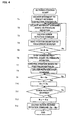
- FIG. 4 is a flowchart showing the metering process the processor 26 of the control apparatus according to the present embodiment executes in accordance with the aforesaid principle of the invention.
- the processor 26 delivers a movement for the retreat of the screw to the preset metering completion position Sb to the screw advancing and retreating servomotor M2 through the servo interface 22 (Step T1). This movement is loaded into an error register that is provided for position loop control in the servo amplifier 24.
- a command for the rotation of the screw at the preset rotating speed is delivered to the servo amplifier 23 through the servo interface 21 (Step T3).
- the servo amplifier 23 On receiving the screw rotation command, moreover, the servo amplifier 23 carries out speed feedback control in accordance with the commanded rotating speed and the speed information fed back from the position/speed detector P1, thereby rotating the screw rotating servomotor M1 at a preset speed.
- the screw retreats as it carries out the pressure control and starts rotation at the preset rotating speed, as shown in FIGS. 3A and 3B, thereby melting and kneading the resin.
- the processor 26 subtracts the position information fed back from the position/speed detector P2, reads a value Sd of an error register that stores a current position deviation (Step T4), and compares it with the position deviation Ss that is set as a rotating speed regulation point and a switching point from the pressure control to the positioning control (Step T5).
- the position deviation Sd is reduced to the preset position deviation Ss or less, the movement command based on the pressure deviation is stopped (or pressure feedback control is stopped). Then, the control mode is switched to the position loop control based on the position deviation (residual movement in the preset metering completion position Sb) stored in the error register, and the positioning control is started (Steps T6 and T7). Further, the rotation stop command (for stopping the speed command) is delivered to the servo amplifier 23 of the screw rotating servomotor M1 (Step T8).
- the preset position deviation Ss is previously obtained and set as a value corresponding to a movement from the start of deceleration to the stop, based on a previously measured screw retreating speed and the acceleration-deceleration time constant of the screw advancing and retreating servomotor M2.
- the actual screw retreating speed may be detected so that a movement required for the deceleration and stopping can be obtained in accordance with the detected retreating speed and the acceleration-deceleration time constant. In this case, this movement is automatically set as the position deviation Ss. In consequence, both the screw retreating speed and the screw rotating speed are reduced, as shown in FIGS. 3A and 3B.
- the screw Since the retreat of the screw is based on a positioning command for the preset metering completion position Sb, the screw is decelerated and located in the preset metering completion position Sb. If it is detected that the preset metering completion position Sb is reached by a current position Sa of the screw 3 (Step T9), therefore, the processor 26 reads a current rotational position Ra, which is obtained in accordance with the position information fed back from the position/speed detector P1, through the servo interface 21, and stores it as a screw rotational amount Rb at the end of the metering operation (Step T10).
- Step T11 If the rotation stop command is inputted so that the drive of the screw rotating servomotor M1 is stopped, as shown in FIG. 3, however, the screw 3 cannot immediately stop, owing to the respective inertias of the motor M1, screw 3, screw drive mechanism, etc., and overruns before it stops. If the processor 26 detects this stopping of the rotation of the screw 3 (Step T11), it detects the current rotational position Ra of the screw 3, and stores it as a screw rotational amount Rs obtained when the rotation of the screw 3 is stopped (Step T12).
- the servo amplifier 23 is supplied with a rotation command for the rotation of the screw 3 for the difference between the screw rotational amount Rs obtained when the rotation of the screw 3 is stopped and the screw rotational amount Rb at the end of the metering operation, in the opposite rotating direction (reverse to the screw rotating direction for the metering process) at the preset rotating speed or the same speed as the rotating speed for metering.
- the screw rotating servomotor M1 is driven (Step T13), and the metering process is terminated.
- the screw 3 is rotated reversely by the amount Ab corresponding to the overrun rotational amount Aa.
- the surplus metered resin quantity that is attributable to the overrun of the screw 3 is corrected, so that the preset metered resin quantity can be obtained.
- the screw rotational amount is detected by means of the position/speed detector that is connected to the servomotor. Alternatively, however, it may be detected by means of a detector that directly detects the rotational amount of the screw.
- the rotational amount for the overrun is obtained from the difference between the screw rotational position Rb obtained in Step T10 at the end of the metering operation and the screw rotational position Rs obtained in Step T12 when the rotation of the screw is stopped.
- a counter for counting pulses may be provided if the position/speed detector P1 outputs the pulses.
- the counter is reset in Step T10, a counter value is read in Step T12, and the rotational amount for the overrun is obtained from the counter value. Further, the time interval from the completion of metering to the subsequent stop of screw rotation may be measured.
- the overrun is calculated on the basis of the measured time and the screw rotating speed, and the calculated value is regarded as a reverse rotational amount.
- a timer is started in Step T10, and the timer is stopped and the time before the deceleration is stopped is measured in Step T12.
- the reverse rotational amount is obtained from the measured time and the preset rotating speed and outputted.
- the overrun rotational amount Aa is previously given repetition stability, it may be preset as the reverse rotational amount Ab so that the screw can be reversely rotated by the preset amount Ab immediately after the screw rotation is decelerated and stopped.
- the processes of Steps T10 and T12 are unnecessary, and the process of Step T13 is a process for reverse rotation by the preset rotational amount Ab.
- a command speed for the reverse rotation may be automatically set according to the rotating speed for metering or may be set by an operator.
- the present invention is applied to an in-line injection molding machine according to the embodiments described above, it may be also applied to a plunger-type injection molding machine.
- the screw advancing and retreating servomotor M2 serves as a plunger advancing and retreating motor, and a plunger advances and retreats by means of the plunger advancing and retreating motor.
- the screw is simply rotated by means of the screw rotating servomotor M1.
- Operation control for the metering process is carried out in like manner provided that the plunger advancing and retreating motor is drivingly controlled in place of the screw advancing and retreating servomotor M2.
- the present invention is applied to a motor-driven injection molding machine according to the foregoing embodiments, it may be also applied to a hydraulic injection molding machine.
- the surplus metered resin quantity that is attributable to overrun such that the screw rotates after the end of the metering operation, owing to the respective inertias of the screw, screw rotation drive mechanism, etc. can be corrected, so that a more accurate preset metered resin quantity can be obtained.
- molded parts can be equalized in weight, and stable molding can be enjoyed.
Landscapes
- Engineering & Computer Science (AREA)
- Manufacturing & Machinery (AREA)
- Mechanical Engineering (AREA)
- Injection Moulding Of Plastics Or The Like (AREA)
Abstract
Description
Claims (8)
- A metering method for an injection molding machine, comprising:obtaining a screw rotational amount after a screw or a plunger retreats up to a preset metering completion position; andreversely rotating the screw by the obtained rotational amount after the rotation of the screw is stopped.
- A metering method for an injection molding machine, comprising:delivering a screw rotation stop command to screw rotation drive means when a screw or a plunger stops after retreating and reaching a preset metering completion position, and measuring the rotational amount of the screw thereafter; andreversely rotating the screw by the measured rotational amount after the stop of the screw rotation.
- A metering method for an injection molding machine, comprising:delivering a screw rotation stop command to screw rotation drive means when a screw or a plunger stops after retreating and reaching a preset metering completion position, and measuring and storing the rotational amount of the screw thereafter; anddelivering the screw rotation stop command to the screw rotation drive means when the screw or the plunger stops after retreating and reaching the preset metering completion position, in a subsequent metering process, and reversely rotating the screw by the stored rotational amount after the rotation of the screw is stopped.
- A control apparatus for an in-line injection molding machine, which comprises a screw advancing and retreating motor for advancing and retreating a screw and a screw rotating motor for rotating the screw, and is designed so that the screw rotating motor is rotated in a given direction during metering operation as the screw advancing and retreating motor is driven to retreat the screw to a preset metering completion position, the apparatus comprising:means for obtaining a rotational amount which represents overrun of the screw during the time from the arrival of the screw at the preset metering completion position to the subsequent deceleration and stop of the screw rotation; andmeans for driving the screw rotating motor to rotate the screw in a direction opposite to the direction for the metering operation in accordance with the obtained rotational amount.
- A control apparatus for an in-line injection molding machine, which comprises a screw advancing and retreating motor for advancing and retreating a screw and a screw rotating motor for rotating the screw, and is designed so that the screw rotating motor is rotated in a given direction during metering operation as the screw advancing and retreating motor is driven to retreat the screw to a preset metering completion position, the apparatus comprising:means for previously setting and storing a rotational amount which represents overrun of the screw during the time from the arrival of the screw at the preset metering completion position to the subsequent deceleration and stop of the screw rotation; andmeans for driving the screw rotating motor to rotate the screw for the stored rotational amount in a direction opposite to the direction for the metering operation after the screw rotation is stopped at the end of the metering operation.
- The control apparatus for an injection molding machine according to claim 4 or 5, wherein said means for rotating the screw in the direction opposite to the direction for the metering operation reversely rotates the screw immediately after the screw rotation is stopped.
- The control apparatus for an injection molding machine according to claim 4 or 5, wherein said means for rotating the screw in the direction opposite to the direction for the metering operation drives the screw rotating motor to rotate the screw at a preset rotating speed in the direction opposite to the direction for the metering operation.
- The control apparatus for an injection molding machine according to claim 4 or 5, wherein said in-line injection molding machine is replaced with a plunger-type injection molding machine, said screw advancing and retreating motor for advancing and retreating the screw is replaced with a plunger advancing and retreating motor for advancing and retreating a plunger, and the plunger is advanced and retreated in place of the screw by means of the plunger advancing and retreating motor.
Applications Claiming Priority (2)
| Application Number | Priority Date | Filing Date | Title |
|---|---|---|---|
| JP2002325435 | 2002-11-08 | ||
| JP2002325435A JP3652681B2 (en) | 2002-11-08 | 2002-11-08 | Metering method and control device in injection molding machine |
Publications (3)
| Publication Number | Publication Date |
|---|---|
| EP1418039A2 true EP1418039A2 (en) | 2004-05-12 |
| EP1418039A3 EP1418039A3 (en) | 2006-05-03 |
| EP1418039B1 EP1418039B1 (en) | 2008-12-31 |
Family
ID=32105502
Family Applications (1)
| Application Number | Title | Priority Date | Filing Date |
|---|---|---|---|
| EP03257052A Expired - Lifetime EP1418039B1 (en) | 2002-11-08 | 2003-11-07 | Metering method and control apparatus for injection molding machine |
Country Status (6)
| Country | Link |
|---|---|
| US (2) | US7235198B2 (en) |
| EP (1) | EP1418039B1 (en) |
| JP (1) | JP3652681B2 (en) |
| CN (2) | CN100431823C (en) |
| DE (1) | DE60325542D1 (en) |
| TW (1) | TWI225003B (en) |
Cited By (1)
| Publication number | Priority date | Publication date | Assignee | Title |
|---|---|---|---|---|
| DE102007020274A1 (en) * | 2007-04-30 | 2008-11-06 | Siemens Ag | Measuring system for detecting a rotary-linear movement and corresponding rotary linear drive |
Families Citing this family (21)
| Publication number | Priority date | Publication date | Assignee | Title |
|---|---|---|---|---|
| JP2005014573A (en) * | 2003-06-30 | 2005-01-20 | Japan Steel Works Ltd:The | Screw pre-plastic injection molding method and apparatus |
| JP4264427B2 (en) * | 2005-05-30 | 2009-05-20 | 日精樹脂工業株式会社 | Injection molding machine weighing method |
| JP4376827B2 (en) * | 2005-06-13 | 2009-12-02 | 日精樹脂工業株式会社 | Measuring method for injection molding machine |
| JP4038226B2 (en) | 2006-02-22 | 2008-01-23 | ファナック株式会社 | Measuring method and control device for injection molding machine |
| JP4231517B2 (en) * | 2006-09-12 | 2009-03-04 | 日精樹脂工業株式会社 | Measuring method for injection molding machine |
| JP4199286B1 (en) * | 2007-06-11 | 2008-12-17 | ファナック株式会社 | Injection molding machine |
| US7713049B2 (en) * | 2007-07-17 | 2010-05-11 | Fanuc Ltd | Injecting molding machine having a torque detecting device |
| JP4410816B2 (en) * | 2007-10-02 | 2010-02-03 | 日精樹脂工業株式会社 | Control device for injection molding machine |
| DE102009012482B4 (en) * | 2009-03-12 | 2013-10-17 | Karl Hehl | Injection molding unit for an injection molding machine for processing plastics |
| CN102275282B (en) * | 2011-08-15 | 2013-06-26 | 富强鑫(宁波)机器制造有限公司 | Plastic control mechanism for multi-component plastic injection molding and control mode of plastic control mechanism |
| JP5507519B2 (en) | 2011-10-14 | 2014-05-28 | ファナック株式会社 | Metering control device for injection molding machine |
| TWI577527B (en) * | 2011-10-28 | 2017-04-11 | 賜福科技股份有限公司 | Shooting mechanism for inject molding |
| JP6177712B2 (en) * | 2014-02-28 | 2017-08-09 | 住友重機械工業株式会社 | Injection molding machine |
| CN107457970A (en) * | 2017-07-25 | 2017-12-12 | 宁波长飞亚塑料机械制造有限公司 | A kind of full motor injection device of motor-direct-drive type of four leading screw four |
| CN110039706A (en) * | 2019-04-18 | 2019-07-23 | 东华机械有限公司 | Full-electric injection molding machine and glue melting control method thereof |
| JP7256718B2 (en) * | 2019-09-06 | 2023-04-12 | ファナック株式会社 | CONTROL DEVICE AND CONTROL METHOD FOR INJECTION MOLDING MACHINE |
| JP7277323B2 (en) * | 2019-09-18 | 2023-05-18 | ファナック株式会社 | CONTROL DEVICE AND CONTROL METHOD FOR INJECTION MOLDING MACHINE |
| JP7420539B2 (en) * | 2019-12-06 | 2024-01-23 | ファナック株式会社 | Injection molding machine control device and control method |
| JP7396884B2 (en) * | 2019-12-11 | 2023-12-12 | ファナック株式会社 | Injection molding machine control device and control method |
| CN111016102B (en) * | 2019-12-17 | 2022-07-01 | 广东伊之密精密注压科技有限公司 | Control method and control device for pressure relief of injection molding machine and injection molding machine |
| JP7520755B2 (en) | 2021-03-16 | 2024-07-23 | 芝浦機械株式会社 | Method for controlling an injection molding machine and injection molding machine |
Family Cites Families (19)
| Publication number | Priority date | Publication date | Assignee | Title |
|---|---|---|---|---|
| US3317962A (en) * | 1965-03-17 | 1967-05-09 | Injection Molders Supply Co In | Injection machine positive stop |
| JPS6110425A (en) | 1984-06-25 | 1986-01-17 | Toshiba Mach Co Ltd | Injection molding machine |
| JPS61230917A (en) * | 1985-04-08 | 1986-10-15 | Fanuc Ltd | Injection pressure control of injection molder |
| JPS62119020A (en) * | 1985-11-20 | 1987-05-30 | Fanuc Ltd | Metering device for injection molding machine |
| EP0228759B1 (en) * | 1985-12-17 | 1990-07-25 | The Japan Steel Works, Ltd. | Injection molding machine and method of control thereof |
| JPS646931A (en) | 1987-06-29 | 1989-01-11 | Sharp Kk | Driving system for liquid crystal display element |
| JPS646931U (en) | 1987-07-02 | 1989-01-17 | ||
| US4879077A (en) * | 1988-02-29 | 1989-11-07 | Nissei Jushi Kogyo Kabushiki Kaisha | Control method of injection molding machine |
| JPH0298421A (en) * | 1988-10-04 | 1990-04-10 | Toyo Mach & Metal Co Ltd | Injection control method for injection molding machine |
| JP2615948B2 (en) | 1988-11-30 | 1997-06-04 | 松下電器産業株式会社 | Injection control method for pre-plastic injection molding machine |
| JP2866019B2 (en) * | 1995-01-27 | 1999-03-08 | 住友重機械工業株式会社 | Injection device of electric injection molding machine |
| JP2814212B2 (en) * | 1995-07-19 | 1998-10-22 | 日精樹脂工業株式会社 | Injection method in injection equipment |
| JP3118188B2 (en) | 1996-07-03 | 2000-12-18 | 住友重機械工業株式会社 | Injection molding method |
| JP3877190B2 (en) | 1997-07-18 | 2007-02-07 | 住友重機械工業株式会社 | Backflow prevention device |
| JPH11240052A (en) | 1998-02-24 | 1999-09-07 | Toyo Mach & Metal Co Ltd | Operation method of injection molding machine |
| JP3250180B2 (en) | 1998-06-17 | 2002-01-28 | 住友重機械工業株式会社 | Depressurization method in plasticization / metering process of electric injection molding machine |
| DE19834086C1 (en) * | 1998-07-29 | 2000-01-05 | Battenfeld Gmbh | Precision method of injection molding using screw piston plasticizer |
| JP3056215B1 (en) | 1999-05-25 | 2000-06-26 | ファナック株式会社 | Injection molding machine metering control device |
| JP3549101B2 (en) * | 2000-06-16 | 2004-08-04 | 日精樹脂工業株式会社 | Injection device with check valve |
-
2002
- 2002-11-08 JP JP2002325435A patent/JP3652681B2/en not_active Expired - Fee Related
-
2003
- 2003-10-27 TW TW092129729A patent/TWI225003B/en not_active IP Right Cessation
- 2003-11-05 CN CNB2006100076222A patent/CN100431823C/en not_active Expired - Fee Related
- 2003-11-05 CN CNB2003101132048A patent/CN1287970C/en not_active Expired - Fee Related
- 2003-11-07 US US10/702,519 patent/US7235198B2/en not_active Expired - Lifetime
- 2003-11-07 EP EP03257052A patent/EP1418039B1/en not_active Expired - Lifetime
- 2003-11-07 DE DE60325542T patent/DE60325542D1/en not_active Expired - Lifetime
-
2006
- 2006-04-28 US US11/412,954 patent/US7435070B2/en not_active Expired - Fee Related
Cited By (3)
| Publication number | Priority date | Publication date | Assignee | Title |
|---|---|---|---|---|
| DE102007020274A1 (en) * | 2007-04-30 | 2008-11-06 | Siemens Ag | Measuring system for detecting a rotary-linear movement and corresponding rotary linear drive |
| DE102007020274B4 (en) * | 2007-04-30 | 2009-04-02 | Siemens Ag | Measuring system for detecting a rotary-linear movement and corresponding rotary linear drive |
| US8035371B2 (en) | 2007-04-30 | 2011-10-11 | Siemens Aktiengesellschaft | Measuring system for detecting a rotary-linear displacement and corresponding rotary-linear drive |
Also Published As
| Publication number | Publication date |
|---|---|
| JP3652681B2 (en) | 2005-05-25 |
| CN1287970C (en) | 2006-12-06 |
| TW200408526A (en) | 2004-06-01 |
| US7435070B2 (en) | 2008-10-14 |
| CN100431823C (en) | 2008-11-12 |
| US7235198B2 (en) | 2007-06-26 |
| CN1827345A (en) | 2006-09-06 |
| EP1418039B1 (en) | 2008-12-31 |
| US20040096534A1 (en) | 2004-05-20 |
| US20060193943A1 (en) | 2006-08-31 |
| CN1498742A (en) | 2004-05-26 |
| JP2004155162A (en) | 2004-06-03 |
| TWI225003B (en) | 2004-12-11 |
| EP1418039A3 (en) | 2006-05-03 |
| DE60325542D1 (en) | 2009-02-12 |
Similar Documents
| Publication | Publication Date | Title |
|---|---|---|
| US7235198B2 (en) | Metering method and control apparatus for injection molding machine | |
| EP1825987B1 (en) | Controller of injection molding machine | |
| US7021917B2 (en) | Injection molding machine metering and control device | |
| US7125232B2 (en) | Controller of injection molding machine | |
| EP0965428B1 (en) | Depressurization method in plasticization and metering process for a motor-driven injection molding machine | |
| EP1708060B1 (en) | Controller for injection molding machine | |
| US7462025B2 (en) | Controller for injection molding machine | |
| EP1136226A1 (en) | Method and apparatus for controlling injection molding machine capable of reducing variations in weight of molded products | |
| US6994537B2 (en) | Electrical injection velocity-pressure switching and pressure holding device | |
| CN100482444C (en) | Controller of injection molding machine | |
| JP2001030317A (en) | Injection apparatus and control method thereof | |
| JP4571163B2 (en) | Suckback amount setting method and injection molding machine | |
| JP2627047B2 (en) | Injection molding machine molding condition setting method | |
| JPH0126857B2 (en) | ||
| JPH11207792A (en) | Control method of in-line screw type injection molding machine | |
| JPH053814B2 (en) | ||
| JP3321437B2 (en) | Injection device and control method thereof | |
| JPH07102593B2 (en) | Injection control method of injection molding machine | |
| JPH06246801A (en) | Injection control method for injection molding machine | |
| JPH0710554B2 (en) | Molding start-up control method and apparatus for injection molding machine | |
| JP2004345282A (en) | Controlling method of injection molding machine |
Legal Events
| Date | Code | Title | Description |
|---|---|---|---|
| PUAI | Public reference made under article 153(3) epc to a published international application that has entered the european phase |
Free format text: ORIGINAL CODE: 0009012 |
|
| AK | Designated contracting states |
Kind code of ref document: A2 Designated state(s): AT BE BG CH CY CZ DE DK EE ES FI FR GB GR HU IE IT LI LU MC NL PT RO SE SI SK TR |
|
| AX | Request for extension of the european patent |
Extension state: AL LT LV MK |
|
| RAP1 | Party data changed (applicant data changed or rights of an application transferred) |
Owner name: FANUC LTD |
|
| PUAL | Search report despatched |
Free format text: ORIGINAL CODE: 0009013 |
|
| AK | Designated contracting states |
Kind code of ref document: A3 Designated state(s): AT BE BG CH CY CZ DE DK EE ES FI FR GB GR HU IE IT LI LU MC NL PT RO SE SI SK TR |
|
| AX | Request for extension of the european patent |
Extension state: AL LT LV MK |
|
| 17P | Request for examination filed |
Effective date: 20061030 |
|
| AKX | Designation fees paid |
Designated state(s): DE |
|
| 17Q | First examination report despatched |
Effective date: 20080102 |
|
| GRAP | Despatch of communication of intention to grant a patent |
Free format text: ORIGINAL CODE: EPIDOSNIGR1 |
|
| GRAS | Grant fee paid |
Free format text: ORIGINAL CODE: EPIDOSNIGR3 |
|
| GRAA | (expected) grant |
Free format text: ORIGINAL CODE: 0009210 |
|
| AK | Designated contracting states |
Kind code of ref document: B1 Designated state(s): DE |
|
| REF | Corresponds to: |
Ref document number: 60325542 Country of ref document: DE Date of ref document: 20090212 Kind code of ref document: P |
|
| PLBE | No opposition filed within time limit |
Free format text: ORIGINAL CODE: 0009261 |
|
| STAA | Information on the status of an ep patent application or granted ep patent |
Free format text: STATUS: NO OPPOSITION FILED WITHIN TIME LIMIT |
|
| 26N | No opposition filed |
Effective date: 20091001 |
|
| PGFP | Annual fee paid to national office [announced via postgrant information from national office to epo] |
Ref country code: DE Payment date: 20091105 Year of fee payment: 7 |
|
| REG | Reference to a national code |
Ref country code: DE Ref legal event code: R119 Ref document number: 60325542 Country of ref document: DE Effective date: 20110601 Ref country code: DE Ref legal event code: R119 Ref document number: 60325542 Country of ref document: DE Effective date: 20110531 |
|
| PG25 | Lapsed in a contracting state [announced via postgrant information from national office to epo] |
Ref country code: DE Free format text: LAPSE BECAUSE OF NON-PAYMENT OF DUE FEES Effective date: 20110531 |