EP1417535B1 - Schaltbare elektrochrome vorrichtungen - Google Patents
Schaltbare elektrochrome vorrichtungen Download PDFInfo
- Publication number
- EP1417535B1 EP1417535B1 EP02744764A EP02744764A EP1417535B1 EP 1417535 B1 EP1417535 B1 EP 1417535B1 EP 02744764 A EP02744764 A EP 02744764A EP 02744764 A EP02744764 A EP 02744764A EP 1417535 B1 EP1417535 B1 EP 1417535B1
- Authority
- EP
- European Patent Office
- Prior art keywords
- window assembly
- conductive coating
- spaced
- electrochromic
- spaced facilities
- Prior art date
- Legal status (The legal status is an assumption and is not a legal conclusion. Google has not performed a legal analysis and makes no representation as to the accuracy of the status listed.)
- Expired - Fee Related
Links
Images

Classifications
-
- B—PERFORMING OPERATIONS; TRANSPORTING
- B64—AIRCRAFT; AVIATION; COSMONAUTICS
- B64C—AEROPLANES; HELICOPTERS
- B64C1/00—Fuselages; Constructional features common to fuselages, wings, stabilising surfaces or the like
- B64C1/14—Windows; Doors; Hatch covers or access panels; Surrounding frame structures; Canopies; Windscreens accessories therefor, e.g. pressure sensors, water deflectors, hinges, seals, handles, latches, windscreen wipers
- B64C1/1476—Canopies; Windscreens or similar transparent elements
- B64C1/1492—Structure and mounting of the transparent elements in the window or windscreen
-
- B—PERFORMING OPERATIONS; TRANSPORTING
- B64—AIRCRAFT; AVIATION; COSMONAUTICS
- B64C—AEROPLANES; HELICOPTERS
- B64C1/00—Fuselages; Constructional features common to fuselages, wings, stabilising surfaces or the like
- B64C1/14—Windows; Doors; Hatch covers or access panels; Surrounding frame structures; Canopies; Windscreens accessories therefor, e.g. pressure sensors, water deflectors, hinges, seals, handles, latches, windscreen wipers
- B64C1/1476—Canopies; Windscreens or similar transparent elements
- B64C1/1484—Windows
-
- G—PHYSICS
- G02—OPTICS
- G02F—OPTICAL DEVICES OR ARRANGEMENTS FOR THE CONTROL OF LIGHT BY MODIFICATION OF THE OPTICAL PROPERTIES OF THE MEDIA OF THE ELEMENTS INVOLVED THEREIN; NON-LINEAR OPTICS; FREQUENCY-CHANGING OF LIGHT; OPTICAL LOGIC ELEMENTS; OPTICAL ANALOGUE/DIGITAL CONVERTERS
- G02F1/00—Devices or arrangements for the control of the intensity, colour, phase, polarisation or direction of light arriving from an independent light source, e.g. switching, gating or modulating; Non-linear optics
- G02F1/01—Devices or arrangements for the control of the intensity, colour, phase, polarisation or direction of light arriving from an independent light source, e.g. switching, gating or modulating; Non-linear optics for the control of the intensity, phase, polarisation or colour
- G02F1/15—Devices or arrangements for the control of the intensity, colour, phase, polarisation or direction of light arriving from an independent light source, e.g. switching, gating or modulating; Non-linear optics for the control of the intensity, phase, polarisation or colour based on an electrochromic effect
- G02F1/153—Constructional details
- G02F1/155—Electrodes
-
- G—PHYSICS
- G02—OPTICS
- G02F—OPTICAL DEVICES OR ARRANGEMENTS FOR THE CONTROL OF LIGHT BY MODIFICATION OF THE OPTICAL PROPERTIES OF THE MEDIA OF THE ELEMENTS INVOLVED THEREIN; NON-LINEAR OPTICS; FREQUENCY-CHANGING OF LIGHT; OPTICAL LOGIC ELEMENTS; OPTICAL ANALOGUE/DIGITAL CONVERTERS
- G02F1/00—Devices or arrangements for the control of the intensity, colour, phase, polarisation or direction of light arriving from an independent light source, e.g. switching, gating or modulating; Non-linear optics
- G02F1/01—Devices or arrangements for the control of the intensity, colour, phase, polarisation or direction of light arriving from an independent light source, e.g. switching, gating or modulating; Non-linear optics for the control of the intensity, phase, polarisation or colour
- G02F1/15—Devices or arrangements for the control of the intensity, colour, phase, polarisation or direction of light arriving from an independent light source, e.g. switching, gating or modulating; Non-linear optics for the control of the intensity, phase, polarisation or colour based on an electrochromic effect
- G02F1/163—Operation of electrochromic cells, e.g. electrodeposition cells; Circuit arrangements therefor
Definitions
- the present invention relates to switchable electrochromic devices that are capable of uniform switching throughout the entire structure and of preferential switching to selected areas. More particularly, the present invention is directed to switchable electrochromic devices, particularly large scale window transparencies and window transparencies of non-uniform shape, which can uniformly switch from an activated to an unactivated state, and which can simultaneously include both an activated area and an unactivated area.
- electrochromic devices are well known in the art for use as mirrors in motor vehicles.
- the patent literature also discusses uses of flat types of electrochromic devices for automotive windows, aircraft window assemblies, sunroofs, skylights, and architectural windows.
- Such electrochromic devices typically include a sealed chamber defined by two pieces of glass that are separated by a gap or space that contains an electrochromic medium.
- the electrochromic medium typically includes anodic compounds and cathodic compounds together in a solution.
- the glass substrates typically include transparent conductive layers coated on facing surfaces of the glass and in contact with the electrochromic medium. The conductive layers on both glass substrates are connected to electronic circuitry.
- an applied potential is introduced into the chamber of the device, which electrically energizes the electrochromic medium and causes the medium to change color.
- the electrochromic medium when it is energized, it can darken and begin to absorb light.
- a photocell can be incorporated into the electrochromic cell to detect a change in light reflected by the mirror and activate the electrical potential to dim the mirror.
- anodic bus bar is typically arranged at the top portion of the mirror assembly, and a cathodic bus bar is typically arranged at the bottom portion of the mirror assembly see e.g. US 6064509.
- the electrochromic medium will typically display non-uniform coloring by initially coloring the perimeter of the cell where the bus bars are located, i.e., closest to the point where the applied potential comes in contact with electrochromic medium, and thereafter coloring toward the center of the cell.
- conductive films having high sheet resistance are used.
- high sheet resistance films require higher voltages and longer time periods to switch.
- the entire assembly is shaded upon application of electrical potential.
- the present invention provides an electrochromic window assembly as recited in claim 1.
- the present invention further provides a method for providing preferential coloring to a portion of an electrochromic window assembly, comprising: providing an electrochromic window assembly comprising first and second spaced apart transparent substrates defining a chamber therebetween, the first transparent substrate having a first conductive coating and the second transparent substrate having a second conductive coating, the chamber containing an electrochromic medium capable of coloring upon application of electrical potential thereto to provide reduced luminous transmittance; electrically connecting a plurality of first spaced facilities to the first conductive coating for providing the electrical potential to the first conductive coating; electrically connecting a plurality of second spaced facilities to the second conductive coating for providing the electrical potential to the second conductive coating; applying an electrical current to selected ones of the plurality of first spaced facilities and to selected ones of the plurality of second spaced facilities to establish the electrical potential through a selected portion of the electrochromic medium such that the selected portion changes color and reduces its luminous transmittance.
- the present invention is directed to single compartment electrochromic window assemblies having uniform switching or coloring, and which are capable of graded shading (i.e. a gradient shading) or preferentially colored areas.
- the electrochromic window assembly includes a first transparent substrate coated with a first electrically conductive coating and a second transparent substrate coated with a second electrically conductive coating.
- the first and second transparent substrates are spaced from each other to define a chamber therebetween, with the first and second conductive coatings facing each other.
- An electrochromic medium which is capable of reduced light transmittance upon application of an electrical potential through the medium, is contained within the chamber.
- a plurality of first spaced facilities is further provided in contact with the first conductive coating, e.g.
- a plurality of second spaced facilities is provided in contact with the second conductive coating, e.g. along opposing ends of the second substrate, for providing electrical current thereto.
- current from a DC power source is applied to the first plurality and second plurality of facilities, an electrical potential is impressed between the coatings and through the electrochromic medium such that the electrochromic medium rapidly and uniformly colors to the desired color, due to the arrangement of the facilities.
- the current can be applied to selected ones of the first and second plurality of facilities and shorted to other selected ones of the first and second plurality of facilities, thereby producing a window assembly including a shaded area in a selected portion of the assembly.
- electrochromic window assembly 10 is depicted. Although not required, in one particular nonlimiting embodiment of the present invention, electrochromic window assembly 10 has a generally symmetrical geometry.
- electrochromic window assembly 10 can be a square or rectangular shaped window assembly. Such symmetrical shaped window assemblies are particularly useful as architectural glazings, such as windows for buildings.
- the size and shape of electrochromic window assembly 10 can be selected according to the particular desired use of the assembly.
- Electrochromic window assembly 10 includes first transparent substrate 20 and second transparent substrate 30.
- substrates can be made of any material known in the art for use in electrochromic devices, such as but not limited to polymeric materials, glass, metal, and the like, and combinations of such materials.
- at least one or both of substrates 20 and 30 are made of glass, for example, float glass.
- first substrate 20 and second substrate 30 are both transparent.
- one or both of substrates 20 and 30 can be colored or tinted.
- each of the transparent substrates and coatings incorporated into the aircraft window assembly 10 has a luminous transmittance of at least 70%.
- luminous transmittance and “light transmittance” mean the measure of the total amount of visible light transmitted through a transparency.
- the luminous transmittance data provided in this specification is measured for CIE standard illuminant A and indicted as LTA.
- First substrate 20 and second substrate 30 are spaced apart and in a substantially parallel facing relationship with respect to each other, defining a chamber 41 therebetween. Such a relationship can be achieved through spacing element 45.
- Spacing element 45 can be positioned in any manner capable of maintaining desired spacing between first substrate 20 and second substrate 30. In one nonlimiting embodiment of the invention, spacing element 45 extends about the perimeter of electrochromic window assembly 10 adjacent the outer edges of first substrate 20 and second substrate 30 in a sealing manner, as is known in the art. Although not required, spacing element 45 can be positioned slightly inward from the outer edges of first substrate 20 and second substrate 30. Such positioning provides a slight overhang of the first and second substrates, which can expose a portion of first and second coatings 29 and 39, discussed below, for improved electrical contact.
- Spacing element 45 can be constructed of any nonelectrically conductive material.
- element 45 is a polymeric material, e.g. curable organic polymeric materials, such as but not limited to a thermoplastic material, thermosetting material, UV curing resin material, and combinations thereof. Epoxy based organic sealing materials are useful as sealing element 45.
- first substrate 20 defines opposing ends 20a and 20c, which are opposite each other, as well as opposing ends 20b and 20d, which are opposite each other.
- second substrate 30 includes opposing ends 30a and 30c, as well as opposing ends 30b and 30d.
- First substrate 20 and second substrate 30 are each provided with a layer of a transparent electrically conductive material in the form of first conductive coating 29 and second conductive coating 39, respectively, on facing major surfaces 21 and 31, respectively, of the substrates.
- First and second conductive coatings 29 and 39 can be any material that is substantially transparent to visible light, bonds well to the substrate surfaces, is resistant to corrosion by any materials within the electrochromic device as well as the atmosphere, and has good electrical conductance.
- coatings 29 and 39 typically include one or more metal or metal oxide coatings such as but not limited to silver, gold, tin oxide, indium tin oxide (ITO), fluorine doped tin oxide (FTO), antimony doped tin oxide, ITO/metal/ITO (IMI), as well as any other materials known in the art.
- Conductive coatings 29 and 39 can be applied by any of several well known methods, including pyrolysis, chemical vapor deposition and magnetron sputtering.
- First and second conductive coatings 29 and 39 can be constructed from the same or different materials.
- coatings useful in the present invention include an electrically conductive fluorine doped tin oxide coated glass available from PPG industries, Inc. of Pittsburgh, Pennsylvania and marketed under the trademark "NESA®", and an electrically conductive indium tin oxide coated glass available from PPG Industries, Inc. and marketed under the trademark "NESATRON®”.
- first and second conductive coatings 29 and 39 have a sheet resistance ranging from 1 to 10 ohms per square, e.g. ranging from 2 to 5 ohms per square.
- the thickness of first and second conductive coatings 29 and 39 can be the same or different relative to each other and the coating thickness can be uniform, i.e. the same general thickness throughout, or nonuniform, i.e. the coating thickness varies.
- the coatings have the same generally uniform thickness, ranging from 5,000 ⁇ to 50,000 ⁇ , e.g. from 13,000 ⁇ to 26,000 ⁇ .
- Electrochromic medium 40 is contained within the chamber 41 formed between first substrate 20 and second substrate 30.
- Electrochromic medium 40 can be any type of material as is known in the art, and can be in any known form, such as but not limited to electrochromic solutions, gels, semi-solid materials, and the like.
- Electrochromic medium 40 includes at least one electrochromic compound or dye that defines a color. Such materials are well known in the art to color to successively darker colors or shades as a larger electrical potential is applied. When the potential is turned off or reversed, the coloring is removed or bleached, allowing full transmittance of light through electrochromic medium 40.
- electrochromic medium 40 is a solution-phase type electrochromic medium, in which a material contained in solution in an ionically conducting electrolyte remains in solution in the electrolyte when electrochemically reduced or oxidized (including a gel).
- electrochromic medium 40 is a surface-confined electrochromic medium, in which a material that is attached directly to an electronically conducting electrode or confined in close proximity thereto remains attached or confined when electrochemically reduced or oxidized.
- electrochromic medium 40 is an electrodeposition-type electrochromic medium, in which a material contained in solution in the ionically conducting electrolyte forms a layer on the electronically conducting electrode when electrochemically reduced or oxidized.
- electrochromic medium 40 includes at least one anodic electrochromic compound and at least one cathodic electrochromic compound, with the anodic compound representing an oxidizable material and the cathodic compound representing a reducible material.
- the anodic electrochromic compound oxidizes and the cathodic electrochromic compound simultaneously reduces.
- Such simultaneous oxidation and reduction results in a change in the absorption coefficient of at least one wavelength in the visible spectrum.
- the combination of such anodic and cathodic electrochromic compounds in electrochromic medium 40 defines the color associated therewith upon application of an electrical potential.
- Such cathodic electrochromic compounds are commonly referred to as viologen dyes, and such anodic electrochromic compounds are commonly referred to as phenazine dyes.
- Electrochromic medium 40 can also include other materials such as solvents, light absorbers, light stabilizers, thermal stabilizers, antioxidants, thickeners, viscosity modifiers and similar materials.
- At least one edge of coating 29 and/or 39 extend at least in close proximity to an edge of the substrate 20 and/or 30, respectively, i.e. to the perimeter edge 11 of assembly 10, e.g. within 2 inches, or 1 inch or 0.5 inches (5.08 cm, or 2.54 cm or 1.27 cm) of the perimeter edge 11.
- the all the edges of coatings 29 and 39 extend at least in close proximity to the perimeter edge 11 of assembly 20, and in one nonlimiting embodiment, all the edges of coating 29 and 39 extend to the edge of their corresponding substrate and thus to the perimeter edge 11 of assembly 10.
- a plurality of first spaced facilities contacts first conductive coating 29, and a plurality of second facilities contact second conductive coating 39.
- the plurality of first spaced comprises a plurality of bus bars 60
- the plurality of second facilities comprise a plurality of bus bars 80.
- bus bars 60 are anodic bus bars while bus bars 80 are cathodic bus bars.
- Such bus bars 60 and 80 provide electrical connection between a DC power source (not shown in Figs. 1-3) and first and second conductive coatings 29 and 39, respectively. Such electrical connection can be established in any known manner.
- each of anodic bus bars 60 can be connected to an anodic conductive wire 65 by solder joint 64, while each of cathodic bus bars 80 can be connected to a cathodic conductive wire 85 by solder joint 84, as shown in Fig. 3.
- a positive current is applied to the anodic bus bars 60 and a negative current is applied to the cathodic bus bars 80, producing an electrical potential therebetween within the electrochromic cell.
- an external cover or insulator (not shown) can be provided about the perimeter edge 11 of electrochromic window assembly 10 to protect spacing assemblies 45, wires 65 and 85 and/or joints 64 and 84.
- the edges of coating 29 extend to the perimeter edge 11 of assembly 10 and anodic bus bars 60, which are in contact with first conductive coating 29, are provided along opposing ends 20a and 20c of first substrate 20. In this manner, electrical current from the power source is provided to the opposing edges of the first conductive coating 29 along opposing ends 20a and 20c of first substrate 20.
- the edges of coating 39 extend to the perimeter edge 11 of assembly 10 and cathodic bus bars 80, which are in contact with second conductive coating 39, are provided along opposing ends 30b and 30d of second substrate 30.
- first and second coatings 29 and 39 to which the electrical current is applied are spaced from each other.
- uniform coloring means that those portions of the electrochromic medium that change color due to the applied electrical potential, all change generally in the same manner, e.g. generally at the same time and/or generally at the same rate.
- bus bars 60 are arranged along opposing edges 20a and 20c as well as along opposing edges 20b and 20d, and bus bars 80 are arranged along opposing edges 30b and 30d as well as along opposing edges 30a and 30c.
- the anodic bus bars 60 are provided about the perimeter of the entire first substrate 20 and the cathodic bus bars 80 are provided about the perimeter of the entire second substrate 30, i.e. bus bars 60 and 80 are positioned about the entire perimeter edge 11 of assembly 10.
- bus bars 60 and bus bars 80 are arranged in alternating fashion, i.e. each bus bar 60 is arranged between each bus bar 80 about the perimeter edge 11 of window assembly 10.
- each anodic bus bar 60 is spaced from each cathodic bus bar 80 along the perimeter edge 11 of the window assembly 10 a distance of at least 0.5 inches (1.27 cm). Such spacing ensures that the current between the bus bars will not short and provides uniform electrical potential through the entire electrochromic device.
- this bus bar configuration provides that even under prolonged application of an electrical potential, dye segregation is minimized. Dye segregation is the tendency of the dyes to migrate toward and concentrate at the portion of the assembly where the electrical power is the greatest, typically along the bus bars.
- Bus bars 60 and 80 can be made of any highly conductive material typically used for bus bars and well known in the art.
- typical bus bar materials include metal foil, e.g. copper foil, metal coating, e.g. gold coatings, and conductive metal containing ceramic paints, e.g. silver ceramic paint.
- bus bars 60 and 80 can be tailored to the particular geometry of the electrochromic window assembly.
- each of bus bars 60 and 80 are at least 0.5 inches (1.27 cm) in length.
- electrochromic medium 40 is capable of changing its color and thus its light transmittance when an electrical potential is applied through the medium.
- Application of the electrical potential can be selective, i.e. the electrochromic window assembly is switchable between one level of transmittance, when no electrical potential is applied, and a second level of transmittance, when electrical potential is applied to change the color of the dyes and reduce the luminous transmittance of the electrochromic medium 40.
- This feature is most easily accomplished by providing a switch for selectively applying electrical current to the window assembly.
- the coloring of the electrochromic medium between the energized and non-energized electrical states is self-erasable, i.e. the coloring of the electrochromic medium when in an electrochemically activated state upon application of an electrical potential, automatically returns or erases to its original state, e.g. colorless state, when the electrical potential is removed.
- the original state can be a colorless state or it can have a color or tint.
- the electrochromic window assembly is switchable and non-self-erasing, i.e. application of the electrical potential causes the electrochromic medium to color, and the electrochromic medium will remain in the colored state until the electrical potential is reversed or shorted.
- the color of the dye can be of a constant darkness or shade upon application of an electrical potential, or it can be of varying degrees of darkness or shading depending upon the magnitude of the electrical potential established through the electrochromic medium.
- specific coloring or shading of the coloring can be varied over a range of voltages and power densities.
- the dye Upon application of a low power density to the electrochromic medium, the dye can begin to color. Increasing the voltage can cause the color of the dye to darken to a deeper shade or intensity.
- the window assembly can include varying degrees of light transmittance upon varying of the electrical potential. The window assembly can, therefore, be adjusted to a desired level of darkness or shading based upon the amount of electrical potential applied thereto.
- the electrochromic window assembly is switchable between a minimum LTA value ranging from 1 to 20 percent and a maximum LTA value ranging from 60 to 80 percent. As such, the electrochromic window assembly can effectively function as an opaque shade for a window when desired.
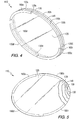
- electrochromic window assembly 110 is in the form of a generally oval shaped window, which can be used, for example, as an aircraft cabin window. Although not required, in this particular embodiment of the invention, the oval shaped window has a symmetrical geometry, as with the embodiment described above.
- electrochromic window assembly 110 includes spaced apart first substrate 120 and second substrate 130, as well as first conductive coating 129, second conductive coating 139 and electrochromic medium 140 therebetween. Coatings 129 and 139 are applied to opposing facing surfaces of substrates 120 and 130, respectively, and electrochromic medium 140 is positioned between the coatings. Substrates 120 and 130 are separated by spacer 145.
- Bus bar 160a is connected to an edge of first conductive coating 129 along first end 120a of first substrate 120, and bus bar 160c is connected to an opposing edge of first conductive coating 129 along opposing second end 120c of first substrate 120.
- bus bar 180b is connected to an edge of second conductive coating 139 along first end 130b of second substrate 130, and bus bar 180d is connected to an opposing edge of second conductive coating 139 along opposing second end 130d of second substrate 130.
- bus bars 160a and 160c are anodic bus bars, while bus bars 180b and 180b are cathodic bus bars.
- bus bars 160 and 180 are longer in length relative to the bus arrangement of Fig. 1.
- each of bus bars 160 and 180 are equal in length, and bus bars 160 and 180 are spaced about the perimeter edge of the assembly 110 at least 0.5 inches (1.27 cm) apart.
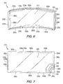
- electrochromic window assembly 210 having a generally symmetrical rectangular geometry. Such an assembly can be useful, for example, as an automobile windshield, rear window or sunroof, or as an architectural glazing.
- electrochromic window assembly 210 includes spaced apart first substrate 220 and second substrate 230, as well as first conductive coating 229, second conductive coating 239 and electrochromic medium 240. Coatings 229 and 239 are applied to opposing facing surfaces of substrates 220 and 230, respectively and electrochromic medium 240 is positioned between the coatings. Substrates 220 and 230 are separated by spacer 245.
- Assembly 210 further includes bus bars 260 and 280.
- bus bars 260 are anodic bus bars and bus bars 280 are cathodic bus bars.
- Anodic bus bars 260a and 260b are connected to a first edge of first conductive coating 229 along first end 220a of first substrate 220, and bus bars 260c and 260d are connected to an opposing edge of first conductive coating 229 along opposing second end 220c of first substrate 220.
- cathodic bus bar 280a is connected to a first edge of second conductive coating 239 along first end 230a of second substrate 230 at a position spaced between anodic bus bars 260a and 260b
- cathodic bus bar 280b is connected to a second opposing edge of second conductive coating 239 along opposing second end 230c of second substrate 230 at a position spaced between anodic bus bars 260c and 260d.
- bus bars 280c and 280d are connected to a third edge of second conductive coating 239 at third end 230b of second substrate 230
- bus bars 280e and 280f are connected to a fourth opposing edge of second conductive coating 239 at opposing fourth end 230d of second substrate 230.
- bus bars 260 and 280 are equal in length, and bus bars 260 and 280 are spaced about the perimeter edge of the assembly 210 at least 0.5 inches (1.27 cm) apart.
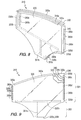
- Electrochromic window assembly 310 includes a non-symmetric geometry. While such a non-symmetrical electrochromic window assembly can be provided for any application, the specific nonlimiting embodiment shown is in the form of an automobile side window, commonly referred to as a sidelite. Electrochromic window assembly 310 includes a first portion 301 and a second portion 302. In use as an automobile sidelite, first portion 301 represents the portion of the window assembly which is above the door panel of an automotive vehicle and visible when the window is closed, while second portion 302 represents the portion of the window assembly that remains below the door panel at all times, including when the window is closed, and is therefore not visible.
- Electrochromic window assembly 310 includes spaced apart first substrate 320 and second substrate 330, as well as first conductive coating 329, second conductive coating 339 and electrochromic medium 340, as with the previously discussed embodiments. Coatings 329 and 339 are applied to opposing facing surfaces of substrates 320 and 330, respectively, and electrochromic medium 340 is positioned between the coatings. Substrates 320 and 330 are separated by spacer 345.
- Electrochromic assembly 310 includes bus bar 360a connected to an edge of first conductive coating 329 along first end 320a of first substrate 320, and bus bar 360b connected to first conductive coating 329 along a lower portion of first substrate 320 near opposing second end 320c.
- bus bar 360b could be positioned along edge 320c of substrate 320, in the particular embodiment of the invention shown in Figs. 8 and 9, bus bar 360b is not positioned along edge 320c, for reasons that will be discussed later in more detail.
- Electrochromic assembly 310 further includes bus bars 380a and 380b connected to a first edge of second conductive coating 339 along first end 330b of second substrate 330, and bus bars 380c, 380d and 380e connected to an opposing second edge of second conductive coating 339 along opposing second end 330d of second substrate 330.
- bus bars 360a and 360b are anodic bus bars
- bus bars 380a, 380b, 380c, 380d and 380e are cathodic bus bars.
- electrochromic window assembly 310 includes a non-symmetrical geometry.
- the side of window assembly 310 formed by first ends 320b and 330b of substrates 320 and 330, respectively, is shorter in length than the opposing side of window assembly 310 formed by second ends 320d and 330d.
- the bus bar arrangement is adjusted to compensate for such non-symmetrical shape.
- two bus bars 380a and 380b are provided in contact with second conductive coating 339 along end 330b, while three bus bars 380c, 380d and 380e are provided in contact with second conductive coating 339 along opposing end 330d.
- bus bars can be adjusted to provide for an appropriate fitting and geometry, as well as appropriate level of current flow. Such an arrangement with differing number and differing lengths of bus bars compensates for the current flow across the electrochemical cell due to the non-symmetrical geometry of the electrochromic window assembly 310.
- the current applied to the bus bars can be adjusted in order to compensate for the non-symmetrical shape.
- resistors (not shown) can be incorporated into the current flow to bus bars 380a and 380b in order to reduce the amount of current flowing to these bus bars. As such, compensation is provided for the applied potential to the non-symmetrical assembly.
- a controller can be used to control the current delivered to each bus bar, as will be discussed later in more detail.
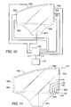
- a single bus bar 360b is provided in electrical contact with first conductive coating 329.
- Such an internal bus bar 360b can be provided, e.g.
- bus bar 360b by adhesively attaching bus bar 360b to first conductive coating 329 with a conductive adhesive along substrate 320.
- a nonelectrically conductive layer (not shown), such as but not limited to adhesive tape, can be placed over bus bar 360b to act as an insulator, preventing bus bar 360b from electrically contacting second conductive coating 339.
- Such adhesive tape can further act as a spacer, maintaining appropriate spacing between first substrate 320 and second substrate 330.
- Internal bus bar 360B can be made of the same materials as discussed earlier for the other bus bars.
- the electrochromic assembly includes at least one bus bar spaced from the edge of the assembly and positioned within the assembly.
- a portion 361 b of internal bus bar 360b extends toward an edge of window 310, for example perpendicularly as shown in Figs. 8 and 9 to edge 320c, to provide external contact with the conductive wire for electrical connection of the bus bar 360b with a power source. Since this internal bus bar arrangement is contained within portion 302 of window assembly 300, none of the components are visible, as portion 302 is maintained within the door panel of the automobile. As an alternative, at least a portion of the bus bar 360b can be positioned within section 301 of assembly 300.
- bus bar contacts can be provided on exterior top and side edges of the window assembly, with separate contact points provided within the frame of the automobile for establishing contact with the power source.
- This arrangement provides an appropriate assembly for automobile windows that are not encased within a door frame, since there is no external cover in such an arrangement to conceal the contacts. Such an arrangement would not be detrimental to the darkening of the window assembly, since closing the window would permit contact with the power source, and since it would not be necessary to shade the window when the window is open.
- the amount of current applied to the electrochromic window assembly can be selected based on the specific assembly and the specific electrochromic medium used. In one nonlimiting embodiment of the invention, the amount of current applied ranges from 0.4 volts to 1.2 volts, e.g. from 0.5 volts to 1.0 volts.
- Electrochromic window assembly provided as described above, is a generally transparent assembly when no electrical potential is applied thereto. As such, electrochromic window assembly 310 is in the lightened state and full light transmittance is possible.
- the electrochromic window assembly is activated, for example by a switch that is activatable by the user. Activation of the switch causes the power source to supply current to bus bars 360 and 380 in any convenient manner, e.g. through the wire leads attached thereto, and to first and second conductive coatings 329 and 339.
- Such current causes an application of electrical potential to the electrochromic medium, which in turn causes the at least one anodic electrochromic compound to oxidize and the at least one cathodic electrochemical compound to reduce.
- This reaction results in a change in color of the electrochromic medium such that the electrochromic medium begins to absorb light and darken. Since the electrical potential between coatings 329 and 339 is applied through the bus bar arrangement as set forth above, the coloring of the electrochromic medium is rapid and uniform throughout the entire electrochromic window assembly, without any iris effect or gradual change in color.
- Deactivation of the assembly 310 causes the supply of power to be interrupted to bus bars 360 and 380. As such, the potential being applied to electrochromic medium 340 is removed. Such deactivation can be affected using the same switch arrangement as discussed above to activate the assembly 310. As discussed earlier, in the case of a self-erasing electrochromic medium, the window assembly 310 will return to its original state. In the case of a non-self-erasing electrochromic medium, the color will remain until the electrical potential through the medium is reversed.
- only a portion of the electrochromic window assembly can be colored to establish a partially shaded window.
- Such partial shading can be achieved by selectively applying current to a selected number of the anodic bus bars and cathodic bus bars, thereby creating the electrical potential through only a portion of the electrochromic window assembly.
- a window assembly 310 is in the form of an automobile sidelite, it can be desirable to create a darkened or shaded top area of the sidelite in order to reduce the level of sunlight transmitted therethrough, while maintaining a lightened state at the middle and bottom areas of the sidelite to maintain a high level of light transmittance therethrough, for example to more easily view the side-view mirrors.
- such preferential area shading can be accomplished, for example, by applying current only to anodic bus bar 360a and cathodic bus bars 380a and 380c, as will be discussed later in more detail.
- Such selective application of current establishes an electrical potential at only a selected portion of electrochromic window assembly 310, and in this particular embodiment, along the top area portion of assembly 310.
- only a portion of the electrochromic medium between these areas of current application will change color, resulting in a partially shaded assembly, i.e.
- the luminous transmittance through the portion of the electrochromic medium between the energized portions of the coatings (due to selective powering of the bus bars) will change as compared to those portions of the electrochromic medium that are not between the energized portions of the coatings.
- the partially shaded window assembly can be achieved by selectively applying current to anodic bus bar 360a and cathodic bus bars 380a and 380c.
- anodic bus bar 360b and cathodic bus bars 380b, 380d and 380e By grounding or shorting the current at the remaining bus bars, namely anodic bus bar 360b and cathodic bus bars 380b, 380d and 380e, no electrical potential is applied to the bottom area of electrochromic window assembly 310.
- the color of electrochromic medium 340 at the bottom portion of assembly 310 is generally maintained in a lightened state, and any bleeding effect of coloring from the top portion which is colored due to application of electrical potential is reduced.
- the electrochromic window assembly can include a gradient shading across the surface thereof, such that electrochromic window assembly gradually changes from a lightened state, through successively darker shaded sections to a darkened state.
- This can be accomplished in a similar manner as described above with respect to the preferentially shaded area, by applying varying voltages to different facilities in order to achieve varying degrees of darkening of the electrochromic medium.
- a voltage of 0.7 volts can be applied to bus bars 360a, 380a and 380c and a decreased voltage of 0.4 volts can be applied to bus bars 380b and 380d.
- electrochromic window assembly 310 can be gradually shaded from a darkened state at the top portion, through a slightly darkened state at the middle portion to a lightened state at the bottom portion.
- electrochromic window assembly 310 it is possible to achieve a gradient shading across the electrochromic window assembly, such that a portion of the electrochromic window assembly is fully colored, while a separate portion of the electrochromic window assembly is only partially colored.
- a voltage of 0.7 volts can be applied to bus bars 360a, 380a and 380c while a voltage of 0.4 volts is applied to bus bars 360b, 380b, 380d and 380e.
- electrochromic window assembly 310 will include a gradient shading from a completely darkened state at the top portion, through a slightly darkened state at the bottom portion.
- the electrochromic window assembly is an automobile windshield, with the portion of the assembly that is selectively colored being the upper edge portion of the windshield, which typically corresponds to the shade band.
- the electrochromic window assembly can be an automobile sunroof, with one side of the assembly being selectively colored.
- this can be accomplished, for example, through application of an electrical current to bus bars 260a, 260c, 280c, and 280d, while shorting bus bars 260b, 260d, 280a, 280b, 280e, and 280f, causing one side portion of electrochromic window assembly 200 to darken and the other side portion to remain in a lightened state.
- this embodiment can also be operated in a manner that darkens one or more selected portions of assembly 10 and/or produces a gradient shading in one or more selected portions of assembly 10.
- a controller can be used to control power distribution to the conductive coatings.
- a controller 390 can be used to control the electrical power supplied to each bus bar in assembly 310 by a DC power source 391. More particularly, controller 390 can control whether a particular bus bar is energized (i.e. current is delivered to the bus bar), not energized or shorted. In addition, controller 390 can control how much current is delivered to the particular bus bar.
- the controller 390 can establish an electrical potential through only a selected portion of the electrochromic medium such that its luminous transmittance through the selected portion is different from its luminous transmittance through its other portions.
- the controller 390 can be used to produce a desired change in the luminous transmittance of the assembly, such as but not limited to, darkening a selected portion of the assembly or providing a gradient shading as discussed earlier.
- the controller 390 can also control the current as required to account for non-symmetrical features of the assembly, e.g. shape, bus bar length, coating thickness, etc.
- An electrochromic window assembly 410 in the form of an automobile side window or sidelite was constructed as follows.
- This first substrate 420 was coated on one surface with a coating 429 of ITO using magnetic sputter vapor deposition (MSVD) techniques which are well known in the art to provide a conductive layer.
- the resistance of the conductive coating 429 was 2 ohms per square and the conductive coating was applied to a thickness of 25,000 ⁇ .
- a second glass substrate 430 similar to that of the first glass substrate 420 was provided with a conductive coating 439 in a similar manner, with the conductive coating 439 being applied to a surface of the second substrate 430 facing the coated surface of the first glass substrate 420.
- Anodic bus bars were provided on opposing edges of the first conductive coating 429. More particularly, a first pair of anodic bus bars 460a and 460b was provided across the top edge of the first substrate 420 using 3 mil thick copper foil strips that were secured to the first conductive coating 429 by a conductive adhesive. A portion of each strip was laminated within assembly 410 and the remainder of each strip was wrapped around the edge of the first substrate 420. Bus bars 460a and 460b were 10.5 inches and 10.25 inches (26.67 cm and 26.04 cm) in length, respectively, and were separated by 0.5 inches (1.27 cm).
- a third anodic bus bar 460c was provided by way of a separate strip of 3 mil thick copper adhesively attached across a lower portion of the first substrate 420 directly on the first conductive coating 429, with a further strip 461 c of copper also adhesively attached directly on the first conductive coating perpendicular to and in contact with bus bar 460c, and extending to the edge of the window assembly 410.
- Adhesive tape was provided as insulation over bus bars 460c and strip 461 c.
- Bus bar 460c was 20.5 inches (52.07 cm) long.
- cathodic bus bars were provided on opposing edges of the second substrate 430 in contact with the second conductive coating 439. More particularly, cathodic bus bars 480a and 480b in the form of two separate copper strips spaced 0.5 inches (1.27 cm) from each other and across one side edge of the second substrate 430 were provided in contact with a first edge of the second conductive coating 439, and cathodic bus bars 480c and 480d in the form of two additional separate copper strips spaced 0.5 inches (1.27 cm) from each other and across the opposite side edge of the second substrate 430 were provided in contact with an opposing edge of the second conductive coating 439. Each of the bus bars were made of 3 mil thick copper foil and secured to the respective conductive coating by a conductive adhesive.
- Bus bars 480a, 480b, 480c and 480d were 4.25 inches, 7.25 inches, 4.25 inches and 11.75 inches (10.80 cm, 18.42 cm, 10.80 cm and 29.85 cm) in length, respectively
- the two glass substrates 420 and 430 were spaced apart approximately 24 mils (0.61 mm), with the conductive coatings 429 and 439 facing each other.
- a polymeric resin was applied between the two substrates around the perimeter of the assembly to act as a spacer.
- An electrochromic medium 440 including a viologen dye and a phenazine dye, capable of coloring upon application of electrical potential thereto was injected between the two substrates.
- the anodic and the cathodic bus bars were connected to a DC power source through wire leads.
- Various levels of current were applied to different sets of bus bars, as set forth below. Because the edge of the assembly 410 along bus bars 480a and 480b is shorter than the opposing edge of the assembly, 0.5 ohm resistors were inserted in line with bus bars 480a and 480b to vary the current and provide a generally uniform power density.
- Example 1 current was applied to all of the anodic and cathodic bus bars at 0.70 volts, and therefore, to the entire electrochromic window assembly 410 with electrical potential evenly distributed throughout the entire assembly. After 5 minutes, the electrochromic window assembly achieved a constant or steady state at 0.092 amps, in which all of the oxidation/reduction reaction had occurred between the anodic and cathodic dye within the electrochromic medium. As can be seen in Table I, the entire electrochromic window assembly achieved an excellent coloring, with the top portion of the window assembly having and LTA of ⁇ 1%, and the bottom portion of the assembly having an LTA of approximately 2%. Thus, the coloring or darkening of the window assembly was achieved quickly and uniformly.
- Example 2 current was applied to only the anodic and cathodic bus bars arranged at the top of the window assembly 410, specifically anodic bus bar 460a and 460b, and cathodic bus bars 480a and 480c, at 0.70 volts.
- the electrochromic window assembly achieved a constant or steady state at 0.065 amps, in which all of the oxidation/reduction reaction had occurred between the anodic and cathodic dye within the electrochromic medium.
- the top portion of the electrochromic window assembly achieved an excellent coloring, having an LTA of ⁇ 1%.
- the bottom portion of the assembly had an LTA of approximately 6-7%.
- the coloring or darkening of the window assembly was non-uniform and had a gradient as viewed from the top to the bottom portion.
- Example 3 current was applied to only the anodic and cathodic bus bars arranged at the top of the window assembly 410, specifically anodic bus bar 460a and 460b and cathodic bus bars 480a and 480c, at 0.70 volts. Further, current to the remaining anodic and cathodic bus bars, namely anodic bus bar 460c and cathodic bus bars 480b and 480d was shorted, i.e. any current reaching these bus bars from the energized bus bars through the conductive coatings was removed.
- the electrochromic window assembly achieved a constant or steady state at 0.154 amps, in which all of the oxidation/reduction reaction had occurred between the anodic and cathodic dye within the electrochromic medium.
- the top portion of the electrochromic window assembly achieved partial coloring, having an LTA of 14%.
- the bottom portion of the assembly had an LTA of approximately 54%, representing no color change and full transmission through the bottom portion of the assembly.
- a partial shade band was achieved across the top of the window assembly, with a small amount of light transmitted through the shade band.
- Example 4 current was applied to only the anodic and cathodic bus bars arranged at the top of the window assembly 410, specifically anodic bus bar 460a and 460b and cathodic bus bars 480a and 480c, as with Example 3, but instead at 0.80 volts. Again, as with Example 3, current to the remaining anodic and cathodic bus bars, namely anodic bus bar 460c and cathodic bus bars 480b and 480d was shorted. After 5 minutes, the electrochromic window assembly achieved a constant or steady state at 0.187 amps, in which all of the oxidation/reduction reaction had occurred between the anodic and cathodic dye within the electrochromic medium.
- the top portion of the electrochromic window assembly achieved excellent coloring, having an LTA of approximately 3%.
- the bottom portion of the assembly had an LTA of approximately 54%, representing no color change and full transmission through the bottom portion of the assembly.
- LTA approximately 54%
Claims (32)
- Elektrochrome Fensteranordnung (10, 110, 210, 310, 410) enthaltend:ein erstes transparentes Substrat (20, 120, 220, 320, 420), enthaltend eine erste leitfähige Beschichtung (29, 129, 229, 329, 429) auf einer Oberfläche (21) von diesem;ein zweites transparentes Substrat (30, 130, 230, 330, 430), enthaltend eine zweite leitfähige Beschichtung (39, 139, 239, 339, 439) auf einer Oberfläche (31) von diesem, wobei das erste transparente Substrat (20, 120, 220, 320, 420) und das zweite transparente Substrat (30, 130, 230, 330, 430) voneinander beabstandet sind, um eine Kammer (41) dazwischen zu bilden;ein in der Kammer (41) enthaltenes elektrochromes Medium (40, 140, 240, 340, 440), wobei das elektrochrome Medium (40, 140, 240, 340, 440) einen Lichtdurchlässigkeitsgrad aufweist, der bei Anlegen einer elektrischen Spannung durch das elektrochrome Medium (40, 140, 240, 340, 440) variiert;eine Vielzahl von ersten beabstandeten Einrichtungen (60, 160, 260, 360, 460), die die erste leitfähige Beschichtung (29, 129, 229, 329, 429) berühren und geeignet sind, elektrischen Strom der ersten leitfähigen Beschichtung (29, 129, 229, 329, 429) zuzuführen;eine Vielzahl von zweiten beabstandeten Einrichtungen (80, 180, 280, 380, 480), die die zweite leitfähige Beschichtung (39, 139, 239, 339, 439) berühren und geeignet sind zum Zuführen von elektrischem Strom zu der zweiten leitfähigen Beschichtung (39, 139, 239, 339, 439), um die elektrische Spannung durch das elektrochrome Medium (40, 140, 240, 340, 440) zu erzeugen; gekennzeichnet durcheine erste Vielzahl von Verbindungsstücken (64), wobei jedes Verbindungsstück der ersten Vielzahl von Verbindungsstücken mit einer entsprechenden der Vielzahl der ersten beabstandeten Einrichtungen (60, 160, 260, 360, 460) verbunden ist, um elektrischen Strom der entsprechenden Einrichtung der Vielzahl von ersten beabstandeten Einrichtungen (60, 160, 260, 360, 460) zuzuführen; undeine zweite Vielzahl von Verbindungsstücken (84), wobei jedes der zweiten Vielzahl von Verbindungsstücken mit einer entsprechenden Einrichtung der Vielzahl von zweiten beabstandeten Einrichtungen (80, 180, 280, 380, 480) verbunden ist, um elektrischen Strom der entsprechenden Einrichtung der Vielzahl von zweiten beabstandeten Einrichtungen (80, 180, 280, 380, 480) zuzuführen.
- Fensteranordnung (10, 110, 210, 310, 410) nach Anspruch 1, bei der die Vielzahl von ersten beabstandeten Einrichtungen (60, 160, 260, 360, 460) und die Vielzahl von zweiten beabstandeten Einrichtungen (80, 180, 280, 380, 480) Stromschienen sind.
- Fensteranordnung (10, 110, 210, 310, 410) nach Anspruch 1, bei der zumindest eine Einrichtung der Vielzahl von ersten beabstandeten Einrichtungen (60, 160, 260, 360, 460) und zumindest eine Einrichtung der Vielzahl von zweiten beabstandeten Einrichtungen (80, 180, 280, 380, 480) um den Umfang (11) der Fensteranordnung (10, 110, 210, 310, 410) herum angeordnet sind, insbesondere die Vielzahl von ersten beabstandeten Einrichtungen (60, 160, 260, 360, 460) und die Vielzahl von zweiten beabstandeten Einrichtungen (80, 180, 280, 380, 480) um den Umfang (11) herum angeordnet sind.
- Fensteranordnung (10, 110, 210, 310, 410) nach Anspruch 3, bei der die Vielzahl von ersten beabstandeten Einrichtungen (60, 160, 260, 360, 460) zwischen der Vielzahl von zweiten beabstandeten Einrichtungen (80, 180, 280, 380, 480) um den Umfang (11) herum angeordnet sind.
- Fensteranordnung (10, 110, 210, 310, 410) nach Anspruch 1, bei der das erste transparente Substrat (20, 120, 220, 320, 420) und das zweite transparente Substrat (30, 130, 230, 330, 430) eine nicht-symmetrische Geometrie aufweisen.
- Fensteranordnung (10, 110, 210, 310, 410) nach Anspruch 1, bei der die Vielzahl von ersten beabstandeten Einrichtungen (60, 160, 260, 360, 460) die erste leitfähige Beschichtung (29, 129, 229, 329, 429) entlang gegenüberliegenden Enden davon (20a, 20c) berührt und die Vielzahl von zweiten beabstandeten Einrichtungen (80, 180, 280, 380, 480) die zweite leitfähige Beschichtung (39, 139, 239, 339, 439) entlang gegenüberliegenden Enden (30b, 30d) davon berührt, wobei die einander gegenüberliegenden Enden (20a, 20c) der ersten leitfähigen Beschichtung (29, 129, 229, 329, 429) und die einander gegenüberliegenden Enden (30b, 30d) der zweiten leitfähigen Beschichtung (39, 139, 239, 339, 439) voneinander beabstandet sind.
- Fensteranordnung (10, 110, 210, 310, 410) nach Anspruch 6, bei der zumindest eines der gegenüberliegenden Enden der ersten leitfähigen Beschichtung (29, 129, 229, 329, 429) zumindest sehr nahe an dem Umfang (11) der Fensteranordnung (10, 110, 210, 310, 410) liegt.
- Fensteranordnung (10, 110, 210, 310, 410) nach Anspruch 7, bei der die einander gegenüberliegenden Enden (20a, 20c) der ersten leitfähigen Beschichtung (29, 129, 229, 329, 429) und die einander gegenüberliegenden Enden (30b, 30d) der zweiten leitfähigen Beschichtung (39, 139, 239, 339, 439) zumindest sehr nahe am Umfang (11) der Fensteranordnung (10, 110, 210, 310, 410) liegen.
- Fensteranordnung (10, 110, 210, 310, 410) nach Anspruch 1, bei der jede der Vielzahl von ersten beabstandeten Einrichtungen (60, 160, 260, 360, 460) von der Größe her gleich ist und jede der Vielzahl von zweiten beabstandeten Einrichtungen (80, 180, 280, 380, 480) von der Größe her gleich ist.
- Fensteranordnung (10, 110, 210, 310, 410) nach Anspruch 1, bei der zumindest eine der Vielzahl der ersten beabstandeten Einrichtungen (60, 160, 260, 360, 460) eine andere Länge als eine andere der Vielzahl von ersten beabstandeten Einrichtungen (60, 160, 260, 360, 460) aufweist.
- Fensteranordnung (10, 110, 210, 310, 410) nach Anspruch 1, bei der jede der Vielzahl von ersten beabstandeten Einrichtungen (60, 160, 260, 360, 460) und der Vielzahl von zweiten beabstandeten Einrichtungen (80, 180, 280, 380, 480) eine Länge von zumindest 0,5 Zoll aufweist.
- Fensteranordnung (10, 110, 210, 310, 410) nach Anspruch 1, bei der die Vielzahl von ersten beabstandeten Einrichtungen (60, 160, 260, 360, 460) mit einem Abstand von zumindest 0,5 Zoll angeordnet ist und die Vielzahl von zweiten beabstandeten Einrichtungen (80, 180, 280, 380, 480) mit einem Abstand von mindestens 0,5 Zoll angeordnet ist.
- Fensteranordnung (10, 110, 210, 310, 410) nach Anspruch 10, bei der jede der Vielzahl von ersten beabstandeten Einrichtungen (60, 160, 260, 360, 460) von jeder der Vielzahl von zweiten beabstandeten Einrichtungen (80, 180, 280, 380, 480) um den Umfang (11) herum mit einem Abstand von zumindest 0,5 Zoll beabstandet ist.
- Fensteranordnung (10, 110, 210, 310, 410) nach Anspruch 1, weiter enthaltend Widerstände, die zum Einstellen des elektrischen Stroms angeordnet sind, der zu zumindest einer der Vielzahl von ersten beabstandeten Einrichtungen (60, 160, 260, 360, 460) geleitet wird.
- Fensteranordnung (10, 110, 210, 310, 410) nach Anspruch 1, weiter enthaltend einen Regler (390), der geeignet ist, die Abgabe des elektrischen Stroms an ausgewählte Einrichtungen der Vielzahl von ersten beabstandeten Einrichtungen (60, 160, 260, 360, 460) und ausgewählte Einrichtungen der Vielzahl von zweiten beabstandeten Einrichtungen (80, 180, 280, 380, 480) so zu steuern oder zu regeln, dass der Lichtdurchlässigkeitsgrad durch einen ersten Abschnitt des elektrochromen Mediums (40, 140, 240, 340, 440) sich von dem Lichtdurchlässigkeitsgrad durch einen zweiten Abschnitt des elektrochromen Mediums (40, 140, 240, 340, 440) unterscheidet.
- Fensteranordnung (10, 110, 210, 310, 410) nach Anspruch 15, bei der der Regler (390) geeignet ist zum Kurzschließen des elektrischen Stroms an anderen ausgewählten Einrichtungen der Vielzahl von ersten beabstandeten Einrichtungen (60, 160, 260, 360, 460) und an anderen ausgewählten Einrichtungen der Vielzahl von zweiten beabstandeten Einrichtungen (80, 180, 280, 380, 480).
- Fensteranordnung (10, 110, 210, 310, 410) nach Anspruch 1, bei der das elektrochrome Medium (40, 140, 240, 340, 440) zumindest eine elektrochrome Anodenverbindung und zumindest eine elektrochrome Kathodenverbindung umfasst, wobei das Anlegen elektrischer Spannung an das elektrochrome Medium (40, 140, 240, 340, 440) gleichzeitige Oxidation der elektrochromen Anodenzusammensetzung und Reduktion der elektrochromen Kathodenzusammensetzung hervorruft, wobei dadurch ein reduzierter Lichtdurchlässigkeitsgrad hervorgerufen wird.
- Fensteranordnung (10, 110, 210, 310, 410) nach Anspruch 1, bei der das elektrochrome Medium (40, 140, 240, 340, 440) selbstlöschend ist.
- Fensteranordnung (10, 110, 210, 310, 410) nach Anspruch 1, bei der die ersten und zweiten transparenten Substrate (20, 120, 220, 320, 420, 30, 130, 230 330, 430) ausgewählt sind aus Glas, Polymermaterialien und Kombinationen von diesen.
- Fensteranordnung (10, 110, 210, 310, 410) nach Anspruch 1, bei der die elektrochrome Fensteranordnung (10, 110, 210, 310, 410) ausgewählt ist aus Fahrzeugwindschutzscheiben, Fahrzeugseitenscheiben, Fahrzeugsonnendächern, Gebäudeverglasungen und Flugzeugfenstern.
- Fensteranordnung (10, 110, 210, 310, 410) nach Anspruch 1, bei der die ersten und zweiten leitfähigen Beschichtungen (29, 129, 229, 329, 429, 39, 139, 239, 339, 439) einen Flächenwiderstand im Bereich von 1 Ohm pro Quadrat bis 10 Ohm pro Quadrat aufweisen.
- Fensteranordnung (10, 110, 210, 310, 410) nach Anspruch 1, bei der die ersten und zweiten leitfähigen Beschichtungen (29, 129, 229, 329, 429, 39, 139, 239, 339, 439) eine Dicke im Bereich von 5.000 Å bis 50.000 Å aufweisen.
- Fensteranordnung (10, 110, 210, 310, 410) nach Anspruch 1, bei der der elektrische Strom auf die ersten und zweiten leitfähigen Beschichtungen (29, 129, 229, 329, 429, 39, 139, 239, 339, 439) im Bereich von 0,5 Volt bis 1,0 Volt angelegt wird.
- Fensteranordnung (10, 110, 210, 310, 410) nach Anspruch 1, bei der der Lichtdurchlässigkeitsgrad zumindest eines Teils der Anordnung zwischen einem minimalen LTA im Bereich von 1 bis 20 % und einem maximalen LTA im Bereich von 60 bis 80 % variiert.
- Verfahren zum Vorsehen einer bevorzugten Färbung eines Abschnitts einer elektrochromen Fensteranordnung (10, 110, 210, 310, 410), enthaltend:das Vorsehen einer elektrochromen Fensteranordnung (10, 110, 210, 310, 410), enthaltend erste und zweite voneinander beabstandete transparente Substrate (20, 120, 220, 320, 420, 30, 130, 230, 330, 430), die eine Kammer (41) zwischen sich bilden, wobei das erste transparente Substrat (20, 120, 220, 320, 420) eine erste leitfähige Beschichtung (29, 129, 229, 329, 429) und das zweite transparente Substrat (30, 130, 230, 330, 430) eine zweite leitfähige Beschichtung (39, 139, 239, 339, 439) aufweist, wobei die Kammer (41) ein elektrochromes Medium (40, 140, 240, 340, 440) enthält, das einfärbbar ist durch Anlegen elektrischer Spannung darauf zum Bereitstellen eines reduzierten Lichtdurchlässigkeitsgrades; das elektrische Verbinden einer Vielzahl von ersten beabstandeten Einrichtungen (60, 160, 260, 360, 460) mit der ersten leitfähigen Beschichtung (29, 129, 229, 329, 429) zum Versorgen der ersten leitfähigen Beschichtung (29, 129, 229, 329, 429) mit der elektrischen Spannung;das elektrische Verbinden einer Vielzahl von zweiten beabstandeten Einrichtungen (80, 180, 280, 380, 480) mit der zweiten leitfähigen Beschichtung (39, 139, 239, 339, 439) zum Versorgen der zweiten leitfähigen Beschichtung (39, 139, 239, 339, 439) mit der elektrischen Spannung;das Aufbringen eines elektrischen Stroms auf ausgewählte Einrichtungen der Vielzahl von ersten beabstandeten Einrichtungen (60, 160, 260, 360, 460) und auf ausgewählte Einrichtungen der Vielzahl von zweiten beabstandeten Einrichtungen (80, 180, 280, 380, 480) zum Einstellen der elektrischen Spannung durch einen ausgewählten Abschnitt des elektrochromen Mediums (40, 140, 240, 340, 440) so, dass der ausgewählte Abschnitt die Farbe ändert und seinen Lichtdurchlässigkeitsgrad vermindert.
- Verfahren nach Anspruch 25, enthaltend das Positionieren einander gegenüberliegender Enden (20a, 20c) der ersten leitfähigen Beschichtung (29, 129, 229, 329, 429) zumindest sehr nahe an einem Umfang (11) der Anordnung (10, 110, 210, 310, 410) und das Anordnen einander gegenüberliegender Enden (30b, 30d) der zweiten leitfähigen Beschichtung (39, 139, 239, 339, 439) zumindest sehr nahe an dem Umfang (11) der Anordnung (10, 110, 210, 310, 410), das elektrische Verbinden der Vielzahl von ersten beabstandeten Einrichtungen (60, 160, 260, 360, 460) mit der ersten leitfähigen Beschichtung (29, 129, 229, 329, 429) entlang den einander gegenüberliegenden Enden (20a. 20c) der ersten leitfähigen Beschichtung (29, 129, 229, 329, 429) und das elektrische Verbinden der Vielzahl von zweiten beabstandeten Einrichtungen (80, 180, 280, 380, 480) mit der zweiten leitfähigen Beschichtung (39, 139, 239, 339, 439) entlang einander gegenüberliegenden Enden (30b, 30d) der zweiten leitfähigen Beschichtung (39, 139, 239, 339, 439).
- Verfahren nach Anspruch 26, enthaltend das Beabstanden der einander gegenüberliegenden Enden (20a, 20c) der ersten leitfähigen Beschichtung (29, 129, 229, 329, 429) von den einander gegenüberliegenden Enden (30b, 30d) der zweiten leitfähigen Beschichtung (39, 139, 239, 339, 439) entlang dem Umfang (11) der Anordnung (10, 110, 210 , 310, 410).
- Verfahren nach Anspruch 25, weiter enthaltend das Kurzschließen des elektrischen Stroms an anderen ausgewählten Einrichtungen der Vielzahl von ersten beabstandeten Einrichtungen (60, 160, 260, 360, 460) und an anderen ausgewählten Einrichtungen der Vielzahl von zweiten beabstandeten Einrichtungen (80, 180, 280, 380, 480).
- Verfahren nach Anspruch 25, weiter enthaltend das Variieren des elektrischen Stroms der, an die ausgewählten Einrichtungen der Vielzahl von ersten beabstandeten Einrichtungen (60, 160, 260, 360, 460) und an die ausgewählten Einrichtungen der Vielzahl von zweiten beabstandeten Einrichtungen (80, 180, 280, 380, 480) angelegt wird, um wechselnde Grade eines verminderten Lichtdurchlässigkeitsgrades an dem ausgewählten Abschnitt des elektrochromen Mediums (40, 140, 240, 340, 440) bereitzustellen.
- Verfahren nach Anspruch 29, bei dem die elektrochrome Fensteranordnung (10, 110, 210, 310, 410) eine Fahrzeugwindschutzscheibe ist und der Abschnitt des elektrochromen Mediums (40, 140, 240, 340, 440) ein Blendenband ist.
- Verfahren nach Anspruch 25, enthaltend das Anordnen der ersten leitfähigen Beschichtung (29, 129, 229, 329, 429) zumindest sehr nahe an einem Umfang (11) der Anordnung (10, 110, 210, 310, 410) und das Anordnen der zweiten leitfähigen Beschichtung (39, 139, 239, 339, 439) zumindest sehr nahe an dem Umfangsrand (11) der Anordnung (10, 110, 210, 310, 410), das elektrische Verbinden der Vielzahl von ersten beabstandeten Einrichtungen (60, 160, 260, 360, 460) mit der ersten leitfähigen Beschichtung (29, 129, 229, 329, 429) um den gesamten Umfang (11) herum, und das elektrische Verbinden der Vielzahl von zweiten beabstandeten Einrichtungen (80, 180, 280, 380, 480) mit der zweiten leitfähigen Beschichtung (39, 139, 239, 339, 439) um den gesamten Umfang (11) herum.
- Verfahren nach Anspruch 31, enthaltend das Beabstanden der Vielzahl von ersten beabstandeten Einrichtungen (60, 160, 260, 360, 460) um den Umfang (11) herum mit einem Abstand von zumindest 0,5 Zoll, das Beabstanden der Vielzahl von zweiten beabstandeten Einrichtungen (80, 180, 280, 380, 480) mit einem Abstand von zumindest 0,5 Zoll um den Umfang (11) herum und das Beabstanden der Vielzahl von ersten beabstandeten Einrichtungen (60, 160, 260, 360, 460) von der Vielzahl von zweiten beabstandeten Einrichtungen (80, 180, 280, 380, 480) um den Umfang (11) herum mit einem Abstand von zumindest 0,5 Zoll.
Applications Claiming Priority (3)
| Application Number | Priority Date | Filing Date | Title |
|---|---|---|---|
| US09/919,151 US6471360B2 (en) | 2000-08-03 | 2001-07-31 | Switchable electrochromic devices with uniform switching and preferential area shading |
| US919151 | 2001-07-31 | ||
| PCT/US2002/020744 WO2003012541A2 (en) | 2001-07-31 | 2002-07-01 | Switchable electrochromic devices |
Publications (2)
| Publication Number | Publication Date |
|---|---|
| EP1417535A2 EP1417535A2 (de) | 2004-05-12 |
| EP1417535B1 true EP1417535B1 (de) | 2005-11-30 |
Family
ID=25441593
Family Applications (1)
| Application Number | Title | Priority Date | Filing Date |
|---|---|---|---|
| EP02744764A Expired - Fee Related EP1417535B1 (de) | 2001-07-31 | 2002-07-01 | Schaltbare elektrochrome vorrichtungen |
Country Status (9)
| Country | Link |
|---|---|
| US (2) | US6471360B2 (de) |
| EP (1) | EP1417535B1 (de) |
| JP (1) | JP3944165B2 (de) |
| CN (1) | CN1308761C (de) |
| AU (1) | AU2002346012A1 (de) |
| BR (1) | BR0211854A (de) |
| DE (1) | DE60207730T2 (de) |
| RU (1) | RU2262729C2 (de) |
| WO (1) | WO2003012541A2 (de) |
Cited By (21)
| Publication number | Priority date | Publication date | Assignee | Title |
|---|---|---|---|---|
| WO2012125332A2 (en) * | 2011-03-16 | 2012-09-20 | Soladigm, Inc. | Multipurpose controller for multistate windows |
| US8705162B2 (en) | 2012-04-17 | 2014-04-22 | View, Inc. | Controlling transitions in optically switchable devices |
| US8864321B2 (en) | 2011-03-16 | 2014-10-21 | View, Inc. | Controlling transitions in optically switchable devices |
| US9030725B2 (en) | 2012-04-17 | 2015-05-12 | View, Inc. | Driving thin film switchable optical devices |
| US9128346B2 (en) | 2009-12-22 | 2015-09-08 | View, Inc. | Onboard controller for multistate windows |
| US9412290B2 (en) | 2013-06-28 | 2016-08-09 | View, Inc. | Controlling transitions in optically switchable devices |
| US9523902B2 (en) | 2011-10-21 | 2016-12-20 | View, Inc. | Mitigating thermal shock in tintable windows |
| US10048561B2 (en) | 2013-02-21 | 2018-08-14 | View, Inc. | Control method for tintable windows |
| US10221612B2 (en) | 2014-02-04 | 2019-03-05 | View, Inc. | Infill electrochromic windows |
| US10303035B2 (en) | 2009-12-22 | 2019-05-28 | View, Inc. | Self-contained EC IGU |
| US11454854B2 (en) | 2017-04-26 | 2022-09-27 | View, Inc. | Displays for tintable windows |
| US11631493B2 (en) | 2020-05-27 | 2023-04-18 | View Operating Corporation | Systems and methods for managing building wellness |
| US11674843B2 (en) | 2015-10-06 | 2023-06-13 | View, Inc. | Infrared cloud detector systems and methods |
| US11687045B2 (en) | 2012-04-13 | 2023-06-27 | View, Inc. | Monitoring sites containing switchable optical devices and controllers |
| US11709409B2 (en) | 2015-10-06 | 2023-07-25 | View, Inc. | Controllers for optically-switchable devices |
| US11733660B2 (en) | 2014-03-05 | 2023-08-22 | View, Inc. | Monitoring sites containing switchable optical devices and controllers |
| US11750594B2 (en) | 2020-03-26 | 2023-09-05 | View, Inc. | Access and messaging in a multi client network |
| US11796886B2 (en) | 2012-04-17 | 2023-10-24 | View, Inc. | Controller for optically-switchable windows |
| US11835834B2 (en) | 2013-06-28 | 2023-12-05 | View, Inc. | Controlling transitions in optically switchable devices |
| US11940705B2 (en) | 2013-02-21 | 2024-03-26 | View, Inc. | Control method for tintable windows |
| US11966142B2 (en) | 2013-02-21 | 2024-04-23 | View, Inc. | Control methods and systems using outside temperature as a driver for changing window tint states |
Families Citing this family (104)
| Publication number | Priority date | Publication date | Assignee | Title |
|---|---|---|---|---|
| JPWO2002039180A1 (ja) * | 2000-11-10 | 2004-03-18 | 株式会社村上開明堂 | 固体型エレクトロクロミック素子及びその素子を用いたミラー装置並びにcrtディスプレイ |
| US6798556B2 (en) * | 2003-01-31 | 2004-09-28 | Rockwell Scientific Licensing, Llc. | Locally-switched reversible electrodeposition optical modulator |
| US7300166B2 (en) * | 2003-03-05 | 2007-11-27 | Electrochromix, Inc. | Electrochromic mirrors and other electrooptic devices |
| US20110209319A1 (en) * | 2003-12-05 | 2011-09-01 | Williams Scott M | Photosensitive cockpit windshield |
| US8064120B2 (en) | 2004-03-12 | 2011-11-22 | The Boeing Company | Aircraft cabin services system including zone controllers for lighting control modules and dimmable windows |
| US8988757B2 (en) * | 2004-03-12 | 2015-03-24 | The Boeing Company | Low vapor pressure solvent for electrochromic devices |
| US7450294B2 (en) * | 2004-03-12 | 2008-11-11 | Boeing Co | Multi-color electrochromic apparatus and methods |
| CA2463461C (en) * | 2004-04-14 | 2012-06-19 | Kenneth R. Fletcher | Method of customizing a vehicle with decals, a vehicle decal assembly and a vehicle customized with decals in accordance with the method |
| US7248392B2 (en) * | 2005-07-01 | 2007-07-24 | Ppg Industries Ohio, Inc. | Vision panel having a multi-layer primer |
| CN100582908C (zh) * | 2005-07-01 | 2010-01-20 | Ppg工业俄亥俄公司 | 具有多个连接器的电致变色显示板 |
| US7173750B2 (en) * | 2005-07-01 | 2007-02-06 | Ppg Industries Ohio, Inc. | Electrochromic vision panel having a plurality of connectors |
| US7586664B2 (en) * | 2005-07-01 | 2009-09-08 | Ppg Industries Ohio, Inc. | Transparent electrode for an electrochromic switchable cell |
| DE102005043898A1 (de) | 2005-09-14 | 2007-03-22 | Airbus Deutschland Gmbh | Fenster-Anordnung zum Einrichten größerer Flugzeugfenster |
| US20080007086A1 (en) * | 2005-12-10 | 2008-01-10 | Ram Pattikonda | Vehicle shading system and method using an electrically controlled transmission control material |
| US7355161B2 (en) | 2005-12-15 | 2008-04-08 | The Boeing Company | Systems and methods for controlling windows with variable light transmission |
| US7990603B2 (en) * | 2006-06-09 | 2011-08-02 | Gentex Corporation | Variable transmission window system |
| US20080005728A1 (en) * | 2006-06-30 | 2008-01-03 | Robert Paul Morris | Methods, systems, and computer program products for enabling cross language access to an addressable entity in an execution environment |
| US7599109B2 (en) * | 2007-01-12 | 2009-10-06 | Hewlett-Packard Development Company, L.P. | Security device |
| US7893890B2 (en) * | 2007-03-05 | 2011-02-22 | The Boeing Company | Electrically dimmable combiner optics for head-up display |
| GB0712826D0 (en) * | 2007-07-03 | 2007-08-08 | Pilkington Group Ltd | RF interference reduction for functional glazings |
| EP2263119B1 (de) * | 2008-04-10 | 2014-09-24 | Sage Electrochromics, Inc. | Steuervorrichtung für mindestens ein elektrochromes fenster, steuersystem für ein oder mehrere elektrochrome fenster, transportmittel mit mindestens einem elektrochromen fenster und mindestens einer steuervorrichtung sowie steuerungsverfahren mindestens eines elektrochromen fensters |
| US8514476B2 (en) | 2008-06-25 | 2013-08-20 | View, Inc. | Multi-pane dynamic window and method for making same |
| US7719751B2 (en) * | 2008-09-17 | 2010-05-18 | Soladigm, Inc. | Electrical contact technique for electrochromic windows |
| US8288678B2 (en) * | 2008-12-18 | 2012-10-16 | Ppg Industries Ohio, Inc. | Device for and method of maintaining a constant distance between a cutting edge and a reference surface |
| FR2942665B1 (fr) * | 2009-03-02 | 2011-11-04 | Saint Gobain | Dispositif electrocommandable a coloration/decoloration homogene sur toute la surface |
| US8889218B2 (en) | 2009-03-12 | 2014-11-18 | Ppg Industries Ohio, Inc. | Foam window mount having an electric conductive layer over a light blocking layer |
| US8105645B2 (en) * | 2009-03-12 | 2012-01-31 | Ppg Industries Ohio, Inc. | Method of applying an electric conductive layer to selected portions of a mounting frame |
| US9664974B2 (en) | 2009-03-31 | 2017-05-30 | View, Inc. | Fabrication of low defectivity electrochromic devices |
| US11314139B2 (en) | 2009-12-22 | 2022-04-26 | View, Inc. | Self-contained EC IGU |
| US10690540B2 (en) | 2015-10-06 | 2020-06-23 | View, Inc. | Multi-sensor having a light diffusing element around a periphery of a ring of photosensors |
| US11592723B2 (en) | 2009-12-22 | 2023-02-28 | View, Inc. | Automated commissioning of controllers in a window network |
| JP5452433B2 (ja) * | 2010-09-17 | 2014-03-26 | アルプス電気株式会社 | 表示装置 |
| US9958750B2 (en) | 2010-11-08 | 2018-05-01 | View, Inc. | Electrochromic window fabrication methods |
| US8711465B2 (en) | 2010-12-08 | 2014-04-29 | View, Inc. | Spacers for insulated glass units |
| US9442339B2 (en) | 2010-12-08 | 2016-09-13 | View, Inc. | Spacers and connectors for insulated glass units |
| US8643933B2 (en) | 2011-12-14 | 2014-02-04 | View, Inc. | Connectors for smart windows |
| WO2012109494A2 (en) | 2011-02-09 | 2012-08-16 | Kinestral Technologies, Inc. | Electrochromic multi-layer devices with spatially coordinated switching |
| US10935865B2 (en) | 2011-03-16 | 2021-03-02 | View, Inc. | Driving thin film switchable optical devices |
| US9778532B2 (en) | 2011-03-16 | 2017-10-03 | View, Inc. | Controlling transitions in optically switchable devices |
| US9645465B2 (en) | 2011-03-16 | 2017-05-09 | View, Inc. | Controlling transitions in optically switchable devices |
| US10429712B2 (en) | 2012-04-20 | 2019-10-01 | View, Inc. | Angled bus bar |
| US11630367B2 (en) | 2011-03-16 | 2023-04-18 | View, Inc. | Driving thin film switchable optical devices |
| KR20130057165A (ko) * | 2011-11-23 | 2013-05-31 | 현대자동차주식회사 | 터치식 디스플레이 미러 |
| US11865632B2 (en) | 2011-12-12 | 2024-01-09 | View, Inc. | Thin-film devices and fabrication |
| US20210394489A1 (en) | 2011-12-12 | 2021-12-23 | View, Inc. | Thin-film devices and fabrication |
| US10802371B2 (en) | 2011-12-12 | 2020-10-13 | View, Inc. | Thin-film devices and fabrication |
| KR102095605B1 (ko) * | 2011-12-12 | 2020-04-16 | 뷰, 인크. | 박막 디바이스 및 제조 |
| US10295880B2 (en) | 2011-12-12 | 2019-05-21 | View, Inc. | Narrow pre-deposition laser deletion |
| US20130222877A1 (en) | 2012-02-28 | 2013-08-29 | Sage Electrochromics, Inc. | Multi-zone electrochromic devices |
| US11950340B2 (en) | 2012-03-13 | 2024-04-02 | View, Inc. | Adjusting interior lighting based on dynamic glass tinting |
| US9341912B2 (en) | 2012-03-13 | 2016-05-17 | View, Inc. | Multi-zone EC windows |
| WO2014078429A1 (en) * | 2012-11-13 | 2014-05-22 | View, Inc. | Multi-zone ec windows |
| US11635666B2 (en) | 2012-03-13 | 2023-04-25 | View, Inc | Methods of controlling multi-zone tintable windows |
| JP6138417B2 (ja) * | 2012-03-14 | 2017-05-31 | スタンレー電気株式会社 | エレクトロクロミック表示素子 |
| US9405165B2 (en) | 2012-03-30 | 2016-08-02 | Gentex Corporation | Controller configured for an electro-optic device and method thereof |
| EP2837205B1 (de) | 2012-04-13 | 2017-02-15 | View, Inc. | Anwendungen zur steuerung optisch schaltbarer vorrichtungen |
| US10964320B2 (en) | 2012-04-13 | 2021-03-30 | View, Inc. | Controlling optically-switchable devices |
| US20230086335A1 (en) * | 2012-04-20 | 2023-03-23 | View, Inc. | Multi-zone ec windows |
| US9080763B2 (en) | 2012-05-17 | 2015-07-14 | GE Lighting Solutions, LLC | Edge lit luminaires for windows |
| WO2014025913A1 (en) | 2012-08-08 | 2014-02-13 | Kinestral Technologies, Inc. | Electrochromic multi-layer devices with composite current modulating structure |
| EP2883108B1 (de) | 2012-08-08 | 2022-06-22 | Kinestral Technologies, Inc. | Mehrschichtige elektrochrome vorrichtungen mit elektrisch leitfähigen schichten |
| US9507233B2 (en) | 2012-08-08 | 2016-11-29 | Kinestral Technologies, Inc. | Electrochromic multi-layer devices with current modulating structure |
| US10288971B2 (en) | 2012-08-23 | 2019-05-14 | View, Inc. | Photonic-powered EC devices |
| US9158172B2 (en) * | 2012-11-14 | 2015-10-13 | Sage Electrochromics, Inc. | Color matched coating for bus bars |
| US9377663B2 (en) | 2013-01-21 | 2016-06-28 | Kinestral Technologies, Inc. | Electrochromic lithium nickel group 4 mixed metal oxides |
| EP2946246B1 (de) | 2013-01-21 | 2019-04-03 | Kinestral Technologies, Inc. | Vielschichtige elektrochrome vorrichtung mit einer auf einem lithium-nickel-oxid basierender anode |
| US9146437B2 (en) | 2013-01-31 | 2015-09-29 | Gentex Corporation | Electro-optic window assembly |
| US11719990B2 (en) | 2013-02-21 | 2023-08-08 | View, Inc. | Control method for tintable windows |
| US11960190B2 (en) | 2013-02-21 | 2024-04-16 | View, Inc. | Control methods and systems using external 3D modeling and schedule-based computing |
| JP6285971B2 (ja) * | 2013-03-08 | 2018-02-28 | セイジ・エレクトロクロミクス,インコーポレイテッド | 複数の独立して制御可能なゾーン及び内部バスバーを有するエレクトロクロミックデバイス |
| US9360729B2 (en) | 2013-03-15 | 2016-06-07 | Kinestral Technologies, Inc. | Electrochromic lithium nickel group 6 mixed metal oxides |
| US8867116B1 (en) | 2013-03-15 | 2014-10-21 | Gentex Corporation | Distate electrochromic device |
| WO2014205014A1 (en) | 2013-06-18 | 2014-12-24 | View, Inc. | Electrochromic devices on non-rectangular shapes |
| US9885935B2 (en) | 2013-06-28 | 2018-02-06 | View, Inc. | Controlling transitions in optically switchable devices |
| US9403590B2 (en) | 2013-07-26 | 2016-08-02 | Gentex Corporation | Electro-optic window assembly EMI shield |
| JP6190216B2 (ja) * | 2013-08-30 | 2017-08-30 | 三菱航空機株式会社 | 航空機の窓、および開口部の閉塞部材 |
| US9365281B2 (en) | 2013-11-19 | 2016-06-14 | Gentex Corporation | Reducing condensation in dimmable window systems |
| US9586669B2 (en) | 2013-11-25 | 2017-03-07 | Gentex Corporation | Aerospace protective dust cover |
| US10884311B2 (en) | 2013-12-24 | 2021-01-05 | View, Inc. | Obscuring bus bars in electrochromic glass structures |
| US11906868B2 (en) | 2013-12-24 | 2024-02-20 | View, Inc. | Obscuring bus bars in electrochromic glass structures |
| EP3087238B1 (de) | 2013-12-24 | 2021-03-17 | View, Inc. | Verbergung von stromschienen in elektrochromen glasstrukturen |
| EP3152111B1 (de) | 2014-06-05 | 2020-07-29 | Gentex Corporation | Staubschutzabdeckungsanordnung mit kantenlicht |
| US10061177B2 (en) | 2014-07-23 | 2018-08-28 | Kinestral Technologies, Inc. | Process for preparing multi-layer electrochromic stacks |
| US10670936B2 (en) | 2014-07-23 | 2020-06-02 | Kinestral Technologies, Inc. | Wet-coating of thin film lithium nickel oxides for electrochromic applications |
| WO2016073848A1 (en) | 2014-11-07 | 2016-05-12 | Gentex Corporation | Full display mirror actuator |
| WO2016201112A1 (en) | 2015-06-09 | 2016-12-15 | Gentex Corporation | Multi-piece bezel for electro-optic window assembly |
| US10589834B2 (en) | 2015-06-09 | 2020-03-17 | Gentex Corporation | Retention of an electro-optic window assembly |
| TWI746446B (zh) | 2015-07-07 | 2021-11-21 | 美商唯景公司 | 用於可著色窗戶之控制方法 |
| US11255722B2 (en) | 2015-10-06 | 2022-02-22 | View, Inc. | Infrared cloud detector systems and methods |
| WO2017075059A1 (en) | 2015-10-29 | 2017-05-04 | View, Inc. | Controllers for optically-switchable devices |
| CN114265251A (zh) * | 2016-04-19 | 2022-04-01 | Sage电致变色显示有限公司 | 包括透明导电氧化物层和汇流条的电致变色装置和其形成方法 |
| JP6229755B2 (ja) * | 2016-04-21 | 2017-11-15 | 大日本印刷株式会社 | 調光フィルム及び調光フィルムの駆動方法 |
| CN109275336A (zh) | 2016-04-29 | 2019-01-25 | 唯景公司 | 光学可切换窗孔中电参数的校准 |
| US11319628B2 (en) | 2016-09-23 | 2022-05-03 | 3M Innovative Properties Company | Articles with resistance gradients for uniform switching |
| US10451949B2 (en) | 2016-10-10 | 2019-10-22 | Gentex Corporation | Polarized window assembly |
| CN110088676A (zh) * | 2016-12-22 | 2019-08-02 | Sage电致变色显示有限公司 | 包括构造为保持连续渐变透射状态的电致变色器件的装置 |
| CN111051978B (zh) | 2017-09-12 | 2023-04-18 | Sage电致变色显示有限公司 | 非发光可变透射设备及其形成方法 |
| JP7083429B2 (ja) | 2018-08-03 | 2022-06-10 | セイジ・エレクトロクロミクス,インコーポレイテッド | 連続的に段階付けされた透過状態を維持するための装置 |
| WO2020084448A1 (en) | 2018-10-21 | 2020-04-30 | Gentex Corporation | Electro-optic window assembly |
| TWI734299B (zh) * | 2018-12-31 | 2021-07-21 | 美商塞奇電致變色公司 | 維持連續分級透射狀態之裝置 |
| EP3908473A4 (de) | 2019-01-07 | 2022-03-02 | Gentex Corporation | Fensteranordnung mit variabler durchlässigkeit |
| CN114041084A (zh) * | 2019-07-25 | 2022-02-11 | 金泰克斯公司 | 分段可变受控电光元件 |
| WO2021056340A1 (zh) * | 2019-09-26 | 2021-04-01 | 京东方科技集团股份有限公司 | 智能玻璃及智能车窗系统 |
| WO2022267975A1 (zh) * | 2021-06-25 | 2022-12-29 | 深圳市光羿科技有限公司 | 电致变色器件及其控制方法和装置 |
Family Cites Families (14)
| Publication number | Priority date | Publication date | Assignee | Title |
|---|---|---|---|---|
| US4233339A (en) * | 1978-10-23 | 1980-11-11 | Timex Corporation | Method for making electrochromic films having improved etch resistance |
| US4416517A (en) * | 1980-12-22 | 1983-11-22 | Corning Glass Works | Electrochromic devices including a mica layer electrolyte |
| US6246507B1 (en) * | 1992-04-02 | 2001-06-12 | Gentex Corporation | Non-planar interior electrochromic rearview mirror for a vehicle |
| JP3194312B2 (ja) * | 1993-03-19 | 2001-07-30 | ソニー株式会社 | 絞り装置 |
| US5668663A (en) * | 1994-05-05 | 1997-09-16 | Donnelly Corporation | Electrochromic mirrors and devices |
| JPH10239716A (ja) * | 1996-12-24 | 1998-09-11 | Nippon Oil Co Ltd | エレクトロクロミック素子用対向電極及び素子 |
| US6064509A (en) * | 1997-08-22 | 2000-05-16 | Gentex Corporation | Clip for use with transparent conductive electrodes in electrochromic devices |
| US6094292A (en) * | 1997-10-15 | 2000-07-25 | Trustees Of Tufts College | Electrochromic window with high reflectivity modulation |
| US6010220A (en) * | 1998-03-23 | 2000-01-04 | Ppg Industries Ohio, Inc. | Tab and bus bar application method |
| US6062920A (en) * | 1998-08-26 | 2000-05-16 | Gentex Corporation | Custom terminal connector for use in electrochromic devices |
| US6239898B1 (en) * | 1998-11-30 | 2001-05-29 | Gentex Corporation | Electrochromic structures |
| US6195192B1 (en) * | 1999-08-02 | 2001-02-27 | Gentex Corporation | Electrochromic materials with enhanced ultraviolet stability |
| US6373618B1 (en) * | 2000-05-04 | 2002-04-16 | Schott-Donnelly, Llc | Chromogenic glazing for automobiles and display filters |
| US6407847B1 (en) * | 2000-07-25 | 2002-06-18 | Gentex Corporation | Electrochromic medium having a color stability |
-
2001
- 2001-07-31 US US09/919,151 patent/US6471360B2/en not_active Expired - Lifetime
-
2002
- 2002-07-01 CN CNB028150562A patent/CN1308761C/zh not_active Expired - Fee Related
- 2002-07-01 WO PCT/US2002/020744 patent/WO2003012541A2/en active IP Right Grant
- 2002-07-01 BR BR0211854-8A patent/BR0211854A/pt not_active IP Right Cessation
- 2002-07-01 EP EP02744764A patent/EP1417535B1/de not_active Expired - Fee Related
- 2002-07-01 DE DE60207730T patent/DE60207730T2/de not_active Expired - Fee Related
- 2002-07-01 AU AU2002346012A patent/AU2002346012A1/en not_active Abandoned
- 2002-07-01 RU RU2004105943/28A patent/RU2262729C2/ru not_active IP Right Cessation
- 2002-07-01 JP JP2003517667A patent/JP3944165B2/ja not_active Expired - Fee Related
- 2002-10-08 US US10/266,396 patent/US7130101B2/en not_active Expired - Lifetime
Cited By (42)
| Publication number | Priority date | Publication date | Assignee | Title |
|---|---|---|---|---|
| US10001691B2 (en) | 2009-12-22 | 2018-06-19 | View, Inc. | Onboard controller for multistate windows |
| US9128346B2 (en) | 2009-12-22 | 2015-09-08 | View, Inc. | Onboard controller for multistate windows |
| US10303035B2 (en) | 2009-12-22 | 2019-05-28 | View, Inc. | Self-contained EC IGU |
| US9442341B2 (en) | 2009-12-22 | 2016-09-13 | View, Inc. | Onboard controller for multistate windows |
| US10268098B2 (en) | 2009-12-22 | 2019-04-23 | View, Inc. | Onboard controller for multistate windows |
| US9436055B2 (en) | 2009-12-22 | 2016-09-06 | View, Inc. | Onboard controller for multistate windows |
| WO2012125332A3 (en) * | 2011-03-16 | 2012-11-22 | Soladigm, Inc. | Multipurpose controller for multistate windows |
| US9482922B2 (en) | 2011-03-16 | 2016-11-01 | View, Inc. | Multipurpose controller for multistate windows |
| WO2012125332A2 (en) * | 2011-03-16 | 2012-09-20 | Soladigm, Inc. | Multipurpose controller for multistate windows |
| US8864321B2 (en) | 2011-03-16 | 2014-10-21 | View, Inc. | Controlling transitions in optically switchable devices |
| US9454055B2 (en) | 2011-03-16 | 2016-09-27 | View, Inc. | Multipurpose controller for multistate windows |
| US10254618B2 (en) | 2011-10-21 | 2019-04-09 | View, Inc. | Mitigating thermal shock in tintable windows |
| US9523902B2 (en) | 2011-10-21 | 2016-12-20 | View, Inc. | Mitigating thermal shock in tintable windows |
| US11687045B2 (en) | 2012-04-13 | 2023-06-27 | View, Inc. | Monitoring sites containing switchable optical devices and controllers |
| US9348192B2 (en) | 2012-04-17 | 2016-05-24 | View, Inc. | Controlling transitions in optically switchable devices |
| US11927867B2 (en) | 2012-04-17 | 2024-03-12 | View, Inc. | Driving thin film switchable optical devices |
| US9454056B2 (en) | 2012-04-17 | 2016-09-27 | View, Inc. | Driving thin film switchable optical devices |
| US9423664B2 (en) | 2012-04-17 | 2016-08-23 | View, Inc. | Controlling transitions in optically switchable devices |
| US9477131B2 (en) | 2012-04-17 | 2016-10-25 | View, Inc. | Driving thin film switchable optical devices |
| US11796886B2 (en) | 2012-04-17 | 2023-10-24 | View, Inc. | Controller for optically-switchable windows |
| US11592724B2 (en) | 2012-04-17 | 2023-02-28 | View, Inc. | Driving thin film switchable optical devices |
| US9081247B1 (en) | 2012-04-17 | 2015-07-14 | View, Inc. | Driving thin film switchable optical devices |
| US9030725B2 (en) | 2012-04-17 | 2015-05-12 | View, Inc. | Driving thin film switchable optical devices |
| US8705162B2 (en) | 2012-04-17 | 2014-04-22 | View, Inc. | Controlling transitions in optically switchable devices |
| US10048561B2 (en) | 2013-02-21 | 2018-08-14 | View, Inc. | Control method for tintable windows |
| US11940705B2 (en) | 2013-02-21 | 2024-03-26 | View, Inc. | Control method for tintable windows |
| US11966142B2 (en) | 2013-02-21 | 2024-04-23 | View, Inc. | Control methods and systems using outside temperature as a driver for changing window tint states |
| US11835834B2 (en) | 2013-06-28 | 2023-12-05 | View, Inc. | Controlling transitions in optically switchable devices |
| US9412290B2 (en) | 2013-06-28 | 2016-08-09 | View, Inc. | Controlling transitions in optically switchable devices |
| US10120258B2 (en) | 2013-06-28 | 2018-11-06 | View, Inc. | Controlling transitions in optically switchable devices |
| US10221612B2 (en) | 2014-02-04 | 2019-03-05 | View, Inc. | Infill electrochromic windows |
| US11733660B2 (en) | 2014-03-05 | 2023-08-22 | View, Inc. | Monitoring sites containing switchable optical devices and controllers |
| US11674843B2 (en) | 2015-10-06 | 2023-06-13 | View, Inc. | Infrared cloud detector systems and methods |
| US11709409B2 (en) | 2015-10-06 | 2023-07-25 | View, Inc. | Controllers for optically-switchable devices |
| US11740529B2 (en) | 2015-10-06 | 2023-08-29 | View, Inc. | Controllers for optically-switchable devices |
| US11513412B2 (en) | 2017-04-26 | 2022-11-29 | View, Inc. | Displays for tintable windows |
| US11493819B2 (en) | 2017-04-26 | 2022-11-08 | View, Inc. | Displays for tintable windows |
| US11467464B2 (en) | 2017-04-26 | 2022-10-11 | View, Inc. | Displays for tintable windows |
| US11454854B2 (en) | 2017-04-26 | 2022-09-27 | View, Inc. | Displays for tintable windows |
| US11750594B2 (en) | 2020-03-26 | 2023-09-05 | View, Inc. | Access and messaging in a multi client network |
| US11882111B2 (en) | 2020-03-26 | 2024-01-23 | View, Inc. | Access and messaging in a multi client network |
| US11631493B2 (en) | 2020-05-27 | 2023-04-18 | View Operating Corporation | Systems and methods for managing building wellness |
Also Published As
| Publication number | Publication date |
|---|---|
| BR0211854A (pt) | 2004-09-08 |
| RU2004105943A (ru) | 2005-04-10 |
| US20030047457A1 (en) | 2003-03-13 |
| JP3944165B2 (ja) | 2007-07-11 |
| US6471360B2 (en) | 2002-10-29 |
| CN1537257A (zh) | 2004-10-13 |
| US20020135881A1 (en) | 2002-09-26 |
| WO2003012541A2 (en) | 2003-02-13 |
| AU2002346012A1 (en) | 2003-02-17 |
| DE60207730D1 (de) | 2006-01-05 |
| CN1308761C (zh) | 2007-04-04 |
| JP2004537755A (ja) | 2004-12-16 |
| RU2262729C2 (ru) | 2005-10-20 |
| EP1417535A2 (de) | 2004-05-12 |
| US7130101B2 (en) | 2006-10-31 |
| DE60207730T2 (de) | 2006-07-20 |
| WO2003012541A3 (en) | 2003-07-03 |
Similar Documents
| Publication | Publication Date | Title |
|---|---|---|
| EP1417535B1 (de) | Schaltbare elektrochrome vorrichtungen | |
| EP1913439B1 (de) | Vision-schirm mit mehrschicht-grundbeschichtung | |
| CA2611551C (en) | An electrochromic vision panel having a plurality of connectors | |
| JP2004537755A5 (de) | ||
| CN100582908C (zh) | 具有多个连接器的电致变色显示板 | |
| US6783099B2 (en) | Switchable electrochromic devices for use in aircraft transparency windows | |
| US20020118437A1 (en) | Colored electrochromic transparent window assemblies | |
| US20200393731A1 (en) | Electrochromic device with separately controllable zones |
Legal Events
| Date | Code | Title | Description |
|---|---|---|---|
| PUAI | Public reference made under article 153(3) epc to a published international application that has entered the european phase |
Free format text: ORIGINAL CODE: 0009012 |
|
| 17P | Request for examination filed |
Effective date: 20040227 |
|
| AK | Designated contracting states |
Kind code of ref document: A2 Designated state(s): AT BE CH CY DE DK ES FI FR GB GR IE IT LI LU MC NL PT SE TR |
|
| AX | Request for extension of the european patent |
Extension state: AL LT LV MK RO SI |
|
| GRAP | Despatch of communication of intention to grant a patent |
Free format text: ORIGINAL CODE: EPIDOSNIGR1 |
|
| RBV | Designated contracting states (corrected) |
Designated state(s): DE FR GB IT |
|
| GRAS | Grant fee paid |
Free format text: ORIGINAL CODE: EPIDOSNIGR3 |
|
| GRAA | (expected) grant |
Free format text: ORIGINAL CODE: 0009210 |
|
| AK | Designated contracting states |
Kind code of ref document: B1 Designated state(s): DE FR GB IT |
|
| REG | Reference to a national code |
Ref country code: GB Ref legal event code: FG4D |
|
| REF | Corresponds to: |
Ref document number: 60207730 Country of ref document: DE Date of ref document: 20060105 Kind code of ref document: P |
|
| ET | Fr: translation filed | ||
| PLBE | No opposition filed within time limit |
Free format text: ORIGINAL CODE: 0009261 |
|
| STAA | Information on the status of an ep patent application or granted ep patent |
Free format text: STATUS: NO OPPOSITION FILED WITHIN TIME LIMIT |
|
| 26N | No opposition filed |
Effective date: 20060831 |
|
| PGFP | Annual fee paid to national office [announced via postgrant information from national office to epo] |
Ref country code: DE Payment date: 20090729 Year of fee payment: 8 |
|
| PGFP | Annual fee paid to national office [announced via postgrant information from national office to epo] |
Ref country code: IT Payment date: 20090727 Year of fee payment: 8 |
|
| PG25 | Lapsed in a contracting state [announced via postgrant information from national office to epo] |
Ref country code: DE Free format text: LAPSE BECAUSE OF NON-PAYMENT OF DUE FEES Effective date: 20110201 |
|
| REG | Reference to a national code |
Ref country code: DE Ref legal event code: R119 Ref document number: 60207730 Country of ref document: DE Effective date: 20110201 |
|
| PG25 | Lapsed in a contracting state [announced via postgrant information from national office to epo] |
Ref country code: IT Free format text: LAPSE BECAUSE OF NON-PAYMENT OF DUE FEES Effective date: 20100701 |
|
| PGFP | Annual fee paid to national office [announced via postgrant information from national office to epo] |
Ref country code: GB Payment date: 20120725 Year of fee payment: 11 |
|
| PGFP | Annual fee paid to national office [announced via postgrant information from national office to epo] |
Ref country code: FR Payment date: 20130717 Year of fee payment: 12 |
|
| GBPC | Gb: european patent ceased through non-payment of renewal fee |
Effective date: 20130701 |
|
| PG25 | Lapsed in a contracting state [announced via postgrant information from national office to epo] |
Ref country code: GB Free format text: LAPSE BECAUSE OF NON-PAYMENT OF DUE FEES Effective date: 20130701 |
|
| REG | Reference to a national code |
Ref country code: FR Ref legal event code: ST Effective date: 20150331 |
|
| PG25 | Lapsed in a contracting state [announced via postgrant information from national office to epo] |
Ref country code: FR Free format text: LAPSE BECAUSE OF NON-PAYMENT OF DUE FEES Effective date: 20140731 |