EP1417081B1 - Apparatus and method for mixing and dispensing an additive-enhanced slurry - Google Patents
Apparatus and method for mixing and dispensing an additive-enhanced slurry Download PDFInfo
- Publication number
- EP1417081B1 EP1417081B1 EP02744828A EP02744828A EP1417081B1 EP 1417081 B1 EP1417081 B1 EP 1417081B1 EP 02744828 A EP02744828 A EP 02744828A EP 02744828 A EP02744828 A EP 02744828A EP 1417081 B1 EP1417081 B1 EP 1417081B1
- Authority
- EP
- European Patent Office
- Prior art keywords
- slurry
- conduit
- spout
- pressure
- mixer
- Prior art date
- Legal status (The legal status is an assumption and is not a legal conclusion. Google has not performed a legal analysis and makes no representation as to the accuracy of the status listed.)
- Expired - Lifetime
Links
- 239000002002 slurry Substances 0.000 title claims abstract description 136
- 239000000654 additive Substances 0.000 title claims abstract description 33
- 230000000996 additive effect Effects 0.000 title claims abstract description 27
- 238000000034 method Methods 0.000 title claims abstract description 17
- 229910052602 gypsum Inorganic materials 0.000 claims abstract description 58
- 239000010440 gypsum Substances 0.000 claims abstract description 58
- 239000003638 chemical reducing agent Substances 0.000 claims abstract description 20
- 238000004891 communication Methods 0.000 claims abstract description 6
- 238000007599 discharging Methods 0.000 claims abstract description 4
- 238000004519 manufacturing process Methods 0.000 claims description 20
- 239000000203 mixture Substances 0.000 claims description 20
- XLYOFNOQVPJJNP-UHFFFAOYSA-N water Substances O XLYOFNOQVPJJNP-UHFFFAOYSA-N 0.000 claims description 13
- 230000008859 change Effects 0.000 claims description 5
- 239000006185 dispersion Substances 0.000 claims description 3
- 239000012530 fluid Substances 0.000 claims description 3
- 210000003205 muscle Anatomy 0.000 claims description 2
- 239000006260 foam Substances 0.000 description 35
- 239000000463 material Substances 0.000 description 10
- 230000002028 premature Effects 0.000 description 9
- 239000000047 product Substances 0.000 description 9
- OSGAYBCDTDRGGQ-UHFFFAOYSA-L calcium sulfate Chemical compound [Ca+2].[O-]S([O-])(=O)=O OSGAYBCDTDRGGQ-UHFFFAOYSA-L 0.000 description 6
- 230000007704 transition Effects 0.000 description 6
- 239000006265 aqueous foam Substances 0.000 description 5
- 230000001276 controlling effect Effects 0.000 description 5
- 210000002445 nipple Anatomy 0.000 description 4
- 238000005516 engineering process Methods 0.000 description 3
- 238000002347 injection Methods 0.000 description 3
- 239000007924 injection Substances 0.000 description 3
- 230000009467 reduction Effects 0.000 description 3
- 229920002472 Starch Polymers 0.000 description 2
- 239000000853 adhesive Substances 0.000 description 2
- 230000001070 adhesive effect Effects 0.000 description 2
- 229910052925 anhydrite Inorganic materials 0.000 description 2
- 230000008901 benefit Effects 0.000 description 2
- 239000011230 binding agent Substances 0.000 description 2
- 230000015572 biosynthetic process Effects 0.000 description 2
- 238000006243 chemical reaction Methods 0.000 description 2
- 239000002270 dispersing agent Substances 0.000 description 2
- 238000009826 distribution Methods 0.000 description 2
- 235000012489 doughnuts Nutrition 0.000 description 2
- 238000009472 formulation Methods 0.000 description 2
- 238000012423 maintenance Methods 0.000 description 2
- 239000011268 mixed slurry Substances 0.000 description 2
- 230000002093 peripheral effect Effects 0.000 description 2
- 230000001105 regulatory effect Effects 0.000 description 2
- 239000008107 starch Substances 0.000 description 2
- 235000019698 starch Nutrition 0.000 description 2
- 238000003466 welding Methods 0.000 description 2
- 239000004593 Epoxy Substances 0.000 description 1
- 230000009471 action Effects 0.000 description 1
- 238000013019 agitation Methods 0.000 description 1
- WYTGDNHDOZPMIW-RCBQFDQVSA-N alstonine Natural products C1=CC2=C3C=CC=CC3=NC2=C2N1C[C@H]1[C@H](C)OC=C(C(=O)OC)[C@H]1C2 WYTGDNHDOZPMIW-RCBQFDQVSA-N 0.000 description 1
- ZOMBKNNSYQHRCA-UHFFFAOYSA-J calcium sulfate hemihydrate Chemical compound O.[Ca+2].[Ca+2].[O-]S([O-])(=O)=O.[O-]S([O-])(=O)=O ZOMBKNNSYQHRCA-UHFFFAOYSA-J 0.000 description 1
- 238000005266 casting Methods 0.000 description 1
- 239000000470 constituent Substances 0.000 description 1
- 238000010276 construction Methods 0.000 description 1
- 238000006073 displacement reaction Methods 0.000 description 1
- 230000008030 elimination Effects 0.000 description 1
- 238000003379 elimination reaction Methods 0.000 description 1
- 239000000945 filler Substances 0.000 description 1
- 239000012467 final product Substances 0.000 description 1
- 239000003365 glass fiber Substances 0.000 description 1
- 230000005484 gravity Effects 0.000 description 1
- 230000007246 mechanism Effects 0.000 description 1
- 238000012986 modification Methods 0.000 description 1
- 230000004048 modification Effects 0.000 description 1
- 239000001205 polyphosphate Substances 0.000 description 1
- 235000011176 polyphosphates Nutrition 0.000 description 1
- 230000008569 process Effects 0.000 description 1
- 230000008439 repair process Effects 0.000 description 1
- -1 retarders Substances 0.000 description 1
- 238000000926 separation method Methods 0.000 description 1
- UGTZMIPZNRIWHX-UHFFFAOYSA-K sodium trimetaphosphate Chemical compound [Na+].[Na+].[Na+].[O-]P1(=O)OP([O-])(=O)OP([O-])(=O)O1 UGTZMIPZNRIWHX-UHFFFAOYSA-K 0.000 description 1
- 239000007858 starting material Substances 0.000 description 1
- 239000000126 substance Substances 0.000 description 1
- 239000000758 substrate Substances 0.000 description 1
- 238000009827 uniform distribution Methods 0.000 description 1
Images

Classifications
-
- B—PERFORMING OPERATIONS; TRANSPORTING
- B28—WORKING CEMENT, CLAY, OR STONE
- B28B—SHAPING CLAY OR OTHER CERAMIC COMPOSITIONS; SHAPING SLAG; SHAPING MIXTURES CONTAINING CEMENTITIOUS MATERIAL, e.g. PLASTER
- B28B19/00—Machines or methods for applying the material to surfaces to form a permanent layer thereon
- B28B19/0092—Machines or methods for applying the material to surfaces to form a permanent layer thereon to webs, sheets or the like, e.g. of paper, cardboard
-
- B—PERFORMING OPERATIONS; TRANSPORTING
- B01—PHYSICAL OR CHEMICAL PROCESSES OR APPARATUS IN GENERAL
- B01F—MIXING, e.g. DISSOLVING, EMULSIFYING OR DISPERSING
- B01F35/00—Accessories for mixers; Auxiliary operations or auxiliary devices; Parts or details of general application
- B01F35/75—Discharge mechanisms
-
- B—PERFORMING OPERATIONS; TRANSPORTING
- B01—PHYSICAL OR CHEMICAL PROCESSES OR APPARATUS IN GENERAL
- B01F—MIXING, e.g. DISSOLVING, EMULSIFYING OR DISPERSING
- B01F23/00—Mixing according to the phases to be mixed, e.g. dispersing or emulsifying
- B01F23/50—Mixing liquids with solids
- B01F23/53—Mixing liquids with solids using driven stirrers
-
- B—PERFORMING OPERATIONS; TRANSPORTING
- B01—PHYSICAL OR CHEMICAL PROCESSES OR APPARATUS IN GENERAL
- B01F—MIXING, e.g. DISSOLVING, EMULSIFYING OR DISPERSING
- B01F27/00—Mixers with rotary stirring devices in fixed receptacles; Kneaders
- B01F27/80—Mixers with rotary stirring devices in fixed receptacles; Kneaders with stirrers rotating about a substantially vertical axis
- B01F27/81—Mixers with rotary stirring devices in fixed receptacles; Kneaders with stirrers rotating about a substantially vertical axis the stirrers having central axial inflow and substantially radial outflow
- B01F27/811—Mixers with rotary stirring devices in fixed receptacles; Kneaders with stirrers rotating about a substantially vertical axis the stirrers having central axial inflow and substantially radial outflow with the inflow from one side only, e.g. stirrers placed on the bottom of the receptacle, or used as a bottom discharge pump
-
- B—PERFORMING OPERATIONS; TRANSPORTING
- B28—WORKING CEMENT, CLAY, OR STONE
- B28C—PREPARING CLAY; PRODUCING MIXTURES CONTAINING CLAY OR CEMENTITIOUS MATERIAL, e.g. PLASTER
- B28C5/00—Apparatus or methods for producing mixtures of cement with other substances, e.g. slurries, mortars, porous or fibrous compositions
- B28C5/02—Apparatus or methods for producing mixtures of cement with other substances, e.g. slurries, mortars, porous or fibrous compositions without using driven mechanical means effecting the mixing
- B28C5/06—Apparatus or methods for producing mixtures of cement with other substances, e.g. slurries, mortars, porous or fibrous compositions without using driven mechanical means effecting the mixing the mixing being effected by the action of a fluid
-
- B—PERFORMING OPERATIONS; TRANSPORTING
- B28—WORKING CEMENT, CLAY, OR STONE
- B28C—PREPARING CLAY; PRODUCING MIXTURES CONTAINING CLAY OR CEMENTITIOUS MATERIAL, e.g. PLASTER
- B28C5/00—Apparatus or methods for producing mixtures of cement with other substances, e.g. slurries, mortars, porous or fibrous compositions
- B28C5/08—Apparatus or methods for producing mixtures of cement with other substances, e.g. slurries, mortars, porous or fibrous compositions using driven mechanical means affecting the mixing
- B28C5/10—Mixing in containers not actuated to effect the mixing
- B28C5/12—Mixing in containers not actuated to effect the mixing with stirrers sweeping through the materials, e.g. with incorporated feeding or discharging means or with oscillating stirrers
- B28C5/16—Mixing in containers not actuated to effect the mixing with stirrers sweeping through the materials, e.g. with incorporated feeding or discharging means or with oscillating stirrers the stirrers having motion about a vertical or steeply inclined axis
-
- B—PERFORMING OPERATIONS; TRANSPORTING
- B28—WORKING CEMENT, CLAY, OR STONE
- B28C—PREPARING CLAY; PRODUCING MIXTURES CONTAINING CLAY OR CEMENTITIOUS MATERIAL, e.g. PLASTER
- B28C5/00—Apparatus or methods for producing mixtures of cement with other substances, e.g. slurries, mortars, porous or fibrous compositions
- B28C5/38—Apparatus or methods for producing mixtures of cement with other substances, e.g. slurries, mortars, porous or fibrous compositions wherein the mixing is effected both by the action of a fluid and by directly-acting driven mechanical means, e.g. stirring means ; Producing cellular concrete
- B28C5/381—Producing cellular concrete
- B28C5/386—Plants; Systems; Methods
-
- B—PERFORMING OPERATIONS; TRANSPORTING
- B28—WORKING CEMENT, CLAY, OR STONE
- B28C—PREPARING CLAY; PRODUCING MIXTURES CONTAINING CLAY OR CEMENTITIOUS MATERIAL, e.g. PLASTER
- B28C7/00—Controlling the operation of apparatus for producing mixtures of clay or cement with other substances; Supplying or proportioning the ingredients for mixing clay or cement with other substances; Discharging the mixture
- B28C7/16—Discharge means, e.g. with intermediate storage of fresh concrete
-
- C—CHEMISTRY; METALLURGY
- C04—CEMENTS; CONCRETE; ARTIFICIAL STONE; CERAMICS; REFRACTORIES
- C04B—LIME, MAGNESIA; SLAG; CEMENTS; COMPOSITIONS THEREOF, e.g. MORTARS, CONCRETE OR LIKE BUILDING MATERIALS; ARTIFICIAL STONE; CERAMICS; REFRACTORIES; TREATMENT OF NATURAL STONE
- C04B28/00—Compositions of mortars, concrete or artificial stone, containing inorganic binders or the reaction product of an inorganic and an organic binder, e.g. polycarboxylate cements
- C04B28/14—Compositions of mortars, concrete or artificial stone, containing inorganic binders or the reaction product of an inorganic and an organic binder, e.g. polycarboxylate cements containing calcium sulfate cements
-
- B—PERFORMING OPERATIONS; TRANSPORTING
- B01—PHYSICAL OR CHEMICAL PROCESSES OR APPARATUS IN GENERAL
- B01F—MIXING, e.g. DISSOLVING, EMULSIFYING OR DISPERSING
- B01F25/00—Flow mixers; Mixers for falling materials, e.g. solid particles
- B01F2025/91—Direction of flow or arrangement of feed and discharge openings
- B01F2025/917—Laminar or parallel flow, i.e. every point of the flow moves in layers which do not intermix
-
- B—PERFORMING OPERATIONS; TRANSPORTING
- B01—PHYSICAL OR CHEMICAL PROCESSES OR APPARATUS IN GENERAL
- B01F—MIXING, e.g. DISSOLVING, EMULSIFYING OR DISPERSING
- B01F2101/00—Mixing characterised by the nature of the mixed materials or by the application field
- B01F2101/28—Mixing cement, mortar, clay, plaster or concrete ingredients
-
- C—CHEMISTRY; METALLURGY
- C04—CEMENTS; CONCRETE; ARTIFICIAL STONE; CERAMICS; REFRACTORIES
- C04B—LIME, MAGNESIA; SLAG; CEMENTS; COMPOSITIONS THEREOF, e.g. MORTARS, CONCRETE OR LIKE BUILDING MATERIALS; ARTIFICIAL STONE; CERAMICS; REFRACTORIES; TREATMENT OF NATURAL STONE
- C04B2111/00—Mortars, concrete or artificial stone or mixtures to prepare them, characterised by specific function, property or use
- C04B2111/00474—Uses not provided for elsewhere in C04B2111/00
- C04B2111/00612—Uses not provided for elsewhere in C04B2111/00 as one or more layers of a layered structure
- C04B2111/0062—Gypsum-paper board like materials
Definitions
- the present invention relates to a method and apparatus for preparing gypsum products (i.e., products comprising calcium sulfate dihydrate) from starting materials comprising calcined gypsum (i.e., calcium sulfate hemihydrate or anhydrite) and water. More particularly, the present invention relates to an improved apparatus for use in conjunction with the slurry mixer typically used in supplying agitated gypsum slurry to a wallboard production line.
- the basic technology of gypsum wallboard manufacture is disclosed in U.S. Patent Nos. 1,500,452 ; 2,207,339 ; and 4,009,062 .
- the present apparatus provides an improved mixing chamber which enhances the uniform mixing of foam into the gypsum slurry.
- gypsum products by uniformly dispersing calcined gypsum in water to form a slurry and then casting the slurry into a desired shaped mold or onto a surface and allowing the slurry to set to form hardened gypsum by reaction of the calcined gypsum (calcium sulfate hemihydrite or anhydrite) with the water to form hydrated gypsum (calcium sulfate dihydrate). It is also well known to produce a lightweight gypsum product by uniformly mixing an aqueous foam into the slurry to produce air bubbles.
- a gypsum wallboard mixer typically includes a housing defining a mixing chamber with inlets for receiving calcined gypsum and water, among other additives well known in the art.
- the mixer includes an impeller or other type of agitator for agitating the contents to be mixed into a mixture or slurry.
- Such mixers typically have a rectangular discharge gate or slot with a cutoff block or door. The discharge gate controls the flow of slurry from the mixer, and is difficult to adjust to change slurry flow when product requirements change, such as when thicker or thinner wallboard is desired.
- Foam and/or other additives are generally added through a foam slot on the outer side of the cut-off block and about 5-10 cm (2-4 inches) before the gate's connection to a vertical canister and a donut or restrictor ring.
- a balance must be maintained in that the foam is uniformly mixed into the slurry, but not broken down from excessive agitation.
- Within the canister which is approximately 12-18 cm (5-7 inches) in diameter, the material spins downward.
- the canister is employed to reduce the flow pressure of the slurry discharged from the mixer, which typically operates in the range of 270-300 rpm.
- One drawback of such canisters is that a centrifugal force set up within the canister causes separation between the materials in the mix due to density differences.
- the material typically flows into a flexible, generally horizontal distribution boot, from where it is dispensed onto the wallboard paper web traveling with the flow of material.
- the slurry is dispensed upon a previously deposited layer of relatively denser gypsum slurry. If the pressure of the dispensed slurry is too high, the previously deposited layer is disturbed, resulting in a condition known as "washout".
- a second facing is then applied on top of the slurry to constitute the second face of the gypsum board.
- the sandwich passes through a forming station which determines the width and thickness of the gypsum board. This process is carried out in a substantially continuous operation, and the gypsum slurry begins to set immediately after the board is formed. Subsequently, the board is dried, cut and bundled into commercially acceptable lengths. Since the uniform mixing of foam within the slurry is a desired result in wallboard manufacture, in view of the drawbacks of the canister, the only places where the foam can mix with the slurry are the mixer gate and the flexible rubber boot
- US-A-5 683 635 discloses a method for preparing foamed gypsum products, utilising a single mixing chamber.
- the point of insertation of aqueous foam into calcined gypsum slurry is positioned such that the foam is agitated less than the calcine gypsum, which is accomplished by locating an inlet for foam closer to the discharge outlet of a slurry mixing chamber than the location of the inlet for calcined gypsum or by locating the foam inlet in a discharge conduit connected to the discharge outlet of the slurry mixing chamber.
- Another object of the present invention of the present invention is to provide an improved gypsum slurry mixing apparatus and method which promotes uniform mixing of foam into the slurry.
- Still another object of the present invention is to provide an improved gypsum slurry mixing apparatus and method which causes a reduction in slurry flow pressure prior to discharge of the mixture upon the wallboard paper and at the same time promotes even mixing of foam into the slurry.
- a further object of the present invention is to provide an improved gypsum slurry mixing apparatus and method which reduces maintenance of mixing and dispensing equipment due to premature setting of the slurry.
- a still further object of the present invention is to provide an improved gypsum slurry mixing apparatus and method which increases slurry/foam mixing time while not requiring additional length of the board production line.
- Yet another object of the present invention is to provide an improved gypsum slurry mixing apparatus and method which provides an easily accessible mechanism for changing the volume of slurry emitted from the mixer.
- the extended mixing and dispensing apparatus gate preferably includes an elongate, preferably flexible conduit which provides additional space for uniform mixing of slurry and additives such as foam, retarders, dispersants and accelerators.
- slurry and additives such as foam, retarders, dispersants and accelerators.
- Another feature of the present invention is the inclusion of an adjustable pinch or concentric valve located in the preferably flexible conduit for regulating slurry flow to create backpressure in the mixer, which further enhances the uniform mixing action of the foam and slurry.
- This backpressure also keeps the mixer filled with slurry and thus prevents unwanted premature setting and clogging.
- the valve is a concentric valve, it exerts a uniform pressure around the entire circumference of the conduit, which also reduces premature setting and clogging.
- the use of a valve in association with the flexible conduit provides a convenient way to change the volume of dispensed slurry and thus adjust the thickness of produced wallboard as a result.
- shock-absorbing device as a part of the conduit to reduce the force or pressure of the dispensed slurry upon the receiving web of substrate or previously dispensed slurry.
- the shock-absorbing device takes the form of a generally "S " or "C”-shaped double bend formation.
- an apparatus for delivering an additive-enhanced slurry for use in making gypsum wallboard includes a conduit having a main inlet in slurry receiving communication with the mixer outlet and extending to a spout for discharging the slurry proximate a wallboard forming area.
- At least one volume restrictor is associated with the conduit for creating backpressure between the volume restrictor and the mixer outlet for keeping the mixer full
- at least one pressure reducer is associated with the discharge spout and configured for reducing the pressure of the slurry dispensed from the discharge spout
- the apparatus is configured for maintaining a generally laminar flow from the mixer outlet to the discharge spout
- the dispensing apparatus is provided with at least one preferably adjustable valve for creating backpressure in the conduit and mixer, for controlling the flow of slurry from the spout and for reducing buildup of slurry in the apparatus and the mixer. It is preferred that the apparatus, including the preferably flexible conduit portion, be connected directly to the mixer outlet so that generally laminar flow is preserved from the mixer to the dispensing point on the wallboard production line.
- a method for providing an evenly mixed additive enhanced slurry to a web including inserting calcined gypsum and water into a mixing chamber of a mixer through one or more inlets of the mixing chamber, agitating the contents of the mixing chamber to form an aqueous dispersion of the calcined gypsum, emitting the agitated contents from an outlet of the mixer, passing the agitated contents into a dispensing apparatus, introducing an aqueous foam into the mixture, creating a backpressure on the mixture in the apparatus by reducing the volume of mixture being emitted from a conduit of the apparatus, the back-pressure being created by constricting the conduit, and controlling the pressure of slurry and foam dispensed from the spout
- a mixing apparatus for mixing and dispensing a slurry is generally designated 10 and includes a mixer 12 having a housing 14 configured for receiving and mixing the slurry.
- the housing 14 defines a mixing chamber 16 which is preferably generally cylindrical in shape, has a generally vertical axis 18, and upper radial wall 20, a lower radial wall 22 and an annular peripheral wall 24.
- An inlet 26 for calcined gypsum and an inlet 28 for water are both positioned the upper radial wall 20 proximate the vertical axis 18. It should be appreciated that the inlets 26, 28 are connected to gypsum and water supply containers respectively (not shown), such that gypsum and water can be supplied to the mixing chamber 16 by simple gravity feed.
- gypsum products e.g. accelerators, retarders, fillers, starch, binders, strengtheners, etc.
- accelerators, retarders, fillers, starch, binders, strengtheners, etc. can also be supplied through these or other inlets similarly positioned.
- An agitator 30 is disposed in the mixing chamber 16 and has a generally vertical drive shaft 32 positioned concentrically with the vertical axis 18 and extends through the upper radial wall 20.
- the shaft 32 is connected to a conventional drive source such as a motor for rotating the shaft at whatever speed is appropriate for agitating the agitator 30 to mix the contents of the mixing chamber 16. Speeds in the range of 275-300 rpm are common. This rotation directs the resulting aqueous slurry in a generally centrifugal direction, such as in a counter-clockwise outward spiral indicated by the arrow A.
- An outlet 34 also referred to as a mixer outlet, a discharge gate or a slot, is provided in the peripheral wall 24 for the discharge of the major portion of the well-mixed slurry into what is generally referred to herein as a mixing and dispensing apparatus 36. While conventional outlets are typically rectangular in cross-section, the present outlet 34 is preferably circular in cross-section, however other shapes are contemplated depending on the application. Also, while it is contemplated that the specific configuration of the mixer 12 may vary, it is preferred that the present mixer is of the centrifugal type commonly used in the manufacture of gypsum wallboard, and also of the type in which the outlet 34 dispenses the slurry tangentially to the housing 14.
- the mixing and dispensing apparatus 36 includes an elongate, preferably cylindrical tube or conduit 38 and having a main inlet 39 in slurry receiving communication with the mixer outlet 34, and has an additive inlet 40 such as a nipple for the introduction of aqueous foam or other desired additive, such as retarders, accelerators, dispersants, starch, binders, and strength-enhancing products such as poly- phosphates, typically sodium trimetaphosphate, all of which are known in the wallboard art, after the slurry has been substantially mixed. It is desired that when foam is the additive, it is uniformly mixed in the slurry but not excessively agitated to the extent that it is broken down.
- an additive inlet 40 such as a nipple for the introduction of aqueous foam or other desired additive, such as retarders, accelerators, dispersants, starch, binders, and strength-enhancing products such as poly- phosphates, typically sodium trimetaphosphate, all of which are known in the wallboard art,
- the foam may be introduced at other places along the apparatus 36.
- the mixing and dispensing apparatus 36 be in the range of at least 120 cm (48 inches), however it is contemplated that the length may vary depending on the particular application and the constraints of the particular gypsum wallboard production line.
- the extended length of the mixing and dispensing apparatus 36 is desirable for providing time for the foam to mix uniformly with the slurry after the point of additive introduction, and prior to dispensing the slurry upon a wallboard forming area such as the web of wallboard paper or upon a previously dispensed layer of relatively denser gypsum slurry, also deposited upon a web of wallboard paper. Since the preferred application for the present invention is a gypsum wallboard production line, the gypsum slurry with additives is commonly dispensed or discharged upon such a web.
- a feature of the present mixing Apparatus 10 is that the conduit 38 is placed in fluid communication with the outlet 34 downstream from the introduction of foam at the inlet 40, and includes a discharge spout 42 for dispensing the slurry upon the web as described above.
- the conduit 38 is preferably a flexible hose of rubber or rubber-like material (although rigid conduits are contemplated) and is of sufficient length to provide extra time for the foam or other additive to become more uniformly mixed within the slurry. While rigid conduits are also contemplated, best results have been obtained using hoses which are double reinforced to avoid kinking, preferably having a smooth inner surface, and being dimensioned in the range 3.75 - 7.5 cm (11 ⁇ 2 -3 inches) inner diameter.
- a preferably relatively rigid additive inlet portion 44 bearing the inlet nipple 40 is in the approximate range of 15-60 cm (6-24 inches), and with the preferably flexible conduit 38, has a total length at least in the approximate range of 125 - 420 cm (50 to 168 inches) while longer lengths are contemplated, such as when increased slurry residence time is desired for more complete mixing. It is contemplated that in some applications, the additive inlet portion 44 is also made of flexible, rubber-like material and is in the shape of a hose.
- the additive inlet portion 44 and the conduit 38 are made of dissimilar materials, they are joined to each other with adhesives, clamps, ultrasonic welding or other known fastening technologies in a way which will provide a smooth transition and which minimizes internal obstructions which might provide a site for the collection and premature setting of slurry.
- the present mixing and dispensing apparatus 36 is configured to maintain a generally laminar flow of the slurry from the main inlet 39 to the discharge spout 42 without a flow disrupter in the nature of the prior canisters.
- laminar flow is understood to mean a smooth, non-spiraling pipe flow that maintains full cross-sectional area of the conduit 38 through which it passes. This is in contrast to the turbulent flow of the prior canisters, in which uneven mixing of additives and slurry often occurred.
- the flexibility of the present mixing and dispensing apparatus 36, and specifically the conduit 38 permits coiled or serpentine configurations that extend the length of the mixing chamber 16, and thus increase the residence time in which the foam and/or other additive can completely mix with the slurry without requiring a longer production line.
- the conduit 38 of the mixing and dispensing apparatus 36 is directly connected to the gate portion 44, and ultimately to the outlet 34 without intervening devices such as a canister.
- the preferably flexible construction of at least a portion of the conduit 38 reduces the tendency for gypsum to prematurely set up in the interior and cause undesirable clogging.
- Another feature of the present mixing apparatus 10 is at least one flow restrictor 46 associated with the mixing and dispensing apparatus 36 for creating backpressure in the gate and ultimately in the mixing chamber 16, for controlling the flow of slurry from the spout 42 and for at least reducing and generally preventing the buildup of slurry in the gate and the mixer.
- the restrictor 46 is of the type which exerts an even, circular or concentric clamping force on the flexible conduit 38. Also, the preferred restrictor 46 exerts its clamping force on the exterior of the conduit 38, so that an internal passageway of the conduit is not obstructed by valve components.
- the preferred restrictor 46 is a dynamically adjustable valve, i.e., is adjustable while the mixer 12 is in operation and slurry is being emitted from the spout 42, and is taken from the group consisting of pinch valves, muscle valves, concentric valves, iris-action valves and butterfly valves. In some low-pressure applications, simple hose clamps are also suitable. It is contemplated to use a transition between a larger diameter hose to a smaller diameter hose section as the restrictor 46 for reducing the volume of dispensed slurry, and for creating backpressure. For best results, the valve 46 is located on the conduit 38 near the spout 42 to provide the most efficient use of the length of the conduit for complete mixing of the foam into the slurry, however other locations farther from the spout are contemplated depending on the application.
- a further feature of the present mixing apparatus 10 is a pressure reducing apparatus 50 in the mixing and dispensing apparatus 36 for reducing the pressure or force of the slurry being dispensed from the spout 42.
- a typical mixer 12 of the type used with the present invention generates a slurry velocity in the approximate range of about 200-700 m/min (700-2200 ft/min), measured at the discharge gate or outlet 34 with a corresponding force or pressure. Unless this force or pressure is reduced significantly, the force of me output of the spout 42 will disrupt the distribution of the previously deposited slurry, causing the above-described "washout", and will result in uneven wallboard.
- the pressure reducer 50 is needed so that the discharge from the spout 42 is acceptably slow and even.
- the pressure reducer 50 is disposed in close association with the spout 42 and generally defines a pair of right angle bends 52, 54 in the conduit 38. It is also contemplated that approximate right angles may be suitable in certain applications, such as where the mixer outlet pressure is relatively lower.
- the present pressure reducer 50 is generally "S"-shaped when viewed from the side (the opposite side shown in FIG. 2 ).
- the objective is to cause the flow of slurry in the conduit 38 to undergo at least one and preferably at least two approximate right angle deflections prior to exiting the spout 42. Each successive right angle deflection will further reduce the output pressure of the slurry measured at the spout 42. It has also been found that positioning the conduit 38 to have an upwardly extending portion causes gravitational forces to reduce the pressure of the slurry.
- transition leg 56 Between the right angle portions 52, 54 is a preferably vertical transition leg 56. It has been found that slurry buildups between the portions 52, 54 are reduced when the transition leg 56 is more vertical. If the transition leg 56 is oriented at more than a 10° angle from vertical, the potential for slurry buildup will increase.
- the spout 42 is slightly flared from the diameter of the hose 40. It is recommended that the diameter of the pressure reducer 50 is at least equivalent to the diameter of the conduit 38 to facilitate even slurry flow. In addition, sufficient brackets should be provided to support the conduit 38 as well as the pressure reducer 50 to prevent buildups and premature setting of slurry in the pressure reducer due to the resulting backpressure intentionally caused by this pressure reducer shape.
- an alternate pressure reducer configuration is designated 50', and basically represents a structure where the angled portions 52' and 54' are greater than right angles to form a "hump" shape for reducing slurry flow pressure.
- the pressure reducer 50 is made of a flexible polymeric material which is compatible with the conduit 38 and is securely and sealingly fastenable thereto by chemical adhesives, epoxy, sonic welding, heat staking or equivalent polymeric fastening technology.
- the pressure reducer 50 is located downstream of the valve 46, with the valve between the pressure reducer and the outlet 34, although other arrangements are contemplated depending on the application.
- the present mixing apparatus 10 may be provided in a variety of mixing and dispensing apparatus 36 configurations, particularly in the arrangement and length of the conduit 38.
- identical components are designated with corresponding reference numbers.
- Factors which influence the particular configuration of the conduit 38 employed include, among other things, the thickness of the wallboard being produced, the distance between the mixer 12, the mixer outlet 34 and the wallboard forming plate, and the particular characteristics of the slurry formulation, including the setting rate, the water/stucco ratio, glass fiber usage and the percentage of foam desired.
- Some of the present embodiments may be more successful than others, depending on the particular wallboard production line.
- any transitions or joints between hoses or components in the interior passageway 58 of the gate portion 44, the conduit 38 and or the pressure reducer 50 should be smooth and minimize steps or obstructions which tend to encourage slurry buildup. Also, during operation, it has been found that periods of low slurry flow volume tend to increase the potential for slurry buildup, and this can be regulated by restricting or closing down the valve 46, or using a smaller diameter conduit 38 and/or additive inlet portion 44.
- the additive inlet portion 44 is relatively rigid and includes the inlet nipple 40.
- the flexible portion of the conduit 38 is secured to the additive inlet portion 44 in a way which minimizes internal obstructions, as is known in the art, and forms a loop 60 to provide a satisfactory amount of time for mixing in the foam into the slurry in applications where length is at a premium on the wallboard forming table
- the apparatus is generally designated 36a, features a curved gate portion 44a, and foam is introduced through an injection ring or block 64 (best seen in FIGs. 7 and 8 ).
- a plurality and preferably three foam injection ports 66 are employed for injecting foam into the main slurry flow passageway 58.
- a pressure sensor 70 is used to trigger the pinch valve 46, which is contemplated as being automatically or manually adjustable while the apparatus 10 is dispensing slurry.
- a wide mouthed bell formation 72 may be used to reduce slurry pressure, either alone or in conjunction with the pressure reducer 50 ( FIG. 2 ).
- FIG. 6 a variation of the configuration of FIG. 1 is shown, and the apparatus is generally designated 36b, which features a conduit 38b fashioned into a zig-zag or "S"-shape when viewed from above.
- the spout 42 is approximately equidistant from an end 74 of the gate portion 44b.
- An advantage of the configuration of the conduit 38b over the conduit 38 is that additional length can be provided in a shorter distance from the mixer 12, which is useful in board lines in which space is at a premium.
- the spout 42 is vertically displaced below the gate portion 44b and also below a main leg 76 of the conduit 38b. In developing space-saving configurations for the conduits 38, 38a, 38b, etc., care must be taken to avoid creating kinks which can cause flow disruptions or collect slurry and cause premature setting and clogging.
- a mixing and dispensing apparatus 36d having a conduit 38d is shown with a relatively flexible gate portion 44d, feeding into the foam injection block 64 and then into the pressure sensor 70 and the concentric valve 46.
- a feature of the mixing and dispensing apparatus 36d is that the pressure reducer 50d, in defining its "S"-shape, has both a vertical and a horizontal displacement from the valve 46.
- a system for providing an evenly mixed slurry to a web including inserting calcined gypsum and water into the mixing chamber 16 through one or more inlets 26, 28 of the mixing chamber, agitating the contents of the mixing chamber to form an aqueous dispersion of the calcined gypsum, emitting the agitated contents from the outlet 34 of the mixer 12, passing the agitated contents into the main inlet 39 of the mixing and dispensing apparatus 36, 36a, 36b, 36d introducing an aqueous foam into the mixture at the gate, preferably through the inlet nipple 40, creating a backpressure on the mixture in the gate by constricting the area of mixture being emitted from the flexible conduit 38, 38a, 38b, 38d of the gate, the backpressure being created by constricting the conduit 38, such as with the valve 46, and controlling the pressure of slurry and additive dispensed from the spout 42 such as by the pressure reducer 50 in its various
- the flexible conduit 38 extends generally directly down the board line.
- the conduit 38 may extend linearly at least as much as 150cm (60 inches) past the mixer 12.
- a set-up recommended for board line applications where there is insufficient space before the forming plate is encountered.
- the benefits of improved foam/slurry mixing achieved by the present invention include: reduction and/or elimination of blisters in the board; uniformity of the board, leading to improved strength; and potential water reduction from the board formulation, which in turn will led to energy savings in the kiln or an increase in line speed.
Landscapes
- Chemical & Material Sciences (AREA)
- Engineering & Computer Science (AREA)
- Chemical Kinetics & Catalysis (AREA)
- Mechanical Engineering (AREA)
- Structural Engineering (AREA)
- Ceramic Engineering (AREA)
- Dispersion Chemistry (AREA)
- Inorganic Chemistry (AREA)
- Materials Engineering (AREA)
- Organic Chemistry (AREA)
- Preparation Of Clay, And Manufacture Of Mixtures Containing Clay Or Cement (AREA)
- Accessories For Mixers (AREA)
- Mixers Of The Rotary Stirring Type (AREA)
Abstract
Description
- The present invention relates to a method and apparatus for preparing gypsum products (i.e., products comprising calcium sulfate dihydrate) from starting materials comprising calcined gypsum (i.e., calcium sulfate hemihydrate or anhydrite) and water. More particularly, the present invention relates to an improved apparatus for use in conjunction with the slurry mixer typically used in supplying agitated gypsum slurry to a wallboard production line. The basic technology of gypsum wallboard manufacture is disclosed in
U.S. Patent Nos. 1,500,452 ;2,207,339 ; and4,009,062 . - The present apparatus provides an improved mixing chamber which enhances the uniform mixing of foam into the gypsum slurry.
- It is well known to produce gypsum products by uniformly dispersing calcined gypsum in water to form a slurry and then casting the slurry into a desired shaped mold or onto a surface and allowing the slurry to set to form hardened gypsum by reaction of the calcined gypsum (calcium sulfate hemihydrite or anhydrite) with the water to form hydrated gypsum (calcium sulfate dihydrate). It is also well known to produce a lightweight gypsum product by uniformly mixing an aqueous foam into the slurry to produce air bubbles. This will result in a uniform distribution of voids in the set gypsum product if the bubbles do not escape from the slurry before the hardened gypsum forms. The voids lower the density of the final product, which is often referred to as "foamed gypsum".
- Prior apparatus and methods for addressing some of the operational problems associated with the production of foamed gypsum are disclosed in commonly-assigned
U.S. Patent Nos. 5,638,635 and5,643,510 . The present invention relates generally to the use of foamed gypsum in the production of gypsum wallboard. - A gypsum wallboard mixer typically includes a housing defining a mixing chamber with inlets for receiving calcined gypsum and water, among other additives well known in the art. The mixer includes an impeller or other type of agitator for agitating the contents to be mixed into a mixture or slurry. Such mixers typically have a rectangular discharge gate or slot with a cutoff block or door. The discharge gate controls the flow of slurry from the mixer, and is difficult to adjust to change slurry flow when product requirements change, such as when thicker or thinner wallboard is desired.
- Foam and/or other additives are generally added through a foam slot on the outer side of the cut-off block and about 5-10 cm (2-4 inches) before the gate's connection to a vertical canister and a donut or restrictor ring. In the production of gypsum wallboard, a balance must be maintained in that the foam is uniformly mixed into the slurry, but not broken down from excessive agitation. Within the canister, which is approximately 12-18 cm (5-7 inches) in diameter, the material spins downward. The canister is employed to reduce the flow pressure of the slurry discharged from the mixer, which typically operates in the range of 270-300 rpm. One drawback of such canisters is that a centrifugal force set up within the canister causes separation between the materials in the mix due to density differences.
- More specifically, recent studies have shown that a vortex is created as the mixture flows in the canister, which also creates an empty air space in the canister. Such an air space is typically representative of unwanted buildup of material in the canister, which then more easily sets and causes clogging of the apparatus. Clogged mixing equipment causes costly downtime for repairs.
- Another disadvantage of the vortex created in the canister is that higher density slurry components become separated from the relatively lower density foam Due to centrifugal force, the slurry is pushed to the sides of the canister and the foam tends to stay in the middle. Thus, rather than providing a site for the uniform mixing of the foam and the slurry, the canister appears to be doing the opposite.
- From the canister and donut ring, the material typically flows into a flexible, generally horizontal distribution boot, from where it is dispensed onto the wallboard paper web traveling with the flow of material. In some applications, the slurry is dispensed upon a previously deposited layer of relatively denser gypsum slurry. If the pressure of the dispensed slurry is too high, the previously deposited layer is disturbed, resulting in a condition known as "washout".
- Typically, a second facing is then applied on top of the slurry to constitute the second face of the gypsum board. Next, the sandwich passes through a forming station which determines the width and thickness of the gypsum board. This process is carried out in a substantially continuous operation, and the gypsum slurry begins to set immediately after the board is formed. Subsequently, the board is dried, cut and bundled into commercially acceptable lengths. Since the uniform mixing of foam within the slurry is a desired result in wallboard manufacture, in view of the drawbacks of the canister, the only places where the foam can mix with the slurry are the mixer gate and the flexible rubber boot
-
US-A-5 683 635 discloses a method for preparing foamed gypsum products, utilising a single mixing chamber. In the method, the point of insertation of aqueous foam into calcined gypsum slurry is positioned such that the foam is agitated less than the calcine gypsum, which is accomplished by locating an inlet for foam closer to the discharge outlet of a slurry mixing chamber than the location of the inlet for calcined gypsum or by locating the foam inlet in a discharge conduit connected to the discharge outlet of the slurry mixing chamber. - It is an object of the present invention to provide an improved gypsum slurry mixing apparatus which does not require a canister.
- Another object of the present invention of the present invention is to provide an improved gypsum slurry mixing apparatus and method which promotes uniform mixing of foam into the slurry.
- Still another object of the present invention is to provide an improved gypsum slurry mixing apparatus and method which causes a reduction in slurry flow pressure prior to discharge of the mixture upon the wallboard paper and at the same time promotes even mixing of foam into the slurry.
- A further object of the present invention is to provide an improved gypsum slurry mixing apparatus and method which reduces maintenance of mixing and dispensing equipment due to premature setting of the slurry.
- A still further object of the present invention is to provide an improved gypsum slurry mixing apparatus and method which increases slurry/foam mixing time while not requiring additional length of the board production line.
- Yet another object of the present invention is to provide an improved gypsum slurry mixing apparatus and method which provides an easily accessible mechanism for changing the volume of slurry emitted from the mixer.
- Accordingly, the above-listed objects are met or exceeded by the present apparatus and method for controlling the output of a slurry mixer including the features of eliminating the canister and its undesirable vortex and replacing it with an extended mixing and dispensing apparatus. The extended mixing and dispensing apparatus gate preferably includes an elongate, preferably flexible conduit which provides additional space for uniform mixing of slurry and additives such as foam, retarders, dispersants and accelerators. By providing a flexible mixing chamber in the conduit, unwanted premature setting of the gypsum is prevented so that occurrences of mixer or conduit lumps and/or paper breaks are reduced. Also, coiling of the chamber is available for applications in which there is limited space in the board line between the mixer outlet and the board forming plate. In the latter application, an extended length mixing chamber is provided which is applicable with board lines having limited space.
- Another feature of the present invention is the inclusion of an adjustable pinch or concentric valve located in the preferably flexible conduit for regulating slurry flow to create backpressure in the mixer, which further enhances the uniform mixing action of the foam and slurry. This backpressure also keeps the mixer filled with slurry and thus prevents unwanted premature setting and clogging. When the valve is a concentric valve, it exerts a uniform pressure around the entire circumference of the conduit, which also reduces premature setting and clogging. Regardless of the type of valve, the use of a valve in association with the flexible conduit provides a convenient way to change the volume of dispensed slurry and thus adjust the thickness of produced wallboard as a result.
- Yet another feature is the provision of a shock-absorbing device as a part of the conduit to reduce the force or pressure of the dispensed slurry upon the receiving web of substrate or previously dispensed slurry. In the preferred embodiment, the shock-absorbing device takes the form of a generally "S " or "C"-shaped double bend formation.
- More specifically, an apparatus for delivering an additive-enhanced slurry for use in making gypsum wallboard, and configured for connection to a centrifugal mixer with a tangential discharge outlet, includes a conduit having a main inlet in slurry receiving communication with the mixer outlet and extending to a spout for discharging the slurry proximate a wallboard forming area. At least one volume restrictor is associated with the conduit for creating backpressure between the volume restrictor and the mixer outlet for keeping the mixer full, and at least one pressure reducer is associated with the discharge spout and configured for reducing the pressure of the slurry dispensed from the discharge spout The apparatus is configured for maintaining a generally laminar flow from the mixer outlet to the discharge spout
- In the preferred embodiment, the dispensing apparatus is provided with at least one preferably adjustable valve for creating backpressure in the conduit and mixer, for controlling the flow of slurry from the spout and for reducing buildup of slurry in the apparatus and the mixer. It is preferred that the apparatus, including the preferably flexible conduit portion, be connected directly to the mixer outlet so that generally laminar flow is preserved from the mixer to the dispensing point on the wallboard production line.
- In still another embodiment, a method for providing an evenly mixed additive enhanced slurry to a web is provided, including inserting calcined gypsum and water into a mixing chamber of a mixer through one or more inlets of the mixing chamber, agitating the contents of the mixing chamber to form an aqueous dispersion of the calcined gypsum, emitting the agitated contents from an outlet of the mixer, passing the agitated contents into a dispensing apparatus, introducing an aqueous foam into the mixture, creating a backpressure on the mixture in the apparatus by reducing the volume of mixture being emitted from a conduit of the apparatus, the back-pressure being created by constricting the conduit, and controlling the pressure of slurry and foam dispensed from the spout
-
-
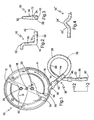
FIG. 1 is a fragmentary schematic overhead plan view of a mixing apparatus incorporating the features of the invention; -
FIG. 2 is a side elevational view of a pressure reducing apparatus taken along the line 2-2 ofFIG. 1 and in the direction indicated generally; -
FIG. 3 is a front elevational view of the apparatus ofFIG. 2 ; -
FIG. 4 is a fragmentary side elevational view of an alternate to the structure shown inFIG. 2 ; -
FIG. 5 is a fragmentary overhead plan view of a alternate embodiment of the apparatus ofFIG. 1 ; -
FIG. 6 is a fragmentary overhead plan view of another alternate embodiment of the apparatus ofFIG. 1 ; -
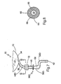
FIG. 7 is a fragmentary overhead plan view of a further alternate embodiment of the apparatus ofFIG. 1 ; andFIG. 8 is a section taken along the line 9-9 ofFIG. 7 and in the direction indicated generally. - Referring now to
FIG.1 , a mixing apparatus for mixing and dispensing a slurry is generally designated 10 and includes amixer 12 having a housing 14 configured for receiving and mixing the slurry. The housing 14 defines a mixingchamber 16 which is preferably generally cylindrical in shape, has a generallyvertical axis 18, and upperradial wall 20, a lower radial wall 22 and an annularperipheral wall 24. Aninlet 26 for calcined gypsum and aninlet 28 for water are both positioned the upperradial wall 20 proximate thevertical axis 18. It should be appreciated that theinlets chamber 16 by simple gravity feed. Also, as is well known in the art, other materials or additives in addition to gypsum and water, often employed in slurries to prepare gypsum products (e.g. accelerators, retarders, fillers, starch, binders, strengtheners, etc.) can also be supplied through these or other inlets similarly positioned. - An
agitator 30 is disposed in the mixingchamber 16 and has a generallyvertical drive shaft 32 positioned concentrically with thevertical axis 18 and extends through the upperradial wall 20. Theshaft 32 is connected to a conventional drive source such as a motor for rotating the shaft at whatever speed is appropriate for agitating theagitator 30 to mix the contents of the mixingchamber 16. Speeds in the range of 275-300 rpm are common. This rotation directs the resulting aqueous slurry in a generally centrifugal direction, such as in a counter-clockwise outward spiral indicated by the arrow A. It should be appreciated that this depiction of an agitator is relatively simplistic and meant only to indicate the basic principles of agitators commonly employed in gypsum slurry mixing chambers known in the art. Alternative agitator designs, including those employing pins or paddles, are contemplated. - An
outlet 34, also referred to as a mixer outlet, a discharge gate or a slot, is provided in theperipheral wall 24 for the discharge of the major portion of the well-mixed slurry into what is generally referred to herein as a mixing and dispensingapparatus 36. While conventional outlets are typically rectangular in cross-section, thepresent outlet 34 is preferably circular in cross-section, however other shapes are contemplated depending on the application. Also, while it is contemplated that the specific configuration of themixer 12 may vary, it is preferred that the present mixer is of the centrifugal type commonly used in the manufacture of gypsum wallboard, and also of the type in which theoutlet 34 dispenses the slurry tangentially to the housing 14. While conventional mixers typical provide a cutoff block at theoutlet 34 to mechanically adjust the flow of slurry for the desired thickness of wallboard, typically ranging from 0.6 to 3 cm (¼" to 1"), it has been found that such a block often provides a site for the premature setting of gypsum, resulting in slurry buildup and eventual clogging and disruption of the production line. - Another drawback of conventional cutoff blocks is that when the gate is set for thick wallboard and a conversion is made to thin wallboard, where the block is disposed to permit relatively free flow of slurry from the outlet, insufficient backpressure is provided in the mixing
chamber 16 which results in an incomplete and nonuniform mixing of slurry constituents. Also, inadequate backpressure results in dead spots or slow spots in the centrifugal internal flow in the mixingchamber 16, causing premature setup of the slurry and unwanted lumps in the mixture. In such instances, the wallboard line must be shut down for maintenance, causing inefficiencies in production. - The mixing and dispensing
apparatus 36 includes an elongate, preferably cylindrical tube orconduit 38 and having amain inlet 39 in slurry receiving communication with themixer outlet 34, and has anadditive inlet 40 such as a nipple for the introduction of aqueous foam or other desired additive, such as retarders, accelerators, dispersants, starch, binders, and strength-enhancing products such as poly- phosphates, typically sodium trimetaphosphate, all of which are known in the wallboard art, after the slurry has been substantially mixed. It is desired that when foam is the additive, it is uniformly mixed in the slurry but not excessively agitated to the extent that it is broken down. As such, it is common to introduce the foam into theadditive inlet 40 just after or downstream of, yet close to theoutlet 34 and themain inlet 39 to prolong mixing time with the slurry. However, depending on the particular application, it is contemplated that the additive such as foam may be introduced at other places along theapparatus 36. - It is preferred that the mixing and dispensing
apparatus 36 be in the range of at least 120 cm (48 inches), however it is contemplated that the length may vary depending on the particular application and the constraints of the particular gypsum wallboard production line. The extended length of the mixing and dispensingapparatus 36 is desirable for providing time for the foam to mix uniformly with the slurry after the point of additive introduction, and prior to dispensing the slurry upon a wallboard forming area such as the web of wallboard paper or upon a previously dispensed layer of relatively denser gypsum slurry, also deposited upon a web of wallboard paper. Since the preferred application for the present invention is a gypsum wallboard production line, the gypsum slurry with additives is commonly dispensed or discharged upon such a web. - A feature of the
present mixing Apparatus 10 is that theconduit 38 is placed in fluid communication with theoutlet 34 downstream from the introduction of foam at theinlet 40, and includes adischarge spout 42 for dispensing the slurry upon the web as described above. Theconduit 38 is preferably a flexible hose of rubber or rubber-like material (although rigid conduits are contemplated) and is of sufficient length to provide extra time for the foam or other additive to become more uniformly mixed within the slurry. While rigid conduits are also contemplated, best results have been obtained using hoses which are double reinforced to avoid kinking, preferably having a smooth inner surface, and being dimensioned in the range 3.75 - 7.5 cm (1½ -3 inches) inner diameter. Other diameters are contemplated to suit the application. In the present invention, a preferably relatively rigidadditive inlet portion 44 bearing theinlet nipple 40 is in the approximate range of 15-60 cm (6-24 inches), and with the preferablyflexible conduit 38, has a total length at least in the approximate range of 125 - 420 cm (50 to 168 inches) while longer lengths are contemplated, such as when increased slurry residence time is desired for more complete mixing. It is contemplated that in some applications, theadditive inlet portion 44 is also made of flexible, rubber-like material and is in the shape of a hose. When theadditive inlet portion 44 and theconduit 38 are made of dissimilar materials, they are joined to each other with adhesives, clamps, ultrasonic welding or other known fastening technologies in a way which will provide a smooth transition and which minimizes internal obstructions which might provide a site for the collection and premature setting of slurry. - As discussed above, another drawback of conventional gypsum slurry mixing apparatuses is that a canister is required downstream of the discharge gate to evenly mix the foam with the slurry and to reduce the slurry pressure . Another goal of the present invention is to eliminate the canister and its inherent problems. Accordingly, the present mixing and dispensing
apparatus 36 is configured to maintain a generally laminar flow of the slurry from themain inlet 39 to thedischarge spout 42 without a flow disrupter in the nature of the prior canisters. In the present invention, "laminar flow" is understood to mean a smooth, non-spiraling pipe flow that maintains full cross-sectional area of theconduit 38 through which it passes. This is in contrast to the turbulent flow of the prior canisters, in which uneven mixing of additives and slurry often occurred. - As will be described below, the flexibility of the present mixing and dispensing
apparatus 36, and specifically theconduit 38 permits coiled or serpentine configurations that extend the length of the mixingchamber 16, and thus increase the residence time in which the foam and/or other additive can completely mix with the slurry without requiring a longer production line. Unlike conventional wallboard mixing apparatuses, in the present invention theconduit 38 of the mixing and dispensingapparatus 36 is directly connected to thegate portion 44, and ultimately to theoutlet 34 without intervening devices such as a canister. Also, the preferably flexible construction of at least a portion of theconduit 38 reduces the tendency for gypsum to prematurely set up in the interior and cause undesirable clogging. - Another feature of the
present mixing apparatus 10 is at least oneflow restrictor 46 associated with the mixing and dispensingapparatus 36 for creating backpressure in the gate and ultimately in the mixingchamber 16, for controlling the flow of slurry from thespout 42 and for at least reducing and generally preventing the buildup of slurry in the gate and the mixer. In the preferred embodiment, therestrictor 46 is of the type which exerts an even, circular or concentric clamping force on theflexible conduit 38. Also, thepreferred restrictor 46 exerts its clamping force on the exterior of theconduit 38, so that an internal passageway of the conduit is not obstructed by valve components. - The
preferred restrictor 46 is a dynamically adjustable valve, i.e., is adjustable while themixer 12 is in operation and slurry is being emitted from thespout 42, and is taken from the group consisting of pinch valves, muscle valves, concentric valves, iris-action valves and butterfly valves. In some low-pressure applications, simple hose clamps are also suitable. It is contemplated to use a transition between a larger diameter hose to a smaller diameter hose section as therestrictor 46 for reducing the volume of dispensed slurry, and for creating backpressure. For best results, thevalve 46 is located on theconduit 38 near thespout 42 to provide the most efficient use of the length of the conduit for complete mixing of the foam into the slurry, however other locations farther from the spout are contemplated depending on the application. - Referring now to
FIGs. 1-3 , a further feature of thepresent mixing apparatus 10 is apressure reducing apparatus 50 in the mixing and dispensingapparatus 36 for reducing the pressure or force of the slurry being dispensed from thespout 42. Atypical mixer 12 of the type used with the present invention generates a slurry velocity in the approximate range of about 200-700 m/min (700-2200 ft/min), measured at the discharge gate oroutlet 34 with a corresponding force or pressure. Unless this force or pressure is reduced significantly, the force of me output of thespout 42 will disrupt the distribution of the previously deposited slurry, causing the above-described "washout", and will result in uneven wallboard. Thus, thepressure reducer 50 is needed so that the discharge from thespout 42 is acceptably slow and even. - In the preferred embodiment, the
pressure reducer 50 is disposed in close association with thespout 42 and generally defines a pair of right angle bends 52, 54 in theconduit 38. It is also contemplated that approximate right angles may be suitable in certain applications, such as where the mixer outlet pressure is relatively lower. Thepresent pressure reducer 50 is generally "S"-shaped when viewed from the side (the opposite side shown inFIG. 2 ). - The objective is to cause the flow of slurry in the
conduit 38 to undergo at least one and preferably at least two approximate right angle deflections prior to exiting thespout 42. Each successive right angle deflection will further reduce the output pressure of the slurry measured at thespout 42. It has also been found that positioning theconduit 38 to have an upwardly extending portion causes gravitational forces to reduce the pressure of the slurry. - Between the
right angle portions vertical transition leg 56. It has been found that slurry buildups between theportions transition leg 56 is more vertical. If thetransition leg 56 is oriented at more than a 10° angle from vertical, the potential for slurry buildup will increase. - As seen in
FIG. 3 , thespout 42 is slightly flared from the diameter of thehose 40. It is recommended that the diameter of thepressure reducer 50 is at least equivalent to the diameter of theconduit 38 to facilitate even slurry flow. In addition, sufficient brackets should be provided to support theconduit 38 as well as thepressure reducer 50 to prevent buildups and premature setting of slurry in the pressure reducer due to the resulting backpressure intentionally caused by this pressure reducer shape. - Referring now to
FIG. 4 , an alternate pressure reducer configuration is designated 50', and basically represents a structure where the angled portions 52' and 54' are greater than right angles to form a "hump" shape for reducing slurry flow pressure. - It is contemplated that the
pressure reducer 50 is made of a flexible polymeric material which is compatible with theconduit 38 and is securely and sealingly fastenable thereto by chemical adhesives, epoxy, sonic welding, heat staking or equivalent polymeric fastening technology. For best results, thepressure reducer 50 is located downstream of thevalve 46, with the valve between the pressure reducer and theoutlet 34, although other arrangements are contemplated depending on the application. - Referring now to
FIGs. 1 and5-8 , it will be seen that thepresent mixing apparatus 10 may be provided in a variety of mixing and dispensingapparatus 36 configurations, particularly in the arrangement and length of theconduit 38. In all of the embodiments described below, identical components are designated with corresponding reference numbers. Factors which influence the particular configuration of theconduit 38 employed include, among other things, the thickness of the wallboard being produced, the distance between themixer 12, themixer outlet 34 and the wallboard forming plate, and the particular characteristics of the slurry formulation, including the setting rate, the water/stucco ratio, glass fiber usage and the percentage of foam desired. Some of the present embodiments may be more successful than others, depending on the particular wallboard production line. - In all embodiments, it is preferred that any transitions or joints between hoses or components in the
interior passageway 58 of thegate portion 44, theconduit 38 and or thepressure reducer 50 should be smooth and minimize steps or obstructions which tend to encourage slurry buildup. Also, during operation, it has been found that periods of low slurry flow volume tend to increase the potential for slurry buildup, and this can be regulated by restricting or closing down thevalve 46, or using asmaller diameter conduit 38 and/oradditive inlet portion 44. - In
FIG. 1 , theadditive inlet portion 44 is relatively rigid and includes theinlet nipple 40. The flexible portion of theconduit 38 is secured to theadditive inlet portion 44 in a way which minimizes internal obstructions, as is known in the art, and forms aloop 60 to provide a satisfactory amount of time for mixing in the foam into the slurry in applications where length is at a premium on the wallboard forming table - between the
mixer 12, themixer outlet 34 and the board forming plate (not shown) of the wallboard forming area. - Referring now to
FIG. 5 , the apparatus is generally designated 36a, features a curved gate portion 44a, and foam is introduced through an injection ring or block 64 (best seen inFIGs. 7 and 8 ). A plurality and preferably three foam injection ports 66 (best seen inFIG. 8 ) are employed for injecting foam into the mainslurry flow passageway 58. Apressure sensor 70 is used to trigger thepinch valve 46, which is contemplated as being automatically or manually adjustable while theapparatus 10 is dispensing slurry. A widemouthed bell formation 72 may be used to reduce slurry pressure, either alone or in conjunction with the pressure reducer 50 (FIG. 2 ). - Referring now to
FIG. 6 , a variation of the configuration ofFIG. 1 is shown, and the apparatus is generally designated 36b, which features a conduit 38b fashioned into a zig-zag or "S"-shape when viewed from above. Note that in this embodiment, thespout 42 is approximately equidistant from anend 74 of the gate portion 44b. An advantage of the configuration of the conduit 38b over theconduit 38 is that additional length can be provided in a shorter distance from themixer 12, which is useful in board lines in which space is at a premium. Also, in this embodiment it will be appreciated that thespout 42 is vertically displaced below the gate portion 44b and also below amain leg 76 of the conduit 38b. In developing space-saving configurations for theconduits 38, 38a, 38b, etc., care must be taken to avoid creating kinks which can cause flow disruptions or collect slurry and cause premature setting and clogging. - Referring now to
FIGs. 7 and 8 , a mixing and dispensing apparatus 36d having a conduit 38d is shown with a relatively flexible gate portion 44d, feeding into thefoam injection block 64 and then into thepressure sensor 70 and theconcentric valve 46. A feature of the mixing and dispensing apparatus 36d is that the pressure reducer 50d, in defining its "S"-shape, has both a vertical and a horizontal displacement from thevalve 46. - In all of the embodiments, to ensure that slurry buildups are not occurring, it is recommended that operators periodically squeeze the
conduit 38 and/or thespout 42, such as every 15 minutes or so. - In operation, it will be seen that a system for providing an evenly mixed slurry to a web is provided, including inserting calcined gypsum and water into the mixing
chamber 16 through one ormore inlets outlet 34 of themixer 12, passing the agitated contents into themain inlet 39 of the mixing and dispensingapparatus 36, 36a, 36b, 36d introducing an aqueous foam into the mixture at the gate, preferably through theinlet nipple 40, creating a backpressure on the mixture in the gate by constricting the area of mixture being emitted from theflexible conduit 38, 38a, 38b, 38d of the gate, the backpressure being created by constricting theconduit 38, such as with thevalve 46, and controlling the pressure of slurry and additive dispensed from thespout 42 such as by thepressure reducer 50 in its various configurations. In the preferred embodiment, the slurry pressure is reduced by being forced to change direction approximately 90° at least once and preferably twice. - Where possible, the
flexible conduit 38 extends generally directly down the board line. The longer theconduit 38, the more even is the mixing of the foam with the slurry. It is contemplated that theconduit 38 may extend linearly at least as much as 150cm (60 inches) past themixer 12. For board line applications where there is insufficient space before the forming plate is encountered, a set-up recommended. The benefits of improved foam/slurry mixing achieved by the present invention include: reduction and/or elimination of blisters in the board; uniformity of the board, leading to improved strength; and potential water reduction from the board formulation, which in turn will led to energy savings in the kiln or an increase in line speed. - While specific embodiments of the slurry mixer outlet of the present invention have been shown and described, it will be appreciated by those skilled in the art that changes and modifications may be made thereto without departing from the invention as set forth in the following claims.
Claims (20)
- An apparatus (36) for delivering an additive-enhanced slurry for use in making gypsum wallboard, comprising:a conduit (38) having a main inlet (39) for introducing slurry from a centrifugal mixer and a spout (42) for discharging the slurry; and further comprisingat least one flow restrictor (46) associated with said conduit (38) for creating back pressure between said flow restrictor (46) and the main inlet (39); andat least one pressure reducer (50) associated with said discharge spout (42) and configured for reducing the pressure of the slurry dispensed from said discharge spout (42),wherein said apparatus is configured for maintaining a generally laminar flow from the mixer outlet (34) to said discharge spout (42).
- The apparatus of claim 1 wherein said conduit (38) has at least one inlet (40) between said main inlet (39) and said discharge spout (42) for receiving at least one additive.
- The apparatus of claim 2 wherein said conduit (38) has a length of at least approximately 120 cm (48 inches).
- The apparatus of claim 2 wherein said conduit (38) is flexible and can be curved.
- The apparatus of claim 1 wherein said at least one flow restrictor (46) is at least one dynamically adjustable valve configured for creating back pressure between said flow restrictor (46) and said main inlet (39) for controlling the flow of slurry from said spout (42) and for reducing buildup of slurry in said apparatus.
- The apparatus of claim 5 wherein said at least one valve (46) is taken from the group consisting of pinch valves, muscle valves, concentric valves, iris-action valves, hose clamps and butterfly valves.
- The apparatus of claim 1 wherein said pressure reducing apparatus (50) generally defines a pair of approximate right-angle bends in said conduit (38).
- The apparatus of claim 7 wherein said pressure reducing apparatus (50) is "S"-shaped.
- The apparatus of claim 7 wherein said pressure reducing apparatus (50) is "C"-shaped.
- The apparatus of claim 1 wherein said conduit (38) is bifurcated near said spout (42).
- The apparatus of claim 1 wherein said conduit (38) is a hose.
- The apparatus of claim 1 wherein said pressure reducer (50) is disposed between the flow restrictor (46) and the discharge spout (42).
- A wallboard manufacturing system with a mixing apparatus for mixing and dispensing a slurry onto a wallboard forming surface, comprising:a centrifugal mixer (12) having a housing configured for receiving and mixing slurry components, having a discharge outlet (34) at a tangent to said housing;a conduit (38) in fluid communication with said outlet (34) and having a spout (42) for discharging the slurry;at least one flow restrictor (46) on said conduit (38) for restricting the volume of the slurry dispensed from said spout (42); andat least one pressure reducer (50) associated with said spout (42) and configured for reducing the pressure of the slurry dispensed from said spout (42);said conduit (38) being configured to maintain laminar flow of the slurry from said outlet (34) to said spout (42).
- The wallboard manufacturing system of claim 13 wherein at least a portion of said conduit (38) is a flexible hose.
- The wallboard manufacturing system of claim 13 wherein said at least one flow restrictor (46) is at least one dynamically adjustable valve.
- The wallboard manufacturing system of claim 13 wherein said conduit (38) wraps at least partially around the mixer (12).
- The wallboard manufacturing system of claim 13 wherein said conduit (38) includes an additive inlet portion (44) in fluid communication with said outlet (34), and has at least one inlet (40) for receiving at least one additive.
- A method for providing an evenly mixed additive enhanced slurry to a web, comprising:inserting calcined gypsum and water into a mixing chamber of a mixer through one or more inlet of the mixing chamber;agitating the contents of the mixing chamber to form an aqueous dispersion of the calcined gypsum; passing the agitated contents from an outlet of the mixer into a slurry dispensing apparatus including a conduit (38);introducing an additive into the mixture in the slurry dispensing apparatus and mixing the additive with the slurry;creating a back-pressure on the mixture in the dispensing apparatus by reducing the volume of mixture being emitted from the conduit (38),said backpressure being created by constricting the conduit; andcontrolling the pressure of the additive enhanced slurry dispensed from a spout (42) of the conduit (38).
- The method of claim 18 wherein said pressure is controlled by causing said mixture to change flow direction approximately 90° at least one time.
- The method of claim 18 wherein said agitated contents are passed directly from said mixer outlet, through said conduit and out the spout in a way that maintains laminar flow.
Applications Claiming Priority (3)
| Application Number | Priority Date | Filing Date | Title |
|---|---|---|---|
| US905553 | 1986-09-09 | ||
| US09/905,553 US6494609B1 (en) | 2001-07-16 | 2001-07-16 | Slurry mixer outlet |
| PCT/US2002/021263 WO2003008167A1 (en) | 2001-07-16 | 2002-07-03 | Apparatus and method for mixing and dispensing an additive-enhanced slurry |
Publications (2)
| Publication Number | Publication Date |
|---|---|
| EP1417081A1 EP1417081A1 (en) | 2004-05-12 |
| EP1417081B1 true EP1417081B1 (en) | 2010-11-10 |
Family
ID=25421034
Family Applications (1)
| Application Number | Title | Priority Date | Filing Date |
|---|---|---|---|
| EP02744828A Expired - Lifetime EP1417081B1 (en) | 2001-07-16 | 2002-07-03 | Apparatus and method for mixing and dispensing an additive-enhanced slurry |
Country Status (8)
| Country | Link |
|---|---|
| US (2) | US6494609B1 (en) |
| EP (1) | EP1417081B1 (en) |
| AU (1) | AU2002346070B2 (en) |
| CA (1) | CA2446672C (en) |
| DE (1) | DE60238259D1 (en) |
| MX (1) | MXPA03011139A (en) |
| NZ (1) | NZ529470A (en) |
| WO (1) | WO2003008167A1 (en) |
Cited By (1)
| Publication number | Priority date | Publication date | Assignee | Title |
|---|---|---|---|---|
| CN105873734A (en) * | 2013-09-30 | 2016-08-17 | 美国石膏公司 | Systems and methods for controlling a conveyor system during product changeovers |
Families Citing this family (148)
| Publication number | Priority date | Publication date | Assignee | Title |
|---|---|---|---|---|
| US6494609B1 (en) * | 2001-07-16 | 2002-12-17 | United States Gypsum Company | Slurry mixer outlet |
| CN100478152C (en) | 2002-09-20 | 2009-04-15 | 吉野石膏株式会社 | Apparatus and method for fractionating slurry and method of producing plasterboard |
| GB0223875D0 (en) * | 2002-10-15 | 2002-11-20 | Bpb Plc | Method and apparatus for producing a multilayer cementitious product |
| CL2004000569A1 (en) * | 2003-03-19 | 2005-05-06 | United States Gypsum Co | METHODS TO PREPARE ACOUSTIC PANELS FROM A MIXTURE THAT INCLUDES WATER, FOAMING AGENT, CALCINATED PLASTER, AND OPTIONALLY ADDITIVES; AND ACOUSTIC PANELS. |
| EP1637302B1 (en) * | 2003-05-26 | 2011-07-13 | Yoshino Gypsum Co., Ltd. | Mixers, mixing methods, and use of said mixers for producing gypsum board |
| US7007914B2 (en) * | 2004-05-14 | 2006-03-07 | United States Gypsum Company | Slurry mixer constrictor valve |
| RU2373170C2 (en) * | 2005-04-27 | 2009-11-20 | Юнайтед Стэйтс Джипсум Компани | Methods and systems for production of heat resistant accelerant suspension and addition of accelerant suspension into aqueous dispersion of calcined gypsum after mixer |
| CN101189195A (en) * | 2005-04-27 | 2008-05-28 | 美国石膏公司 | Method and system for preparing heat resistant accelerator slurry and adding accelerator slurry to mixed aqueous dispersion of calcined gypsum |
| NZ561843A (en) * | 2005-04-27 | 2011-02-25 | United States Gypsum Co | Adding a production additive to an aqueous dispersion of calcined gypsum with the ratio of viscosity between the two is between 10:1 to 2:1 |
| US20060243171A1 (en) * | 2005-04-27 | 2006-11-02 | United States Gypsum Company | Wet gypsum accelerator and methods, composition, and product relating thereto |
| US8016960B2 (en) * | 2005-04-27 | 2011-09-13 | United States Gypsum Company | Methods of and systems for adding a high viscosity gypsum additive to a post-mixer aqueous dispersion of calcined gypsum |
| US7718019B2 (en) * | 2005-04-27 | 2010-05-18 | United States Gypsum Company | Methods of and systems for preparing a heat resistant accelerant slurry and adding the accelerant slurry to a post-mixer aqueous dispersion of calcined gypsum |
| US9802866B2 (en) | 2005-06-09 | 2017-10-31 | United States Gypsum Company | Light weight gypsum board |
| US11338548B2 (en) | 2005-06-09 | 2022-05-24 | United States Gypsum Company | Light weight gypsum board |
| US9840066B2 (en) | 2005-06-09 | 2017-12-12 | United States Gypsum Company | Light weight gypsum board |
| US11306028B2 (en) | 2005-06-09 | 2022-04-19 | United States Gypsum Company | Light weight gypsum board |
| US7364676B2 (en) * | 2005-09-01 | 2008-04-29 | United States Gypsum Company | Slurry spreader for cementitious board production |
| US8262820B2 (en) * | 2006-04-28 | 2012-09-11 | United States Gypsum Company | Method of water dispersing pregelatinized starch in making gypsum products |
| US8066421B2 (en) * | 2007-07-03 | 2011-11-29 | National Gypsum Properties, Llc | Method of adding STMP to a gypsum slurry |
| US7524386B2 (en) | 2006-11-01 | 2009-04-28 | United States Gypsum Company | Method for wet mixing cementitious slurry for fiber-reinforced structural cement panels |
| US7513963B2 (en) * | 2006-11-01 | 2009-04-07 | United States Gypsum Company | Method for wet mixing cementitious slurry for fiber-reinforced structural cement panels |
| US7754052B2 (en) * | 2006-11-01 | 2010-07-13 | United States Gypsum Company | Process and apparatus for feeding cementitious slurry for fiber-reinforced structural cement panels |
| US7475599B2 (en) * | 2006-11-01 | 2009-01-13 | United States Gypsum Company | Wet slurry thickness gauge and method for use of same |
| US20080099133A1 (en) * | 2006-11-01 | 2008-05-01 | United States Gypsum Company | Panel smoothing process and apparatus for forming a smooth continuous surface on fiber-reinforced structural cement panels |
| US20080179775A1 (en) * | 2007-01-31 | 2008-07-31 | Usg Interiors, Inc. | Transfer Plate Useful in the Manufacture of Panel and Board Products |
| US8070895B2 (en) | 2007-02-12 | 2011-12-06 | United States Gypsum Company | Water resistant cementitious article and method for preparing same |
| DE102008045820A1 (en) * | 2008-09-05 | 2010-04-08 | Axel Wittek | Transition elements for passing a dispersion in the treatment in a rotor-stator dispersing machine |
| US8047009B2 (en) | 2008-12-09 | 2011-11-01 | Tire Seal, Inc. | Method and apparatus for providing additive fluids to refrigerant circuit |
| US8329308B2 (en) | 2009-03-31 | 2012-12-11 | United States Gypsum Company | Cementitious article and method for preparing the same |
| FR2955286B1 (en) * | 2010-01-20 | 2017-03-24 | Lafarge Gypsum Int | MIXER FOR PLASTER PASTE |
| JP2014508665A (en) | 2010-12-29 | 2014-04-10 | ユナイテッド・ステイツ・ジプサム・カンパニー | How to improve gypsum board strength |
| MX356602B (en) | 2010-12-30 | 2018-06-05 | United States Gypsum Co | Slurry distributor, system and method for using same. |
| WO2012092534A1 (en) | 2010-12-30 | 2012-07-05 | United States Gypsum Company | Slurry distribution system and method |
| US9296124B2 (en) | 2010-12-30 | 2016-03-29 | United States Gypsum Company | Slurry distributor with a wiping mechanism, system, and method for using same |
| US10076853B2 (en) | 2010-12-30 | 2018-09-18 | United States Gypsum Company | Slurry distributor, system, and method for using same |
| US9999989B2 (en) | 2010-12-30 | 2018-06-19 | United States Gypsum Company | Slurry distributor with a profiling mechanism, system, and method for using same |
| US8475762B2 (en) * | 2011-06-02 | 2013-07-02 | United States Gypsum Company | Method and apparatus to minimize air-slurry separation during gypsum slurry flow |
| HRP20200296T8 (en) | 2011-10-24 | 2020-08-07 | United States Gypsum Company | Flow splitter for slurry distribution system |
| ES2606019T3 (en) * | 2011-10-24 | 2017-03-17 | United States Gypsum Company | Discharge splice with multiple branches for grout distribution |
| CA2851533C (en) | 2011-10-24 | 2020-01-14 | United States Gypsum Company | Multi-piece mold and method of making slurry distributor |
| MX2014009534A (en) | 2012-02-17 | 2014-10-13 | United States Gypsum Co | Gypsum products with high efficiency heat sink additives. |
| US10399899B2 (en) | 2012-10-23 | 2019-09-03 | United States Gypsum Company | Pregelatinized starch with mid-range viscosity, and product, slurry and methods related thereto |
| US9828441B2 (en) | 2012-10-23 | 2017-11-28 | United States Gypsum Company | Method of preparing pregelatinized, partially hydrolyzed starch and related methods and products |
| US9540810B2 (en) | 2012-10-23 | 2017-01-10 | United States Gypsum Company | Pregelatinized starch with mid-range viscosity, and product, slurry and methods related thereto |
| WO2014066207A1 (en) * | 2012-10-24 | 2014-05-01 | United States Gypsum Company | Slurry distributor, system, and method for using same |
| PE20151111A1 (en) | 2012-10-24 | 2015-08-30 | United States Gypsum Co | GROUT DISTRIBUTOR WITH A PROFILING MECHANISM, SYSTEM, AND SAME USE METHOD |
| AU2013334839B2 (en) | 2012-10-24 | 2017-07-13 | United States Gypsum Company | Slurry distributor with a wiping mechanism, system, and method for using same |
| CA2892024C (en) | 2012-12-05 | 2021-01-19 | Yoshino Gypsum Co., Ltd. | Mixing and stirring device, mixing and stirring method, and method for manufacturing lightweight gypsum board |
| US9540287B2 (en) | 2013-03-13 | 2017-01-10 | United States Gypsum Company | Particle stabilized foam, and slurries, product, and methods related thereto |
| US20140261954A1 (en) | 2013-03-15 | 2014-09-18 | United States Gypsum Company | Method of preparing mat-faced article |
| US10336036B2 (en) | 2013-03-15 | 2019-07-02 | United States Gypsum Company | Cementitious article comprising hydrophobic finish |
| AU2014329817B9 (en) | 2013-10-02 | 2019-01-03 | United States Gypsum Company | Method of preparing pregelatinized, partially hydrolyzed starch and related methods and products |
| JP6322353B2 (en) | 2013-12-17 | 2018-05-09 | 吉野石膏株式会社 | Mixing stirrer, mixing stirring method, and lightweight gypsum board manufacturing method |
| US10189180B2 (en) | 2014-01-15 | 2019-01-29 | United States Gypsum Company | Foam injection system with variable port inserts for slurry mixing and dispensing apparatus |
| US10059033B2 (en) * | 2014-02-18 | 2018-08-28 | United States Gypsum Company | Cementitious slurry mixing and dispensing system with pulser assembly and method for using same |
| US9821281B2 (en) | 2014-04-18 | 2017-11-21 | United States Gypsum Company | Eductor based mixer for mixing stucco and water |
| US10011045B2 (en) | 2014-05-19 | 2018-07-03 | United States Gypsum Company | Slurry mixer gate with enhanced flow and foaming geometry |
| US9694332B2 (en) | 2014-10-30 | 2017-07-04 | United States Gypsum Company | Slurry mixer discharge gate adapter with transitioning cross-sectional geometry |
| US10155692B2 (en) | 2015-03-13 | 2018-12-18 | United States Gypsum Company | Hydrophobic finish compositions with extended flow time retention and building products made thereof |
| US10569237B2 (en) * | 2015-04-30 | 2020-02-25 | Continental Building Products Operating Company, LLC | Baffled donut apparatus for use in system and method for forming gypsum board |
| US10309771B2 (en) | 2015-06-11 | 2019-06-04 | United States Gypsum Company | System and method for determining facer surface smoothness |
| WO2016209942A1 (en) | 2015-06-24 | 2016-12-29 | United States Gypsum Company | Composite gypsum board and methods related thereto |
| US10421251B2 (en) | 2015-06-24 | 2019-09-24 | United States Gypsum Company | Composite gypsum board and methods related thereto |
| US9745222B2 (en) | 2015-07-23 | 2017-08-29 | United States Gypsum Company | Apparatus and methods for producing gypsum wallboard |
| US10620052B2 (en) | 2015-08-10 | 2020-04-14 | United States Gypsum Company | System and method for manufacturing cementitious boards with on-line void detection |
| US9700861B2 (en) | 2015-09-04 | 2017-07-11 | United States Gypsum Company | Slurry mixer gate having enhanced extractor ports |
| US10407344B2 (en) | 2015-10-01 | 2019-09-10 | United States Gypsum Company | Foam modifiers for gypsum slurries, methods, and products |
| WO2017058316A1 (en) | 2015-10-01 | 2017-04-06 | United States Gypsum Company | Foam modifiers for cementitious slurries, methods, and products |
| US10662112B2 (en) | 2015-10-01 | 2020-05-26 | United States Gypsum Company | Method and system for on-line blending of foaming agent with foam modifier for addition to cementitious slurries |
| US9964942B2 (en) | 2015-11-05 | 2018-05-08 | United States Gypsum Company | System and method for manufacturing cementitious boards with on-line board measurement |
| US10537863B2 (en) | 2015-12-31 | 2020-01-21 | United States Gypsum Company | Constrictor valve with webbing, cementitious slurry mixing and dispensing assembly, and method for making cementitious product |
| US10207475B2 (en) | 2016-05-13 | 2019-02-19 | United States Gypsum Company | Mat-faced board |
| WO2017196644A1 (en) | 2016-05-13 | 2017-11-16 | United States Gypsum Company | Mat-faced board and method for producing board |
| US10677698B2 (en) | 2016-06-15 | 2020-06-09 | United States Gypsum Company | System and method for manufacturing cementitious boards with on-line slurry set measurement |
| PE20190239A1 (en) | 2016-06-17 | 2019-02-20 | United States Gypsum Co | METHOD AND SYSTEM FOR IN-LINE MIXING OF FOAMING AGENT WITH FOAM MODIFIER FOR THE ADDITION OF CEMENTARY GROUTS |
| US9945119B2 (en) | 2016-07-28 | 2018-04-17 | United States Gypsum Company | Methods for making gypsum boards with polymer coating and gypsum boards made by the method |
| US11225046B2 (en) | 2016-09-08 | 2022-01-18 | United States Gypsum Company | Gypsum board with perforated cover sheet and system and method for manufacturing same |
| US20180080226A1 (en) | 2016-09-22 | 2018-03-22 | United States Gypsum Company | Gypsum boards with polymer coating and methods for making same |
| US10604929B2 (en) | 2016-11-01 | 2020-03-31 | United States Gypsum Company | Fire resistant gypsum board comprising expandable graphite and related methods and slurries |
| US10564081B2 (en) | 2017-02-03 | 2020-02-18 | United States Gypsum Company | System and method for evaluating edge hardness of cementitious boards and system for stacking cementitious boards inlcuding same |
| US10717059B2 (en) | 2017-05-18 | 2020-07-21 | United States Gypsum Company | Calcined gypsum slurry mixing apparatus having variably positionable lump ring and method for manufacturing gypsum product using same |
| US10774473B2 (en) | 2017-05-26 | 2020-09-15 | United States Gypsum Company | Compositions and methods with microfibrillated cellulose for wallboard paper |
| US10919808B2 (en) | 2017-07-18 | 2021-02-16 | United States Gypsum Company | Gypsum composition comprising uncooked starch having mid-range viscosity, and methods and products related thereto |
| US11008257B2 (en) | 2017-07-18 | 2021-05-18 | United States Gypsum Company | Gypsum composition comprising uncooked starch having mid-range viscosity, and methods and products related thereto |
| US20190062215A1 (en) | 2017-08-25 | 2019-02-28 | United States Gypsum Company | Gypsum board with enhanced strength, and related methods, slurries, and cover sheets |
| RU2757243C1 (en) * | 2017-09-19 | 2021-10-12 | Йосино Джипсум Ко., Лтд. | Mixer channel for feeding gypsum suspension and method for feeding gypsum suspension |
| US20190092689A1 (en) | 2017-09-26 | 2019-03-28 | United States Gypsum Company | Migrating starch with high cold-water solubility for use in preparing gypsum board |
| US10752558B2 (en) | 2017-11-20 | 2020-08-25 | Continental Building Products Operating Company, LLC | System and method for utilizing canister and hose to move slurry mixture to make gypsum board |
| US11834374B2 (en) | 2018-04-19 | 2023-12-05 | United States Gypsum Company | Accelerator comprising starch, and related board, slurries, and methods |
| US10988416B2 (en) | 2018-04-23 | 2021-04-27 | United States Gypsum Company | Colloidal vesicles for use as dedusting agents in construction panels |
| US20190329448A1 (en) | 2018-04-25 | 2019-10-31 | United States Gypsum Company | System and method for manufacturing gypsum boards with online lump detection |
| US11002010B2 (en) | 2018-05-01 | 2021-05-11 | United States Gypsum Company | Methods for making high sound transmission class gypsum boards and gypsum boards made by the method |
| US11584690B2 (en) | 2018-05-21 | 2023-02-21 | United States Gypsum Company | Multi-layer gypsum board and related methods and slurries |
| US20190352232A1 (en) | 2018-05-21 | 2019-11-21 | United States Gypsum Company | Multi-layer gypsum board and related methods and slurries |
| US11186067B2 (en) | 2018-08-14 | 2021-11-30 | United States Gypsum Company | Gypsum board from gypsum having high level of chloride salt and a starch layer and methods associated therewith |
| US11186066B2 (en) | 2018-08-14 | 2021-11-30 | United States Gypsum Company | Gypsum board from gypsum having high level of chloride salt and a perforated sheet and methods associated therewith |
| US11518141B2 (en) | 2018-11-01 | 2022-12-06 | United States Gypsum Company | Water barrier exterior sheathing panel |
| CN109624060B (en) * | 2018-12-07 | 2021-07-13 | 嘉善嘉诚混凝土制管有限公司 | A concrete pouring device |
| US11046053B2 (en) | 2019-02-15 | 2021-06-29 | United States Gypsum Company | Composite gypsum board and related methods |
| US11702373B2 (en) | 2019-06-17 | 2023-07-18 | United States Gypsum Company | Gypsum wallboard with enhanced fire resistance, and related coatings and methods |
| CN110341041B (en) * | 2019-07-12 | 2021-05-04 | 张卓群 | A kind of mixing and stirring device for construction |
| US11702839B2 (en) | 2019-08-20 | 2023-07-18 | United States Gypsum Company | Missile impact resistant exterior sheathing building panel |
| CN110788998A (en) * | 2019-10-24 | 2020-02-14 | 长沙爱达环保科技有限公司 | Novel discharge apparatus and mixing station using same |
| US11407145B2 (en) | 2019-10-28 | 2022-08-09 | United States Gypsum Company | Gypsum slurry mixer output canister |
| US11993054B2 (en) | 2019-11-05 | 2024-05-28 | United States Gypsum Company | Method of preparing gypsum wallboard from high salt gypsum, and related product |
| US11787739B2 (en) | 2019-11-22 | 2023-10-17 | United States Gypsum Company | Flour binder for gypsum board, and related methods, product, and slurries |
| US11891336B2 (en) | 2019-11-22 | 2024-02-06 | United States Gypsum Company | Gypsum board containing high absorption paper and related methods |
| ES2990252T3 (en) * | 2019-12-10 | 2024-11-29 | Saint Gobain Placo | Hose |
| US20210198148A1 (en) | 2019-12-26 | 2021-07-01 | United States Gypsum Company | Composite gypsum board formed from high-salt stucco and related methods |
| US11834375B2 (en) | 2020-01-31 | 2023-12-05 | United States Gypsum Company | Fire resistant gypsum board and related methods |
| US11344854B2 (en) | 2020-03-12 | 2022-05-31 | Knauf Gips Kg | Mixer rotor pin with hole |
| US20210299999A1 (en) | 2020-03-31 | 2021-09-30 | United States Gypsum Company | Glass-mat tile backer panel and manufacturing process of a glass-mat tile backer panel |
| US12281045B2 (en) | 2020-04-28 | 2025-04-22 | Knauf Gips Kg | Methods for reclaiming gypsum panels that contain hydrophobic materials and use thereof |
| CN111761727A (en) * | 2020-07-17 | 2020-10-13 | 广州易鑫建筑工程有限公司 | A concrete mixing device for bridge construction |
| CA3204020A1 (en) | 2021-01-13 | 2022-07-21 | Yijun SANG | Open-celled gypsum core, gypsum acoustic panel, and method for making same |
| US12304871B2 (en) | 2021-01-13 | 2025-05-20 | Knauf Gips Kg | Open-celled gypsum core, gypsum acoustic panel, and method for making same |
| MX2023011795A (en) | 2021-05-07 | 2023-10-12 | Knauf Gips Kg | High temperature sag resistant lightweight gypsum board. |
| US12612334B2 (en) | 2021-06-23 | 2026-04-28 | Knauf Gips Kg | Gypsum wallboard having multiple blended surfactants |
| US20230002974A1 (en) | 2021-07-02 | 2023-01-05 | Knauf Gips Kg | Compositions and methods for making paper using uncooked starch for gypsum panels |
| US12415765B2 (en) | 2021-07-09 | 2025-09-16 | Knauf Gips Kg | Board with fiber-reinforced dense layer |
| US12448334B2 (en) | 2021-07-23 | 2025-10-21 | Knauf Gips Kg | High temperature sag resistant gypsum panel |
| WO2023044403A1 (en) | 2021-09-17 | 2023-03-23 | United States Gypsum Company | System and method for manufacturing calcined gypsum with in-line calcination control device |
| US11999658B2 (en) | 2021-11-16 | 2024-06-04 | United States Gypsum Company | High salt gypsum wallboard containing salt absorbents and methods of making same |
| WO2023091880A1 (en) | 2021-11-16 | 2023-05-25 | United States Gypsum Company | High salt gypsum wallboard containing salt absorbents and methods of making same |
| CA3251658A1 (en) | 2022-02-08 | 2023-08-17 | Knauf Gips Kg | Gypsum panel containing ammonium-exchanged vermiculite and methods |
| US12448328B2 (en) | 2022-02-08 | 2025-10-21 | Knauf Gips Kg | Gypsum panel containing ammonium-exchanged vermiculite and methods |
| US12564984B2 (en) | 2022-03-15 | 2026-03-03 | Knauf Gips Kg | Wallboard slurry mixer configured for reducing water:stucco ratio |
| US12297151B2 (en) | 2022-05-04 | 2025-05-13 | Knauf Gips Kg | Gypsum board from gypsum having high level of chloride salt and a polymer layer and methods associated therewith |
| IL316977A (en) | 2022-06-16 | 2025-01-01 | Knauf Gips Kg | Gypsum slurry mixer process for enhanced wallboard strength |
| US20230406781A1 (en) * | 2022-06-16 | 2023-12-21 | United States Gypsum Company | Gypsum slurry mixer process for enhanced wallboard strength |
| WO2024026264A1 (en) | 2022-07-29 | 2024-02-01 | United States Gypsum Company | Method and apparatus for making a gypsum board, and gypsum board made according to the method |
| US12558811B2 (en) | 2022-07-29 | 2026-02-24 | Knauf Gips Kg | Method and apparatus for making a gypsum board |
| CA3268007A1 (en) | 2022-09-27 | 2024-04-04 | Knauf Gips Kg | A method for measuring width and edge profile of a single board in a stack of multiple boards |
| EP4357093A1 (en) * | 2022-10-20 | 2024-04-24 | Saint-Gobain Placo | Apparatus and method for manufacturing cementitious slurry comprising foam, and channel for such apparatus |
| EP4357096A1 (en) * | 2022-10-20 | 2024-04-24 | Saint-Gobain Placo | Apparatus and method for manufacturing cementitious slurry comprising foam, and channel for such apparatus |
| EP4357094A1 (en) * | 2022-10-20 | 2024-04-24 | Saint-Gobain Placo | Apparatus and method for manufacturing cementitious slurry comprising foam |
| WO2024118429A1 (en) | 2022-12-01 | 2024-06-06 | United States Gypsum Company | Coated gypsum set stabilizing particles having a hydrophobic gypsum core, gypsum board including same, process for making the particles, and processfor making the gypsum board |
| EP4643085A1 (en) | 2023-01-26 | 2025-11-05 | Knauf Gips KG | Non-contact encoder for board measurement |
| US20250002420A1 (en) | 2023-06-30 | 2025-01-02 | Usg Interiors, Llc | Alkali metal polyborate silicate coating for acoustical panel and gypsum board |
| EP4743274A1 (en) | 2023-07-10 | 2026-05-20 | Knauf Gips Kg | METHOD AND DEVICE FOR PRODUCE A PLASTER BOARD |
| IL326534A (en) | 2023-09-01 | 2026-04-01 | Knauf Gips Kg | Gypsum boards prepared using eco-friendly dispersants and related slurries and methods |
| WO2025064299A1 (en) | 2023-09-19 | 2025-03-27 | United States Gypsum Company | Gypsum boards prepared using uncalcined gypsum and slurries and methods related thereto |
| WO2025072074A1 (en) | 2023-09-28 | 2025-04-03 | United States Gypsum Company | Fire resistant gypsum board comprising silica fume and related methods |
| US12617123B2 (en) | 2023-11-29 | 2026-05-05 | Knauf Gips Kg | Slurry roller conveyor for gypsum board manufacture |
| WO2025117346A1 (en) | 2023-11-29 | 2025-06-05 | United States Gypsum Company | Slurry roller conveyor for gypsum board manufacture |
| WO2025136879A2 (en) | 2023-12-20 | 2025-06-26 | United States Gypsum Company | Methods of preparing gypsum board using cellulosic fiber |
| US20260070846A1 (en) | 2024-08-21 | 2026-03-12 | United States Gypsum Company | Green gypsum board prepared using low water to solids ratio |
| CN119550473B (en) * | 2025-01-24 | 2026-01-27 | 中国电建集团西北勘测设计研究院有限公司 | Fiber concrete stirring device and stirring method |
Family Cites Families (26)
| Publication number | Priority date | Publication date | Assignee | Title |
|---|---|---|---|---|
| US1500452A (en) | 1922-06-02 | 1924-07-08 | Universal Gypsum Company | Plaster wall board |
| US2207339A (en) | 1936-06-20 | 1940-07-09 | United States Gypsum Co | Gypsum composition |
| US2253059A (en) * | 1939-09-20 | 1941-08-19 | United States Gypsum Co | Mixer |
| US2985219A (en) | 1958-12-29 | 1961-05-23 | United States Gypsum Co | Process and apparatus for producing plasterboard |
| US3173663A (en) * | 1963-06-03 | 1965-03-16 | Monolith Portland Cement Compa | Material movement |
| US3343818A (en) | 1966-06-14 | 1967-09-26 | Nat Gypsum Co | Process for making gypsum board |
| US4009062A (en) | 1974-07-23 | 1977-02-22 | United States Gypsum Company | Gypsum wallboard -- making process and product |
| US4334786A (en) | 1978-02-08 | 1982-06-15 | Saint Gobain Industries | Process and mechanism for evolutive pulp flow regulation |
| US4176972A (en) * | 1978-08-09 | 1979-12-04 | National Gypsum Company | Coaxial pump mixer |
| US4184771A (en) * | 1978-08-24 | 1980-01-22 | Geosource Inc. | Centrifugal mud mixer |
| US4279673A (en) | 1980-02-11 | 1981-07-21 | National Gypsum Company | Hard-edge wallboard |
| US4354885A (en) | 1981-06-15 | 1982-10-19 | National Gypsum Company | Hard-edge wallboard |
| DE3401397C2 (en) * | 1984-01-17 | 1986-09-11 | MTU Motoren- und Turbinen-Union München GmbH, 8000 München | Device for compensating pressure and flow fluctuations in liquid supply systems for machines, in particular fuel supply systems for gas turbine engines |
| US4812045A (en) * | 1987-08-20 | 1989-03-14 | Domtar Gypsum Inc. | Gypsum dissolution system |
| US4820053A (en) * | 1987-08-20 | 1989-04-11 | Domtar Gypsum Inc. | Gypsum dissolution system |
| DE3865603D1 (en) * | 1987-09-02 | 1991-11-21 | Babcock Bsh Ag | MIXER FOR THE PRODUCTION OF MORTAR FROM FINE GRAIN BINDERS, IN PARTICULAR PLASTER. |
| EP0452530A1 (en) * | 1990-04-20 | 1991-10-23 | BRAN + LUEBBE GmbH | Mixing device |
| WO1995028229A1 (en) * | 1994-04-18 | 1995-10-26 | Pentti Valoranta | Method for applying a mass onto a substrate |
| CA2146277C (en) | 1994-05-25 | 2002-03-26 | John L. Phillips | Apparatus and method for manufacturing gypsum board |
| CA2158820C (en) | 1994-09-23 | 2004-11-23 | Steven W. Sucech | Producing foamed gypsum board |
| US5683635A (en) | 1995-12-22 | 1997-11-04 | United States Gypsum Company | Method for preparing uniformly foamed gypsum product with less foam agitation |
| DE19627065A1 (en) | 1996-07-05 | 1998-01-08 | Hennecke Gmbh | Process and device for foam production using carbon dioxide dissolved under pressure |
| US6158677A (en) * | 1997-08-18 | 2000-12-12 | Charles Coles | Power washer wand |
| US6059444A (en) * | 1998-01-28 | 2000-05-09 | United States Gypsum Company | Apparatus for mixing calcined gypsum and its method of operation |
| JP3273927B2 (en) * | 1999-03-19 | 2002-04-15 | 吉野石膏株式会社 | Mixing stirrer |
| US6494609B1 (en) * | 2001-07-16 | 2002-12-17 | United States Gypsum Company | Slurry mixer outlet |
-
2001
- 2001-07-16 US US09/905,553 patent/US6494609B1/en not_active Expired - Lifetime
-
2002
- 2002-07-03 NZ NZ529470A patent/NZ529470A/en not_active IP Right Cessation
- 2002-07-03 WO PCT/US2002/021263 patent/WO2003008167A1/en not_active Ceased
- 2002-07-03 DE DE60238259T patent/DE60238259D1/en not_active Expired - Lifetime
- 2002-07-03 MX MXPA03011139A patent/MXPA03011139A/en active IP Right Grant
- 2002-07-03 EP EP02744828A patent/EP1417081B1/en not_active Expired - Lifetime
- 2002-07-03 CA CA2446672A patent/CA2446672C/en not_active Expired - Lifetime
- 2002-07-03 AU AU2002346070A patent/AU2002346070B2/en not_active Expired
- 2002-12-13 US US10/318,636 patent/US6874930B2/en not_active Expired - Lifetime
Cited By (1)
| Publication number | Priority date | Publication date | Assignee | Title |
|---|---|---|---|---|
| CN105873734A (en) * | 2013-09-30 | 2016-08-17 | 美国石膏公司 | Systems and methods for controlling a conveyor system during product changeovers |
Also Published As
| Publication number | Publication date |
|---|---|
| CA2446672A1 (en) | 2003-01-30 |
| AU2002346070B2 (en) | 2008-01-10 |
| US6494609B1 (en) | 2002-12-17 |
| CA2446672C (en) | 2011-01-11 |
| US20030117891A1 (en) | 2003-06-26 |
| WO2003008167A1 (en) | 2003-01-30 |
| EP1417081A1 (en) | 2004-05-12 |
| MXPA03011139A (en) | 2004-02-26 |
| US6874930B2 (en) | 2005-04-05 |
| DE60238259D1 (en) | 2010-12-23 |
| NZ529470A (en) | 2005-10-28 |
Similar Documents
| Publication | Publication Date | Title |
|---|---|---|
| US6494609B1 (en) | Slurry mixer outlet | |
| EP2714355B1 (en) | Method and apparatus to minimize air-slurry separation during gypsum slurry flow | |
| AU2002346070A1 (en) | Apparatus and method for mixing and dispensing an additive-enhanced slurry | |
| KR101076026B1 (en) | Mixing stirrer, mixing stirring method and gypsum board manufacturing method | |
| AU2012328945B2 (en) | Multiple-leg discharge boot for slurry distribution | |
| KR102393718B1 (en) | Slurry mixer gate with enhanced flow and foaming geometry | |
| US9700861B2 (en) | Slurry mixer gate having enhanced extractor ports | |
| WO2015093209A1 (en) | Mixer, mixing method, and method for producing lightweight gypsum board | |
| JP2017534487A (en) | Discharge gate adapter for feed mixer with transitional cross-sectional shape | |
| JP7699116B2 (en) | Gypsum Slurry Mixer Output Canister |
Legal Events
| Date | Code | Title | Description |
|---|---|---|---|
| PUAI | Public reference made under article 153(3) epc to a published international application that has entered the european phase |
Free format text: ORIGINAL CODE: 0009012 |
|
| 17P | Request for examination filed |
Effective date: 20040212 |
|
| AK | Designated contracting states |
Kind code of ref document: A1 Designated state(s): AT BE BG CH CY CZ DE DK EE ES FI FR GB GR IE IT LI LU MC NL PT SE SK TR |
|
| RIN1 | Information on inventor provided before grant (corrected) |
Inventor name: MOORE, KIRK, S. Inventor name: PITTMAN, WILFORD, GARY Inventor name: HEMPHILL, MARK K. Inventor name: DUVEDI, AMIT P. Inventor name: FLEMING, WAYNE, A. Inventor name: NELSON, CHRISTOPHER Inventor name: WITTBOLD, JAMES R. |
|
| RAP1 | Party data changed (applicant data changed or rights of an application transferred) |
Owner name: UNITED STATES GYPSUM COMPANY |
|
| GRAP | Despatch of communication of intention to grant a patent |
Free format text: ORIGINAL CODE: EPIDOSNIGR1 |
|
| GRAS | Grant fee paid |
Free format text: ORIGINAL CODE: EPIDOSNIGR3 |
|
| GRAA | (expected) grant |
Free format text: ORIGINAL CODE: 0009210 |
|
| AK | Designated contracting states |
Kind code of ref document: B1 Designated state(s): DE FR GB |
|
| REG | Reference to a national code |
Ref country code: GB Ref legal event code: FG4D |
|
| REF | Corresponds to: |
Ref document number: 60238259 Country of ref document: DE Date of ref document: 20101223 Kind code of ref document: P |
|
| PLBE | No opposition filed within time limit |
Free format text: ORIGINAL CODE: 0009261 |
|
| STAA | Information on the status of an ep patent application or granted ep patent |
Free format text: STATUS: NO OPPOSITION FILED WITHIN TIME LIMIT |
|
| 26N | No opposition filed |
Effective date: 20110811 |
|
| REG | Reference to a national code |
Ref country code: DE Ref legal event code: R097 Ref document number: 60238259 Country of ref document: DE Effective date: 20110811 |
|
| REG | Reference to a national code |
Ref country code: FR Ref legal event code: PLFP Year of fee payment: 15 |
|
| REG | Reference to a national code |
Ref country code: FR Ref legal event code: PLFP Year of fee payment: 16 |
|
| REG | Reference to a national code |
Ref country code: FR Ref legal event code: PLFP Year of fee payment: 17 |
|
| REG | Reference to a national code |
Ref country code: FR Ref legal event code: PLFP Year of fee payment: 20 |
|
| PGFP | Annual fee paid to national office [announced via postgrant information from national office to epo] |
Ref country code: FR Payment date: 20210727 Year of fee payment: 20 |
|
| PGFP | Annual fee paid to national office [announced via postgrant information from national office to epo] |
Ref country code: DE Payment date: 20210728 Year of fee payment: 20 Ref country code: GB Payment date: 20210727 Year of fee payment: 20 |
|
| REG | Reference to a national code |
Ref country code: DE Ref legal event code: R071 Ref document number: 60238259 Country of ref document: DE |
|
| REG | Reference to a national code |
Ref country code: GB Ref legal event code: PE20 Expiry date: 20220702 |
|
| PG25 | Lapsed in a contracting state [announced via postgrant information from national office to epo] |
Ref country code: GB Free format text: LAPSE BECAUSE OF EXPIRATION OF PROTECTION Effective date: 20220702 |