EP1416680A1 - Dienststeuernetzwerk - Google Patents
Dienststeuernetzwerk Download PDFInfo
- Publication number
- EP1416680A1 EP1416680A1 EP20010949977 EP01949977A EP1416680A1 EP 1416680 A1 EP1416680 A1 EP 1416680A1 EP 20010949977 EP20010949977 EP 20010949977 EP 01949977 A EP01949977 A EP 01949977A EP 1416680 A1 EP1416680 A1 EP 1416680A1
- Authority
- EP
- European Patent Office
- Prior art keywords
- service
- address
- terminal device
- service information
- information
- Prior art date
- Legal status (The legal status is an assumption and is not a legal conclusion. Google has not performed a legal analysis and makes no representation as to the accuracy of the status listed.)
- Withdrawn
Links
Images



























Classifications
-
- H—ELECTRICITY
- H04—ELECTRIC COMMUNICATION TECHNIQUE
- H04L—TRANSMISSION OF DIGITAL INFORMATION, e.g. TELEGRAPHIC COMMUNICATION
- H04L63/00—Network architectures or network communication protocols for network security
- H04L63/08—Network architectures or network communication protocols for network security for authentication of entities
-
- H—ELECTRICITY
- H04—ELECTRIC COMMUNICATION TECHNIQUE
- H04W—WIRELESS COMMUNICATION NETWORKS
- H04W80/00—Wireless network protocols or protocol adaptations to wireless operation
- H04W80/04—Network layer protocols, e.g. mobile IP [Internet Protocol]
Definitions
- the present invention relates to a service control network, a service information delivering method, a service providing method, which provides an individual service for each subscriber or terminal, and a router device for use in the service control network.
- a service provider who provides communications services for subscribers has been able to provide a different service for each of the subscribers.
- QoS Quality of Service
- the system is realized by, for example, delivering the service control information about a mobile terminal to a communication node which is to newly accommodate the mobile terminal when the mobile terminal is moved from a communications area of a communication node to the communications area of another communication node.
- a packet transmitted and received through Internet is routed mainly using the address in an address system determined by IPv4.
- IPv4 does not prepare the sufficient number of addresses, it is predicted that the IPv6 designed for the next-generation address system will be put to practical use.
- the IPv6 network is a next-generation network, and a number of protocols have not been practically prescribed up to the present. Furthermore, procedures have not been practically prepared for delivery of the service control information about subscribers corresponding to the minimal communication nodes in the IPv6 network.
- each piece of service control information is managed using an IP address of a corresponding terminal device as a retrieval key.
- the service control information about a terminal device is set in the communication node accommodating the terminal device, it has been necessary to redeliver the service control information from the database storing the service control information to the communication node when the IP address of the terminal device or the correspondent terminal communicating with the terminal device is changed for any reason.
- the present invention aims at indicating the procedure for providing a service prescribed for each subscriber or a terminal device. It also aims at efficiently providing a service prescribed for each subscriber or terminal device.
- the service control network is designed to have a router device for accommodating a terminal device, and a server device for authenticating the terminal device so as to provide a service for the terminal device.
- the router device includes: request means for transmitting a request for authentication to the server device when the router device receives a request for an address from the terminal device; providing means for receiving a reply for authentication in response to the request for authentication and service information about the terminal device from the server device, and providing a service according to the service information; and reply means for transmitting a reply for an address in response to the request for an address to the terminal device.
- the server device includes a transmission unit for authenticating the terminal device according to the request for authentication, and transmitting a reply for authentication in response to the request for authentication and service information about the terminal device to the router device.
- an address assignment protocol is linked with the authentication protocol. Therefore, service information can be delivered to the router device corresponding to a terminal in the address assignment procedure for the terminal.
- the ICMPv6, which is an address assignment protocol in the IPv6, is linked with the AAA protocol for authentication of the terminal. Accordingly, the service information can be delivered to the router device corresponding to the IPv6 in the address assignment procedure for the IPv6 terminal.
- the service control network has a first router device for accommodating a first terminal device, a second router device for accommodating a second terminal device, and a server device for managing the service information for prescription of the services to be provided for the first and second terminal devices.
- a server device for managing the service information for prescription of the services to be provided for the first and second terminal devices.
- the service control network includes: a first service information holding means, provided in the first router device, for receiving service information specifying the services to be provided for the first terminal device from the server device and storing the information; a first address information holding means, provided in the first router device, for holding address information indicating the correspondence between the network access identifier of the first terminal device and the address dynamically assigned to the first terminal device; a second service information holding means, provided in the second router device, for receiving service information specifying a service to be provided for the second terminal device from the server device; a second address information holding means, provided in the second router device, for holding address information indicating the correspondence between the network access identifier of the second terminal device and the address dynamically assigned to the second terminal device; a transfer means for transferring corresponding address information or the address information and service information between the first router device and the second router device after starting communications between the first terminal device and the second terminal device; and a providing means for providing a service using at least a part of the service information held by the first service information holding means, the service information held by
- the corresponding service information and/or the address information are transmitted and received between the first router device and the second router device. Therefore, a predetermined service can be provided without fail even when each terminal device has been moved to an arbitrary location.
- the service information specifying each service can be managed using a network access identifier of a corresponding terminal device so that the network access identifier corresponding to the source address and the destination address of a packet can be detected using the address information stored in at least one of the first and second address information holding means when the packet is transmitted from the first terminal device to the second terminal device, thereby providing the service using the service information corresponding to the detected network access identifier.
- the first router device can receive corresponding address information from the second router device, thereby detecting the network access identifier of the second terminal device. Therefore, the first router device can provide a corresponding service by accessing the service information using the network access identifier.
- the first router device can include: an address cache for individual managing the lifetime of the source address and the destination address of a received packet; and means for deleting or disabling corresponding address information and service information when the lifetime of the address managed by the address cache expires.
- the router device of the present invention is used in the service control network having a first router device for accommodating a first terminal device, a second router device for accommodating a second terminal device, and a server device for managing service information specifying a service to be provided for the first and second terminal devices, as the above mentioned first router device.
- the router device includes: service information holding means for associating the service information specifying the service to be provided for the first terminal device and the service information specifying the service to be provided for the second terminal device respectively with the network access identifiers set in the first and second terminal devices, and holding them; enabling means for receiving from the second router device a network access identifier corresponding to the destination address of a packet when the packet is transmitted from the first terminal device to the second terminal device, extracting service information corresponding to the received network access identifier from the service information holding means, and enabling it; and providing means for providing a service according to the enabled service information.
- the router device when a packet is transmitted from the first terminal device to the second terminal device, the router device obtains the network access identifier of the second terminal device from the second router device. Therefore, although the second terminal device has moved to an arbitrary location, the router device can provide a corresponding service without fail by accessing the service information using the network access identifier of the second terminal device.
- the router device includes: service information holding means for receiving service information specifying a service to be provided for the first terminal device from the server device, and holding the service information; and transmission means for extracting the service information from the service information holding means when a packet is transmitted from the first terminal device to the second terminal device, and transmitting to the second router device the extracted service information for use by the second router device.
- the router device when the first terminal device starts transmitting a packet to the second terminal device, the router device transmits the service information for the first terminal device to the second router device. Then, the second terminal device provides a corresponding service using the service information. That is, the router device can have the second router device perform a predetermined service.
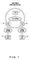
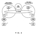
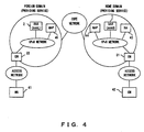
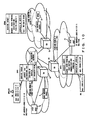
- FIGS. 1 through 4 show the configurations of the service control network according to an embodiment of the present invention.
- the service control network according to the present invention is based on the IPv6 network, and includes an AAA (Authentication, Authorization, and Accounting) server which authenticates a terminal device, a router device as a communication node configuring the IPv6 network, an access network connecting the IPv6 network to a terminal device, and the IPv6 host as a terminal device.
- AAA Authentication, Authorization, and Accounting
- the network shown in FIG. 1 is configured by a single domain.
- the domain is managed by a service provider.
- the IPv6 host belonging to the domain is authenticated by an AAA server 1.
- IPv6 hosts 11 and 12 are terminal devices having the communications functions according to the IPv6 protocol, and respectively belong to the domain.
- the user of the IPv6 hosts 11 and 12 has entered a subscriber contract with a service provider for managing the domain.
- the IPv6 hosts 11 and 12 are accommodated by edge nodes 21 and 22, respectively.
- An edge node can be realized by, for example, an IPv6 router device.
- the network shown in FIG. 2 is configured by a plurality of domains. Then, the AAA server 1 is provided in the home domain of the IPv6 hosts 11 and 12, and an AAA server 2 is provided in the foreign domain.
- the IPv6 host 11 moves from the communications area of a home domain to the communications area of a foreign domain, and is accommodated by the edge node 22.
- the IPv6 hosts 11 and 12 are authenticated by the AAA server 1. That is, the AAA server 1 works as an AAAH for the IPv6 hosts 11 and 12, and the AAA server 2 works as an AAAL or an AAAF for the IPv6 hosts 11 and 12.
- the network shown in FIG. 3 is configured by a plurality of domains as in the network shown in FIG. 2.
- the network shown in FIG. 2 has the configuration in which each domain provides a service such as a QoS, etc.
- the network shown in FIG. 3 has the configuration in which a domain for providing a service is connected to a domain incapable of providing a service.
- a service can be provided in the home domain while no service can be provided in the foreign domain.
- the home domain and the foreign domain are interconnected to each other through a gateway edge node 31, a core network, and a gateway edge node 32.
- the network shown in FIG. 4 supports a mobile IPv6. That is, a mobile node (MN) 41 is connected to the IPv6 network according to the mobile IPv6. In the mobile IPv6, the location of the mobile node 41 is recorded in a home agent (HA) 43. A correspondent of the mobile node 41 is hereinafter referred to as a correspondent node (CN) 42. It is assumed that a hierarchical mobile IPv6 is used in this network. Therefore, mobility anchor points 44 and 45 are provided in the home domain and the foreign domain, respectively.
- MN mobile node
- HA home agent
- CN correspondent node
- AAA server The configurations and the operations of the AAA server, the edge node (EN), the gateway edge node (GEN), the home agent (HA), and the mobility anchor point (MAP) are described later in detail.
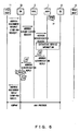
- FIG. 5 shows a basic sequence of delivering service control information. It is described based on the network shown in FIG. 2.
- the service control information about the IPv6 host 11 is delivered to the edge node 22.
- the IPv6 host 11 is authenticated by the AAA server (AAAH) 1.
- the service control information about the IPv6 host 11 is assumed to be stored in a database (SPDB) 51 accessible by the AAA server 1.
- SPDB database
- the IPv6 host 11 periodically receives an ICMP advertisement through a network, however not shown in FIG. 5.
- the ICMP advertisement is, for example, a message transmitted from a router device to each terminal.
- the ICMP advertisement is assumed to have been transmitted from the edge node 22 to the IPv6 host 11.
- the IPv6 host 11 Upon receipt of the ICMP advertisement, the IPv6 host 11 transmits an address assignment request (ICMP-AAA request) to the edge node 22 as necessary.
- the address assignment request is a message for request of a new IP address, and is defined by the ICMPv6.
- the IPv6 host 11 outputs an address assignment request when no IP address is held, when a previously assigned IP address expires, when it moves from the communications area of a router device to the communications area of another router device, etc.
- the edge node 22 Upon receipt of the address assignment request, the edge node 22 determines the IP address to be assigned to the IPv6 host 11, and transmits an address authentication request to the AAA server (AAAL) 2.
- the AAA server 2 transfers the address authentication request to the AAA server (AAAH) 1.
- the AAA server (AAAH) 1 Upon receipt of the address authentication request, the AAA server (AAAH) 1 authenticates the IPv6 host 11, and extracts a service profile (SP) as the service control information about the IPv6 host 11 from the database (SPDB) 51.
- the AAA server (AAAH) 1 transmits the service profile of the IPv6 host 11 together with an address authentication reply to the edge node 22 through the AAA server (AAAL) 2.
- the edge node 22 Upon receipt of the address authentication reply and the service profile of the IPv6 host 11, the edge node 22 first stores the service profile in the cache of the device. Then, it returns to the IPv6 host 11 the address assignment reply (ICMP-AAA reply) as a reply to the address assignment request.
- the address assignment reply (ICMP-AAA reply)
- a new IPv6 address is assigned to the IPv6 host 11.
- the IPv6 host 11 is authenticated by the AAA server (AAAH) 1, and the service profile of the IPv6 host 11 is delivered to the edge node 22 which accommodates the IPv6 host 11.
- AAA server AAA server
- FIG. 6 shows the method of managing a delivered service profile.
- the procedure of delivering a service profile to the edge node 22 is shown in FIG. 5.
- the delivered service profile is managed using a network access identifier of a corresponding terminal device as a key.
- the network access identifier is identification information uniquely assigned to each terminal, and is not changed after the terminal device is moved.
- the network access identifier of the IPv6 host 11 is transmitted to the edge node 22 by an address assignment request (ICMP-AAA request).
- the edge node 22 holds host address information (HA) describing the correspondence between the network access identifier of the terminal device to which a corresponding service profile is delivered and the IPv6 address assigned to the terminal device.
- the network access identifier is included in the service profile transmitted from the AAA server 1.
- the host address information (HA) describing the correspondence between the network access identifier of the IPv6 host 11 and the IPv6 address newly assigned to the IPv6 host 11 is generated.
- FIG. 7 shows the sequence of an edge node obtaining the host address information about a correspondent.
- the IPv6 host 11 is accommodated by the edge node 22
- the IPv6 host 12 is accommodated by the edge node 21.
- the edge node 22 holds the service profile and the host address information about the IPv6 host 11
- the edge node 21 holds the service profile and the host address information about the IPv6 host 12. It is assumed that a data packet has been transmitted from the IPv6 host 11 to the IPv6 host 12.
- the edge node 22 When the edge node 22 detects that the above mentioned communications have been started, it transmits an NAI-SPC request to the edge node 21 accommodating the IPv6 host 12. On the other hand, upon receipt of the request, the edge node 21 transmits the host address information (HA2) about the IPv6 host 12 to the edge node 22 using an NAI-SPC reply. Thus, the edge node 22 obtains the host address information about the IPv6 host 12. That is, the edge node 22 obtains the network access identifier of the destination host. The edge node 22 obtains in advance the network access identifier of the source host. Therefore, the edge node includes the network access identifiers of the source host and the destination host.
- HA2 host address information
- the edge node 22 accesses a service profile using these network access identifiers, it extracts the service information specified for the communications in which the source host is the IPv6 host 11 and the destination host is the IPv6 host 12, thereby providing a corresponding service.
- data is transmitted from the IPv6 host 11 to the IPv6 host 12.
- the IPv6 host 11 and the IPv6 host 12 are respectively accommodated by the edge node 22 and the edge node 21 as shown in FIG. 8.
- the edge node 22 holds the service profile of the IPv6 host 11 delivered from the AAA server (AAAH) 1. The procedure of delivering a service profile has been described above by referring to FIG. 5.
- the service profile of the IPv6 host 11 is managed using the network access identifier of the IPv6 host 11 as a key.
- the edge node 22 holds the host address information about the IPv6 host 11. In this example, the correspondence between the IPv6 address of the IPv6 host 11 and the network access identifier of the Ipv6 host 11, and the correspondence between the IPv6 address of the IPv6 host 12 which is a correspondent of the IPv6 host 11 and the network access identifier of the IPv6 host 12 are stored.
- the edge node 22 detects the source IP address (2001:0:1:2::2) and the destination IP address (2001:0:1:1::1). Then, a set of network access identifiers (aaa and bbb) corresponding to the set of the above mentioned addresses is detected by referring to the host address information. Furthermore, the service information corresponding to the set of the network access identifiers is extracted from the service profile cache. Then, the transfer of a packet from the IPv6 host 11 to the IPv6 host 12 is controlled according to the extracted service information.
- the IPv6 host 12 has moved from the communications area of the edge node 21 to the communications area of an edge node 23.
- a new IPv6 address (2001:0:1:3::1) is assigned to the IPv6 host 12, and the IPv6 host 12 is authenticated.
- the service profile of the IPv6 host 12 is delivered from the corresponding AAA server 1 to the edge node 23, and the host address information HA describing the correspondence between the network access identifier of the IPv6 host 12 and a new IPv6 address is generated.
- a data packet is transmitted from the IPv6 host 11 to the IPv6 host 12.
- the destination IP address of the packet is the IPv6 address (2001:0:1:3::1) newly assigned to the IPv6 host 12.
- an old IPv6 address (2001:0:1:1::1) assigned to the IPv6 host 12 is set in the host address information HA held by the edge node 22. Therefore, the edge node 22 cannot use the service profile corresponding to the packet received from the IPv6 host 11.
- the edge node 22 obtains the host address information about the IPv6 host 12 from the edge node 23 accommodating the IPv6 host 12 by performing the procedure shown in FIG. 7.
- the edge node 23 transmits the host address information about the IPv6 host 12 (or the host address information and the service profile of the IPv6 host 12) to the edge node 22 in response to the NAI-SPC request.
- the edge node 22 updates the host address information in the device as shown in FIG. 10.
- the edge node 22 can use the service profile corresponding to the packet from the IPv6 host 11 to the IPv6 host 12, and the packet can be controlled according to the service profile.
- the service profile of the IPv6 is managed by a corresponding network access identifier in each edge node, and the correspondence between the network access identifier of the IPv6 host and the IPv6 address is managed. Then, the information required to provide a corresponding service is transmitted and received between edge nodes when the communications between terminal devices are started. Accordingly, although the IP address of the IPv6 is changed, it is not necessary to deliver a service profile from an AAA server to an edge node again.
- the service profile of the IPv6 is managed by a corresponding IP address, then the service profile has to be delivered from the AAA server to a corresponding edge node each time the IP address of the IPv6 is changed. This configuration imposes heavy loads on the AAA server.
- IPv6 packet is configured by an IPv6 header and a payload.
- IPv6 header is configured by version information, a traffic class, a flow label, a payload length, a next header, a hop limit, a source address, and a destination address.
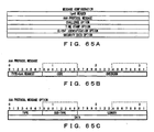
- FIG. 65A shows the configuration of an ICMP-AAA request message.
- the message is transmitted from the IPv6 host which receives an ICMP advertisement to a router device (edge node), and is configured by an AAA protocol message, a challenge option, a time-stamp option, a client identification option, and a security data option.
- the configuration of an AAA protocol message is shown in FIG. 65B.
- the AAA protocol message can also be provided with an AAA protocol message option shown in FIG. 65C.
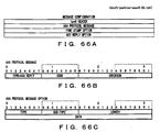
- FIG. 66A shows the configuration of an ICMP-AAA reply message.
- the message is returned from a router device (edge node) to the IPv6 host in response to an ICMP-AAA request message, and is configured by an AAA protocol message, a time stamp option, a key reply option.
- the configuration of the AAA protocol message is shown in FIG. 66B.
- the AAA protocol message can also be provided with an AAA protocol message option shown in FIG. 66C.
- FIG. 67 shows the configuration of a packet containing a DIAMETER message to be transmitted.
- the DIAMETER message is stored in an SCTP packet as shown in FIG. 67A, and the SCTP packet is stored in the payload of the IPv6 packet.
- the DIAMETER is one of the AAA protocols.
- the SCTP packet is configured by an SCTP common header and a plurality of chunks.
- the configuration of the SCTP common header is shown in FIG. 67C.
- the "DIAMETER" is specified as a destination port number.
- the DIAMETER message has a DIAMETER header shown in FIG. 67D.
- the type of message can be identified by the command code in the header.
- the AVP area following the header stores the data corresponding to the message.
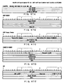
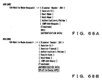
- FIG. 68A shows the data structure of an AHR (AMR) message.
- the AHR message is one of the existing DIAMETER messages, and is used by a router device (edge node) to request the AAA server to authenticate an IPv6 host.
- the network access identifier of an IPv6 host to be authenticated is set, and the message contains an ICMP-AAA request according to the embodiment of the present invention.
- FIG. 68B shows the data structure of an AHA (AMA) message.
- the AHR message is one of the existing DIAMETER messages, and is returned from the AAA server to the router device (edge node) when the AHR message is generated.
- the message includes an ICMP-AAA reply, and can store the service profile of the IPv6 authenticated by the AAA server according to the embodiment of the present invention. In this case, the service profile is stored in the "profile cache AVP".
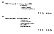
- FIG. 69A shows the data structure of an ASR message.
- the ASR message is newly introduced in the network according to the embodiment of the present invention, and is used by the mobility anchor point to request the AAA server for a service profile of a mobile node in the hierarchical mobile IPv6.
- a unique value different from the values of other messages is used for the command code of the message.
- FIG. 69B shows the data structure of an ASA message.
- the ASA message is newly introduced in the network according to the embodiment of the present invention, and is returned from the AAA server to the mobility anchor point in the hierarchical mobile IPv6.
- the message has an area for storing the service profile requested by the ASR message.
- a unique value different from the values of other messages is used for the command code of the message.
- FIG. 70A shows the data structure of an HHR message.
- the HHR message is one of the existing DIAMETER messages, and is used by the AAA server to notify the gateway edge node, the home agent of the IPv6, or the mobility anchor point of the hierarchical mobile IPv6 of the information about the location of the corresponding terminal device.
- the message can store a service profile of a corresponding terminal device or mobile node.
- FIG. 70B shows the data structure of an HHA message.
- the HHA message is one of the existing DIAMETER messages, and is returned to the AAA server from the gateway edge node, the home agent of the mobile IPv6, or the mobility anchor point of the hierarchical mobile IPv6 which received the HHR message.
- FIG. 70C shows the data structure of an STR message.
- the STR message is one of the existing DIAMETER messages to request to terminate a session.
- FIG. 70D shows the data structure of an STA message.
- the STA message is one of the existing DIAMETER messages, and is issued in response to the STR message.
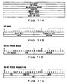
- FIG. 71 shows the data structure of the NAI-SPC request message.
- the NAI-SPC request message is newly introduced in the network according to the embodiment of the present invention, and is stored in an UDP packet as shown in FIG. 71A.
- the UDP packet is stored in the payload of the IPv6 packet.
- the NAI-SPC request message is used to request to solve the NAI between the router devices (edge nodes).
- an IPv6 address corresponding to a target network access identifier is set in this message.
- this message can also be used to transmit a service profile and/or host address information between the router devices (edge nodes).
- FIG. 71B shows the configuration of a UDP header.
- FIGS. 71C and 71D show data structures of an NAI-SPC protocol message and an NAI-SPC protocol message option included in the NAI-SPC request, respectively.
- FIG. 72 shows the data structure of an NAI-SPC reply message.
- the NAI-SPC reply message is newly introduced in the network according to the embodiment of the present invention, and is stored in the UDP packet as shown in FIG. 72A.
- the NAI-SPC reply message is issued in response to the NAI-SPC request message, and can store a service profile and/or host address information. The message can also be used to return the result of the solution to the requested NAI.
- FIGS. 72B and 72C show the data structures of the NAI-SPC protocol message and the NAI-SPC protocol message option included in the NAI-SPC reply, respectively.
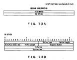
- FIG. 73 shows the data structure of a binding update message.
- the binding update message is one of the existing mobile Ipv6 messages, and is used to perform a binding update process when a mobile node is moved.
- the message is stored in the payload of the IPv6 packet as shown in FIG. 73A.
- FIG. 73B shows the data structure of the binding update message.
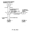
- FIG. 74 shows the data structure of an ICMP-AAA-Teardown request message.
- This request message requests to disable the provided service, and is configured by an AAA protocol message, a challenge option, a time stamp option, a client identification option, and a security data option, as shown in FIG. 74.
- FIG. 74B shows the data structure of the AAA protocol message of the ICMP-AAA-Teardown request message.
- FIG. 74C shows the data structure of an AAA protocol message option of the ICMP-AAA-Teardown request message.
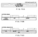
- FIG. 75 shows the data structure of an ICMP-AAA-Teardown reply message. This reply message is issued in response to the ICMP-AAA-Teardown request message, and is configured by an AAA protocol message and a time stamp option, as shown in FIG. 75A.
- FIG. 75B shows the data structure of an AAA protocol message of the ICMP-AAA-Teardown reply message.
- FIG. 75C shows the data structure of an AAA protocol message option of the ICMP-AAA-Teardown reply message.
- the IPv6 host is a subscriber terminal communicating data through the IPv6.
- the mobile node MN is a subscriber terminal communicating data through the mobile IPv6.
- These subscriber terminals have the functions of connecting to a cable LAN such as Ethernet, etc., a radio LAN, a radio access network such as a CDMA, etc.
- a correspondent node CN is an IPv6 host communicating with a mobile node. Configuration and Operation of AAA server
- An AAA server is one or more server computers for authentication, authorization, and accounting an IPv6 host or a mobile node, and is named in an IETF.
- a protocol for the AAA server can be DIAMETER ⁇ draft-calhoun-diameter-12.txt>, ⁇ draft-calhoun-diameter-mobileip-07.txt>.
- An AAA server which performs authentication/authorization/accounting for a subscriber is an "AAAH (AAA Home)" for the subscriber.
- An AAA server other than the AAAH is an "AAAF (AAA foreign)" or "AAAL (AAA local)" for the subscriber.
- the AAA server used in the service control network has also the functions of, in addition to the above mentioned basic functions, extracting from the database (SPDB) 51 a service profile as service control information corresponding to the NAI (network access identifier) of the subscriber terminal when an IPv6 address is assigned to the subscriber terminal, and delivering the service profile to the router device, etc. accommodating the subscriber terminal.
- SPDB database
- NAI network access identifier
- FIG. 11 is a function block diagram of the AAA server.
- a network interface 101 terminates a line connected to the IPv6 network.
- a protocol control unit 102 analyzes a packet received through the network interface 101, and performs a corresponding process depending on the type of the packet. If the received packet contains a message relating to the embodiment of the present invention, the protocol control unit 102 requests a service data management unit 103 to perform the process corresponding to the message. For example, a request to extract a corresponding service profile from a service profile database 104, a request to access a service specification data 105, etc. are generated.
- the service data management unit 103 accesses the service profile database 104 or the service specification data 105 at a request from the protocol control unit 102.
- the service profile database 104 stores the service control information (service profile) about each subscriber belonging to the domain managed by the AAA server.
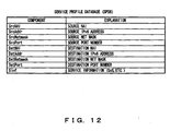
- FIG. 12 shows an example of a service profile stored in the service profile database 104.
- a service profile is fundamentally recorded for each service in the service profile database 104, and each service profile is managed using as a key the NAI of the subscriber who obtains the service.
- a QoS class, etc. is set as service information.
- the service profile can describe not only the one-to-one inter-IPv6-host communications but also the one-to-many inter-IPv6-host communications, the many-to-one inter-IPv6-host communications, and the many-to-many inter-IPv6-host communications. If a plurality of IPv6 hosts are set in the service profile, a wild card can be used to specify an IPv6 address, or a net mask can be appropriately set. For example, in the network shown in FIGS.
- the "source IPv6 address” and the “destination IPv6 address” are respectively set to "2001:0:1:2::2" and "2001:01:3:*".
- the service specification data 105 stores the service profile delivered from the AAAH and the host address information when the AAA server operates as an AAAL.
- the service profile is stored in the original service profile cache (OSPC), and the host address information is stored in the original host address cache (OHAC).
- FIG. 13A shows an embodiment of the original service profile cache (OSPC).
- the original service profile cache (OSPC) stores a service profile for each IPv6 host and service.
- Each service profile is recorded using the NAI (NAI-ID) of the IPv6 host to be managed as a key.
- NAI-ID NAI-ID
- the recorded information can be a "source NAI”, a "source IPv6 address”, a “source net mask”, a "source port number”, a “destination NAI”, a “destination IPv6 address”, a “destination net mask”, a "destination port number”, a “service information”, etc.
- NAI-ID NAI-ID
- the original service profile cache (OSPC) storing the service profile of the IPv6 host 11 is as follows.
- the service relating to the transmission of data from the IPv6 host 11 to the IPv6 host 12 is specified.
- Target host NAI identifier aaa
- FIG. 13B shows an example of an original host address cache (OHAC).
- a "target host IPv6 address”, an “Lifetime”, an "AAA relevant information”, a “destination IPv6 address”, etc. are recorded in the original host address cache (OHAC) using the NAI (NAI-ID) of the IPv6 host to be managed as a key.
- the "target host IPv6 address” is assigned to the IPv6 host to be managed. Therefore, when the IPv6 address assigned to the IPv6 host is changed, the “target host IPv6 address” is updated correspondingly. As a result, the correspondence between the NAI of the IPv6 host and the current IPv6 address is constantly recorded.
- the “Lifetime” refers to the remaining time effectively available for the service profile corresponding to the IPv6 address.
- the "destination IPv6 address” refers to the IPv6 address of the destination entity when a service profile is delivered from the corresponding entity to another entity.
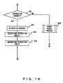
- FIGS. 14 through 16 are flowcharts of the operations of the protocol control unit 102 of the AAA server. The process is performed when a message is received from the network interface 101.
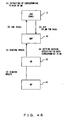
- step S1 it is checked whether or not an address authentication request has been received.
- the AHR message of the DIAMETER protocol is used as an address authentication request.
- the type of DIAMETER message is detected by, for example, the command code of the DIAMETER header shown in FIG. 67D.
- step S2 When an address authentication request is received, it is checked in step S2 whether or not the destination of the message is this AAA server. If the destination of the message is this AAA server, the processes in and after step S3 are performed. Otherwise, control is passed to step S9.
- steps S3 through S8 are performed by the AAAH.
- the authenticating process is performed, and the service data management unit 103 is requested to extract a service profile corresponding to the NAI of the IPv6 host set in the address authentication request.
- a corresponding service profile is received from the service data management unit 103.
- step S5 it is checked whether or not there is a home agent for recording the location (address) of the IPv6 host associated with the address authentication request.
- the home agent is provided in the mobile IPv6 network.
- step S6 it is checked whether or not there is a gateway edge node.
- a gateway edge node is provided in, for example, the network shown in FIG. 3.
- an address authentication reply is generated in step S7.
- the address authentication reply includes a service profile obtained in step S4, and the AHA message of the DIAMETER protocol is used to transmit it.
- a setting request is generated in step S8.
- the setting request includes the service profile obtained in step S4, and the HHR message of the DIAMETER protocol is used to transmit it
- step S9 a packet storing a generated message is passed to the network interface 101, thereby transmitting the generated message to the network.
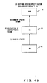
- step S11 it is checked whether or not a delete request has been received.
- the delete request is an STR message in the DIAMETER protocol. If the delete request has been received, then a delete request is transmitted to the service data management unit 103.
- the delete request includes a request to delete the session information not shown in the attached drawings. If a delete reply is received from the service data management unit 103 in step S13, then a delete reply message is generated in step S14.
- the delete reply message is stored in a packet in step S9, and is returned to the source of the delete request.
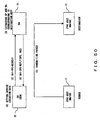
- step S21 it is checked whether or not an address authentication reply has been received.
- the address authentication reply is an AHA message in the DIAMETER protocol. If the address authentication reply has been received, then the processes in steps S22 through S25 are performed. The processes in steps S22 through S25 are performed by the AAAL.
- step S22 a setting request is transmitted to the service data management unit 103.
- the setting request is an instruction to store a service profile received together with the address authentication request in the service specification data 105. If the setting reply corresponding to the setting request is received in step S23, then it is checked in step S24 whether or not there is a mobility anchor point.
- the mobility anchor point is described later in detail, but exists in a hierarchical mobile IPv6 network.
- step S25 a setting request is generated in step S25.
- the setting request is the same as the setting request generated in step S8, but the destination is the mobility anchor point. If there is no mobility anchor point, then step S25 is omitted. In this case, the received address authentication reply is transmitted as is.
- step S31 it is checked whether or not a setting reply has been received.
- the setting reply is a message corresponding to the setting request, and is an HHA message in the DIAMETER protocol. If the setting reply has been received, then it is checked in step S32 whether or not the source of the setting reply is a gateway edge node.
- step S33 If the setting reply has been received from the gateway edge node, an address authentication reply is generated in step S33. In this case, the address authentication reply does not include a service profile. On the other hand, if a setting reply has been received from an entity other than the gateway edge nodes, in steps S34 and S35, a corresponding service profile is obtained. In this case, address authentication reply generated in step 33 includes the service profile.
- step S41 it is checked whether or not an extraction request has been received.
- the extraction request is a message for requesting a service profile to be delivered, and can be realized by the ASR message shown in FIG. 69A according to the embodiment of the present invention. If an extraction request has been received, the extraction request is transmitted to the service data management unit 103 in step S42, and a corresponding service profile is obtained in step S43. Then, an extraction reply is generated in step S44. The extraction reply is realized by the ASA message shown in FIG. 69B. The extraction reply includes the service profile obtained in step S43.
- step S45 If the received packet does not store an address authentication request, a deletion request, an address authentication reply, a setting reply, or an extraction request, then other processes are performed in step S45.
- the protocol control unit 102 generates a corresponding message based on the received message, and transmits a request to extract/set/delete a corresponding service profile to the service data management unit 103 as necessary.
- the service profile is obtained, it is transmitted together with the generated message to a corresponding entity.
- FIG. 17 is a flowchart of the operation of the service data management unit 103 of the AAA server. This process is performed when a request is received from the protocol control unit 102.
- steps S51 through S53 it is checked whether or not an extraction request, a setting request, or a deletion request has been received.
- a deletion reply is transmitted to the protocol control unit 102 in step S55 after deleting the corresponding information from the service specification data 105 in step S54.
- the processes in steps S54 and S55 are performed in the AAAL.
- a service profile and/or host address information is set in the service specification data 105 in step S56. Then, a setting reply is transmitted to the protocol control unit 102 in step S57.
- the processes in steps S56 and S57 are performed in the AAAL.
- a corresponding service profile is extracted from the service profile database 104 or the service specification data 105 in step S58.
- the AAAH extracts a service profile from the service profile database 104, and the AAAL extracts it from the service specification data 105.
- the service profile is transmitted together with an extraction reply to the protocol control unit 102 in step S59.
- a home agent is an entity having a home address of a mobile node in the mobile IPv6 network, and is provided with a table containing the record of the location of a mobile node.
- the packet When a packet addressed to the home address of a mobile node, the packet is capsuled and transferred to the care-of-address of the mobile node.
- a "care-of-address of a mobile node” refers to an IP address assigned to the mobile node in the destination domain.
- the home agent has the functions of caching the service profile of a mobile node delivered from the AAA server, generating and caching the host address information relating to the service profile, and extracting and transferring the cached service profile and host address information.
- the mobility anchor point is an entity which works as a lower order home agent in a foreign domain in the hierarchical mobile IPv6 in which the functions of a home agent are hierarchically managed.
- the functions of a mobility anchor point are described below by referring to FIG. 18.
- the location of a mobile node is identified by an RCOA (regional care-of-address) and an LCOA (local care-of-address).
- the RCOA is an address for identifying the mobility anchor point (MAP) for managing the communications area in which the mobile node is located.
- the LCOA is an address used in an area managed by each mobility anchor point.
- a mobile node roams from an area managed by a mobility anchor point (MAP-A) to an area managed by another mobility anchor point (MAP-B)
- the notification of the RCOA is issued to the home agent
- the notification of the LCOA is issued to the mobility anchor point (MAP-B).
- the mobile node moves within an area managed by one mobility anchor point, then the location is recorded in the mobility anchor point, but the location is not recorded in the home agent.
- the mobility anchor point is described in detail in ⁇ draft-ietf-mobileip-hmipv6-02.txt> issued by the IETF.
- the mobility anchor point has the functions of caching the service profile of a mobile node delivered from the AAA server or an edge node, generating and caching the host address information relating to the service profile, and extracting and transferring the cached service profile and host address information.
- FIG. 19 is a block diagram of the functions of a home agent and a mobility anchor point.
- a network interface 201 terminates the line connected to the IPv6 network.
- a protocol control unit 202 analyzes a packet received through the network interface 201, and performs a corresponding process depending on the type of the packet. If the received packet contains a message according to the embodiment of the present invention, the protocol control unit 202 requests a service data management unit 203 to perform the process corresponding to the message. For example, a request to access a service specification data 204, etc. is generated.
- the service data management unit 203 accesses the service specification data 204 at a request from the protocol control unit 102.
- the service specification data 204 is basically the same as the service specification data 105 in AAA server.
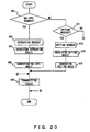
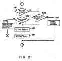
- FIGS. 20 and 21 are flowcharts of the operations of the protocol control unit 202 of the home agent or a mobility anchor point. This process is performed when a message is received from the network interface 201.
- step S61 it is checked whether or not an NAI-SPC request has been received.
- the data structure of the NAI-SPC request is shown in FIG. 71.
- a request to extract a corresponding service profile is issued to the service data management unit 203 in step S62.
- an NAI-SPC reply is generated in step S64.
- the NAI-SPC reply includes the service profile received in step S63.
- step S65 a packet storing a generated message is passed to the network interface 201, thereby transmitting the generated message to the network.
- step S71 it is checked whether or not a setting request has been received.
- a setting request includes a corresponding service profile, and is realized by an HHR message of the DIAMETER protocol according to the embodiment of the present invention
- the service data management unit 203 When a setting request is received, the service data management unit 203 is requested in step S72 to set in the service specification data 204 the service profile contained in the setting request. If a setting reply corresponding to the above mentioned setting request is received in step S73, a setting reply message is generated in step S74.
- the setting reply message is an HHA message in the DIAMETER protocol.
- step S81 it is checked whether or not binding update message has been received. If binding update message has been received, it is checked in step S82 whether or not the binding update message includes the service profile of the IPv6 host.
- the processes in steps S83 and S84 are performed. That is, the service data management unit 203 is requested to set in the service specification data 204 the service profile contained in the message, and a corresponding setting reply is received.
- the binding update message does not include the service profile of the IPv6 host, an extraction request is generated in step S85. This extraction request is realized by the ASR message shown in FIG. 69A.
- step S86 It is checked in step S86 whether or not an extraction reply has been received.
- the extraction reply is realized by the ASA message shown in FIG. 69B.
- the extraction reply stores a service profile extracted according to the extraction request generated in step S85.
- the processes in steps S83 and S84 are performed.
- step S87 If a received packet does not store an NAI-SPC request, a setting request, binding update message, or an extraction reply, other processes are performed in step S87.
- the protocol control unit 202 generates a corresponding message according to a received message, and transmits a request relating to extracting/setting a corresponding service profile to the service data management unit 203 as necessary. When it obtains the service profile, it transmits the service profile together with the generated message to the corresponding entity.
- the operation of the service data management unit 203 of a home agent or a mobility anchor point is basically the same as the operation of the service data management unit 103 of the AAA server shown in FIG. 17. Therefore, the explanation is omitted here.
- An edge node is an IPv6 router device located at the edge of a domain.
- the edge node according to the embodiment has the following four functions in addition to a general routing functions.
- a gateway edge node is an IPv6 router device located at the gateway of each provider network.
- the gateway edge node according to the embodiment has the above mentioned functions (1) through (4) of the edge node in addition to the general gateway functions.
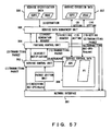
- FIG. 22 is a function block diagram of an edge node and a gateway edge node.
- a network interface 301 terminates the line connected to the IPv6 network.
- a service control unit 302 Upon receipt of a packet through the network interface 301, a service control unit 302 checks whether or not the IPv6 address of the source host and the IPv6 address of the destination host of the packet are cached in the address cache (ADC) in a service control data 308. If both of the IPv6 addresses of the hosts have been cached, it is determined that the service information for the communications between the hosts can be effective, and the service control unit 302 requests a packet edition unit 303 to perform the service. On the other hand, if the IPv6 address of at least one of the source host and the destination host has not been cached, the packet received through the network interface 301 is transmitted to a protocol control unit 304, and a hit miss notification is transmitted to a service data management unit 305.
- ADC address cache
- the address cache (ADC) is periodically monitored, and the service data management unit 305 is notified of the expiration of the lifetime when the expiration of the lifetime set for each IPv6 address is detected.
- the address checking process and the lifetime counting process depend on the configuration of the address cache (ADC).
- the packet edition unit 303 Upon receipt of a packet through the service control unit 302, the packet edition unit 303 extracts the service information (service profile) corresponding to the source host and the destination host of the packet from the policy table (PT) in the service control data 308, and provides the service according to the service information. Then, as necessary, the packet is transmitted to the network through the network interface 301.
- service information service profile
- PT policy table
- the protocol control unit 304 analyzes a packet received through the service control unit 302, and performs the process corresponding to the type of the packet. Practically, if the received packet includes a message relating to the present embodiment, then the protocol control unit 304 requests the service data management unit 305 to access (extract, set, and delete various information) service specification data 306, and access (set and delete various information) service execution data 307 and the service control data 308.
- the service data management unit 305 accesses (extract, set, and delete various information) the service specification data 306, and accesses (set and delete various information) the service execution data 307 and the service control data 308.
- the service data management unit 305 requests the protocol control unit 304 to generate an NAI-SPC request message so as to obtain the host address information and/or service information about the destination host.
- the service data management unit 305 nullifies or deletes the corresponding information in the service execution data 307 and the service control data 308.
- the setting process and the deleting process of the service execution data 307 and the service control data 308 depend on the configuration of the address cache (ADC).
- the service specification data 306 comprises an original service profile cache (OSPC) for storing the service information delivered from the AAA server when an address is assigned to the IPv6 host accommodated by the node, and an original host address cache (OHAC) for storing the host address information about the IPv6 host.
- OSPC original service profile cache
- OHAC original host address cache
- the configuration of the service specification data 306 is basically the same as the service specification data 105 in the AAA server.
- the service execution data 307 comprises a communicating service profile cache (CSPC) for storing the service information (service profile) about the hosts, and a communicating host address cache (CHAC) for storing the host address information about the hosts.
- CSPC communicating service profile cache
- CHAC communicating host address cache
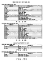
- FIGS. 23A and 23B show examples of a source service profile cache (SSPC) and a destination service profile cache (DSPC) in the communicating service profile cache (CSPC) respectively.
- a “service profile identifier” refers to an identifies a service profile generated for each IPv6 host and service. For the "source NAI” through “service information”, the information stored in the service specification data 306 is basically stored as is.
- the “service execution state” indicates whether or not the “source NAI” through “service information” set in the communicating service profile cache (CSPC) are available.
- FIGS. 23C and 23D show examples of a source host address cache (SHAC) and a destination host address cache (DHAC) in the communicating host address cache (CHAC), respectively. These caches store the correspondence between the NAI of the source IPv6 host and the source IPv6 address, and the correspondence between the NAI of the destination IPv6 host and the destination IPv6 address.
- HAC source host address cache
- DHAC destination host address cache
- CHAC communicating host address cache
- FIG. 24 shows the method of generating the service execution data 307.
- a packet is transferred from the IPv6 host-A accommodated by the edge node-A to the IPv6 host-B accommodated by the edge node-B.
- the service execution data 307 of the edge node-A is set is described below.
- the service profile of the IPv6 host-A which is a source host, is set in the source service profile cache (SSPC).
- the service profile of the IPv6 host-A is stored in the service specification data 306 of the edge node-A accommodating the IPv6 host-A. Therefore, the service profile to be set in the source service profile cache (SSPC) is obtained from the service specification data 306 of the edge node-A.
- the service profile of the IPv6 host-B which is a destination host, is set in the destination service profile cache (DSPC).
- the service profile of the IPv6 host-B is stored in the service specification data 306 of the edge node-B accommodating the IPv6 host-B. Therefore, the service profile to be set in the destination service profile cache (DSPC) is obtained from the service specification data 306 of the edge node-B.
- the host address information to be set in the source host address cache is obtained from the service specification data 306 of the edge node-A
- the host address information to be set in the destination host address cache (DHAC) is obtained from the service specification data 306 of the edge node-B.
- the service execution data of the edge node accommodating the source host is set, but the service execution data can also be set in the edge node accommodating the destination host.
- the service control data 308 comprises the policy table (PT) for caching the service information (service profile) enabled in the service execution data 307, and the address cache (ADC) for caching the IPv6 address of the IPv6 host corresponding to the service information enabled in the service execution data 307.
- the address cache (ADC) can be configured such that a source address and a destination address are individually managed, and can also be configured such that the combination of a source address and a destination address is managed corresponding to each service.
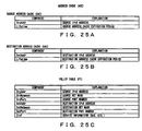
- FIGS. 25A through 25C show examples of a source address cache (SAC), a destination address cache (DAC), and a policy table (PT) in a case where the IPv6 addresses of the source host and the destination host are individually managed. In this case, the lifetime of each of the source IPv6 addresses and the destination IPv6 addresses is managed.
- SAC source address cache
- DAC destination address cache
- PT policy table
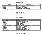
- FIGS. 26A and 26B show examples of the address cache (ADC) and the policy table (PT) in a case where a combination of the IPv6 addresses of a source host and a destination host is managed for each service.
- the policy table (PT) is managed using a service profile identifier as a key for identification of a combination of a source IPv6 host and a destination IPv6 host.
- the configuration for individual managing a source address and a destination address has a reduced size of memory for generating the address cache (ADC).
- the configuration for managing a combination of a source address and a destination address for each service shortens a retrieval time for the address cache (ADC).
- a service profile of a source host and a service profile of a destination host in the communications can be set in the service execution data 307.
- a service profile specified for the IPv6 host for the service relating to the transfer of a packet from the IPv6 host-A to the IPv6 host-B, and a service profile specified for the IPv6 host-B for the same service are stored in the service execution data 307 of the edge node-A. That is, two sets of service profiles are set for one service in the service execution data 307.
- the edge node enables a service profile of the highest priority, and other service profiles are nullified.
- the service profile enabled by the service execution data 307 is recorded in the policy table (PT) of the service control data 308.
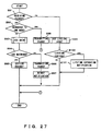
- FIG. 27 is a flowchart of the operations of the service control unit 302 of an edge node or a gateway edge node. This process is performed at predetermined intervals.
- step S91 it is checked whether or not a packet has been received through the network interface 301.
- step S92 it is checked whether or not the destination of a received packet is the IPv6 host accommodated by this edge node. If the destination of the received packet is the IPv6 host accommodated by this edge node, then the packet is transmitted to the protocol control unit 304 in step S98.
- the destination of the received packet is not the IPv6 host accommodated by this edge node, then it is checked in steps S93 and S94 whether or not the source address and the destination address of the packet are stored in the address cache (ADC) of the service control data 308. If there is a hit in the address cache (ADC), then the packet is edited according to the policy table (PT) of the service control data 308 in step S95. The "edit” includes the process of rewriting the header of a packet. On the other hand, if there is no hit in the address cache (ADC), then the packet is passed to the protocol control unit 304 in step S96. Furthermore, in step S97, a hit miss notification is transmitted to the service data management unit 305.
- ADC address cache
- step S91 If no packet is received ("NO" in step S91), the lifetime (expiration period) managed in the address cache (ADC) of the service control data 308 is checked. If the lifetime of the source address or the destination address is over, a lifetime expiration notification is transmitted to the service data management unit 305. On the other hand, if the lifetime remains, then step S101 is omitted. The lifetime of each IPv6 address managed in the address cache (ADC) of the service control data 308 is periodically decremented.
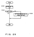
- FIGS. 28 and 29 are flowcharts of the process of checking the address cache, and corresponds to step S93 shown in FIG. 27.
- FIG. 28 is a flowchart of individually managing the source address and the destination address, and the address cache shown in FIGS. 25A and 25B is checked.
- FIG. 29 is a flowchart of managing a combination of a source address and a destination address corresponding to each service, and the address cache shown in FIG. 26A is checked.
- step S111 and S112 it is checked in steps S111 and S112 whether or not the source address set in the header of the received packet is stored in the source address cache (SAC) in the address cache (ADC) of the service control data 308. If there is no hit in the source address cache (SAC), a hit miss notification message is generated and the cause of the hit miss for the message is written in step S113. If there is a hit in the source address cache (SAC), step S113 is omitted.
- step S114 it is checked in steps S114 and S115 whether or not the destination address set in the header of the received packet is stored in the destination address cache (DAC). If there is no hit in the destination address cache (DAC), then the cause of the hit miss for the hit miss notification message is written in step S116.
- DAC destination address cache
- step S121 and S122 it is checked in steps S121 and S122 whether or not the combination of the source address and the destination address set in the header of the received packet is stored in the address cache (ADC) of the service control data 308. If there is no hit in the address cache (ADC), a hit miss notification message is generated in step S123, and the cause for the hit miss corresponding to the message is written. If there is a hit in the address cache (ADC), then step S123 is omitted.
- the hit miss notification message is generated.
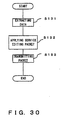
- FIG. 30 is a flowchart of the operation of the packet edition unit 303 of an edge node or a gateway edge node. This process is performed when an edition request is received from the service control unit 302.
- the service control unit 302 outputs an edition request when a source address and a destination address of a received packet are stored in the address cache of the service control data 308.
- step S131 information (service profile, etc.) about a received packet is extracted from the policy table (PT) of the service control data 308.
- step S132 a packet is edited according to the information extracted from the policy table.
- step S133 the edited packet is transmitted through the network interface 301.
- FIGS. 31 through 34 are flowcharts of the operations of the protocol control unit 304 of an edge node or a gateway edge node. This process is performed when a packet is received from the service control unit 302 or a packet generation request is received from the service data management unit 305.
- step S141 it is checked whether or not a packet is received from the service control unit 302.
- step S142 it is checked whether or not an NAI-SPC request message is included in the received packet. If the received packet includes an NAI-SPC request message, then it is checked in step S143 whether or not the message includes an extraction request.
- an extraction request is included in the NAI-SPC request message, then the extraction request is transmitted to the service data management unit 305 in step S144.
- the extraction request requests a corresponding service profile and/or host address information to be extracted from the service specification data 306.
- a corresponding service profile and/or host address information is received from the service specification data 306.
- an NAI-SPC reply message is generated. This message stores the service profile and/or host address information obtained in step S145.
- a packet storing the generated message is transmitted.
- a setting request or a deletion request is transmitted to the service data management unit 305 in step S147.
- the setting request is a request to set the service profile and/or host address information transmitted together with the NAI-SPC request message in the service execution data 307.
- the deletion request is a request to delete the service profile and/or host address information specified in the NAI-SPC request message from the service execution data 307.
- step S151 it is checked whether or not an ICMP-AAA request message is included in a received packet. If the ICMP-AAA request message is included in the received packet, then the IPv6 address to be assigned to the IPv6 host which has transmitted the ICMP-AAA request is determined in step S152, and an AHR message including an authentication request is generated.
- step S154 it is checked whether or not an address authentication reply message is included in the received packet. If the address authentication reply message is included in the received packet, then a request to set the service profile transmitted together with the address authentication reply message in the service specification data 306 is transmitted to the service data management unit 305 in step S155.
- step S156 the host address information about the IPv6 host which has transmitted the ICMP-AAA request is generated. The host address information is set in the original host address cache (OHAC) of the service specification data 306.
- step S157 the ICMP-AAA reply message to be transmitted to the IPv6 host which has transmitted the above mentioned ICMP-AAA request is generated.
- step S161 it is checked whether of not a binding update message is included in the received packet. If the binding update message is included in the received packet, then it is checked in step S162 whether or not the service profile of the corresponding IPv6 host is to be set in a mobility anchor point (MAP).
- MAP mobility anchor point
- a service profile is obtained in steps S163 and S164.
- the processes in steps S163 and S164 are the same as those in steps S144 and S145.
- step S165 a binding update message including the obtained service profile is generated.
- step S171 it is checked whether or not a deletion reply message is included in the received packet.
- the deletion reply message is realized by an STA message.
- step S172 the service data management unit 305 is requested to delete service profile and/or host address information corresponding to the deletion reply message.
- step S174 Upon receipt of a deletion reply from the service data management unit 305 in step S173, it is checked in step S174 whether or not the service profile and/or host address information to be deleted exists in other edge nodes. If the service profile and/or host address information deleted in steps S172 and S173 has been transmitted to other edge nodes, then they are to be deleted. If the service profile and/or host address information has been transmitted from this edge node to other edge nodes, then the destination address is recorded as the "destination IPv6 address" of the service specification data 306 (FIG. 13B).
- an NAI-SPC request message is generated in step S175. If there are no such information, then an AAA-Teardown reply message is generated in step S176.
- step S181 it is checked whether or not an NAI-SPC reply message is included in a received packet.
- step S182 it is checked whether or not a deletion reply is included in the received NAI-SPC reply message. If the deletion reply is included, then an AAA-Teardown reply message is generated in step S183. If no deletion reply is included, then a setting request is transmitted to the service data management unit 305 in steps S184 and S185. This setting request is issued to request a service profile and/or host address information transmitted together with the NAI-SPC reply message to be set in the service execution data 307.
- step S191 it is checked whether or not a setting request message is included in the received packet.
- step S192 a setting request is transmitted to the service data management unit 305.
- a setting reply message is generated in step S194.
- step S201 it is checked whether or not an AAA-Teardown request message is included in the received packet. If the AAA-Teardown request message is included, then a deletion request message is generated in step S202. The deletion request message is realized by an STR message.
- the received packet does not include an NAI-SPC request, an ICMP-AAA request, an address authentication reply, binding update information, a deletion reply, an NAI-SPC reply, a setting request, or an AAA-Teardown request, then other packet processes are performed in step S203.
- step S211 it is checked whether or not a packet generation request has been received from the service data management unit 305. If a packet generation request has been received, then a corresponding packet (including an NAI-SPC request, in this example) is generated in step S212.
- FIG. 35 is a flowchart of the operations of the service data management unit 305 of an edge node or a gateway edge node. This process is performed when a request is received from the protocol control unit 304 or a notification received from he service control unit 302.
- steps S221 through S225 the type of the request from the protocol control unit 304 or the type of the notification received from the service control unit 302 is detected.
- a specified service profile and/or host address information is extracted from the service specification data 306 in step S226. Then, in step S227, the extracted information is transmitted to the protocol control unit 304.
- a service profile and/or host address information transmitted together with the request is set in the service specification data 306 or the service execution data 307 in step S228.
- a setting reply is returned to the protocol control unit 304 as necessary.
- a deletion request is received, then a specified service profile and/or host address information is deleted from the service specification data 306 or the service execution data 307 in step S229. Then, a deletion reply is returned to the protocol control unit 304.
- step S230 If a hit miss notification is received, a corresponding hit miss process is performed in step S230. If a lifetime expiration notification is received, a corresponding lifetime expiration process is performed in step S231.
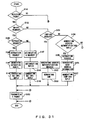
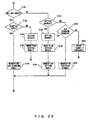
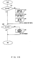
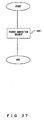
- FIGS. 36 and 37 are flowcharts of the processes performed when a hit miss is detected in the address cache, and correspond to step S230 shown in FIG. 35.
- FIG. 36 is a flowchart of the process performed when source addresses and destination addresses are individually managed.
- FIG. 37 is a flowchart of the process performed when the combination of a source address and a destination address corresponding to each service is managed.
- step S241 it is checked in step S241 whether or not a cache hit miss (source hit miss) has been found for a source IPv6 address.
- the type of cache hit miss is set in the hit miss notification generated by the service control unit 302.
- the information corresponding to the source address of the received packet is extracted from the service specification data 306 in step S242.
- a corresponding service profile is extracted from the original service profile cache (OSPC), and corresponding host address information is extracted from the original host address cache (OHAC).
- step S243 the information extracted in step S242 is set in the service execution data 307.
- the service profile is set in the source service profile cache (SSPC), and the host address information is set in the source host address cache (SHAC).
- the service profile enabled in step S243 is set in the policy table (PT) of the service control data 308, and the corresponding IPv6 address is set in the source address cache (SAC) in the address cache of the service control data 308.
- PT policy table
- SAC source address cache
- step S245 it is checked whether or not a cache hit miss (destination hit miss) has been detected for the destination IPv6 address. If a destination hit miss has been detected, a packet generation request is generated to generate a packet including an NAI-SPC request message. The packet generation request is transmitted to the protocol control unit 304. The NAI-SPC request message is issued to obtain a service profile and/or host address information corresponding to the destination address set in the received packet from the edge node accommodating the destination host.
- the above mentioned packet generation request is transmitted to the protocol control unit 304 when a hit miss is detected as shown in FIG. 37.
- steps S242 through S244 shown in FIG. 36 can be performed not only on the service profile of the destination address set in the packet in which the hit miss has been detected, but also on other service profiles.
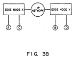
- a network shown in FIG. 38 is assumed.
- the IPv6 host-A and the IPv6 host-C are accommodated in the edge node-X
- the IPv6 host-B and the IPv6 host-D are accommodated in the edge node-Y.
- data is being transmitted from the IPv6 host-C to the IPv6 host-D.
- "IPv6 host-C" is set in the source address cache while "IPv6 host-D" is set in the destination address cache.
- IPv6 host-A and “IPv6 host-C” are set in the source address cache of the edge node-X, and "IPv6 host-B” and “IPv6 host-D” are set in the destination address cache.
- the service profile relating to the data transmission from the IPv6 host-A to the IPv6 host-B is enabled in the edge node-X.
- the service profile relating to the data transmission from the IPv6 host-A to the IPv6 host-B is enabled in the edge node-X.
- not only "IPv6 host-B” but also "IPv6 host-D" is set in the destination address cache. Therefore, if data transmission is started from the IPv6 host-A to the IPv6 host-D, there is no hit miss in the edge node-X. That is, in this case, it is necessary for the service profile relating to the data transmission from the IPv6 host-A to the IPv6 host-D to be set in the policy table (PT) of the service control data 308. Therefore, in the edge node-X, when the above mentioned source hit miss occurs a service profile relating to the communications from the IPv6 host-A to each destination address set in the destination address cache is to be enabled.
- PT policy table
- one of the service profiles is enabled when two or more service profiles are set for one service in service execution data 307.
- a service profile specified for the IPv6 host-A and a service profile specified for the IPv6 host-B are stored in the service execution data 307 of the edge node-A for the service relating to the packet transfer from the IPv6 host-A to the IPv6 host-B.
- the service profile for the former is extracted from the service specification data 306 of the edge node-A, and the service profile of the latter is obtained from the edge node-B.
- one of these two service profiles is enabled.
- the process of enabling one service profile from the plurality of service profiles is hereinafter referred to "merging".
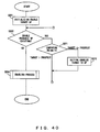
- FIG. 39 is a flowchart of the process of merging service profiles.
- a service profile to be enabled target service profile
- the corresponding area in the service execution data 307 is cleared.
- step S262 it is checked whether or not there is another service profile (probable service profile) specifying the same service as the target service profile. If there is the probable service profile, then one service profile is selected from among the target service profile and the probable service profiles in step S263.
- step S264 the service profile selected in step S263 is enabled.
- FIG. 40 is a flowchart of the embodiment of the selecting process shown in FIG. 39. That is, step S263 shown in FIG. 39 is described as steps S271 and S272. In this embodiment, it is assumed that a priority is set for each service profile.
- step S271 the priority of the target service profile is compared with the priority of the probable service profile. If the priority of the target service profile is higher, then control is returned to step S262. If the priority of the probable service profile is higher, the probable service profile is defined as a target service profile, and control is returned to step S262.
- the service profile having the highest priority is selected. Therefore, in step S264, the service profile having the highest priority is enabled.
- FIGS. 41 and 42 are flowchart of the processes performed when the lifetime of the IPv6 address expires, and corresponds to step S231 shown in FIG. 35.
- FIG. 41 is a flowchart of individually managing source addresses and destination addresses.
- FIG. 42 is a flowchart of managing each service by a combination of a source address and a destination address.
- step S281 in FIG. 41 it is checked whether or not a lifetime has expired for the source address cache (SAC) in the service control data 308. Whether the lifetime has expired in the source address cache or in the destination address cache is set in the lifetime expiration notification generated by the service control unit 302.
- SAC source address cache
- the information about the IPv6 address whose lifetime expiration has been detected is deleted from the policy table and the source address cache in the service control data 308.
- the information about the IPv6 address whose lifetime expiration has been detected is deleted from the source service profile cache and the source host address cache in the service execution data 307.
- the service profile corresponding to the IPv6 address whose lifetime has expired is nullified. For example, in the network shown in FIG. 38, assuming that the lifetime of the IPv6 address assigned to the IPv6 host-A has expired, the service profile of the IPv6 host-B and the IPv6 host-D is nullified.
- the process performed when a lifetime has expired in the destination address cache is basically the same as the process performed when a lifetime has expired in the source address cache. However, when a lifetime expires in the destination address cache, the corresponding information is deleted from the destination service profile cache (DSPC) and the destination host address cache (DHAC) in step S288.
- DSPC destination service profile cache
- DHAC destination host address cache
- the corresponding information is deleted in the address cache (ADC) and the policy table (PT) of the service control data 308 as shown in FIG. 42, the corresponding information is deleted/nullified in the source service profile cache (SSPC) and the source host address cache (SHAC) of the service execution data 307, and the corresponding information is deleted/nullified in the destination service profile cache (DSPC) and the destination host address cache (DHAC) of the service execution data 307.
- ADC address cache
- PT policy table
- the embodiments 1 through 7 below show the sequence of delivering service information corresponding to the host to a node on the communications path when an address of the IPv6 host is assigned or a binding update process is performed (FIGS. 7 and 8).
- the embodiments 8 through 12 show the sequence of the edge node, which performs service control, obtaining the host address information of a correspondent host and/or a service profile (FIG. 9).
- the embodiments 13 through 16 show the sequence of enabling predetermined service information in an edge node.
- the embodiments 17 through 21 show the sequence of nullifying the service information when the lifetime of an IPv6 address expires or when the communications of the IPv6 host terminate.
- DIAMETER protocol is used as an AAA protocol, but the present invention is not limited to this application.
- Embodiment 1 is based on the network configuration shown in FIG. 1.
- AAA server (AAAH) 1 delivers service information to the edge node 21 accommodating the IPv6 host 11.
- the sequence of delivering service information is described below by referring to FIG. 43.
- the sequences of the present and subsequent embodiments 2 through 5 are assumed to start when the IPv6 host 11 or the mobile node 41 receives an ICMP advertisement message from the edge node 21 or 22.
- the edge node 21 accommodating the IPv6 host 11 obtains the service information about the IPv6 host 11. That is, when the IPv6 host 11 turns power on in the communications area of the edge node 21, or the IPv6 host 11 moves into the communications area of the edge node 21 from the communications area of another node, the service information about the IPv6 host 11 is set in the edge node 21.
- the edge node 21 holds the correspondence between the NAI of the IPv6 host 11 and the newly assigned IPv6 address. Therefore, the edge node 21 can provide a corresponding service for a packet transmitted and received by the IPv6 host 11.
- Embodiment is based on the network configuration shown in FIG. 2.
- the AAA server (AAAH) 1 delivers service information to the edge node 22 accommodating the IPv6 host 11.
- the AAA server (AAAH) 1 is set in the home domain of the IPv6 host 11. The delivery sequence of service information is described below by referring to FIG. 44.
- the service information about the Ipv6 host 11 is delivered to the edge node 22 accommodating the IPv6 host 11. Therefore, although the IPv6 host 11 moves to a foreign domain, it can be provided with same service as in the home domain.
- Embodiment 3 is based on the network configuration shown in FIG. 3.
- the AAA server (AAAH) 1 delivers service information to the gateway edge node 31 set in the home domain.
- the AAA server (AAAH) 1 is provided in the home domain of the IPv6 host 11.
- the home domain of the IPv6 host 11 can provide a service specified in the contract for the IPv6 host 11, but a foreign domain to which the edge node 22 belongs cannot provide such a service.
- the sequence of delivering service information is described below by referring to FIG. 45.
- the service information about the IPv6 host 11 is delivered to the gateway edge node 31 provided in the home domain. Therefore, for example, when communications are established between the IPv6 host 11 and the IPv6 host 12 in the network shown in FIG. 3, a service specified in the contract for the IPv6 host 11 is provided for the communications between the gateway edge node 31 and the IPv6 host 12.
- Embodiment 4 is based on the network configuration shown in FIG. 4.
- the AAA server (AAAH) 1 delivers service information to the home agent 42 and the edge node 22 accommodating the mobile node 41.
- the sequence of delivering service information is described below by referring to FIG. 46.
- the service information of the mobile node 41 can be delivered to the home agent 42 and the edge node 22 accommodating the mobile node 11.
- Embodiment 5 is based on the network configuration shown in FIG. 4. In the network, it is assumed that a hierarchical mobile IPv6 is applied.
- the AAA server (AAAH) 1 delivers service information to the home agent 42, the mobility anchor point (MAP) 45 in the domain to which the mobile node 41 belongs, and the edge node 22 accommodating the mobile node 41.
- the sequence of delivering service information is describe below by referring to FIG. 47.
- the service information about the mobile node 41 is delivered to the mobility anchor point (MAP) 45 provided in the foreign domain to which the mobile node belongs.
- MAP mobility anchor point
- Embodiment 6 is based on the network configuration shown in FIG. 4.
- the AAA server (AAAL) 2 delivers service information to the mobility anchor point (MAP) 45 managing the mobile node 41.
- MAP mobility anchor point
- the sequence of delivering the service information is described below by referring to FIG. 48.
- the AAA server (AAAL) 2 is assumed to have obtained the service information about the mobile node 41 in the sequence according to the embodiment 4 or 5.
- the service information about the mobile node 41 can be delivered to the mobility anchor point without accessing the AAA server (AAAH) 1 provided in the home domain, thereby reducing the load on the AAA server (AAAH) 1.
- Embodiment 7 is based on the network configuration shown in FIG. 4.
- this network it is assumed that a hierarchical mobile IPv6 is applied, and the mobile node 41 belongs to a foreign domain.
- the edge node 22 accommodating the mobile node 41 delivers service information to the mobility anchor point (MAP) 45 managing the mobile node 41.
- MAP mobility anchor point
- the sequence of delivering the service information is described below by referring to FIG. 49.
- the edge node 22 is assumed to have obtained the service information about the mobile node 41 in the sequence described above in the embodiment 4 or 5.
- the service information about the mobile node 41 is delivered from the edge node 22 accommodating the mobile node 41 to the mobility anchor point 45 managing the mobile node 41 in the foreign domain without accessing the AAA server.
- Embodiment 8 is based on the network configuration shown in any of FIGS. 1 through 4.
- the IPv6 host 11 is accommodated by the edge node 22, and the IPv6 host 12 is accommodated by the edge node 21.
- the service profile and the host address information about the IPv6 host 11 are set in the edge node 22, and the service profile and the host address information about the IPv6 host 12 are assumed to have been set in the edge node 21.
- the procedure of setting the service profile and host address information about the IPv6 host in the edge node is described above in the embodiments 1, 2, 4, and 5.
- the IPv6 host can be a mobile IPv6 terminal.
- the edge node 22 accommodating a source host (IPv6 host 11) obtains host address information and/or service profile of the destination host from the edge node 21 accommodating the destination host (IPv6 host 12).
- IPv6 host 11 IPv6 host 11
- IPv6 host 12 IPv6 host 12
- the sequence of transferring the host address information and/or service profile of the IPv6 host between edge nodes is described below by referring to FIG. 50.
- the edge node accommodating the source host can obtain the service profile and/or host address information about the destination host from the edge node accommodating the destination host.
- Embodiment 9 is based on the network configuration shown in any of FIGS. 1 through 4.
- the IPv6 hosts 11 and 12, and the edge nodes 21 and 22 are assumed to be the same as those according to the embodiment 8.
- the host address information about the source host IPv6 host 11
- the edge node 22 accommodating the source host to the edge node 21 accommodating the destination host (IPv6 host 12).
- the sequence of transferring the host address information about the IPv6 host between edge nodes is described below by referring to FIG. 51.
- the edge node accommodating the destination host can obtain the host address information about the source host from the edge node accommodating the source host.
- only the host address information about the source host is transmitted, but both of the service profile and the host address information about the source host can be transferred.
- Embodiment 10 is based on the network configuration shown in any of FIGS. 1 through 4.
- the IPv6 host 11 and 12, and the edge nodes 21 and 22 are the same those according to the embodiment 8 or 9.
- the service profiles and the host address information are exchanged between the edge node 22 accommodating the source host (IPv6 host 11) and the edge node 21 accommodating the destination host (IPv6 host 12).
- the sequence of transferring the service profiles and the host address information about the IPv6 hosts between the edge nodes is described below by referring to FIG. 52.
- the sequence according to the embodiment 10 can be realized by combining the sequences according to the embodiments 8 and 9.
- each edge node can individually select the optimum service information from the service information about the IPv6 hosts being in communications.
- Embodiment 11 is based on the network configuration shown in FIG. 4.
- the mobile node 41 is accommodated in the edge node 22, and the correspondent node (CN) 42 is accommodated in the edge node 21.
- a service profile and host address information about the mobile node 41 is stored in home agent 43. The procedure of setting service profile and the host address information about the mobile node 41 in the home agent is described according to the embodiments 4 and 5.
- the service profile and the host address information about the destination host are transferred from the home agent 43 managing the destination host (mobile node 41) to the edge node 21 accommodating the source host (correspondent node 42) when the packet transmission from the correspondent node 42 to the mobile node 41 is started in the above mentioned environment.
- the sequence of transferring the service profile and the host address information about the mobile node is described below by referring to FIG. 53.
- the edge node accommodating the source host can obtain the service profile and the host address information about the destination host from the home agent of the destination host. That is, the service profile and the host address information can be transferred through a shorter path depending on the relative locations between the source host and the destination host.
- Embodiment 12 is based on the network configuration shown in FIG. 4.
- a hierarchical mobile IPv6 is applied to the network, and the mobility anchor point (MAP) 45 is provided in the foreign domain to which the mobile node 41 moves.
- the mobile node 41, the correspondent node 42, the edge nodes 21 and 22 are the same as those according to the embodiment 11.
- the service profile and the host address information about the destination host are transferred from the mobility anchor point 45 managing the destination host (mobile node 41) to the edge node 21 accommodating the source host (correspondent node 42) when the transmission of a packet from the correspondent node 42 to the mobile node 41 is started in the above mentioned environment.
- the sequence of transferring the service profile and the host address information about the mobile node is described below by referring to FIG. 54.
- the service profile and the host address information can be transferred through a shorter path depending on the relative positions between the source host and the destination host.
- the edge node accommodating the source terminal checks the address when data transfer is started between terminal devices. Depending on the checking result, a service profile is enabled, and the service profile and/or the host address information are transferred between edge nodes.
- the present invention is not limited to this application. That is, for example, when data transfer is started between terminal devices, the address is checked in the edge node accommodating the destination terminal, and similar processes are performed depending on the check result.
- a service profile corresponding to the communication node accommodating the IPv6 host is delivered when an address is assigned to the IPv6 host as described above. Then, a communications service is provided according to the delivered service profile.
- the delivered service profile is enabled when it is actually used. That is, the delivered service profile is enabled when the communications is started by an IPv6 host. Practically, upon receipt of a packet from the IPv6 host, an edge node first recognizes the service to be provided based on the source address and the destination address of the packet. Then, it checks whether or not the service has ever been provided. If the service has been provided, then the service is provided according to the service profile used before. If the service has never been provided before, a policy table is generated to provide the service by enabling the service profile.
- a service profile corresponding to the service is to be prepared and enabled.
- Each service is basically specified by the source address and the destination address of a packet. Therefore, whether or not a service has ever been provided can be recognized by checking whether or not a packet having the source address and the destination address of the service has ever been received.
- the edge node has the function of storing the source address and the destination address of a received packet in the address cache, the function of checking whether or not the source address and the destination address of a packet have been stored in the address cache when the packet is received from the IPv6 host, and the function of enabling the corresponding service profile if the addresses have not been stored.
- the embodiment 13 shows the sequence of enabling the service profile corresponding a packet when the source address of the received packet has not been stored in the address cache in the edge node with the above mentioned configuration.
- the address cache is configured such that a source address and a destination address are individually managed as shown in FIGS. 25A and 25B.
- the case in which the source address of a received packet is not stored in the address cache is hereinafter referred to as a "source cache miss".
- the enabling sequence according to the embodiment 13 is described below by referring to FIG. 55.
- Embodiment 14 shows the sequence of enabling a service profile corresponding to a packet when the destination address of the received packet is not stored in the address cache.
- the address cache is assumed to be configured such that a source address and a destination address are individually managed.
- the case in which the destination address of a received packet is not stored in the address cache is referred to as a "destination cache miss".
- the enabling sequence in the embodiment 14 is described below by referring to FIG. 56.
- Embodiment 15 shows the sequence of enabling a corresponding service profile when both of the source address and the destination address of the received packet are not stored in the address cache.
- the address cache is assumed to be configured such that a source address and a destination address are individually managed.
- FIG. 57 shows the sequence according to the embodiment 15.
- the sequence according to the embodiment 15 is basically realized by combining the processes according to the embodiments 13 and 14. Therefore, the detailed explanation of the embodiment 15 is omitted here. However, in the embodiment 15, the information indicating that both source hit miss and destination hit miss have occurred is stored in the hit miss notification transmitted from the service control unit 302 to the service data management unit 305.
- an address cache has the configuration of managing the combination of a source address and a destination address as shown in FIG. 26A. If the combination of the source address and the destination address of a received packet is not stored in the address cache, then the service profile corresponding to the packet is enabled. The enabling sequence of the embodiment 16 is described below by referring to FIG. 58.
- the address cache (ADC) of the service control data 308 is checked. However, in this embodiment 16, it is checked whether or not the combination of the source address and the destination address of a received packet is stored in the address cache. In this example, it is assumed that no such combination is stored.
- this edge node transmits an NAI-SPC request message to the edge node accommodating the destination host, obtains the corresponding host address information and service profile by receiving a NAI-SPC reply message, and sets them in the service execution data 307 and the service control data 308.
- a predetermined lifetime is set for the IPv6 address assigned to each IPv6 host. If the lifetime of an IPv6 address expires, the service information corresponding to the address is nullified. That is, if the service information about an IPv6 host is set in an edge node, and if the lifetime of the IPv6 address expires, then the corresponding service information is deleted or nullified.
- the service information corresponding to the address is nullified.
- the address cache is assumed to be configured such that a source address and a destination address are individually managed. The nullifying sequence according to the embodiment 17 is described below by referring to FIG. 59.
- the service information corresponding to the address is nullified.
- the address cache is assumed to be configured such that a source address and a destination address are individually managed.
- the nullifying sequence according to the embodiment 18 is described below by referring to FIG. 60.
- Embodiment 19 is based on the combination of a source address and a destination address to be managed in the address cache. When the lifetime set for a combination of a source address and a destination address has expired, the service information corresponding to the combination is nullified.
- the nullifying sequence according to the embodiment 19 is described below by referring to FIG. 61.
- the corresponding service information is nullified when the lifetime set for an IPv6 address expires.
- the service information set for the edge node is nullified at a request from a terminal (an IPv6 host, a mobile node). Practically, when a session release request is transmitted from an IPv6 host, corresponding service information in the edge node is nullified/deleted. The sequence according to the embodiment 20 is described below by referring to FIG. 62.
- the service information at an edge node accommodating a terminal is deleted/nullified at a request from the terminal.
- the service information is delivered from the edge node to another communication node, the service information is similarly deleted/nullified also in that communication node.
- the sequence according to the embodiment 21 is described by referring to FIG. 63.
- the IPv6 host 11 is assumed to have communicated with the IPv6 host 12. Additionally, the IPv6 host 11 is accommodated in the edge node 21, and the IPv6 host 12 is accommodated in the edge node 22. It is assumed that service information about the IPv6 host 11 has been transferred from the edge node 21 to the edge node 22, when the communications between them were started.
- the edge node 22 receives the NAI-SPC request message by the edge node 21 transmitting the NAI-SPC request message to the IPv6 host 12 which has been the correspondent of the edge node 21.
- the edge node can directly realize the destination of the NAI-SPC request message transmitted in (6) above if the destination address of the service information about the IPv6 host is stored in the "destination IPv6 address" of the original host address cache shown in FIG. 13B when the service information of the IPv6 host is delivered to another correspondent node.
- the address request procedure is linked to the authentication protocol in the network in which the service information is delivered from the server device to the router device through the authentication protocol, the service information for all terminal devices to which an address is assigned can be delivered, and each terminal device can be provided with a corresponding service.
- service information relating to the communications between terminals can be transmitted and received between a router device accommodating a source terminal and a router device accommodating a destination terminal, an appropriate service can be provided without accessing a server device.
Landscapes
- Engineering & Computer Science (AREA)
- Computer Hardware Design (AREA)
- Computer Security & Cryptography (AREA)
- Computing Systems (AREA)
- General Engineering & Computer Science (AREA)
- Computer Networks & Wireless Communication (AREA)
- Signal Processing (AREA)
- Data Exchanges In Wide-Area Networks (AREA)
- Computer And Data Communications (AREA)
Applications Claiming Priority (3)
| Application Number | Priority Date | Filing Date | Title |
|---|---|---|---|
| JP2001189497A JP2003008622A (ja) | 2001-06-22 | 2001-06-22 | サービス制御ネットワーク、及びそのサービス制御ネットワークにおいて使用されるルータ装置 |
| JP2001189497 | 2001-06-22 | ||
| PCT/JP2001/006102 WO2003001752A1 (en) | 2001-06-22 | 2001-07-13 | Service control network |
Publications (1)
| Publication Number | Publication Date |
|---|---|
| EP1416680A1 true EP1416680A1 (de) | 2004-05-06 |
Family
ID=19028404
Family Applications (1)
| Application Number | Title | Priority Date | Filing Date |
|---|---|---|---|
| EP20010949977 Withdrawn EP1416680A1 (de) | 2001-06-22 | 2001-07-13 | Dienststeuernetzwerk |
Country Status (4)
| Country | Link |
|---|---|
| US (1) | US20020199104A1 (de) |
| EP (1) | EP1416680A1 (de) |
| JP (1) | JP2003008622A (de) |
| WO (1) | WO2003001752A1 (de) |
Families Citing this family (30)
| Publication number | Priority date | Publication date | Assignee | Title |
|---|---|---|---|---|
| US7502929B1 (en) * | 2001-10-16 | 2009-03-10 | Cisco Technology, Inc. | Method and apparatus for assigning network addresses based on connection authentication |
| AU2003217301A1 (en) * | 2002-02-04 | 2003-09-02 | Flarion Technologies, Inc. | A method for extending mobile ip and aaa to enable integrated support for local access and roaming access connectivity |
| US8649352B2 (en) | 2002-02-04 | 2014-02-11 | Qualcomm Incorporated | Packet forwarding methods for use in handoffs |
| US7143435B1 (en) * | 2002-07-31 | 2006-11-28 | Cisco Technology, Inc. | Method and apparatus for registering auto-configured network addresses based on connection authentication |
| CN100539586C (zh) * | 2003-06-18 | 2009-09-09 | 艾利森电话股份有限公司 | 支持分级移动ip业务的方法、系统和设备 |
| US20060185013A1 (en) * | 2003-06-18 | 2006-08-17 | Telefonaktiebolaget Lm Ericsson (Publ) | Method, system and apparatus to support hierarchical mobile ip services |
| JP4377409B2 (ja) * | 2003-06-18 | 2009-12-02 | テレフオンアクチーボラゲット エル エム エリクソン(パブル) | モバイルIP(モバイルIP:MobileIP)バージョン6サービスをサポートするための方法、システム及び装置 |
| JP3965382B2 (ja) * | 2003-11-28 | 2007-08-29 | 松下電器産業株式会社 | 通信システム及び通信方法 |
| GB0329499D0 (en) * | 2003-12-19 | 2004-01-28 | Nokia Corp | Communication network |
| KR100803272B1 (ko) | 2004-01-29 | 2008-02-13 | 삼성전자주식회사 | 아이피 브이 식스 네트워크에서 인증을 처리하는 방법 및그 장치 |
| WO2005104500A1 (en) * | 2004-04-23 | 2005-11-03 | Telefonaktiebolaget Lm Ericsson (Publ) | Aaa support for dhcp |
| US20090232150A1 (en) * | 2004-08-27 | 2009-09-17 | Nortel Networks Limited | Service edge platform architecture for a multi-service access network |
| CN100344094C (zh) * | 2004-09-01 | 2007-10-17 | 华为技术有限公司 | IPv6网络中对多地址用户进行授权计费的实现方法 |
| US7660253B2 (en) * | 2005-02-14 | 2010-02-09 | Telefonaktiebolaget L M Ericsson (Publ) | Method and nodes for aggregating data traffic through unicast messages over an access domain using service bindings |
| ATE421206T1 (de) * | 2005-02-14 | 2009-01-15 | Ericsson Telefon Ab L M | Verfahren und knoten zur durchführung einer überbrückung von datenverkehr über eine zugangsdomäne |
| US7881198B2 (en) * | 2005-04-25 | 2011-02-01 | Telefonaktiebolaget L M Ericsson (Publ) | Method for managing service bindings over an access domain and nodes therefor |
| US20080120714A1 (en) * | 2006-11-20 | 2008-05-22 | Telefonaktiebolaget Lm Ericsson (Publ) | Method for authenticating nomadic user domains and nodes therefor |
| US8281383B2 (en) * | 2006-12-11 | 2012-10-02 | Cisco Technology, Inc. | Secured IPv6 traffic preemption |
| US8656449B1 (en) * | 2007-07-30 | 2014-02-18 | Sprint Communications Company L.P. | Applying policy attributes to events |
| JP4802238B2 (ja) * | 2008-12-08 | 2011-10-26 | パナソニック株式会社 | ローカルネットワーク相互接続における移動端末に対してネットワークに基づくトンネルを設定する方法 |
| US20110274029A1 (en) * | 2010-05-10 | 2011-11-10 | Comcast Cable Communications, Llc | Wireless Range Extender |
| US20110287748A1 (en) * | 2010-05-18 | 2011-11-24 | Albert Angel | Consent, Signature and Recording Retention in a Certified Communications System |
| US8925040B2 (en) * | 2010-06-17 | 2014-12-30 | Cellco Partnership | Preventing multiple backend calls at browser launch during mobile broadband provisioning |
| JP5548928B2 (ja) * | 2011-05-30 | 2014-07-16 | 日本電信電話株式会社 | ネットワーク情報管理方法、ネットワーク情報管理プログラムおよび通信装置 |
| US9100214B1 (en) * | 2011-06-28 | 2015-08-04 | Juniper Networks, Inc. | Performing customer bandwidth profiling in computer networks |
| US9894599B2 (en) * | 2012-06-13 | 2018-02-13 | Qualcomm, Incorporated | Method and apparatus for WLAN initial link setup |
| US8817707B2 (en) * | 2012-07-20 | 2014-08-26 | Intel Corporation | Mechanisms for roaming between 3GPP operators and WLAN service providers |
| US9734229B1 (en) * | 2013-09-10 | 2017-08-15 | Symantec Corporation | Systems and methods for mining data in a data warehouse |
| US9830349B2 (en) * | 2014-10-31 | 2017-11-28 | Vmware, Inc. | Maintaining storage profile consistency in a cluster having local and shared storage |
| CN115696333A (zh) * | 2021-07-30 | 2023-02-03 | 华为技术有限公司 | 一种无线通信方法和装置 |
Family Cites Families (19)
| Publication number | Priority date | Publication date | Assignee | Title |
|---|---|---|---|---|
| US5828846A (en) * | 1995-11-22 | 1998-10-27 | Raptor Systems, Inc. | Controlling passage of packets or messages via a virtual connection or flow |
| US6400701B2 (en) * | 1998-03-31 | 2002-06-04 | Nortel Networks Limited | Asymmetric internet access over fixed wireless access |
| WO2000008812A1 (en) * | 1998-08-04 | 2000-02-17 | At & T Corp. | A method for allocating network resources |
| US6973057B1 (en) * | 1999-01-29 | 2005-12-06 | Telefonaktiebolaget L M Ericsson (Publ) | Public mobile data communications network |
| US6463474B1 (en) * | 1999-07-02 | 2002-10-08 | Cisco Technology, Inc. | Local authentication of a client at a network device |
| DE19933222A1 (de) * | 1999-07-26 | 2001-02-08 | Siemens Ag | Verfahren und Kommunikationssystem zur Behandlung eines Paketdienstes |
| US6769000B1 (en) * | 1999-09-08 | 2004-07-27 | Nortel Networks Limited | Unified directory services architecture for an IP mobility architecture framework |
| JP4162347B2 (ja) * | 2000-01-31 | 2008-10-08 | 富士通株式会社 | ネットワークシステム |
| JP2001237876A (ja) * | 2000-02-21 | 2001-08-31 | Nec Corp | Ip仮想プライベート網の構築方法及びip仮想プライベート網 |
| US6992994B2 (en) * | 2000-04-17 | 2006-01-31 | Telcordia Technologies, Inc. | Methods and systems for a generalized mobility solution using a dynamic tunneling agent |
| JP2002033764A (ja) * | 2000-07-14 | 2002-01-31 | Fujitsu Ltd | 通信サービス提供システム、並びに通信サービス提供システムにおいて使用される移動端末装置、アドレスサーバ装置、およびルータ装置 |
| US6910074B1 (en) * | 2000-07-24 | 2005-06-21 | Nortel Networks Limited | System and method for service session management in an IP centric distributed network |
| US6925075B2 (en) * | 2000-07-31 | 2005-08-02 | Telefonaktiebolaget Lm Ericsson | Method and system for inter-operability between mobile IP and RSVP during route optimization |
| US6954790B2 (en) * | 2000-12-05 | 2005-10-11 | Interactive People Unplugged Ab | Network-based mobile workgroup system |
| US6879690B2 (en) * | 2001-02-21 | 2005-04-12 | Nokia Corporation | Method and system for delegation of security procedures to a visited domain |
| US20020118674A1 (en) * | 2001-02-23 | 2002-08-29 | Faccin Stefano M. | Key distribution mechanism for IP environment |
| US20020136226A1 (en) * | 2001-03-26 | 2002-09-26 | Bluesocket, Inc. | Methods and systems for enabling seamless roaming of mobile devices among wireless networks |
| US6999435B2 (en) * | 2001-03-29 | 2006-02-14 | Telefonaktiebolaget Lm Ericsson (Publ) | Method, system and node for providing enhanced mobility in simple IP telecommunication networks when performing L2TP tunneling |
| US7110375B2 (en) * | 2001-06-28 | 2006-09-19 | Nortel Networks Limited | Virtual private network identification extension |
-
2001
- 2001-06-22 JP JP2001189497A patent/JP2003008622A/ja not_active Withdrawn
- 2001-07-13 EP EP20010949977 patent/EP1416680A1/de not_active Withdrawn
- 2001-07-13 WO PCT/JP2001/006102 patent/WO2003001752A1/ja not_active Ceased
-
2002
- 2002-04-10 US US10/122,111 patent/US20020199104A1/en not_active Abandoned
Non-Patent Citations (1)
| Title |
|---|
| See references of WO03001752A1 * |
Also Published As
| Publication number | Publication date |
|---|---|
| JP2003008622A (ja) | 2003-01-10 |
| US20020199104A1 (en) | 2002-12-26 |
| WO2003001752A1 (en) | 2003-01-03 |
Similar Documents
| Publication | Publication Date | Title |
|---|---|---|
| EP1416680A1 (de) | Dienststeuernetzwerk | |
| JP4201466B2 (ja) | モバイルipネットワークにおけるvpnシステム及びvpnの設定方法 | |
| US7328014B2 (en) | Communication system, gateway equipment, communication method and authentication method | |
| US6442616B1 (en) | Method and apparatus for communication control of mobil computers in communication network systems using private IP addresses | |
| JP4034729B2 (ja) | モバイルインターネット通信装置及び方法 | |
| JP4861426B2 (ja) | モビリティキーを提供する方法とサーバ | |
| US7873825B2 (en) | Identification method and apparatus for establishing host identity protocol (HIP) connections between legacy and HIP nodes | |
| US20040037260A1 (en) | Virtual private network system | |
| CA2321396C (en) | Mobile communications service system, mobile communications service method, authentication apparatus, and home agent apparatus | |
| US20020006133A1 (en) | Communications service providing system, and mobile terminal device, address server device, and router device for use therewith | |
| US20040095913A1 (en) | Routing optimization proxy in IP networks | |
| US20010012777A1 (en) | Mobile communications system and method thereof | |
| EP1735990B1 (de) | Authentifizierung und authorisierung für mobile ipv6 | |
| JP2001217866A (ja) | ネットワークシステム | |
| JP2001237878A (ja) | 移動通信サービス提供システム、および移動通信サービス提供方法 | |
| Huston | Architectural approaches to multi-homing for IPv6 | |
| KR100964350B1 (ko) | IPv6 환경에서의 SEND와 IPSec 협업 기법 및시스템 | |
| JP4305087B2 (ja) | 通信ネットワークシステム及びそのセキュリティ自動設定方法 | |
| CN101106806A (zh) | 无线网络获得移动终端移动ip类型的方法、系统及移动终端 | |
| US7756061B2 (en) | Mobile router device and home agent device | |
| KR100419578B1 (ko) | 다이아미터 기반 이동 인터넷 프로토콜 망에서의 세션제어 방법 | |
| JP3812455B2 (ja) | ゲートウェイ装置およびその位置登録方法、認証方法、位置管理方法、ならびにそのプログラムと記録媒体 | |
| CN101141386B (zh) | 路由优化管理方法及其装置 | |
| JP2005198153A (ja) | ホームエージェント装置 | |
| KR101266931B1 (ko) | Aaa 프로토콜을 기반으로 하는 통합 보안인증 체계의 구축을 통한 보안인증 방법 |
Legal Events
| Date | Code | Title | Description |
|---|---|---|---|
| PUAI | Public reference made under article 153(3) epc to a published international application that has entered the european phase |
Free format text: ORIGINAL CODE: 0009012 |
|
| 17P | Request for examination filed |
Effective date: 20020516 |
|
| AK | Designated contracting states |
Kind code of ref document: A1 Designated state(s): DE FR GB SE |
|
| RIN1 | Information on inventor provided before grant (corrected) |
Inventor name: IGARASHI, YOICHIRO,C/O FUJITSU LIMITED Inventor name: IWAMOTO, K.C/O FUJITSU NISHI-NIHON COM. SYST. LTD Inventor name: YAMAMURA, S.FUJITSU NISHI-NIHON COM. SYST. LTD Inventor name: MURATA, K., Inventor name: KAKEMIZU, MITSUAKI,C/O FUJITSU LIMITED Inventor name: WAKAMOTO, MASAAKI,C/O FUJITSU LIMITED |
|
| STAA | Information on the status of an ep patent application or granted ep patent |
Free format text: STATUS: THE APPLICATION HAS BEEN WITHDRAWN |
|
| 18W | Application withdrawn |
Effective date: 20080311 |